INSTRUCTION MANUAL - Instruction... · • Avoid all contact with live electrical parts of the...
16
INSTRUCTION MANUAL QLD Schools / TAFE - MIG/MMA/TIG Compact 250K Multi-Function Inverter Welder (240V) 10-250A K8771 Page 1 Instruction Manual for MIG/MMA/TIG Compact 250K (K8771) 11/27/2015
Transcript of INSTRUCTION MANUAL - Instruction... · • Avoid all contact with live electrical parts of the...
INSTRUCTION MANUALQLD Schools / TAFE - MIG/MMA/TIG
Compact 250KMulti-Function Inverter Welder (240V)
10-250A
K8771
Page 1 Instruction Manual for MIG/MMA/TIG Compact 250K (K8771) 11/27/2015
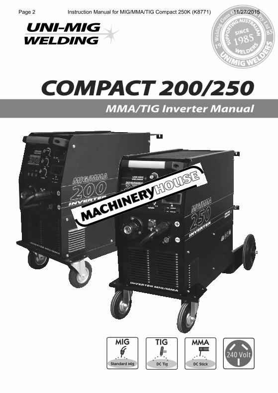
COMPACT 200/250MMA/TIG Inverter Manual
UNI FLAME AUTOLIFT
240 Volt
Page 2 Instruction Manual for MIG/MMA/TIG Compact 250K (K8771) 11/27/2015
Machine Model
Description Part Number MIG/MMA/TIG Inverter KUMJR200K / 250K
CONTENTS PAGE No:
Safety 3
General Description 4
Curcuit Diagram 5
Main Parameter 6
Panel Instructions 7
Operation 9
Maintenance 15
TroubleShooting 15
UN
IFLA
ME
AUTO
LIFT
UNIMIG pursue a policy of continuous research and development, and therefore reserve the right to change the specifications, or design, without prior notice. * 2 year warranty power source.
This welding machine for industrial and professional use is in the conformity with IEC 60974 International Safety Standard.
Hereby we state that we provide two years of guarantee for this welding machine since the date of purchase.
Please read and understand this instruction manual carefully before the installation and operation of this machine.
The contents of this manual may be revised without prior notice.
This instruction manual is issued on August 2008.
YEARS Warranty*2Page 3 Instruction Manual for MIG/MMA/TIG Compact 250K (K8771) 11/27/2015
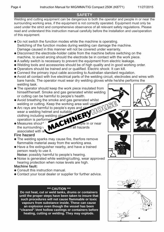
• Do not switch the function modes while the machine is operating. Switching of the function modes during welding can damage the machine. Damage caused in this manner will not be covered under warranty.• Disconnect the electrode-holder cable from the machine before switching on the machine, to avoid arcing should the electrode be in contact with the work piece.• A safety switch is necessary to prevent the equipment from electric leakage.• Welding tools and accessories should be of high quality and in good working order. • Operators should be trained and or qualified. Electric shock: It can kill. • Connect the primary input cable according to Australian standard regulation.• Avoid all contact with live electrical parts of the welding circuit, electrodes and wires with bare hands. The operator must wear dry welding gloves while he/she performs the welding task.• The operator should keep the work piece insulated from himself/herself. Smoke and gas generated whilst welding or cutting can be harmful to people’s health.• Avoid breathing the smoke and gas generated whilst welding or cutting. Keep the working area well ventilated. • Arc rays are harmful to people’s eyes and skin. Always wear a welding helmet and suitable protective clothing including welding gloves whilst the welding operation is performed.• Measures should be taken to protect people in or near the surrounding working area, from all hazards associated with welding.Fire hazard• The welding sparks may cause fire, therfore remove flammable material away from the working area.• Have a fire extinguisher nearby, and have a trained person ready to use it. Noise: possibly harmful to people’s hearing.• Noise is generated while welding/cutting, wear approved hearing protection when noise levels are high. Machine fault:• Consult this instruction manual.• Contact your local dealer or supplier for further advice.
SAFETYWelding and cutting equipment can be dangerous to both the operator and people in or near the surrounding working area, if the equipment is not correctly operated. Equipment must only be used under the strict and comprehensive observance of all relevant safety regulations. Please read and understand this instruction manual carefully before the installation and use/operation of this equipment.
*** CAUTION ***Do not heat, cut or weld tanks, drums or containers until the proper steps have been taken to insure that such procedures will not cause flammable or toxic vapours from substance inside. These can cause
an explosion even though the vessel has been “cleaned”.Vent hollow castings or containers before
heating, cutting or welding. They may explode.
Page 4 Instruction Manual for MIG/MMA/TIG Compact 250K (K8771) 11/27/2015
UN
IFLA
ME
AUTO
LIFT
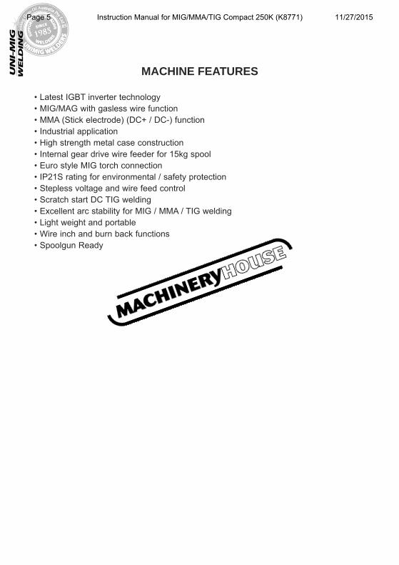
• Latest IGBT inverter technology• MIG/MAG with gasless wire function• MMA (Stick electrode) (DC+ / DC-) function• Industrial application• High strength metal case construction• Internal gear drive wire feeder for 15kg spool• Euro style MIG torch connection• IP21S rating for environmental / safety protection• Stepless voltage and wire feed control• Scratch start DC TIG welding• Excellent arc stability for MIG / MMA / TIG welding• Light weight and portable• Wire inch and burn back functions• Spoolgun Ready
MACHINE FEATURES
Page 5 Instruction Manual for MIG/MMA/TIG Compact 250K (K8771) 11/27/2015
UN
IFLA
ME
AUTO
LIFT
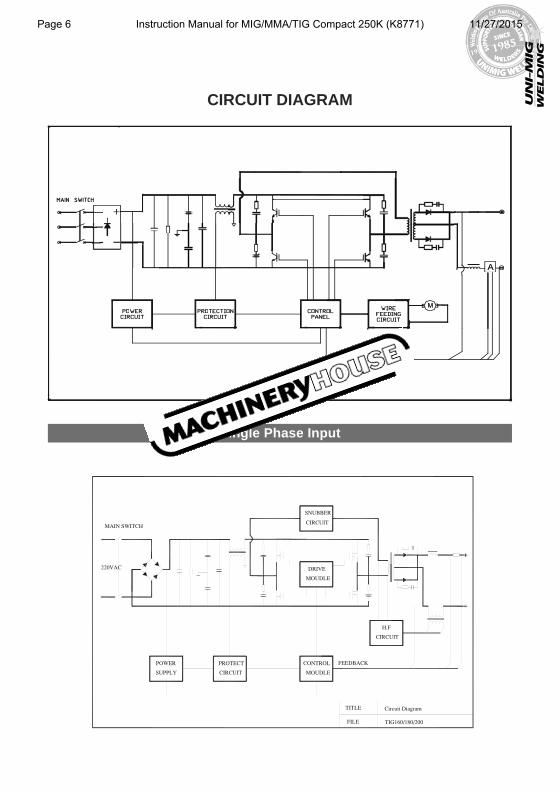
CIRCUIT DIAGRAM
Single Phase Input
Page 6 Instruction Manual for MIG/MMA/TIG Compact 250K (K8771) 11/27/2015
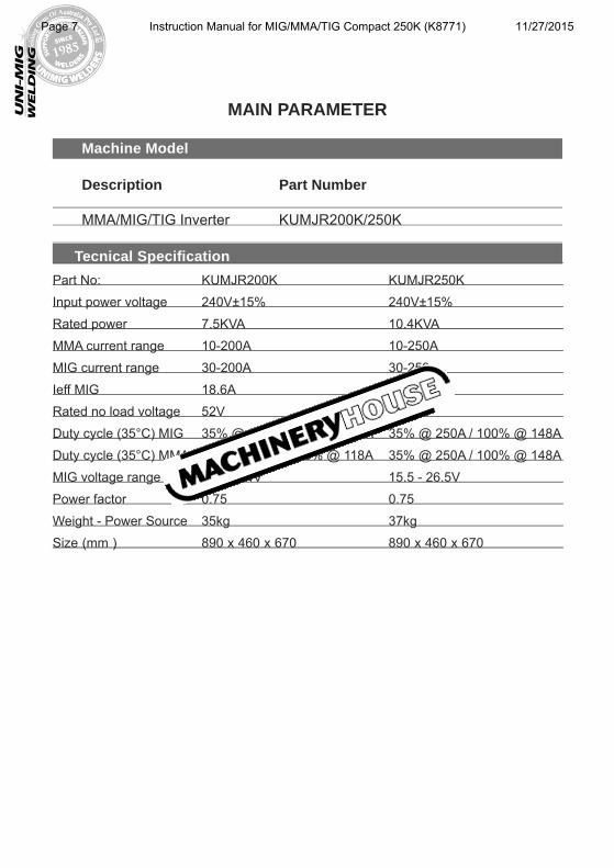
Machine Model
Description Part Number
MMA/MIG/TIG Inverter KUMJR200K/250K
MAIN PARAMETER
UN
IFLA
ME
AUTO
LIFT
Tecnical SpecificationPart No: KUMJR200K KUMJR250K
Input power voltage 240V±15% 240V±15%
Rated power 7.5KVA 10.4KVA
MMA current range 10-200A 10-250A
MIG current range 30-200A 30-250A
Ieff MIG 18.6A 25.4A
Rated no load voltage 52V 52V
Duty cycle (35°C) MIG 35% @ 200A / 100% @ 118A 35% @ 250A / 100% @ 148A
Duty cycle (35°C) MMA 35% @ 200A / 100% @ 118A 35% @ 250A / 100% @ 148A
MIG voltage range 15.5 - 24V 15.5 - 26.5V
Power factor 0.75 0.75
Weight - Power Source 35kg 37kg
Size (mm ) 890 x 460 x 670 890 x 460 x 670
Page 7 Instruction Manual for MIG/MMA/TIG Compact 250K (K8771) 11/27/2015
UN
IFLA
ME
AUTO
LIFT
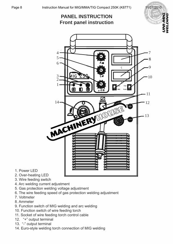
PANEL INSTRUCTIONFront panel instruction
1. Power LED2. Over-heating LED3. Wire feeding switch4. Arc welding current adjustment5. Gas protection welding voltage adjustment 6. The wire feeding speed of gas protection welding adjustment7. Voltmeter8. Ammeter9. Function switch of MIG welding and arc welding 10. Function switch of wire feeding torch11. Socket of wire feeding torch control cable12. “+” output terminal13. “-” output terminal14. Euro-style welding torch connection of MIG welding
456
321
14
7
8
9
10
11
12
13
Page 8 Instruction Manual for MIG/MMA/TIG Compact 250K (K8771) 11/27/2015
UN
IFLA
ME
AUTO
LIFT
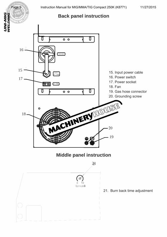
Back panel instruction
Middle panel instruction
15. Input power cable16. Power switch17. Power socket18. Fan 19. Gas hose connector20. Grounding screw
21. Burn back time adjustment
16
15
17
18
20
19
21
Page 9 Instruction Manual for MIG/MMA/TIG Compact 250K (K8771) 11/27/2015
UN
IFLA
ME
AUTO
LIFT
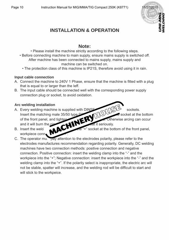
INSTALLATION & OPERATION
Note: • Please install the machine strictly according to the following steps.
• Before connecting machine to main supply, ensure mains supply is switched off.After machine has been connected to mains supply, mains supply and
machine can be switched on.• The protection class of this machine is IP21S, therefore avoid using it in rain.
Input cable connectionA. Connect the machine to 240V 1 Phase, ensure that the machine is fitted with a plug that is equal to or larger than the Ieff.B. The input cable should be connected well with the corresponding power supply connection plug or socket, to avoid oxidation.
Arc welding installationA. Every welding machine is supplied with DINSE type 35/50 female sockets. Insert the matching male 35/50 type DINSE connector into the socket at the bottom of the front panel, and tighten it, ensure contact good. Otherwise arcing can occur and it will burn the pin and socket. Please treat it seriously.B. Insert the welding clamp cable into the “+” socket at the bottom of the front panel, workpiece connect with the“-”. C. The operator must pay attention to the electrodes polarity, please refer to the electrodes manufactures recommendation regarding polarity. Generally, DC welding machines have two connection methods: positive connection and negative connection. Positive connection: insert the welding clamp into the “-” and the workpiece into the “+”; Negative connection: insert the workpiece into the “-” and the welding clamp into the “+”. If the polarity select is inappropriate, the electric arc will not be stable, spatter will increase, and the welding rod will be difficult to start and will stick to the workpeice.
Page 10 Instruction Manual for MIG/MMA/TIG Compact 250K (K8771) 11/27/2015
UN
IFLA
ME
AUTO
LIFT
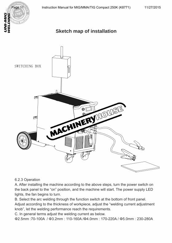
Sketch map of installation
6.2.3 OperationA. After installing the machine according to the above steps, turn the power switch on the back panel to the “on” position, and the machine will start. The power supply LED lights, the fan begins to turn. B. Select the arc welding through the function switch at the bottom of front panel. Adjust according to the thickness of workpiece, adjust the “welding current adjustment knob”, let the welding performance reach the requirements. C. In general terms adjust the welding current as below. Φ2.5mm :70-100A / Φ3.2mm : 110-160A /Φ4.0mm : 170-220A / Φ5.0mm : 230-280A
Page 11 Instruction Manual for MIG/MMA/TIG Compact 250K (K8771) 11/27/2015
UN
IFLA
ME
AUTO
LIFT
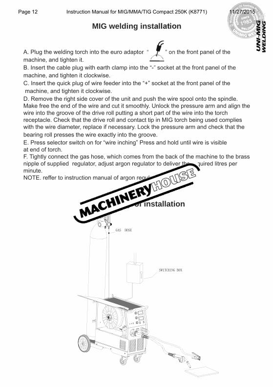
MIG welding installation
A. Plug the welding torch into the euro adaptor “ ” on the front panel of the machine, and tighten it. B. Insert the cable plug with earth clamp into the “-” socket at the front panel of the machine, and tighten it clockwise.C. Insert the quick plug of wire feeder into the “+” socket at the front panel of the machine, and tighten it clockwise. D. Remove the right side cover of the unit and push the wire spool onto the spindle. Make free the end of the wire and cut it smoothly. Unlock the pressure arm and align the wire into the groove of the drive roll putting a short part of the wire into the torch receptacle. Check that the drive roll and contact tip in MIG torch being used complies with the wire diameter, replace if necessary. Lock the pressure arm and check that the bearing roll presses the wire exactly into the groove. E. Press selector switch on for “wire inching” Press and hold until wire is visible at end of torch.F. Tightly connect the gas hose, which comes from the back of the machine to the brass nipple of supplied regulator, adjust argon regulator to deliver the required litres per minute. NOTE. reffer to instruction manual of argon regulator for proper use.
Sketch map of installation
Page 12 Instruction Manual for MIG/MMA/TIG Compact 250K (K8771) 11/27/2015
UN
IFLA
ME
AUTO
LIFT
Installation of gas shielded arc welding
(1) Turn the power source on and select the MIG function through the STICK/MIG selector. (2) Plug the welding torch into the output socket “14” on the front panel, and tighten it.(3) Insert the welding cable with earth clamp fitted into the positive socket “12” on the Panel Structure Diagram, and tighten it clockwise.(4) Insert the fast plug into the negative socket “13” on the front of the machine, and tighten it clockwise. (5) Adjust the welding voltage adjustment knob and wire feeding speed adjustment knob according to practical needs to get the desired welding voltage and welding current. (See Panel Structure Diagram Number 5&6)(6) Press the welding torch switch, and welding can be carried out.(7) Adjust the burnback time potentiometer on the rear panel to get the desired length of welding wire stretching into the contact tip after welding.
(1) Turn the power source on and select the MIG function through the STICK/MIG selector. (2) Plug the welding torch into the output socket “14” on the front panel, and tighten it.(3) Insert the welding cable with earth clamp fitted into the negative socket “13” on the Panel Structure Diagram, and tighten it clockwise.(4) Insert the fast plug into the positive socket “12” on the front of the machine, and tighten it clockwise. (5) Adjust the welding voltage adjustment knob and wire feeding speed adjustment knob according to practical needs to get the desired welding voltage and welding current. (See Panel Structure Diagram Number 5&6)(6) Press the welding torch switch, and welding can be carried out.(7) Adjust the burnback time potentiometer on the rear panel to get the desired length of welding wire stretching into the contact tip after welding.
Installation of self shielded arc welding (No Gas)
Page 13 Instruction Manual for MIG/MMA/TIG Compact 250K (K8771) 11/27/2015
UN
IFLA
ME
AUTO
LIFT
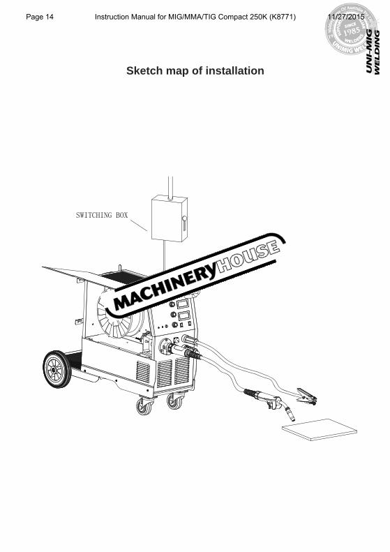
Sketch map of installation
Page 14 Instruction Manual for MIG/MMA/TIG Compact 250K (K8771) 11/27/2015
1. Working Environment.
1.1 The environment in which this welding equipment is installed must be free of grinding dust, corrosive chemicals, flammable gas or materials etc, and at no more than maximum of 80% humidity.1.2 When using the machine outdoors protect the machine from direct sun light, rain water and snow etc; the temperature of working environment should be maintained within -10°C to +40°C.1.3 Keep this equipment 30cm distant from the wall for ventilation.1.4 Ensure the working environment is well ventilated.
2. Safety Tips.
2.1 Ventilation This equipment is small-sized, compact in structure, and of excellent performance in amperage output. The fan is used to dissipate heat generated by this equipment during the welding operation.
Important: Maintain good ventilation of the louvers of this equipment. The minimum distance between this equipment and any other objects in or near the working area should be 30 cm. Good ventilation is of critical importance for the normal performance and service life of this equipment.
2.2 Thermal Overload protection. Should the machine be used to an excessive level, or in high temperature environment, poorly ventilated area or if the fan malfunctions the Thermal Over load Switch will be activated and the machine will cease to operate. Under this circumstance, leave the machine switched on to keep the built-in fan working to bring down the temperature inside the equipment. The machine will be ready for use again when the internal temperature reaches safe level.
2.3 Over-Voltage Supply Regarding the power supply voltage range of the machine, please refer to “Main parameter” table. This equipment is of automatic voltage compensation, which enables the maintaining of the voltage range within the given range. In case that the voltage of input power supply amperage exceeds the stipulated value, it is possible to cause damage to the components of this equipment. Please ensure your primary power supply is correct.
2.4 Do not come into contact with the output terminals while the machine is in operation. An electric shock may possibly occur.
CAUTION
Page 15 Instruction Manual for MIG/MMA/TIG Compact 250K (K8771) 11/27/2015
WELDING GUNS OF AUSTRALIA Pty Ltd
WWW.UNIMIG.COM.AUDisclaimer:
While the information is provided in good faith, Welding Guns Of Australia does not warrant the accuracy of information provided nor assume any legal responsibility for it or for any damage which may result from reliance on or use of it or from any
negligence of Welding Guns Of Australia or other person/s with respect to it.For further information please call Welding Guns of Australia Pty Ltd.
112 Christina Rd, Villawood NSW 2163 - PO Box 3033 Lansvale NSW 2166
MAINTENANCE
TROUBLESHOOTING
Caution: Only qualified technicians are authorized to undertake the repair of this welding equip-
ment. For your safety and to avoid Electrical Shock, please observe all safety notes and precautions detailed in this manual.
UNIMIG pursue a policy of continuous research and development, and therefore reserve the right to change the specifications, or design, without prior notice. * 2 year warranty power source.
WARRANTY• 2 Years from date of purchase.
• Welding Guns of Australia Pty Ltd warranties all goods as specified by the manufacturer of those goods. This Warranty does not cover freight or goods that have
been interfered with. All goods in question must be repaired by an authorised repair agent as appointed by this company. Warranty does not cover abuse, mis-use, accident, theft,
general wear and tear. New product will not be supplied until Welding Guns of Australia Pty Ltd has inspected product returned for warranty
and agree’s to replace product. Product will only be replaced if repair is impossible. If in doubt please ring.
WARNING: Exposure to extremely dusty, damp, or corrosive air is damaging to the welding
machine. In order to prevent any possible failure or fault of this welding equipment, clean the dust at regular intervals with clean and dry compressed air
of required pressure.Please note that: lack of maintenance can result in the cancellation of the
guarantee; the guarantee of this welding equipment will be void if the machine has been modified, attempt to take apart the machine or open the factory-made
sealing of the machine without the consent of an authorized representative of the manufacturer.
Page 16 Instruction Manual for MIG/MMA/TIG Compact 250K (K8771) 11/27/2015