
Inferior Olive simulations on Many Integrated Core platforms · DIPLWMATIKH ERGASIA thc Sof—ac P....
72
ΕΘΝΙΚΟ ΜΕΤΣΟΒΙΟ ΠΟΛΥΤΕΧΝΕΙΟ ΣΧΟΛΗ ΗΛΕΚΤΡΟΛΟΓWΝ ΜΗΧΑΝΙΚWΝ ΚΑΙ ΜΗΧΑΝΙΚWΝ ΥΠΟΛΟΓΙΣΤWΝ ΤΟΜΕΑΣ ΤΕΧΝΟΛΟΓΙΑΣ ΠΛΗΡΟΦΟΡΙΚΗΣ ΚΑΙ ΥΠΟΛΟΓΙΣΤWΝ ΕΡΓΑΣΤΗΡΙΟ ΜΙΚΡΟΫΠΟΛΟΓΙΣΤWΝ ΚΑΙ ΨΗΦΙΑΚWΝ ΣΥΣΤΗΜΑΤWΝ Inferior Olive simulations on Many Integrated Core platforms DΙΠΛWΜΑΤΙΚΗ ΕΡΓΑΣΙΑ της Σοφίας Π. Νοmικού Επιβλέπων: Dηmήτριος Ι. Σούντρης Αναπληρωτής Καθηγητής Αθήνα, Σεπτέmβριος 2015
Transcript of Inferior Olive simulations on Many Integrated Core platforms · DIPLWMATIKH ERGASIA thc Sof—ac P....
ΕΘΝΙΚΟ ΜΕΤΣΟΒΙΟ ΠΟΛΥΤΕΧΝΕΙΟΣΧΟΛΗ ΗΛΕΚΤΡΟΛΟΓΩΝ ΜΗΧΑΝΙΚΩΝ ΚΑΙ ΜΗΧΑΝΙΚΩΝ ΥΠΟΛΟΓΙΣΤΩΝ
ΤΟΜΕΑΣ ΤΕΧΝΟΛΟΓΙΑΣ ΠΛΗΡΟΦΟΡΙΚΗΣ ΚΑΙ ΥΠΟΛΟΓΙΣΤΩΝ
ΕΡΓΑΣΤΗΡΙΟ ΜΙΚΡΟΫΠΟΛΟΓΙΣΤΩΝ ΚΑΙ ΨΗΦΙΑΚΩΝ ΣΥΣΤΗΜΑΤΩΝ
Inferior Olive simulations on Many Integrated Core platforms
ΔΙΠΛΩΜΑΤΙΚΗ ΕΡΓΑΣΙΑ
της
Σοφίας Π. Νομικού
Επιβλέπων: Δημήτριος Ι. Σούντρης
Αναπληρωτής Καθηγητής
Αθήνα, Σεπτέμβριος 2015

ΕΘΝΙΚΟ ΜΕΤΣΟΒΙΟ ΠΟΛΥΤΕΧΝΕΙΟ
ΣΧΟΛΗ ΗΛΕΚΤΡΟΛΟΓΩΝ ΜΗΧΑΝΙΚΩΝ
ΚΑΙ ΜΗΧΑΝΙΚΩΝ ΥΠΟΛΟΓΙΣΤΩΝ
ΤΟΜΕΑΣ ΤΕΧΝΟΛΟΓΙΑΣ ΠΛΗΡΟΦΟΡΙΚΗΣ
ΚΑΙ ΥΠΟΛΟΓΙΣΤΩΝ
ΕΡΓΑΣΤΗΡΙΟ ΜΙΚΡΟΫΠΟΛΟΓΙΣΤΩΝ
ΚΑΙ ΨΗΦΙΑΚΩΝ ΣΥΣΤΗΜΑΤΩΝ
Inferior Olive simulations on Many Integrated Core platforms
ΔΙΠΛΩΜΑΤΙΚΗ ΕΡΓΑΣΙΑ
της
Σοφίας Π. Νομικού
Επιβλέπων: Δημήτριος Ι. Σούντρης
Αναπληρωτής Καθηγητής
Εγκρίθηκε από την τριμελή επιτροπή την -ημερομηνία εξέτασης-
........................................
Δημήτριος Ι. Σούντρης
Αναπληρωτής Καθηγητής
........................................
Κιαμάλ Ζ. Πεκμεστζή
Καθηγητής
........................................
Γιώργος Ματσοπουλος
Αναπληρωτής Καθηγητής
Αθήνα, Σεπτέμβριος 2015.
...................................
Σοφία Π. Νομικού
Διπλωματούχος Φοιτήτρια
Εθνικού Μετσόβιου Πολυτεχνείου
Copyright c© Σοφία Π. Νομικού, 2015
Με επιφύλαξη παντώς δικαιώματος.All rights reserved.
Απαγορεύεται η αντιγραφή, αποθήκευση και διανομή της παρούσας εργασίας, εξ ολοκλήρου ή
τμήματος αυτής, για εμπορικό σκοπό. Επιτρέπεται η ανατύπωση, αποθήκευση και διανομή για σκοπό
μη κερδοσκοπικό, εκπαιδευτικής ή ερευνητικής φύσης, υπο την προυπόθεση να αναφέρεται η πηγή
προέλευσης και να διατηρείται το παρόν μήνυμα. Ερωτήματα που αφορούν τη χρήση της εργασίας
για κερδοσκοποκό σκοπό πρέπει να απευθύνονται προς την συγγραφέα.
Οι απόψεις και τα συμπεράσματα που περιέχονται σε αυτό το έγγραφο εκφράζουν την συγγραφέα
και δεν πρέπει να ερμηνευθεί ότι αντιπροσωπεύουν τις επίσημες θέσεις του Εθνικού Μετσόβιου
Πολυτεχνείου.
The Intel Xeon Phi Development System used in the current thesis has been donated to
ICCS/NTUA by Intel Corporation.
i

Σύντομη περίληψη
Οι βιολογικά ακριβείς προσομοιώσεις των εγκεφαλικών κυττάρων διαδραματίζουν εναν πολυ ση-
μαντικό ρόλο στην κατανόηση της λειτουργίας του ανθρώπινου εγκεφάλου. Οι νευροεπιστήμονες τις
χρησιμοποιούν για την παρατήρηση και την πρόβλεψη της εγκεφαλικής συμπεριφοράς. Η συλλεγόμε-
νη πληροφορία συμβάλλει στις προσπάθειές τους να δημιουργήσουν συσκευές για τη βελτίωση των
συνθηκων διαβίωσης ατόμων με νευρολογικά προβλήματα. Γι αυτο το λόγο μια πληθώρα νευρικών
μοντέλων έχει αναπτυχθεί.
Στη συγκεκριμένη διπλωματική εργασία ενας βιολογικά ακριβής προσομοιωτής των κυττάρων
της κάτω ελαίας του εγκεφάλου θα μελετηθεί. Η κάτω ελαία του ανθρώπινου εγκεφάλου έχει
αποδειχθεί οτι συμμετέχει στην χωρική αντιλήψη των ανθρώπων και στην ικανότητα τους να χειρί-
ζονται μηχανήματα. Λόγω της μεγάλης πολυπλοκότητας των δικτύων αυτών των κυττάρων, τα οποία
αποτελούνται απο πολλά κύτταρα με πολλές συνδέσεις μεταξύ τους, η παραλληλοποίηση των χρησι-
μοποιούμενων προσομοιωτών εμφανίζεται ως ενα χρήσιμο εργαλείο για τη βελτίωση της απόδοσης
αυτών των εφαρμογών.
Κατα συνέπεια, το κύριο θέμα αυτής της διπλωματικής είναι η χρήση της Intel Many Inte-
grated Core (MIC) αρχιτεκτονικής για την εκτέλεση του προσομοιωτή. Δύο Xeon - Xeon Phi
μηχανήματα θα χρησιμοποιηθούν και η εφαρμογή θα γραφτεί με βάση τρία διαφορετικά προγραμ-
ματιστικά μοντέλα της αρχιτεκτονικής. Το μοντέλο ανταλλαγής μηνυμάτων, Message Passing
Interface (MPI), έχει υλοποιηθεί σε προηγούμενη εργασία [47] και χρησιμοποιείται στην τρέχουσα
διπλωματική ως η βάση για την υλοποίηση μοιραζόμενης μνήμης, με χρήση του OpenMP περιβάλ-
λοντος και για την υβριδική, Hybrid, υλοποίηση. Η υλοποίηση μοιραζόμενης μνήμης στοχεύει στη
μελέτη του παραλληλισμού της εφαρμογής και η υβριδική υλοποίηση στην συνδυαστική αξιοποίηση
των πλεονεκτημάτων της OpenMP και της MPI υλοποίησης. Τα διαφορετικά προγραμματιστικά
μοντέλα συγκρίνονται μεταξύ τους ως προς την επίδοση τους και αναδεικνύεται το πιο αποδοτικό
για την Intel Many Integrated Core (MIC) αρχιτεκτονική.
Λέξεις Κλειδιά: Κύτταρα της Κάτω Ελαίας, Xeon επεξεργαστής, Xeon Phi επεξεργαστής,
Μοντέλο ανταλλαγής μηνυμάτων, Μοντέλο κοινής μνήμης, Υβριδική υλοποίηση, συνδεσιμότητα
μεταξύ των κυττάρων
ii
Abstract
Biologically accurate simulations of brain cells play a very important role in the exploration
and understanding of human brain’s function. Neuroscientists use them in order to observe and
predict brain’s behaviour. The collected information assists their efforts in creating devices and
patents to improve the living conditions of people suffering from neurological problems. To this
direction, several neuron models have been developed.
In this thesis, a biologically accurate simulator of the Inferior Olive cells will be studied.
The Inferior Olivary body of human cerebellum has been proved to contribute to human space
perception and motor skills. Due to the significant complexity of the simulated IO cell networks,
which is due to the large number of cells and their numerous interconnections, parallelisation
of the developed brain cell simulators has emerged as a means to improve the simulation’s
performance.
Therefore, the main subject of this thesis is the porting of the simulator to an Intel Many
Integrated Core (MIC) architecture. Two Xeon - Xeon Phi machines will be utilised and three
different programming models will be studied. The Message Passing Interface (MPI) application
is used as legacy code and serves as the base for development of the OpenMP and the Hybrid
MPI/OpenMP implementation. The OpenMP code focuses on exploring the massive paralleli-
sation of the simulator and the Hybrid application aims at combining the benefits from the MPI
and the OpenMP implementations, to achieve better performance. The different programming
paradigms are compared against each other with Figures detailing each models performance
results. Finally, the most efficient programming paradigm for the simulator on the MIC archi-
tecture is concluded.
Keywords: Inferior Olive, Simulator, Xeon processor, Xeon Phi coprocessor, MPI, OpenMP,
Hybrid MPI/OpenMP, Cell connectivity
iii
Contents
1 Introduction 1
2 Prior Art 4
2.1 Neuron Modelling . . . . . . . . . . . . . . . . . . . . . . . . . . . . . . . . . . . . 4
2.2 Many-Core Platforms . . . . . . . . . . . . . . . . . . . . . . . . . . . . . . . . . 7
2.3 Programming Paradigms . . . . . . . . . . . . . . . . . . . . . . . . . . . . . . . . 10
3 Implementation Specifications 12
3.1 The Inferior Olivary Nucleus . . . . . . . . . . . . . . . . . . . . . . . . . . . . . 12
3.2 Xeon Phi Coprocessor . . . . . . . . . . . . . . . . . . . . . . . . . . . . . . . . . 17
3.2.1 System . . . . . . . . . . . . . . . . . . . . . . . . . . . . . . . . . . . . . 17
3.2.2 Developer Impressions . . . . . . . . . . . . . . . . . . . . . . . . . . . . . 19
3.3 Target platforms . . . . . . . . . . . . . . . . . . . . . . . . . . . . . . . . . . . . 21
4 MPI-based Native Implementations 23
4.1 Development Details . . . . . . . . . . . . . . . . . . . . . . . . . . . . . . . . . . 23
4.1.1 The MPI implementation . . . . . . . . . . . . . . . . . . . . . . . . . . . 23
4.1.2 The “unpacking” phase . . . . . . . . . . . . . . . . . . . . . . . . . . . . 24
4.1.3 The Hybrid implementation . . . . . . . . . . . . . . . . . . . . . . . . . . 26
4.2 Results . . . . . . . . . . . . . . . . . . . . . . . . . . . . . . . . . . . . . . . . . . 28
5 OpenMP Implementations 32
5.1 Development Details . . . . . . . . . . . . . . . . . . . . . . . . . . . . . . . . . . 32
5.1.1 Runtime Configuration . . . . . . . . . . . . . . . . . . . . . . . . . . . . . 34
5.2 Results . . . . . . . . . . . . . . . . . . . . . . . . . . . . . . . . . . . . . . . . . . 36
6 Conclusion 38
6.1 General Remarks . . . . . . . . . . . . . . . . . . . . . . . . . . . . . . . . . . . . 38
6.2 Development Challenges . . . . . . . . . . . . . . . . . . . . . . . . . . . . . . . . 39
6.3 Future Work . . . . . . . . . . . . . . . . . . . . . . . . . . . . . . . . . . . . . . 39
iv
List of Figures
1 Επίπεδα αφαίρεσης στα νευρικά μοντέλα . . . . . . . . . . . . . . . . . . . . . . . . . viii
2 Η ταξονομία του Flynn για τις πολυπύρηνες αρχιτεκτονικές [44] . . . . . . . . . . . . . . x
3 Το χρησιμοποιούμενο μοντέλο για τα νευρικά κύτταρα[36] . . . . . . . . . . . . . . . . . xii
4 Η μορφή του αρχείου εξόδου του κώδικα συνδεσιμότητας . . . . . . . . . . . . . . . . . xiii
5 Διάγραμμα ροής του κώδικα παραγωγής του αρχείου συνδεσιμότητας . . . . . . . . . . . xiv
6 Τυπική πλατφόρμα της αρχιτεκτονικής . . . . . . . . . . . . . . . . . . . . . . . . . . xv
7 Δομές που χρησιμοποιούνται στη διαδικασία ξεπακεταρίσματος . . . . . . . . . . . . . . xvii
8 Η δομή που περιέχει τις παραμέτρους των κυττάρων . . . . . . . . . . . . . . . . . . . . xvii
9 Διάγραμμα ροής της φάσης ξεπακεταρίσματος . . . . . . . . . . . . . . . . . . . . . . . xix
10 Αποτελέσματα εκτέλεσης της MPI υλοποίησης στον Xeon Phi επεξεργαστή . . . . . . . xx
11 Αποτελέσματα εκτέλεσης της υβριδικής υλοποίησης στον Xeon επεξεργαστή . . . . . . . xx
12 Αποτελέσματα εκτέλεσης της υβριδικής υλοποίησης στον Xeon Phi επεξεργαστή . . . . . xxi
13 Αποτελέσματα εκτέλεσης της OpenMP υλοποίησης . . . . . . . . . . . . . . . . . . . . xxiii
2.1 Levels of detail in neuron models . . . . . . . . . . . . . . . . . . . . . . . . . . . . 5
2.2 Flynn’s taxonomy for multi-core architectures [44] . . . . . . . . . . . . . . . . . . . . 8
2.3 Distributed Memory architecture [26] . . . . . . . . . . . . . . . . . . . . . . . . . . 9
2.4 Shared Memory architecture [26] . . . . . . . . . . . . . . . . . . . . . . . . . . . . . 9
3.1 Neuron Compartmental Model [36] . . . . . . . . . . . . . . . . . . . . . . . . . . . . 13
3.2 Brief presentation of dataflow between simulation steps [47] . . . . . . . . . . . . . . . 14
3.3 Flow diagram for the cell generator code . . . . . . . . . . . . . . . . . . . . . . . . . 15
3.4 The formatting of data in the conductivity file . . . . . . . . . . . . . . . . . . . . . . 16
3.5 Xeon processors and Xeon Phi coprocessors combined in a platform . . . . . . . . . . . 17
3.6 Architecture Overview of a MIC architecture core [34] . . . . . . . . . . . . . . . . . . 18
3.7 Software Stack [34] . . . . . . . . . . . . . . . . . . . . . . . . . . . . . . . . . . . . 19
4.1 Structures used in the unpacking phase . . . . . . . . . . . . . . . . . . . . . . . . . 25
4.2 The cell parameters structure . . . . . . . . . . . . . . . . . . . . . . . . . . . . . . 25
4.3 Flow diagram of the unpacking phase . . . . . . . . . . . . . . . . . . . . . . . . . . 27
v

4.4 Execution Results of the MPI implementation on Xeon Phi coprocessor . . . . . . . . . 29
4.5 Execution Results of the Hybrid implementation on Xeon processor . . . . . . . . . . . 29
4.6 Execution Results of the Hybrid implementation on Xeon Phi coprocessor . . . . . . . . 30
5.1 Execution Results of the OpenMP implementation . . . . . . . . . . . . . . . . . . . . 37
vi

Εκτεταμένη Περίληψη
Οι βιολογικά ακριβείς προσομοιώσεις των εγκεφαλικών κυττάρων διαδραματίζουν εναν πολυ ση-
μαντικό ρόλο στην κατανόηση της λειτουργίας του ανθρώπινου εγκεφάλου. Οι νευροεπιστήμονες τις
χρησιμοποιούν για την παρατήρηση και την πρόβλεψη της εγκεφαλικής συμπεριφοράς. Η συλλεγόμε-
νη πληροφορία συμβάλλει στις προσπάθειές τους να δημιουργήσουν συσκευές για τη βελτίωση των
συνθηκων διαβίωσης ατόμων με νευρολογικά προβλήματα. Γι αυτο το λόγο μια πληθώρα νευρικών
μοντέλων έχει αναπτυχθεί.
Στη συγκεκριμένη διπλωματική εργασία ενας βιολογικά ακριβής προσομοιωτής των κυττάρων
της κάτω ελαίας του εγκεφάλου θα μελετηθεί. Η κάτω ελαία του ανθρώπινου εγκεφάλου έχει
αποδειχθεί οτι συμμετέχει στην χωρική αντιλήψη των ανθρώπων και στην ικανότητα τους να χειρί-
ζονται μηχανήματα. Λόγω της μεγάλης πολυπλοκότητας των δικτύων αυτών των κυττάρων, τα οποία
αποτελούνται απο πολλά κύτταρα με πολλές συνδέσεις μεταξύ τους, η παραλληλοποίηση των χρησι-
μοποιούμενων προσομοιωτών εμφανίζεται ως ενα χρήσιμο εργαλείο για τη βελτίωση της απόδοσης
αυτών των εφαρμογών.
Κατα συνέπεια, το κύριο θέμα αυτής της διπλωματικής είναι η χρήση της Intel Many Inte-
grated Core (MIC) αρχιτεκτονικής για την εκτέλεση του προσομοιωτή. Δύο Xeon - Xeon Phi
μηχανήματα θα χρησιμοποιηθούν και η εφαρμογή θα γραφτεί με βάση τρία διαφορετικά προγραμ-
ματιστικά μοντέλα της αρχιτεκτονικής. Το μοντέλο ανταλλαγής μηνυμάτων, Message Passing
Interface (MPI), έχει υλοποιηθεί σε προηγούμενη εργασία [47] και χρησιμοποιείται στην τρέχουσα
διπλωματική ως η βάση για την υλοποίηση μοιραζόμενης μνήμης, με χρήση του OpenMP περιβάλ-
λοντος και για την υβριδική, Hybrid, υλοποίηση. Η υλοποίηση μοιραζόμενης μνήμης στοχεύει στη
μελέτη του παραλληλισμού της εφαρμογής και η υβριδική υλοποίηση στην συνδυαστική αξιοποίηση
των πλεονεκτημάτων της OpenMP και της MPI υλοποίησης. Τα διαφορετικά προγραμματιστικά
μοντέλα συγκρίνονται μεταξύ τους ως προς την επίδοση τους και αναδεικνύεται το πιο αποδοτικό
για την Intel Many Integrated Core (MIC) αρχιτεκτονική.
vii
1. Νευρικά Μοντέλα Προσομοίωσης
Οι προσομοιώσεις των εγκεφαλικών κυττάρων βασίζονται σε νευρικά μοντέλα που έχουν ανα-
πτυχθεί. Λόγω της πολυπλοκότητας των εγκεφαλικών φαινομένων και των ποικίλων λανθάνοντων
διαδικασιών που λαμβάνουν χώρα για την υλοποίηση οποιασδήποτε ενέργειας στον ανθρώπινο εγκέ-
φαλο, τα μοντέλα χωρίζονται σε διαφορετικά επίπεδα αφαίρεσης [7].
Υπάρχουν δύο βασικές κατηγορίες νευρικών μοντέλων [7]:
• Συμβατικά μοντέλα: Τα μοντέλα αυτα στοχεύουν στην ανάλυση των νευρικών φαινο-
μένων με βάση τους νευρολογικούς μηχανισμούς που πιθανώς οδηγούν σε αυτά. Ποσοτικο-
ποιούνται με χρήση μαθηματικών εξισώσεων για τον έλεγχο της ακρίβειάς τους.
• Υπολογιστικά μοντέλα: Αυτή η οπτική θεωρεί τις λειτουργίες του εγκεφάλου σαν υπο-
λογιστικές διαδικασίες που ερμηνεύουν τη συνολική λειτουργία των νευρολογικών τμημάτων
του για την ολοκλήρωση μιας λειτουργίας [22, 25].
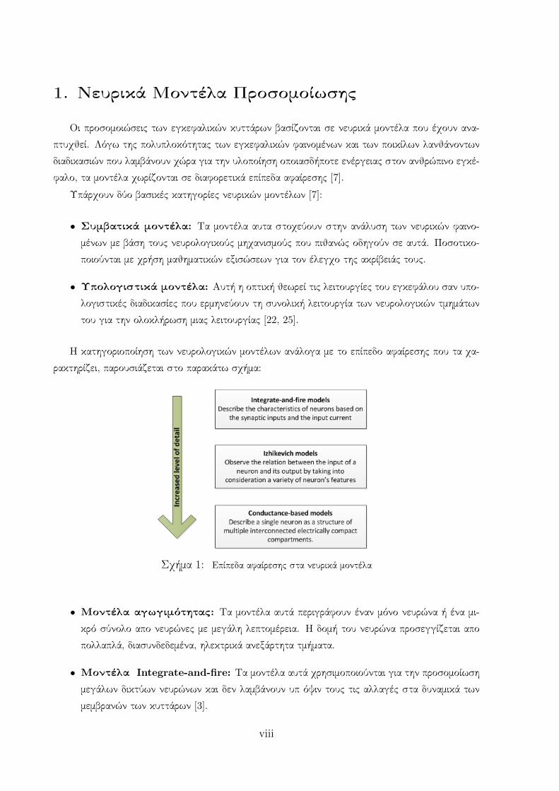
Η κατηγοριοποίηση των νευρολογικών μοντέλων ανάλογα με το επίπεδο αφαίρεσης που τα χα-
ρακτηρίζει, παρουσιάζεται στο παρακάτω σχήμα:
Σχήμα 1: Επίπεδα αφαίρεσης στα νευρικά μοντέλα
• Μοντέλα αγωγιμότητας: Τα μοντέλα αυτά περιγράφουν έναν μόνο νευρώνα ή ένα μι-
κρό σύνολο απο νευρώνες με μεγάλη λεπτομέρεια. Η δομή του νευρώνα προσεγγίζεται απο
πολλαπλά, διασυνδεδεμένα, ηλεκτρικά ανεξάρτητα τμήματα.
• Μοντέλα Integrate-and-fire: Τα μοντέλα αυτά χρησιμοποιούνται για την προσομοίωση
μεγάλων δικτύων νευρώνων και δεν λαμβάνουν υπ όψιν τους τις αλλαγές στα δυναμικά των
μεμβρανών των κυττάρων [3].
viii

• Μοντέλα Izhikevich: Τα μοντέλα αυτά μελετούν τη συσχέτιση μεταξύ της εξόδου και
της εισόδου ενος νευρώνα σα να ήταν ένα μαύρο κουτί. Συνδυάζουν την αποδοτικότητα των
Integrate-and-fire μοντέλων και το υψηλό επίπεδο ανάλυσης των μοντέλων αγωγιμότητας
[9].
2. Πολυεπεξεργαστικές Πλατφόρμες
Η δεύτερη βασική παράμετρος στην παρούσα διπλωματική εργασία έιναι οι πολυεπεξεργαστικές
πλατφόρμες. Τις τελευταίες δεκαετίες, ο Νόμος του Moore επικρατούσε ως η βασική παράμετρος
καθορισμού της εξέλιξης των υπολογιστικών συστημάτων και των επιδόσεων τους [35]. Σύμφωνα
με αυτόν, ο αριθμός των τρανζίστορ πάνω στο chip διπλασιάζεται κάθε 18 μήνες, και ανάλο-
γα μεταβάλεται και η επίδοση της μονονηματικής εκτέλεσης των υπολογιστικών συστημάτων. Τα
επιπλέον τρανζίστορ χρησιμοποιήθηκαν απο τους αρχιτέκτονες υπολογιστών για την αύξηση του πα-
ραλληλισμού επιπέδου εντολών κατασκευάζοντας πιο πολυεπίπεδα pipelines , υψηλότερες ταχύτητες
ρολογιού, επεξεργαστές με out of order εκτέλεση, καλύτερους προβλέπτες αλμάτων, πολυβαθμωτές
αρχιτεκτονικές, και για ποικίλες άλλες βελτιώσεις στο επίπεδο του συστήματος. Στην αρχή όμως
του 21ου αιώνα, η τεχνολογική κοινότητα αντιλήφθηκε οτι οι τεχνολογικές εξελίξεις δεν μπορούσαν
πλέον να ακολουθήσουν τον Νόμο του Moore. Το μέγεθος των τρανζίστορ δεν ήταν δυνατό να
μειωθεί περισσότερο αφού είχε ξεπεραστεί το όριο της θερμότητας που μπορεί να αντέξει ενα τρανζί-
στορ χωρίς την εμφάνιση προβλημάτων διαρροής ρεύματος. Κατα συνέπεια, τα επιπλέον τρανζίστορ
δεν μπορούσαν να αξιοποιηθούν για την βελτίωση της μονονηματικής εκτέλεσης των υπολογιστικών
συστημάτων [44].
Λαμβάνοντας υπ όψιν αυτά τα δεδομένα, η τεχνολογική κοινότητα στράφηκε σε ποικίλες προσεγ-
γίσεις για τη διατήρηση της μέχρι τότε αυξανόμενης επίδοσης των υπολογιστικών συστημάτων. Ο
ταυτόχρονος πολυνηματισμός , Simultaneous Multi-threading (SMT), υπήρξε μια απο τις πρώτες
πιθανές λύσεις. Αυτή η προσέγγιση κάνει έναν φυσικό επεξεργαστή να εμφανίζεται σαν πολλα-
πλοί λογικοί επεξεργαστές απο τη σκοπιά του λογισμικού, αφού πολλαπλά νήματα μοιράζονται τους
επεξεργαστικούς πόρους του φυσικού επεξεργαστή. Τα νήματα δημιουργούνται και η εκτέλεση
τους οργανώνεται ανάλογα με τη διαθεσιμότητα των επεξεργαστικών πόρων. Η επόμενη λογική
προσέγγιση ήταν η δημιουργία των πολυεπεξεργαστικών ψηφίδων, Chip Multiprocessors (CMP),
που συνέβαλαν καθοριστικά στην αύξηση της επίδοσης των υπολογιστικών συστημάτων. Οι κατα-
σκευαστές επεξεργαστών δημιούργησαν πολυπύρηνους επεξεργαστές υλοποιώντας δύο ή παραπάνω
υπολογιστικούς πυρήνες στο ίδιο κομμάτι πυριτίου. Οι διαφορετικοί υπολογιστικοί πυρήνες διαθέ-
τουν τους δικούς τους εκτελεστικούς και αρχιτεκτονικούς πόρους και μπορούν να μοιράζονται μια
μεγάλη κρυφή μνήμη υλοποιημένη πάνω στο πυρίτιο. Οι πυρήνες μπορούν να εφαρμόζουν και ταυ-
τόχρονο πολυνηματισμό προκειμένου να αυξήσουν τον αριθμό των λογικών επεξεργαστών σε δύο
φορές τον αριθμό των φυσικών επεξεργαστών [44, 12].
ix
Το επόμενο βήμα για τα υπολογιστικά συστήματα ήταν ο συνδυασμός πολλών CMP επεξερ-
γαστών σε ένα σύστημα, γεγονός που οδήγησε στη γέννηση των πολυπύρηνων συστημάτων. Οι
πολυπύρηνες πλατφόρμες χρησιμοποιούνται ευρύτατα σε μια πληθώρα υπολογιστικά απαιτητικών
εφαρμογών [21, 6].
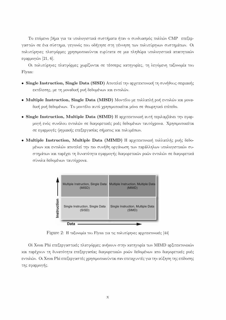
Οι πολυπύρηνες πλατφόρμες χωρίζονται σε τέσσερις κατηγορίες, τη λεγόμενη ταξονομία του
Flynn:
• Single Instruction, Single Data (SISD) Αποτελεί την αρχιτεκτονική τη συνήθους σειριακής
εκτέλεσης, με τη μοναδική ροή δεδομένων και εντολών.
• Multiple Instruction, Single Data (MISD) Μοντέλο με πολλαπλή ροή εντολών και μονα-
δική ροή δεδομένων. Το μοντέλο αυτό χρησιμοποιείται μόνο σε θεωρητικό επίπεδο.
• Single Instruction, Multiple Data (SIMD) Η αρχιτεκτονική αυτή περιλαμβάνει την εφαρ-
μογή ενός συνόλου εντολών σε διαφορετικές ροές δεδομένων ταυτόχρονα. Χρησιμοποιείται
σε εφαρμογές ψηφιακής επεξεργασίας σήματος και πολυμέσων.
• Multiple Instruction, Multiple Data (MIMD) Η αρχιτεκτονική πολλαπλής ροής δεδο-
μένων και εντολών αποτελεί την πιο συνήθη οργάνωση των παράλληλων υπολογιστικών συ-
στημάτων και παρέχει τη δυνατότητα εφαρμογής διαφορετικών ροών εντολών σε διαφορετικά
σύνολα δεδομένων ταυτόχρονα.
Figure 2: Η ταξονομία του Flynn για τις πολυπύρηνες αρχιτεκτονικές [44]
Oi Xeon Phi επεξεργαστικές πλατφόρμες ανήκουν στην κατηγορία των MIMD αρξιτεκτονικών
και παρέχουν τη δυνατότητα επεξεργασίας διαφορετικών ροών δεδομένων απο διαφορετικές ροές
εντολών. Οι Xeon Phi επεξεργαστές χρησιμοποιούνται σαν επιταχυντές για την αύξηση της επίδοσης
της εφαρμογής.
x
3. Προγραμματιστικά Εργαλεία
Υπάρχει μεγάλη ποικιλία προγραμματιστικών εργαλείων για τις πολυεπεξεργαστικές πλατφόρ-
μες. Κάποια απο αυτά δημιουργήθηκαν αποκλειστικά για κάποιες συγκεκριμένες αρχιτεκτονικές και
κάποια άλλα έχουν γενική χρήση. Ανάλογα με την αρχιτεκτονική της πολυεπεξεργαστικής πλατ-
φόρμας ορισμένα προγραμματιστικά μοντέλα αποδεικνύονται πιο αποδοτικά απο κάποια άλλα τόσο
ως προς την επίδοση της εφαρμογής όσο και ως προς τη δυσκολία του προγραμματισμού. Παρακάτω
θα γίνει λόγος για τα πιο βασικά προγραμματιστικά εργαλεία πολυπύρηνων αρχιτεκτονικών:
• Message Passing Interface (MPI): Το μοντέλο ανταλλαγής μηνυμάτων είναι ένα προγραμ-
ματιστικό μοντέλο για τον προγραμματισμό αρχιτεκτονικών κατανεμημένης μνήμης. Κάθε
επεξεργαστής διαθέτει ιδιωτική ιεραρχία μνήμης και ειναι συνδεδεμένος με τους άλλους ε-
πεξεργαστές μέσω δικτύου διασύνδεσης. Δεν υπάρχουν μοιραζόμενα δεδομένα μεταξύ των
επεξεργαστών και για την ανταλλαγή δεδομένων απαιτούνται σαφείς κλήσεις αποστολής και
λήψης τους. Παρόλο που οι αρχιτεκτονικές κατανεμημένης μνήμης είναι δυσκολότερες στον
προγραμματισμό, εμφανίζουν μεγάλη κλιμακωσιμότητα σε χιλιάδες κόμβων και το μοντέλο
ανταλλαγής μηνυμάτων χρησιμοποιείται με μεγάλη επιτυχία στον προγραμματισμό υψηλών ε-
πιδόσεων, High Performance Computing (HPC)[50]. Το πρότυπο ανταλλαγής μηνυμάτων,
MPI Standard Library, μπορεί να χρησιμοποιηθεί σε ολες τις υπολογιστικές πλατφόρμες
υψηλής επίδοσης και υποστηρίζει τις γλώσσες προγραμματισμού C, C++ Fortran 77 και
F90 [27].
• OpenMP: Αποτελεί ένα εργαλείο προγραμματισμού για αρχιτεκτονικές μοιραζόμενης μνήμης,
στις οποίες οι επεξεργαστές έχουν έναν κοινό χώρο διευθύνσεων [40]. Στο εργαλείο αυτό
ο προγραμματιστής ορίζει ρητά τα τμήματα του κώδικα που θα εκτελεστούν παράλληλα και
ο μεταγλωττιστής του περιβάλλοντος είναι υπεύθυνος για την παραγωγή του παράλληλου
κώδικα. Οι γλώσσες προγραμματισμού που υποστηρίζονται απο το πρότυπο είναι οι C, C++
και η Fortran [50].
• Threading Building Blocks (TBBs): Αυτό το προγραμματιστικό μοντέλο είναι μια C++
template βιβλιοθήκη για παράλληλο προγραμματισμό σε αρχικτεκτονικές μοιραζόμενης μνή-
μης. Αναπτύσσεται απο την Intel R©απο το 2004 και έίναι ανοιχτού κώδικα απο το 2007.
Προσφέρει διευκολύνσεις στους προγραμματιστές αφού παρέχει μαι πληθώρα έτοιμων προς
χρήση προτύπων κώδικα και η βιβλιοθήκη υλοποιεί τον παραλληλισμό που ο προγραμματιστής
απλά αναφέρει [31].
• CUDA C: Το προγραμματιστικό αυτό εργαλείο είναι ένα περιβάλλον λογισμικού που αναπτύχθη-
κε για τη χρήση της γλώσσας C στον προγραμματισμό της CUDA αρχιτεκτονικής γενικού
σκοπού της εταιρίας NVIDIA[39]. Ο προγραμματιστής καθορίζει τα τμήματα του κώδικα που
θα εκτελεστούν στην CPU και τα τμήματα εκείνα που θα εκτελεστούν στην GPU, καθώς
xi
και τις μεταφορές των δεδομένων μεταξύ τους, γεγονός που αυξάνει την προγραμματιστική
δυσκολία.[38].
4. Τα κύτταρα της Κάτω Ελαίας του εγκεφάλου
Ο προσομοιωτής των κυττάρων της κάτω ελαίας του εγκεφάλου που χρησιμοποιείται στην πα-
ρούσα εργασία είναι ένας βιολογικά ακριβής προσομοιωτής που βασίζεται στις διαφορικές εξισώσεις
του μοντέλου των Hodgkin και Huxley [1]. Η εφαρμογή στοχεύει στην προσομοίωση ενός δικτύου
κυττάρων τα χαρακτηριστικά του οποίου καθορίζονται απο τον χρήστη. Ως είσοδος παρέχεται το
μέγεθος του δικτύου, το αρχείο συνδεσιμότητας μεταξύ των κυττάρων και ένα αρχείο με τα ρεύματα
εισόδου σε κάθε κύτταρο ανα βήμα προσομοίωσης. Οι βιολογικές παράμετροι όλου του δικτύου
υπολογίζονται κι αποθηκεύονται σε κάθε βήμα της προσομοίωσης και γι αυτό το λόγο η προσέγγιση
αυτή διαφέρει απο τις συνήθεις προσεγγίσεις που αντιμετωπίζουν τα κύτταρα σαν μαύρα κουτιά [42].
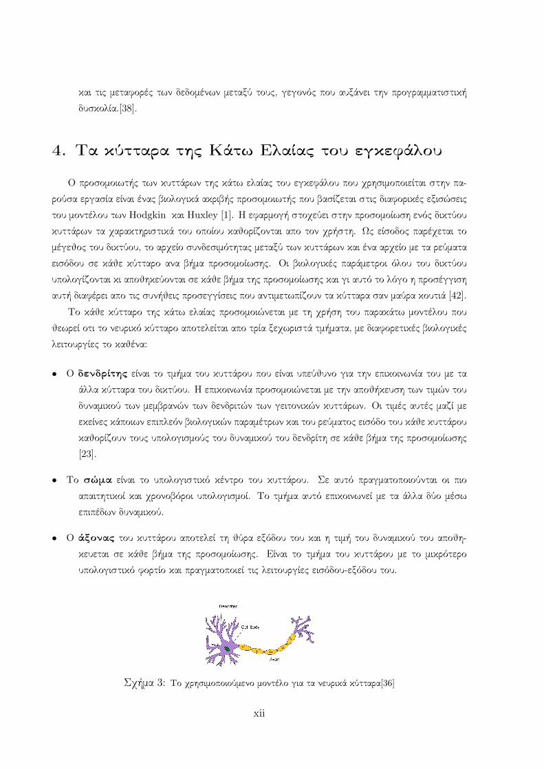
Το κάθε κύτταρο της κάτω ελαίας προσομοιώνεται με τη χρήση του παρακάτω μοντέλου που
θεωρεί οτι το νευρικό κύτταρο αποτελείται απο τρία ξεχωριστά τμήματα, με διαφορετικές βιολογικές
λειτουργίες το καθένα:
• Ο δενδρίτης είναι το τμήμα του κυττάρου που είναι υπεύθυνο για την επικοινωνία του με τα
άλλα κύτταρα του δικτύου. Η επικοινωνία προσομοιώνεται με την αποθήκευση των τιμών του
δυναμικού των μεμβρανών των δενδριτών των γειτονικών κυττάρων. Οι τιμές αυτές μαζί με
εκείνες κάποιων επιπλεόν βιολογικών παραμέτρων και του ρεύματος εισόδο του κάθε κυττάρου
καθορίζουν τους υπολογισμούς του δυναμικού του δενδρίτη σε κάθε βήμα της προσομοίωσης
[23].
• Το σώμα είναι το υπολογιστικό κέντρο του κυττάρου. Σε αυτό πραγματοποιούνται οι πιο
απαιτητικοί και χρονοβόροι υπολογισμοί. Το τμήμα αυτό επικοινωνεί με τα άλλα δύο μέσω
επιπέδων δυναμικού.
• Ο άξονας του κυττάρου αποτελεί τη θύρα εξόδου του και η τιμή του δυναμικού του αποθη-
κευεται σε κάθε βήμα της προσομοίωσης. Είναι το τμήμα του κυττάρου με το μικρότερο
υπολογιστικό φορτίο και πραγματοποιεί τις λειτουργίες εισόδου-εξόδου του.
Σχήμα 3: Το χρησιμοποιούμενο μοντέλο για τα νευρικά κύτταρα[36]
xii
Στην αρχή της προσομοίωσης η εφαρμογή δεσμέυει χώρο στη μνήμη για την αποθήκευση των
απαράιτητων παραμέτρων του κάθε κυττάρου για την προσομοίωση. Σε κάθε βήμα της προσομοίω-
σης οι δενδρίτες λαμβάνουν ως είσοδο το ρεύμα εισόδου που έχει καθοριστεί απο τον χρήστη ή ένα
σταθερό ρεύμα που έχει υλοποιηθεί μέσα στο πρόγραμμα. Στην παρούσα εργασία χρησιμοποιήθηκε
η δεύτερη μορφή είσοδου αφού ο πρωταρχικός στόχος της είναι η μελέτη της κλιμακωσιμότητας της
εφαρμογής η οποία δεν επηρεάζεται απο τη μορφή του ρεύματος εισόδου. Στη συνέχεια οι δενδρίτες
αποθηκεύουν τις τιμές των δυναμικών των δενδριτών των γειτονικών κυττάρων. Η σύνδεσεις μεταξυ
των κυττάρων του δικτύου καθορίζονται μέσω ενός αρχείου συνδεσιμότητας που καθορίζεται απο
τον χρήστη, το οποίο περιέχει την τιμή της αγωγιμότητας για κάθε σύνδεση μεταξύ δύο κυττάρων.
Σε προηγούμενη δουλειά [47] είχε υλοποιηθεί ένα απλό σχήμα συνδεσιμότητας που θεωρούσε ότι
κάθε νευρώνας συνδέεται μόνο με τους 8 άμεσους γείτονες του πάνω στο πλέγμα, με το δίκτυο
να αναπαρίσταται σαν ένας διδιάστατος πίνακας. Σε επόμενη φάση της προσομοίωσης, τα κύτταρα
ανταλλάσσουν τα δυναμικά τους και οι λαμβανόμενες τιμές αποθηκεύονται σε κατάλληλα διαμορ-
φωμένους buffers.Μετά τη λήψη των απαραίτητων τιμών κάθε τμήμα του κυττάρου υπολογίζει τη
νέα τιμή του δυναμικού του. Η τιμή του δυναμικού του άξονα κάθε κυττάρου καταγράφεται στο
αρχείο εξόδου της προσομοίωσης. Αυτή η διαδικασία επαναλαμβάνεται μέχρι να ολοκληρωθεί η
προσομοίωση.
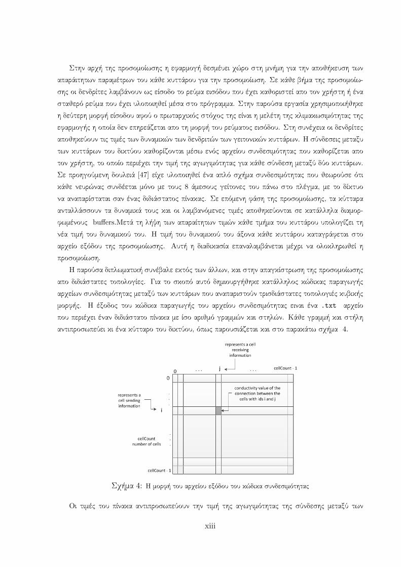
Η παρούσα διπλωματική συνέβαλε εκτός των άλλων, και στην απαγκίστρωση της προσομοίωσης
απο διδιάστατες τοπολογίες. Για το σκοπό αυτό δημιουργήθηκε κατάλληλος κώδικας παραγωγής
αρχείων συνδεσιμότητας μεταξύ των κυττάρων που αναπαριστούν τρισδιάστατες τοπολογιές κυβικής
μορφής. Η έξοδος του κώδικα παραγωγής του αρχείου συνδεσιμότητας ειναι ένα .txt αρχείο
που περιέχει έναν διδιάστατο πίνακα με ίσο αριθμό γραμμών και στηλών. Κάθε γραμμή και στήλη
αντιπροσωπεύει κι ένα κύτταρο του δικτύου, όπως παρουσιάζεται και στο παρακάτω σχήμα 4.
Σχήμα 4: Η μορφή του αρχείου εξόδου του κώδικα συνδεσιμότητας
Οι τιμές του πίνακα αντιπροσωπεύουν την τιμή της αγωγιμότητας της σύνδεσης μεταξύ των
xiii
κυττάρων που αντιστοιχούν στην εκάστοτε εξεταζόμενη γραμμή και στήλη. Μηδενική τιμή αγωγι-
μότητας σημαίνει οτι δεν υπάρχει σύνδεση μεταξύ των κυττάρων, ενώ τιμή 0.04 δείχνει την ύπαρξη
σύνδεσης και είναι η default τιμή όπως αυτή προσδιορίζεται απο το χρησιμοποιούμενο μοντέλο
νευρικών κυττάρων. Ο μόνος περιορισμός που εφαρμόζεται είναι οι τιμές της αγωγιμότητας στη
διαγώνιο του πίνακα να είναι μηδενικές αφού δεν επιτρέπεται σύνδεση ενος κυττάρου με τον εαυτό
του.
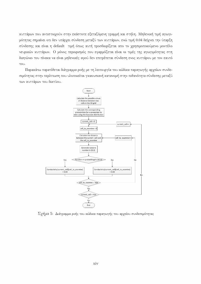
Παρακάτω παρατίθεται διάγραμμα ροής με τη λειτουργία του κώδικα παραγωγής αρχείων συνδε-
σιμότητας στην περίπτωση που υλοποιείται γκαουσιανή κατανομή στην πιθανότητα σύνδεσης μεταξύ
των κυττάρων του δικτύου.
Σχήμα 5: Διάγραμμα ροής του κώδικα παραγωγής του αρχείου συνδεσιμότητας
xiv
5. Η αρχιτεκτονικη των χρησιμοποιούμενων
συστημάτων
Στη συνέχεια θα περιγραφεί η Intel Many Integrated Core (MIC) αρχιτεκτονική η οποία είναι
και η αρχιτεκτονική των Xeon - Xeon Phi μηχανημάτων που χρησιμοποιήθηκαν σε αυτή την εργασία.
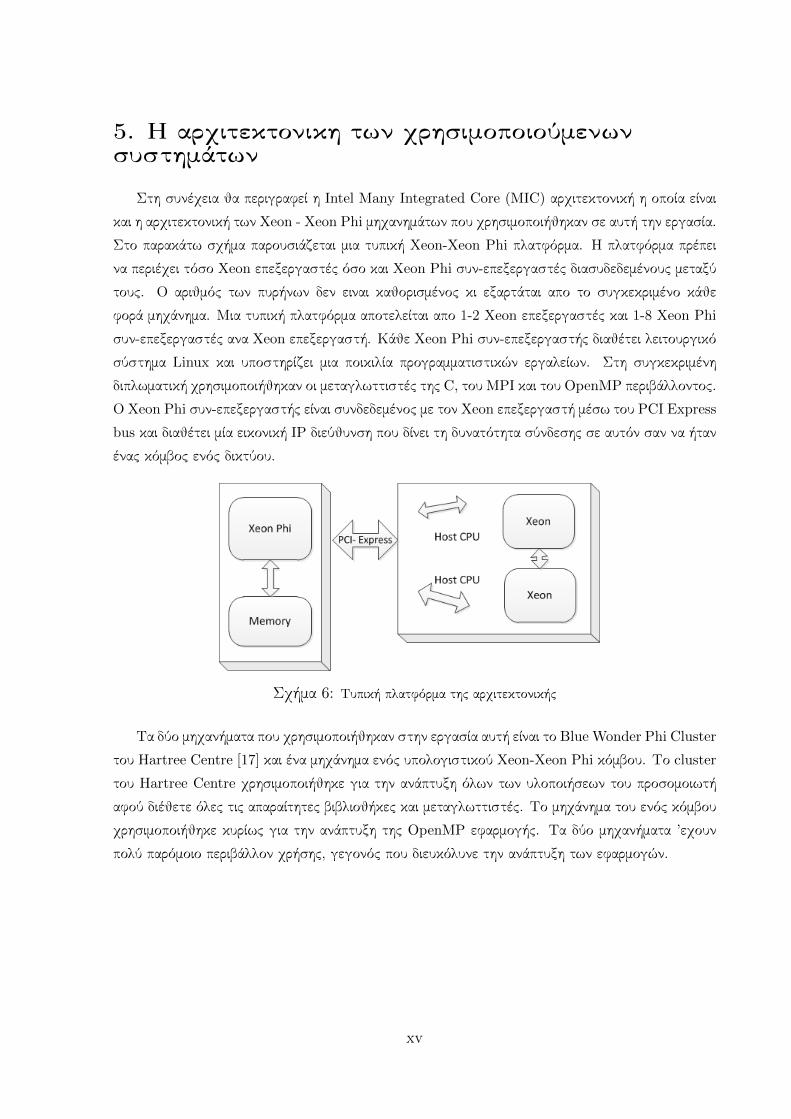
Στο παρακάτω σχήμα παρουσιάζεται μια τυπική Xeon-Xeon Phi πλατφόρμα. Η πλατφόρμα πρέπει
να περιέχει τόσο Xeon επεξεργαστές όσο και Xeon Phi συν-επεξεργαστές διασυδεδεμένους μεταξύ
τους. Ο αριθμός των πυρήνων δεν ειναι καθορισμένος κι εξαρτάται απο το συγκεκριμένο κάθε
φορά μηχάνημα. Μια τυπική πλατφόρμα αποτελείται απο 1-2 Xeon επεξεργαστές και 1-8 Xeon Phi
συν-επεξεργαστές ανα Xeon επεξεργαστή. Κάθε Xeon Phi συν-επεξεργαστής διαθέτει λειτουργικό
σύστημα Linux και υποστηρίζει μια ποικιλία προγραμματιστικών εργαλείων. Στη συγκεκριμένη
διπλωματική χρησιμοποιήθηκαν οι μεταγλωττιστές της C, του MPI και του OpenMP περιβάλλοντος.
Ο Xeon Phi συν-επεξεργαστής είναι συνδεδεμένος με τον Xeon επεξεργαστή μέσω του PCI Express
bus και διαθέτει μία εικονική IP διεύθυνση που δίνει τη δυνατότητα σύνδεσης σε αυτόν σαν να ήταν
ένας κόμβος ενός δικτύου.
Σχήμα 6: Τυπική πλατφόρμα της αρχιτεκτονικής
Τα δύο μηχανήματα που χρησιμοποιήθηκαν στην εργασία αυτή είναι το Blue Wonder Phi Cluster
του Hartree Centre [17] και ένα μηχάνημα ενός υπολογιστικού Xeon-Xeon Phi κόμβου. Το cluster
του Hartree Centre χρησιμοποιήθηκε για την ανάπτυξη όλων των υλοποιήσεων του προσομοιωτή
αφού διέθετε όλες τις απαραίτητες βιβλιοθήκες και μεταγλωττιστές. Το μηχάνημα του ενός κόμβου
χρησιμοποιήθηκε κυρίως για την ανάπτυξη της OpenMP εφαρμογής. Τα δύο μηχανήματα ’εχουν
πολύ παρόμοιο περιβάλλον χρήσης, γεγονός που διευκόλυνε την ανάπτυξη των εφαρμογών.
xv
6. Η Υβριδική υλοποίηση
Η Υβριδική υλοποίηση προκύπτει απο την MPI υλοποίηση που χρησιμοποιήθηκε σε αυτή την
εργασία ως προυπάρχων κώδικας [49]. Συγκεκριμένα, σειριακά τμήματα της MPI υλοποίησης εκτε-
λούνται απο OpenMP threads στην υβριδικη προκειμένου να αυξηθεί η επίδοση της εκτέλεσης της
εφαρμογής.
Η βασική αλλαγή που πραγματοποιήθηκε στην MPI υλοποίηση προκειμένου να μπορέσει να μετα-
τραπεί στην υβριδική αφορά τη λειτουργία του κυρίως βρόχου της προσομοίωσης που παρουσιάζεται
παρακάτω με τη μορφή ψευδοκώδικα.
Algorithm 1 The main loop of the simulation in the MPI implementation
1: for sim step = 0 : max do2: MPI Isend();3: MPI Irecv();4: MPI sync();5: uncpack voltages6: for cell = 0 : cellCount do7: compute new dendritic voltage()8: compute new somatic voltage()9: compute new axonal voltage()
10: end for11: end for
Σε κάθε βήμα της προσομοίωσης οι πυρήνες που χρησιμοποιούνται ανταλλάσσουν τις τιμές
δυναμικού των κυττάρων τους (γραμμές 2,3,4), συγκεντρώνουν τις απαραίτητες πληροφορίες απο τα
γειτονικά κύτταρα (γραμμή 5) και το εξωτερικό περιβάλλον, εάν υπάρχει αρχείο εισόδου ρεύματος,
και υπολογίζουν εκ νέου τις παραμέτρους των κυττάρων τους (γραμμές 7,8,9). Η ανταλλαγή των
δυναμικών γίνεται με χρήση των MPI εντολών για αποστολή και λήψη δεδομένων.
Για τη βελτίωση της επίδοσης της προσομοίωσης τα σειριακά τμήματα του παραπάνω κώδικα
όπως η διαδικασία ξεπακεταρίσματος των τιμών δυναμικου που λαμβάνει ο κάθε πυρήνας καθώς
και οι διαδικασίες του εκ νέου υπολογισμού των δυναμικών των κυττάρων θα εκτελεστούν απο
παράλληλα νήματα.
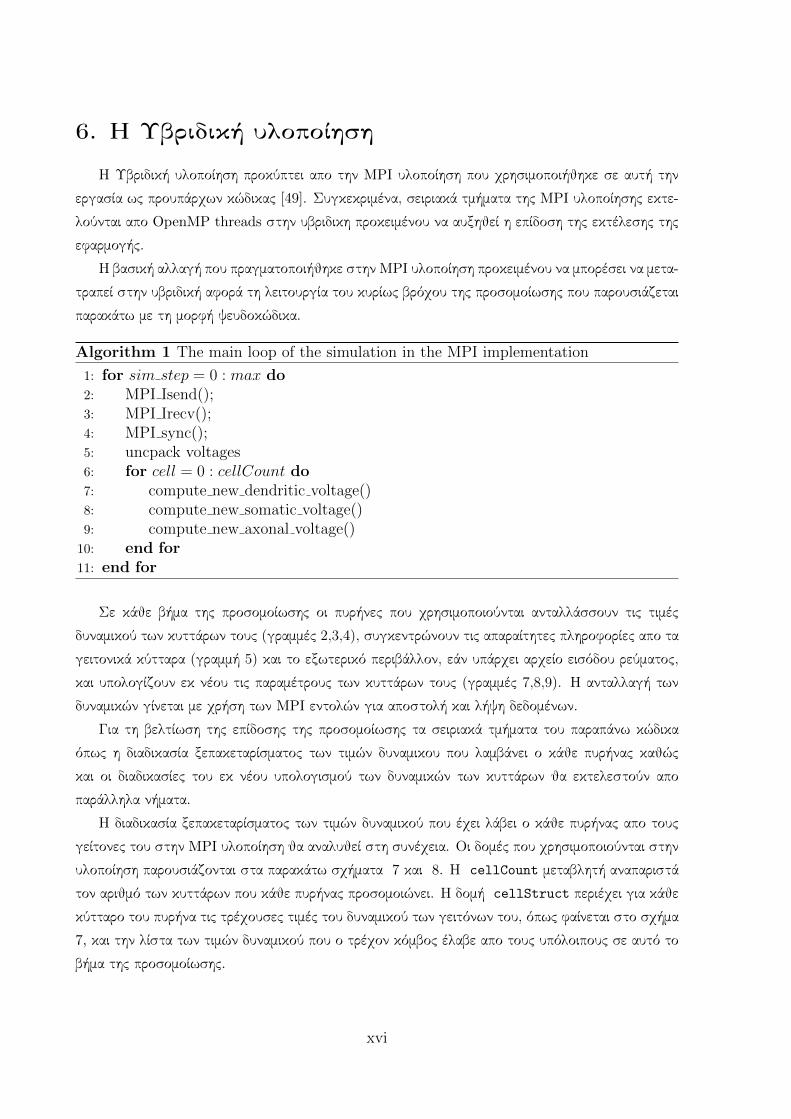
Η διαδικασία ξεπακεταρίσματος των τιμών δυναμικού που έχει λάβει ο κάθε πυρήνας απο τους
γείτονες του στην MPI υλοποίηση θα αναλυθεί στη συνέχεια. Οι δομές που χρησιμοποιούνται στην
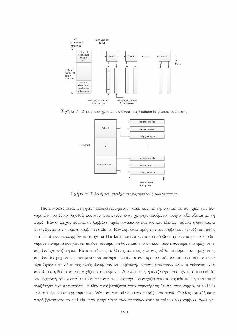
υλοποίηση παρουσιάζονται στα παρακάτω σχήματα 7 και 8. Η cellCount μεταβλητή αναπαριστά
τον αριθμό των κυττάρων που κάθε πυρήνας προσομοιώνει. Η δομή cellStruct περιέχει για κάθε
κύτταρο του πυρήνα τις τρέχουσες τιμές του δυναμικού των γειτόνων του, όπως φαίνεται στο σχήμα
7, και την λίστα των τιμών δυναμικού που ο τρέχον κόμβος έλαβε απο τους υπόλοιπους σε αυτό το
βήμα της προσομοίωσης.
xvi
Σχήμα 7: Δομές που χρησιμοποιούνται στη διαδικασία ξεπακεταρίσματος
Σχήμα 8: Η δομή που περιέχει τις παραμέτρους των κυττάρων
Πιο συγκεκριμένα, στη φάση ξεπακεταρίσματος, κάθε κόμβος της λίστας με τις τιμές των δυ-
ναμικών που έξουν ληφθεί, που αντιπροσωπεύει εναν χρησιμοποιούμενο πυρήνα, εξετάζεται με τη
σειρά. Εάν ο τρέχον κόμβος δε λαμβάνει τιμές δυναμικού απο τον υπο εξέταση κόμβο η διαδικασία
συνεχίζει με τον επόμενο κόμβο στη λίστα. Εάν λαμβάνει τιμές απο τον κόμβο που εξετάζεται, κάθε
cell id που περιλαμβάνεται στην cells to receive λίστα του κόμβου της λίστας με τα λαμβα-
νόμενα δυναμικά αναφέρεται σε ένα κύτταρο, το δυναμικό του οποίου κάποια κύτταρα του τρέχοντος
κόμβου έχουν ζητήσει. Κατα συνέπεια, οι λίστες με τους γείτονες κάθε κυττάρου του τρέχοντος
κόμβου διατρέχονται προκειμένου να καθοριστεί εάν το κύτταρο του κόμβου που εξετάζεται τωρα
είχε ζητήσει τη λήψη της τιμής δυναμικού υπο εξέταση. ΄Οταν εξεταστούν όλοι οι γείτονες ενός
κυττάρου, η διαδικασία συνεχίζει στο επόμενο. Διαφορετικά, η αναζήτηση για την τιμή του cell id
υπο εξέταση στη λίστα με τους γείτονες του κυττάρου συνεχίζει απο το σημείο που η τελευταία
αναζήτηση είχε σταματήσει. Η ιδέα αυτή βασίζεται στην παρατήρηση ότι σε κάθε κόμβο, τα cell ids
των κυττάρων που προσομοιώνει βρίσκονται αποθηκευμένα σε αύξουσα σειρά. Ομοίως, σε αύξουσα
σειρά βρίσκονται τα cell ids μέσα στην λίστα των γειτόνων κάθε κυττάρου του κόμβου, αλλα και
xvii

τα ids των κυττάρων στους κόμβους της λίστας με τα δυναμικά προς λήψη απο τον τρέχων πυρήνα.
Συνεπώς, η αναζήτηση μπορεί να περιοριστεί μόνο στα τμήματα των λιστών που δεν έξουν εξεταστεί
μέχρτι στιγμής, σε κάθε στιγμή.
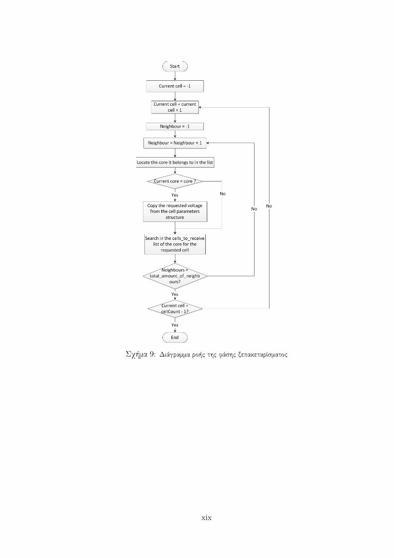
Η υλοποίηση αυτή είναι αρκετά πολύπλοκη και δεν μπορεί εύκολα να εκτελεστεί παράλληλα. Προς
αυτή την κατεύθυνση πραγματοποιηθηκε αλλαγή της φάσης ξεπακεταρίσματος. Η νέα προσέγγιση
παρουσιάζεται στο διάγραμμα ροής της εικόνα 9.
Με την αλλαγή της φάσης ξεπακεταρίσματος είναι εύκολο να υλοποιηθεί παράλληλα ο κύριος
βρόχος της προσομοίωσης. Συγκεκριμένα, με τη νέα προσέγγιση, αντί να ξεκινάει η διαδικασία
απο τους κόμβους της λίστας με τα δυναμικά προς λήψη, ξεκινάει απο τα κύτταρα του τρέχοντος
πυρήνα. Το πλεονέκτημα αυτής της προσέγγισης είναι ότι η φάση ξεπακεταρίσματος μπορεί πλέον
να υλοποιηθεί παράλληλα και να συγχωνευτεί σε έναν επαναληπτικό βρόχο με τους υπολογισμούς
των νέων τιμών των δυναμικών. Ο νέος κώδικας του βήματος προσομοίωσης παρουσιάζεται στη
συνέχεια με τη μορφή ψευδοκώδικα.
Algorithm 2 The main loop of the simulation in the Hybrid implementation
1: for sim step = 0 : max do2: MPI Isend();3: MPI Irecv();4: MPI sync();5: #pragma omp parallel for6: for cell = 0 : cellCount do7: unpack voltages8: compute new dendritic voltage()9: compute new somatic voltage()
10: compute new axonal voltage()11: end for12: end for
xviii
Σχήμα 9: Διάγραμμα ροής της φάσης ξεπακεταρίσματος
xix
Αποτελέσματα
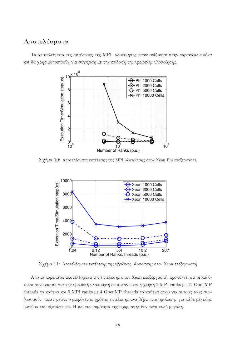
Τα αποτελέσματα της εκτέλεσης της MPI υλοποίησης παρουσιάζονται στην παρακάτω εικόνα
και θα χρησιμοποιηθούν για σύγκριση με την επίδοση της υβριδικής υλοποίησης.
100
101
102
0
2
4
6
8
10x 10
6
Number of Ranks (p.u.)
Exe
cu
tio
n T
ime
/Sim
ula
tio
n s
tep
(us)
Phi 1000 CellsPhi 2000 CellsPhi 5000 CellsPhi 10000 Cells
Σχήμα 10: Αποτελέσματα εκτέλεσης της MPI υλοποίησης στον Xeon Phi επεξεργαστή
1:24 2:12 5:4 10:2 20:10
2000
4000
6000
8000
10000
Number of Ranks:Threads (p.u.)
Exe
cu
tio
n T
ime
/Sim
ula
tio
n s
tep
(us)
Xeon 1000 CellsXeon 2000 CellsXeon 5000 CellsXeon 10000 Cells
Σχήμα 11: Αποτελέσματα εκτέλεσης της υβριδικής υλοποίησης στον Xeon επεξεργαστή
Απο τα παραπάνω αποτελέσματα της εκτέλεσης στον Xeon επεξεργαστή, προκύπτει οτι οι καλύ-
τεροι συνδυασμόι για την υβριδική υλοποίηση σε αυτόν είναι η χρήση 2 MPI ranks με 12 OpenMP
threads το καθένα και 5 MPI ranks με 4 OpenMP threads το καθένα αφού για αυτούς τους συν-
δυασμούς παρατηρείται ο μικρότερος χρόνος εκτέλεσης ανα βήμα προσομοίωσης για κάθε μέγεθος
δικτύου που εξετάστηκε. Η κλιμακωσιμότητα της εφαρμογής δεν ειναι πολύ μεγάλη.
xx
1:240 2:120 5:48 10:24 20:12 50:40
0.5
1
1.5
2x 10
5
Number of Ranks:Threads (p.u.)
Exe
cu
tio
n T
ime
/Sim
ula
tio
n s
tep
(us)
Phi 1000 CellsPhi 2000 CellsPhi 5000 CellsPhi 10000 Cells
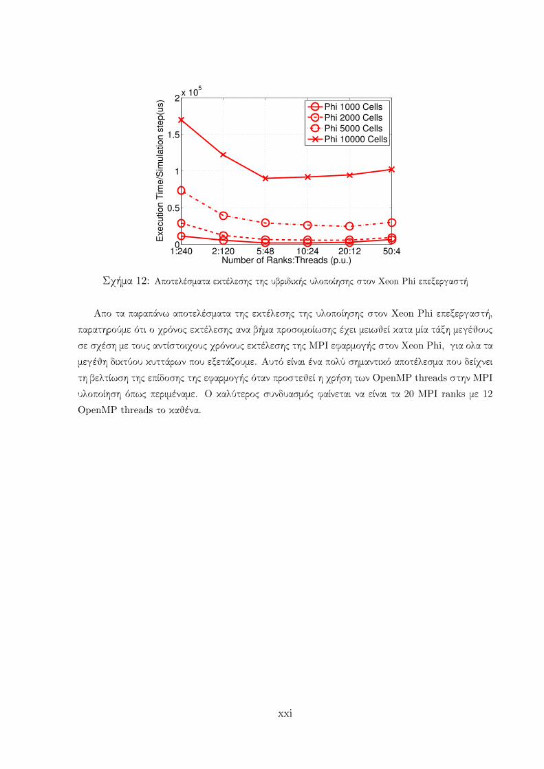
Σχήμα 12: Αποτελέσματα εκτέλεσης της υβριδικής υλοποίησης στον Xeon Phi επεξεργαστή
Απο τα παραπάνω αποτελέσματα της εκτέλεσης της υλοποίησης στον Xeon Phi επεξεργαστή,
παρατηρούμε ότι ο χρόνος εκτέλεσης ανα βήμα προσομοίωσης έχει μειωθεί κατα μία τάξη μεγέθους
σε σχέση με τους αντίστοιχους χρόνους εκτέλεσης της MPI εφαρμογής στον Xeon Phi, για ολα τα
μεγέθη δικτύου κυττάρων που εξετάζουμε. Αυτό είναι ένα πολύ σημαντικό αποτέλεσμα που δείχνει
τη βελτίωση της επίδοσης της εφαρμογής όταν προστεθεί η χρήση των OpenMP threads στην MPI
υλοποίηση όπως περιμέναμε. Ο καλύτερος συνδυασμός φαίνεται να είναι τα 20 MPI ranks με 12
OpenMP threads το καθένα.
xxi
7. Η υλοποίηση μοιραζόμενης μνήμης
Η υλοποίηση μοιραζόμενης μνήμης με χρήση του OpenMP περιβάλλοντος, προέκυψε απο την
μονονηματική υλοποίηση που παρήχθηκε απο την MPI υλοποίηση. Οι δυο βασικές αλλαγές που
έγιναν στον MPI κώδικα για να μετατραπεί σε μονονηματικό είναι οι παρακάτω.
• Η αρχική φάση στην MPI υλοποίηση κατα την οποία κατασκευάζεται η λίστα επικοινωνίας
ενος κόμβου με τους γείτονες του προκειμένου να ανταλλάσσει τα απαραίτητα δεδομένα κατα
τη διάρκεια της προσομοίωσης, μπορεί να απλοποιηθεί. Αντι να δημιουργούνται δυο λίστες,
μια για τους κόμβους απο τους οποίους ο τρέχον κόμβος θα λάβει δεδομένα και μια για εκεί-
νους στους οποίους θα στείλει δεδομένα, με χρήση των κοινών μεταβλητών στη μοιραζόμενη
μνήμη, χρεαζεται μονο να δημιουργηθεί η λίστα για τους κόμβους απο τους οποίους λαμβάνει
δεδομένα ο τρέχον κόμβος αφου η αποστολή τους μπορεί να γίνει με άμεση ανάγνωση των
επιθυμητών τιμών απο τις μοιραζόμενες μεταβλητές μεταξύ των κόμβων. Η αρχική αυτή φάση
παρουσιάζεται στον παρακάτω ψευδοκώδικα:
Algorithm 3 The Initial Communication phase in the OpenMP implementation
1: for row = 0 : cellsNumb do . a row is a cell sending voltages2: for col = 0 : cellsNumb do . a column is a cell possibly receiving voltages3: cond value = read conductivity value4: if cond value == 0 then5: ; . no connection exists between the cells6: [7: else8: cellStr[col].neigh ids = alloc one more space(cellStr[col].neigh ids)9: cellStr[col].neigh ids[total neigh] = row
10: cellStr[col].cond = alloc one more space(cellStr[col].cond)11: cellStr[col].cond[total neigh] = cond value12: cellStr[col].neigh volts = alloc one more space(cellStr[col].neigh volts)13: total neigh[col] + +14: ]15: end if16: end for17: end for
Η δομή cellStr περιέξει τις τρέχουσες τιμές των παραμέτρων που περιγράφουν την κα΄τα-
σταση του κάθε κυττάρου.
• Η δεύτερη αλλάγη πραγματοποιήθηκε στον κώδικα που εκτελείται σε κάθε βήμα της προ-
σομοίωσης. Οι δυο φάσεις που υπάρχουν, η φάση επικοινωνίας και η φάση υπολογισμών,
μπορούν να ενοποιηθούν. Πιο συγκεκριμένα, λόγω της χρήσης μοιραζόμενων μεταβλητών, η
φάση επικοινωνίας μπορεί να αφαιρεθεί, αφού κάθε νήμα μπορεί να προμηθευτεί τα δεδομένα
xxii
που χρειάζεται απο τις μεταβλητές που περιγράφουν την κατάσταση των κυττάρων και τις
τρέχουσες τιμες του δυναμικού τους. Αντι λοιπον για μια φάση ανταλλαγής τιμών δυναμικού,
δημιουργείται ένα απλό for loop στο οποιο κάθε κυττάρο αποθηκεύει τις τιμές δυναμικού των
γειτόνων του. Οι παραπάνω αλλαγες διευκολύνουν την παραλληλοποίηση του βασικού βρό-
χου της προσομοίωσης με χρήση των pragma directives του OpenMP περιβάλλοντος και ο
παραλληλοποιημένος κώδικας γίνεται όπως παρουσιάζεται στον παρακάτω ψευδοκώδικα.
Algorithm 4 The main loop of the simulation in the OpenMP implementation
1: #pragma omp parallel for2: for cell = 0 : numberOfCells do3: for neighbour = 0 : total number of neighbours do4: requested neighbour = cellStruct[cell].neighbours ids[neighbour]5: cellSruct[cell].neigh voltages[neighbour] = requested neighbour[voltage]6: end for7: compute new dendritic voltage()8: compute new somatic voltage()9: compute new axonal voltage()
10: end for
Αποτελέσματα
100
101
102
103
0
2
4
6
8
10
12x 10
4
Number of Threads (p.u.)
Exe
cu
tio
n T
ime
/Sim
ula
tio
n s
tep
(u
s)
Phi 1000 CellsPhi 2000 CellsPhi 5000 CellsPhi 10000 CellsXeon 1000 CellsXeon 2000 CellsXeon 5000 CellsXeon 10000 Cells
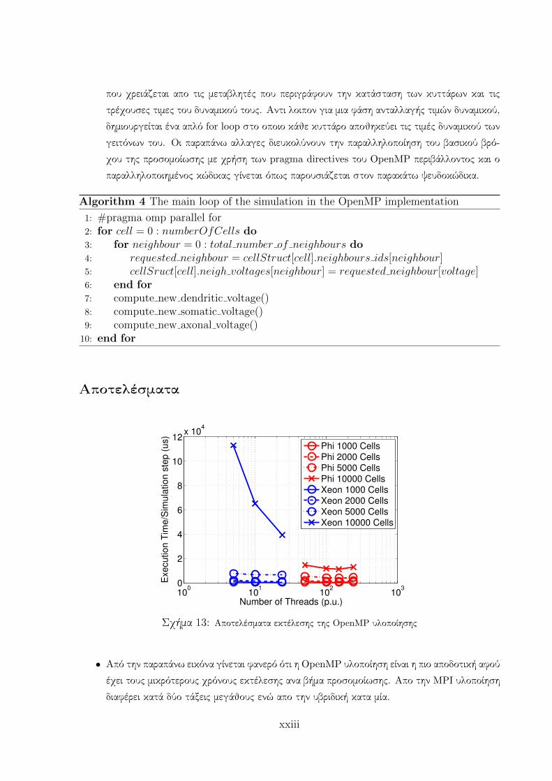
Σχήμα 13: Αποτελέσματα εκτέλεσης της OpenMP υλοποίησης
• Από την παραπάνω εικόνα γίνεται φανερό ότι η OpenMP υλοποίηση είναι η πιο αποδοτική αφού
έχει τους μικρότερους χρόνους εκτέλεσης ανα βήμα προσομοίωσης. Απο την MPI υλοποίηση
διαφέρει κατά δύο τάξεις μεγάθους ενώ απο την υβριδική κατα μία.
xxiii

• Η υλοποίηση είναι πιο αποδοτική όταν εκτελείται στον Xeon Phi επεξεργαστή παρά στον
Xeon αφού οι χρόνοι εκτέλεσης ανα βήμα προσομοίωσης είναι μειωμένοι για όλα τα μεγέθη
δικτύων που εξετάστηκαν. Αυτό το αποτέλεσμα ήταν αναμενόμενο αφού η OpenMP υλο-
ποίηση αξιοποιεί την παραλληλία της εφαρμογής η οποία και αποδίδει καλύτερα στο μαζικά
παράλληλο περιβάλλον του Xeon Phi. Η εφαρμογή κλιμακώνει αποδοτικά μέχρι και για 150
νήματα.
• Παρατηρείται ότι η εφαρμογή φαίνειται να είναι πιο αποδοτική στον Xeon Phi σε σχέση με
τον Xeon όσο το μεγέθος του δικτύου αυξάνει. Αυτή η παρατήρηση είναι πολύ σημαντική
αν λάβουμε υπ όψιν ότι οι προσομοιώσεις των κυττάρων του εγκεφάλου στοχεύουν στην
προσομοίωση οσο το δυνατόν μεγαλύτερων δικτύων νευρώνων. Προς αυτή την κατεύθυνση,
η χρήση του Xeon Phi φαίνεται πολλά υποσχόμενη.
xxiv
Acknowledgements
The current thesis is the result of my work in collaboration with the Microprocessors and
Digital Systems Laboratory (MicroLab) of NTUA on the Xeon Phi architecture for over a period
of six months (March 2015 - October 2015). I would like to thank my supervisor, Prof. Dimitrios
Soudris for his guidance, encouragement and inspiration as well as the opportunity to work with
the pioneering Xeon Phi architecture. Special thanks goes to Mr. George Chatzikonstantis,
whose invaluable help with the problems of the platform and the application’s parallelisation
contributed drastically to the completion of this work and to Mr. Dimitrios Rodopoulos for his
priceless contribution. Credits are due to the Hartree Centre for allowing us to use their Xeon
Phi cluster and for willingly helping us whenever a problem occurred.
I would like to thank my friends and fellow students who have been the best company I
could ever have during my studies, and especially Christos Michas and Konstantina Koliogeorgi.
Wholehearted thanks goes to my family, my parents and my sisters for their priceless support
during not only the last five years’ but throughout my life’s challenges.
xxv
Chapter 1
Introduction
Many large-scale projects nowadays focus on the exploration of the brain’s unfathomable and
complex functions [2]. Such research can be very beneficial for the understanding of a variety of
mental illnesses. For instance, great effort has been put on the development of implantable chips
that help patients cope with serious diseases such as epilepsy and Parkinson’s disease [53]. To
that direction, brain cell simulations have been proven to be a very useful tool in the hands of
neuroscientists. They provide them with the capability to study and predict the brain activity
and thus, develop the proper devices and mechanisms to assist the improvement of patients
living conditions.
The function of the human brain’s cerebellum still remains mostly obscure for neuroscientists.
Research has proved an association between the cerebellum and cognitive and language skills as
well as motor manipulation [16]. The Inferior Olivary Nucleus is a part of human brain’s olivary
body which provides major input to the cerebellum and is involved in human space perception
and motor skills. Significant research has been conducted to specify the function of this brain
area and important conclusions have been extracted [10].
The Inferior Olive (IO) simulator used in this work is a compartmental model of the IO
neuron, based on the time-driven plausible equations of the Hodgkin-Huxley electrical model of
the neural cell [1]. The cells are considered to be divided in three compartments with different
functionalities, the dendrites, the soma and the axon. The simulation stores the voltage of the
cells’ membrane in every simulation step tracking the exchanging of voltage levels and the input
of stimuli to the cells. The simulator aims at simulating a user-defined network. The user,
the neuroscientist, provides the application with the dimensions of the three-dimensional solid
rectangular topology they wish to simulate and the code generates a file specifying the connec-
tivity scheme between the neurons. Thus, the application simulates three-dimensional pieces of
brain matter for as long as the neuroscientist determines. The simulation is very demanding in
terms of computational resources due to the size of the cell network simulated and the neuron
interconnectivity degree. In the light of this observation, the need for parallel execution of the
1
simulation is essential and great effort has been put to the parallel implementation of the ap-
plication. The simulator has already been ported to various multicore platforms, such as the
Single-chip Cloud Computer (SCC) [47].
This thesis covers the porting of the simulator to a Many Integrated Core Architecture
(MIC) machine. The choice to port the simulator on the MIC architecture was motivated by
the technical features of the architecture that include support of effective hyper-threading and
a variety of available programming paradigms. The Xeon Phi Coprocessor [33] is utilised in
order to explore the parallelism of the IO simulator’s application and achieve the maximum
parallelisation possible by taking advantage of the resources of the coprocessor.
Effort has been made to use as many of the programming models the platform offers as pos-
sible in order to compare our application’s efficiency and scaling capabilities. To that direction,
a previously developed Message Passing Interface (MPI) implementation of the simulator [47]
has been used as the baseline for the creation of an OpenMP implementation. After testing and
running several configurations for both the MPI and OpenMP implementations on the Xeon and
the Xeon Phi, some configurations emerged as the best for each programming model in the as-
pect of performance. The OpenMP and MPI programming models were therefore combined into
a Hybrid MPI/OpenMP implementation aiming to take advantage of the best configurations for
each model individually. As a result a better performance of the application was expected.
In Chapter 2, a brief overview of neuron modelling and the types of models currently used is
presented as well as short history of Many-Core platforms. Their programming paradigms are
elaborated to inform the reader about the variety of programming models for parallel architec-
tures. In Chapter 3, the thesis holds an overview of the Inferior Olivary Nucleus cells and the
simulator used. Information about the data flow of the simulation and the contribution of the
current thesis to the simulator is introduced. The Many Integrated Core (MIC) architecture is
also presented. Basic information about the hardware and software elements of the architecture
is provided along with the programming paradigm of the platform and the author’s experiences.
In Chapter 5 the procedure followed to develop the OpenMP implementation is introduced.
The optimisations developed in order to create a more massively parallel implementation and
thus, take better advantage of the Xeon Phi’s capacities are presented. The efficiency and
scalability measurements on both the Xeon processor and the Xeon Phi coprocessor are pro-
vided. In Chapter 4 the MPI implementation of the simulator is demonstrated along with its
scalability and performance results on the Xeon processor and the Xeon Phi coprocessor. The
Hybrid MPI/OpenMP implementation is introduced as well, in conjunction with its scalability
results. A comparative study of the scalability and efficiency results of the programming models
is presented in Chapter 6. Important conclusions valuable to the reader are discussed, as well
as suggestions for improving the existing work in the future. The Chapter concludes with an
assertion from the author on how the Xeon Phi Coprocessor can be used for future developers
2

interested in maximising the efficiency of their highly-parallel applications.
3
Chapter 2
Prior Art
This chapter summarises the prior art in neuron modelling and offers a brief overview of the
Many-Core platforms and their programming paradigms. Neuron simulations have proven to
be very demanding applications in terms of efficiency, performance and computational resources
and thus it is very interesting to explore their possible implementations on Many-Core platforms
[20].
2.1 Neuron Modelling
The phenomena taking place in the human brain are very complex and related to various
underlying computations. As a result, it is essential that the developed neuron models are
capable of providing both experimental results and possible interpretations of these hidden
computations. To this direction, four levels of abstraction in brain organisation have been
developed. The first includes the typical scientific reduction which describes the observable brain
functions and explains them based on descriptions of the functions in lower levels of analysis. The
second constitutes a divide-and-conquer approach based on the synthesis of systems whereby,
each one execute a specific function in order to create a more complex system. The third level
is associated with computational modelling and has a computational, an algorithmic and an
implementational level. Finally, the fourth is based on the idea of the ”levels of processing” that
set an analytical hierarchy among the several brain parts that cooperate during the process of
a stimulus [7].
There are two main categories of neuron models [7]:
• Conventional reductive models
These models are based on the first organisation level, the scientific reduction, and their
main purposes are to describe the neural phenomena and provide explanations build on
4
the biological mechanisms that might be responsible for them. The quantification of
these models, although not mandatory, is recommended concerning the need to check the
accuracy of the model in describing the phenomena. The different levels of abstraction
lead to different levels of modelling. The descriptive models demonstrate the behaviour
without taking into consideration the processes in the substrate, whereas the explanatory
models capture the phenomena by reducing them to lower level models.
• Computational interpretive models
This point of view considers the tasks of the brain as computational procedures that
interpret the overall behaviour of the neural components of the system, for the completion
of this task. The basic computations are conducted through representation, storage and
transformations of the stimuli gathered from the outside world by the neural system to a
form that is useful for the satisfaction of the task under examination. The computational
models are often used synthetically in practice. More specifically, networks of neurons
are constructed to perform a computational task. The neurons are described to some
level of abstraction, and the network’s behaviour is compared with the one observed in
physiological experiments in order to examine the correctness of the model [22, 25].
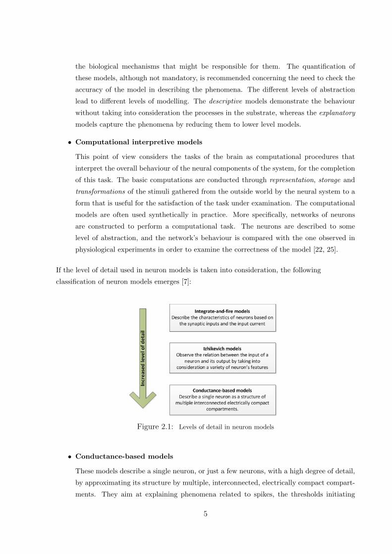
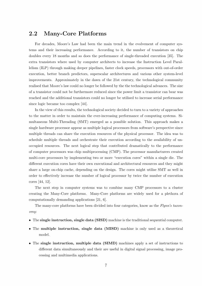
If the level of detail used in neuron models is taken into consideration, the following
classification of neuron models emerges [7]:
Figure 2.1: Levels of detail in neuron models
• Conductance-based models
These models describe a single neuron, or just a few neurons, with a high degree of detail,
by approximating its structure by multiple, interconnected, electrically compact compart-
ments. They aim at explaining phenomena related to spikes, the thresholds initiating
5
them, active channels and like. Some problems with these models are the lack of accurate
experimental data on the locations of the dendrites and the large number of parameters
they include. The former limits the capability of testing the accuracy of the model and
the latter makes the behaviour of the model unpredictable and depending on the exact
values of the parameters. A project recently conducted to tackle the lack of accurate
experimental data on the locations of neurons is “The NeuroProbes Project”. In this
work, multifunctional probe arrays for neural recording and stimulation are created and
offer the possibility to separately define the position of each probe with respect to single
neurons [14, 19]. An extension of the conductance-based models are the compartmental
models.
• Integrate-and-fire models
Integrate-and-fire models are good for simulating large networks of neurons [7]. They
describe the membrane potential of a neuron based on the synaptic inputs and the input
current it receives. An action potential is generated when the membrane potential exceeds
a threshold value, but the model does not take into account the actual changes associated
with the membrane voltage and the conductances causing the action potential in contrast
to the conductance-based models. The synaptic inputs to the neuron by other neurons
of the network are considered to be stochastic processes and are described as temporally
homogeneous Poisson processes [3].
• Firing-rate models or Izhikevich models
These models observe the relation between the input and the output of neuron networks as
if the neurons themselves were black boxes [7].They combine the efficiency of an integrate-
and-fire model with the transparency of the Hodgkin-Huxley model. However, the actual
equations of the Hodgkin-Huxley model [1] can not be used since they are very computa-
tionally demanding. In their place, a simple spiking model is utilised that is as biologically
plausible as the Hodgkin-Huxley model but much more computationally efficient [9].
The IO Model used in this thesis is based on the Hodgkin-Huxley [1] time driven-differential
equations. It falls under the category of compartmental models, an extension of the
conductance based models. The model will be analysed further in Chapter 3.
6
2.2 Many-Core Platforms
For decades, Moore’s Law had been the main trend in the evolvement of computer sys-
tems and their increasing performance. According to it, the number of transistors on chip
doubles every 18 months and so does the performance of single-threaded execution [35]. The
extra transistors where used by computer architects to increase the Instruction Level Paral-
lelism (ILP) through making deeper pipelines, faster clock speeds, processors with out-of-order
execution, better branch predictors, superscalar architectures and various other system-level
improvements. Approximately in the dawn of the 21st century, the technological community
realised that Moore’s law could no longer be followed by the the technological advances. The size
of a transistor could not be furthermore reduced since the power limit a transistor can bear was
reached and the additional transistors could no longer be utilised to increase serial performance
since logic became too complex [44].
In the view of this results, the technological society decided to turn to a variety of approaches
to the matter in order to maintain the ever-increasing performance of computing systems. Si-
multaneous Multi-Threading (SMT) emerged as a possible solution. This approach makes a
single hardware processor appear as multiple logical processors from software’s perspective since
multiple threads can share the execution resources of the physical processor. The idea was to
schedule multiple threads and orchestrate their execution according to the availability of un-
occupied resources. The next logical step that contributed dramatically to the performance
of computer processors was chip multiprocessing (CMP). The processor manufacturers created
multi-core processors by implementing two or more “execution cores” within a single die. The
different execution cores have their own executional and architectural resources and they might
share a large on-chip cache, depending on the design. The cores might utilise SMT as well in
order to effectively increase the number of logical processor by twice the number of execution
cores [44, 12].
The next step in computer systems was to combine many CMP processors to a cluster
creating the Many-Core platforms. Many-Core platforms are widely used for a plethora of
computationally demanding applications [21, 6].
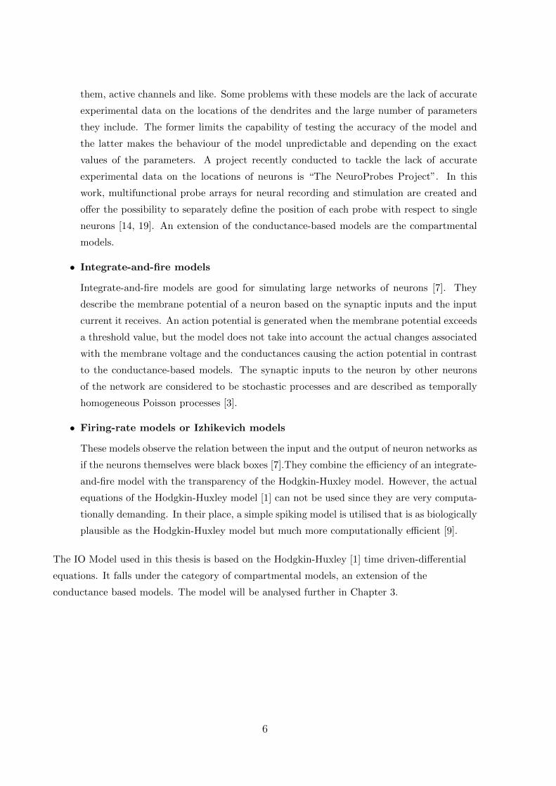
The many-core platforms have been divided into four categories, know as the Flynn’s taxon-
omy :
• The single instruction, single data (SISD) machine is the traditional sequential computer.
• The multiple instruction, single data (MISD) machine is only used as a theoretical
model.
• The single instruction, multiple data (SIMD) machines apply a set of instructions to
different data simultaneously and their are useful in digital signal processing, image pro-
cessing and multimedia applications.
7
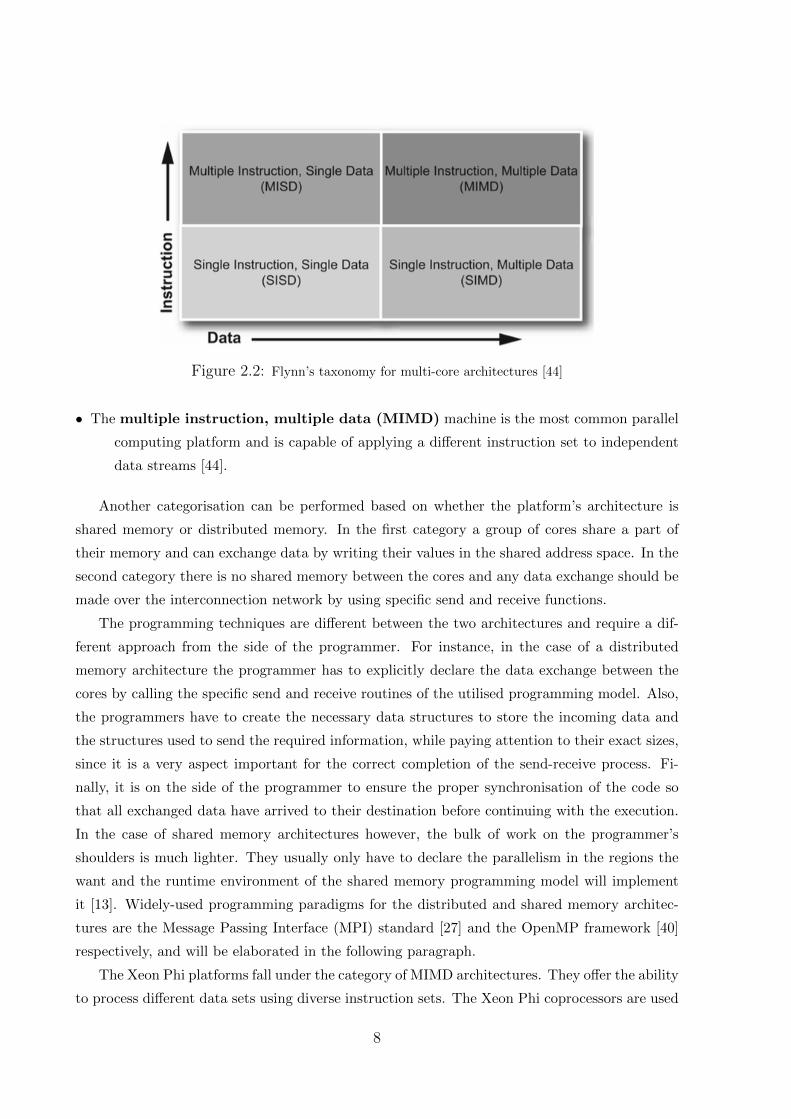
Figure 2.2: Flynn’s taxonomy for multi-core architectures [44]
• The multiple instruction, multiple data (MIMD) machine is the most common parallel
computing platform and is capable of applying a different instruction set to independent
data streams [44].
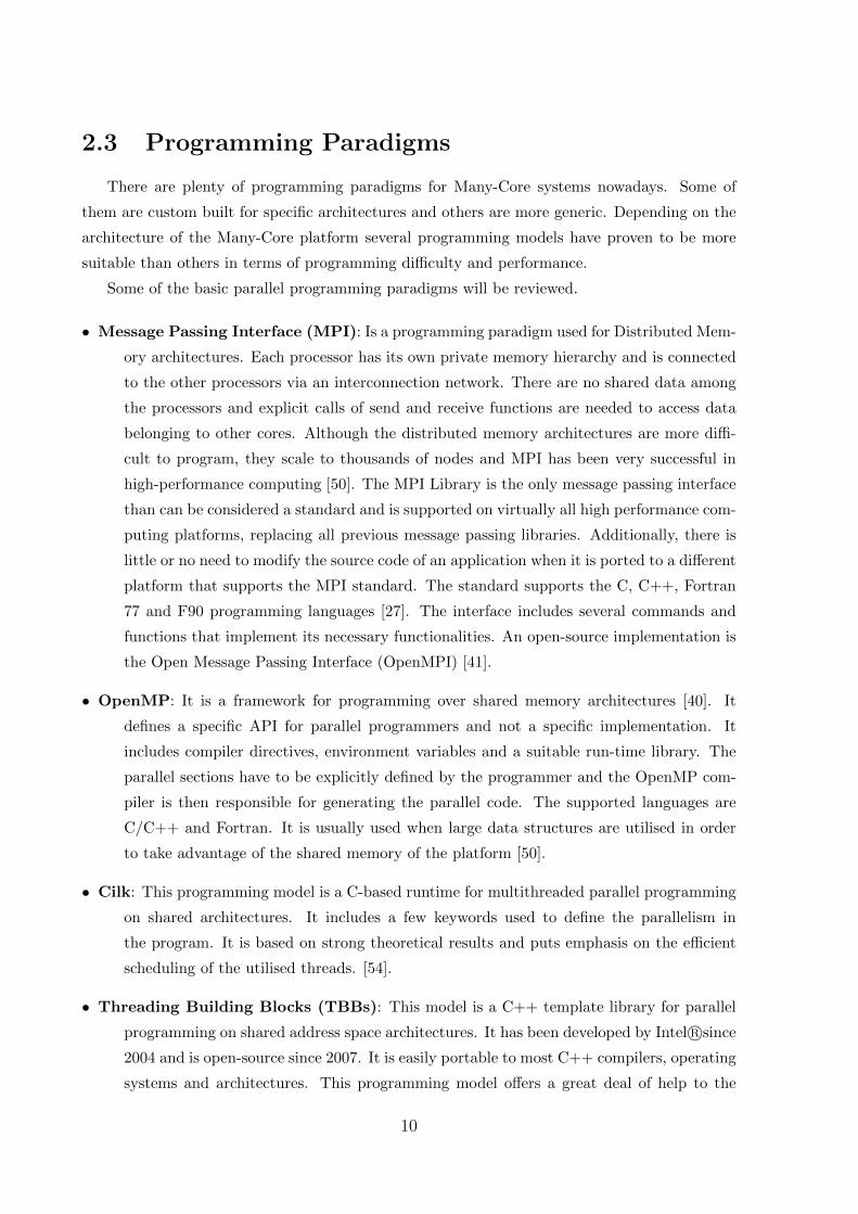
Another categorisation can be performed based on whether the platform’s architecture is
shared memory or distributed memory. In the first category a group of cores share a part of
their memory and can exchange data by writing their values in the shared address space. In the
second category there is no shared memory between the cores and any data exchange should be
made over the interconnection network by using specific send and receive functions.
The programming techniques are different between the two architectures and require a dif-
ferent approach from the side of the programmer. For instance, in the case of a distributed
memory architecture the programmer has to explicitly declare the data exchange between the
cores by calling the specific send and receive routines of the utilised programming model. Also,
the programmers have to create the necessary data structures to store the incoming data and
the structures used to send the required information, while paying attention to their exact sizes,
since it is a very aspect important for the correct completion of the send-receive process. Fi-
nally, it is on the side of the programmer to ensure the proper synchronisation of the code so
that all exchanged data have arrived to their destination before continuing with the execution.
In the case of shared memory architectures however, the bulk of work on the programmer’s
shoulders is much lighter. They usually only have to declare the parallelism in the regions the
want and the runtime environment of the shared memory programming model will implement
it [13]. Widely-used programming paradigms for the distributed and shared memory architec-
tures are the Message Passing Interface (MPI) standard [27] and the OpenMP framework [40]
respectively, and will be elaborated in the following paragraph.
The Xeon Phi platforms fall under the category of MIMD architectures. They offer the ability
to process different data sets using diverse instruction sets. The Xeon Phi coprocessors are used
8
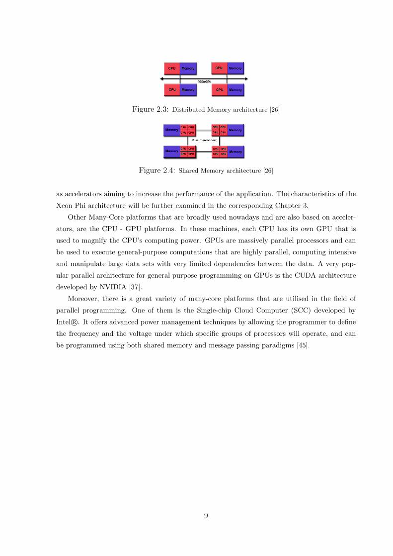
Figure 2.3: Distributed Memory architecture [26]
Figure 2.4: Shared Memory architecture [26]
as accelerators aiming to increase the performance of the application. The characteristics of the
Xeon Phi architecture will be further examined in the corresponding Chapter 3.
Other Many-Core platforms that are broadly used nowadays and are also based on acceler-
ators, are the CPU - GPU platforms. In these machines, each CPU has its own GPU that is
used to magnify the CPU’s computing power. GPUs are massively parallel processors and can
be used to execute general-purpose computations that are highly parallel, computing intensive
and manipulate large data sets with very limited dependencies between the data. A very pop-
ular parallel architecture for general-purpose programming on GPUs is the CUDA architecture
developed by NVIDIA [37].
Moreover, there is a great variety of many-core platforms that are utilised in the field of
parallel programming. One of them is the Single-chip Cloud Computer (SCC) developed by
Intel R©. It offers advanced power management techniques by allowing the programmer to define
the frequency and the voltage under which specific groups of processors will operate, and can
be programmed using both shared memory and message passing paradigms [45].
9
2.3 Programming Paradigms
There are plenty of programming paradigms for Many-Core systems nowadays. Some of
them are custom built for specific architectures and others are more generic. Depending on the
architecture of the Many-Core platform several programming models have proven to be more
suitable than others in terms of programming difficulty and performance.
Some of the basic parallel programming paradigms will be reviewed.
• Message Passing Interface (MPI): Is a programming paradigm used for Distributed Mem-
ory architectures. Each processor has its own private memory hierarchy and is connected
to the other processors via an interconnection network. There are no shared data among
the processors and explicit calls of send and receive functions are needed to access data
belonging to other cores. Although the distributed memory architectures are more diffi-
cult to program, they scale to thousands of nodes and MPI has been very successful in
high-performance computing [50]. The MPI Library is the only message passing interface
than can be considered a standard and is supported on virtually all high performance com-
puting platforms, replacing all previous message passing libraries. Additionally, there is
little or no need to modify the source code of an application when it is ported to a different
platform that supports the MPI standard. The standard supports the C, C++, Fortran
77 and F90 programming languages [27]. The interface includes several commands and
functions that implement its necessary functionalities. An open-source implementation is
the Open Message Passing Interface (OpenMPI) [41].
• OpenMP: It is a framework for programming over shared memory architectures [40]. It
defines a specific API for parallel programmers and not a specific implementation. It
includes compiler directives, environment variables and a suitable run-time library. The
parallel sections have to be explicitly defined by the programmer and the OpenMP com-
piler is then responsible for generating the parallel code. The supported languages are
C/C++ and Fortran. It is usually used when large data structures are utilised in order
to take advantage of the shared memory of the platform [50].
• Cilk: This programming model is a C-based runtime for multithreaded parallel programming
on shared architectures. It includes a few keywords used to define the parallelism in
the program. It is based on strong theoretical results and puts emphasis on the efficient
scheduling of the utilised threads. [54].
• Threading Building Blocks (TBBs): This model is a C++ template library for parallel
programming on shared address space architectures. It has been developed by Intel R©since
2004 and is open-source since 2007. It is easily portable to most C++ compilers, operating
systems and architectures. This programming model offers a great deal of help to the
10
developers since there is a variety of templates ready to use and the programmer only
declares the parallelism while the library implements it. The model is designed to offer
scalability by utilising a load balancing mechanism among the tasks used [31].
• Unified Parallel C (UPC): Is an ANSI C extension for single-program multiple-data par-
allel programming in both shared and distributed memory platforms. It is based on the
philosophy of the C language as it has the same syntax and the same semantics. This
aspect might be useful for the programmers who are familiar with the C programming
environment [8].
• Charm++: Is a platform-independent object-oriented programming model supporting the
C/C++ and Fortran programming languages. It is based on the creation of collections of
objects which communicate with each other. The communication is implemented through
invoking methods on remote objects in an object collection. The programmer does not
have to deal with explicit management of cores and threads since the adaptive runtime
system is responsible for organising the execution [5].
• CUDA C: This programming model is a software environment that allows developers to use
the C programming language to program the CUDA general purpose parallel computing
platform, developed by NVIDIA [39]. The programmer has to define the parts of the
code to be executed on GPU and on CPU using function qualifiers. The programming
model has some restrictions about the functions running on the device and the fact that
the programmer has to explicitly declare the data transportations between the devices
increases the level of development difficulty [38].
• OpenCL: Is a low-level API designed for heterogeneous computing and runs on CUDA-
powered GPUs. In contrast with CUDA C, it is an open source standard for cross-
platform parallel programming. It supports C and C++ and is intended to be used for
supercomputers, embedded systems and mobile devices [15]. A disadvantage emerging
when using this programming model is that the programmer might need to modify the
application to achieve high performance for a new processor [50].
In this thesis the MPI and the OpenMP programming models are used. The primal purpose
of this choice is comparing a shared memory programming model with a distributed memory
one to observe the application’s behaviour and also the global recognition and meticulous de-
velopment of these paradigms. MPI and OpenMP both offer the ability to test different aspects
of the application’s behaviour and performance and the author was already familiar with their
use. Moreover, the Intel OpenMP library and the Intel MPI Library were already installed on
the Intel Xeon Phi platforms utilised.
11
Chapter 3
Implementation Specifications
3.1 The Inferior Olivary Nucleus
The Inferior Olivary Nucleus cells are a very important group of brain cells and have been
associated with brain functions such as the learning procedure and the synchronisation of move-
ments [10]. The cells are stimulated by the human senses and pass on input to the cerebellar
cortex via the Purkinje cells. In the case that the IO cells suffer any damage, the patient becomes
unable to synchronize their movements. As a result, severe cases of ataxia can be demonstrated
[11] and thus, the great importance of the IO cells motivated the development of a simulator.
The simulator used in this work is a biologically accurate neural cell simulator, based on the
differential equations of the time-driven Hodgkin-Huxley models [1].
The application aims at simulating a user-defined network of IO cells. The user provides the
size of the network along with a custom input current at each simulation step and a connectivity
scheme. The biological parameters of the entire network are calculated and recorded such as the
voltage levels of each cell as it reacts to the stimuli (input current) as well as other parameters
that define its state. Thus, the application is biologically accurate and transparent which makes
it a lot different from most black-box approaches so far(e.g. neural networks [42]).
The IO cell in this simulation is modelled using a compartmental model. This model falls
under the category of Conductance-based models that were elaborated on Chapter 2. In this
model, each cell comprises of 3 compartments: the dendrite, the soma and the axon. Each
compartment serves a different biological purpose and has different membrane voltage levels.
• The dendrite compartment is responsible for the cell’s communication with the other cells
on the grid. The communication is simulated by saving the dendritic membrane voltage
values of the other cells. These values and other biological parameters, determine the
computations that calculate the dendrite’s potential in each simulation step. Moreover,
the dendrite receives stimuli from the environment as input current. It has been proven
12
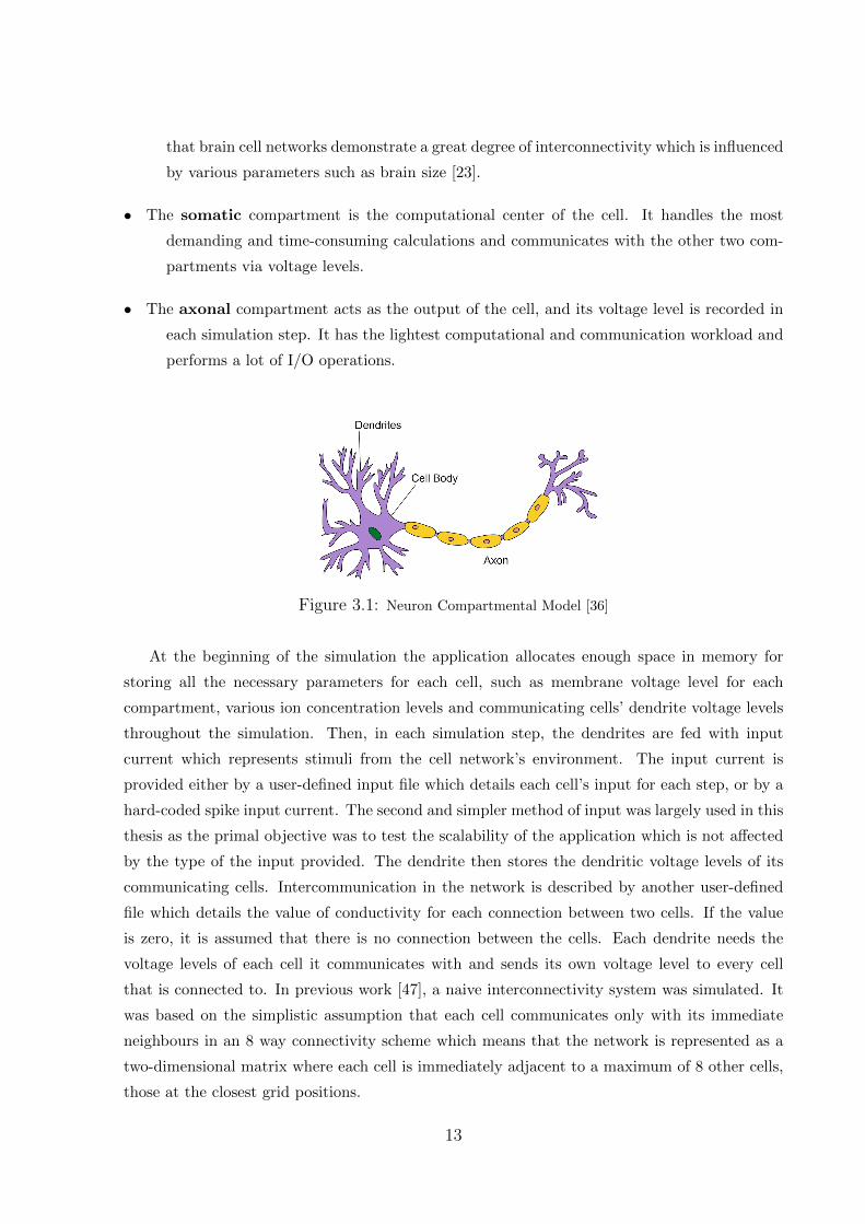
that brain cell networks demonstrate a great degree of interconnectivity which is influenced
by various parameters such as brain size [23].
• The somatic compartment is the computational center of the cell. It handles the most
demanding and time-consuming calculations and communicates with the other two com-
partments via voltage levels.
• The axonal compartment acts as the output of the cell, and its voltage level is recorded in
each simulation step. It has the lightest computational and communication workload and
performs a lot of I/O operations.
Figure 3.1: Neuron Compartmental Model [36]
At the beginning of the simulation the application allocates enough space in memory for
storing all the necessary parameters for each cell, such as membrane voltage level for each
compartment, various ion concentration levels and communicating cells’ dendrite voltage levels
throughout the simulation. Then, in each simulation step, the dendrites are fed with input
current which represents stimuli from the cell network’s environment. The input current is
provided either by a user-defined input file which details each cell’s input for each step, or by a
hard-coded spike input current. The second and simpler method of input was largely used in this
thesis as the primal objective was to test the scalability of the application which is not affected
by the type of the input provided. The dendrite then stores the dendritic voltage levels of its
communicating cells. Intercommunication in the network is described by another user-defined
file which details the value of conductivity for each connection between two cells. If the value
is zero, it is assumed that there is no connection between the cells. Each dendrite needs the
voltage levels of each cell it communicates with and sends its own voltage level to every cell
that is connected to. In previous work [47], a naive interconnectivity system was simulated. It
was based on the simplistic assumption that each cell communicates only with its immediate
neighbours in an 8 way connectivity scheme which means that the network is represented as a
two-dimensional matrix where each cell is immediately adjacent to a maximum of 8 other cells,
those at the closest grid positions.
13
...
...
...
Dendrite
Soma
Axon
Dendrite
Soma
Axon
Dendrite
Soma
Axon
Dendrite
Soma
Axon
Dendrite
Soma
Axon
Dendrite
Soma
Axon
Input
N ei ghboring
Cells
N ei ghboring
Cells
Input Input
t0 t1 t2 ...
...
...
...
...
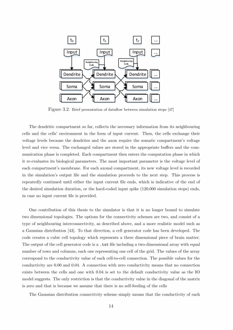
Figure 3.2: Brief presentation of dataflow between simulation steps [47]
The dendritic compartment so far, collects the necessary information from its neighbouring
cells and the cells’ environment in the form of input current. Then, the cells exchange their
voltage levels because the dendrites and the axon require the somatic compartment’s voltage
level and vice versa. The exchanged values are stored in the appropriate buffers and the com-
munication phase is completed. Each compartment then enters the computation phase in which
it re-evaluates its biological parameters. The most important parameter is the voltage level of
each compartment’s membrane. For each axonal compartment, its new voltage level is recorded
in the simulation’s output file and the simulation proceeds to the next step. This process is
repeatedly continued until either the input current file ends, which is indicative of the end of
the desired simulation duration, or the hard-coded input spike (120,000 simulation steps) ends,
in case no input current file is provided.
One contribution of this thesis to the simulator is that it is no longer bound to simulate
two dimensional topologies. The options for the connectivity schemes are two, and consist of a
type of neighbouring interconnectivity, as described above, and a more realistic model such as
a Gaussian distribution [43]. To that direction, a cell generator code has been developed. The
code creates a cubic cell topology which represents a three dimensional piece of brain matter.
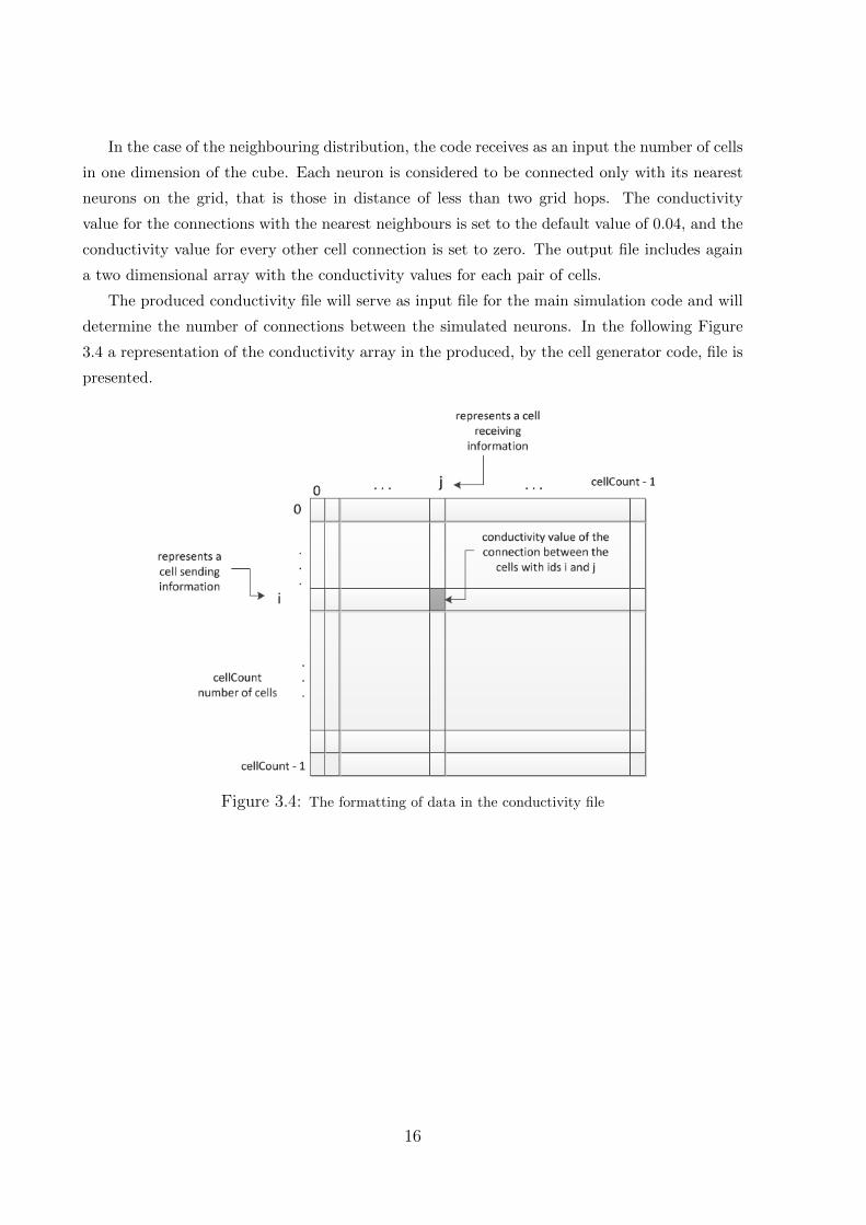
The output of the cell generator code is a .txt file including a two-dimensional array with equal
number of rows and columns, each one representing one cell of the grid. The values of the array
correspond to the conductivity value of each cell-to-cell connection. The possible values for the
conductivity are 0.00 and 0.04. A connection with zero conductivity means that no connection
exists between the cells and one with 0.04 is set to the default conductivity value as the IO
model suggests. The only restriction is that the conductivity value in the diagonal of the matrix
is zero and that is because we assume that there is no self-feeding of the cells
The Gaussian distribution connectivity scheme simply means that the conductivity of each
14
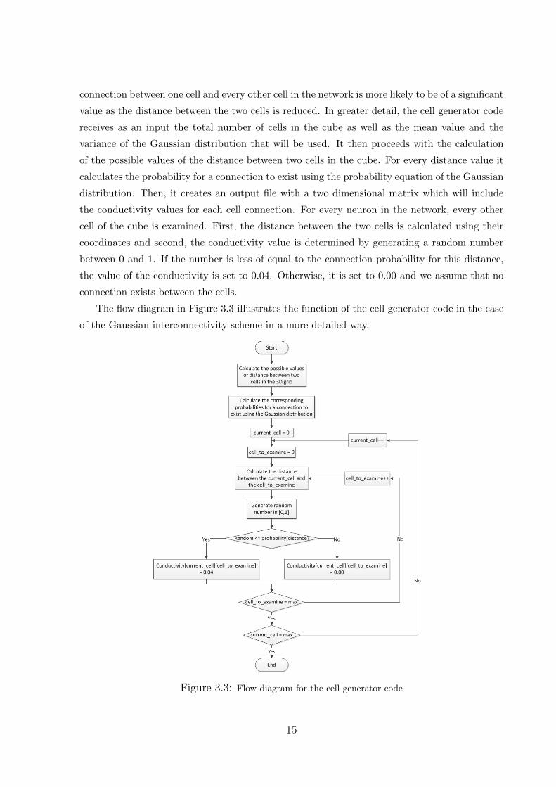
connection between one cell and every other cell in the network is more likely to be of a significant
value as the distance between the two cells is reduced. In greater detail, the cell generator code
receives as an input the total number of cells in the cube as well as the mean value and the
variance of the Gaussian distribution that will be used. It then proceeds with the calculation
of the possible values of the distance between two cells in the cube. For every distance value it
calculates the probability for a connection to exist using the probability equation of the Gaussian
distribution. Then, it creates an output file with a two dimensional matrix which will include
the conductivity values for each cell connection. For every neuron in the network, every other
cell of the cube is examined. First, the distance between the two cells is calculated using their
coordinates and second, the conductivity value is determined by generating a random number
between 0 and 1. If the number is less of equal to the connection probability for this distance,
the value of the conductivity is set to 0.04. Otherwise, it is set to 0.00 and we assume that no
connection exists between the cells.
The flow diagram in Figure 3.3 illustrates the function of the cell generator code in the case
of the Gaussian interconnectivity scheme in a more detailed way.
Figure 3.3: Flow diagram for the cell generator code
15
In the case of the neighbouring distribution, the code receives as an input the number of cells
in one dimension of the cube. Each neuron is considered to be connected only with its nearest
neurons on the grid, that is those in distance of less than two grid hops. The conductivity
value for the connections with the nearest neighbours is set to the default value of 0.04, and the
conductivity value for every other cell connection is set to zero. The output file includes again
a two dimensional array with the conductivity values for each pair of cells.
The produced conductivity file will serve as input file for the main simulation code and will
determine the number of connections between the simulated neurons. In the following Figure
3.4 a representation of the conductivity array in the produced, by the cell generator code, file is
presented.
Figure 3.4: The formatting of data in the conductivity file
16
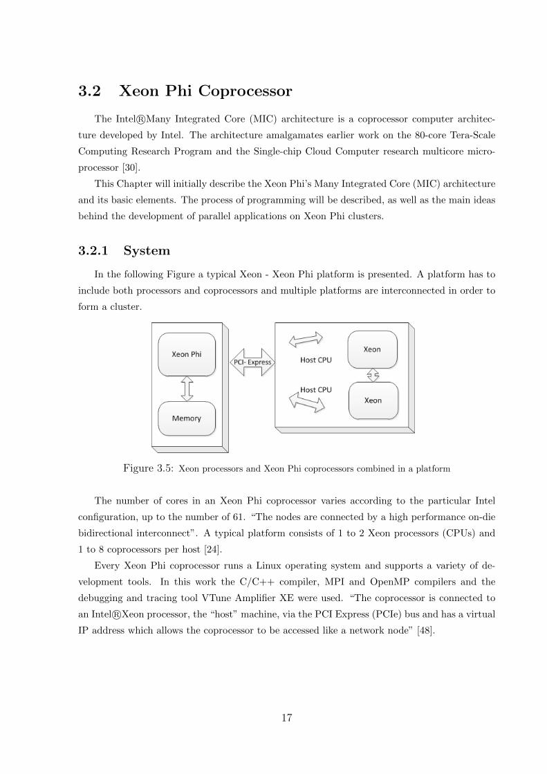
3.2 Xeon Phi Coprocessor
The Intel R©Many Integrated Core (MIC) architecture is a coprocessor computer architec-
ture developed by Intel. The architecture amalgamates earlier work on the 80-core Tera-Scale
Computing Research Program and the Single-chip Cloud Computer research multicore micro-
processor [30].
This Chapter will initially describe the Xeon Phi’s Many Integrated Core (MIC) architecture
and its basic elements. The process of programming will be described, as well as the main ideas
behind the development of parallel applications on Xeon Phi clusters.
3.2.1 System
In the following Figure a typical Xeon - Xeon Phi platform is presented. A platform has to
include both processors and coprocessors and multiple platforms are interconnected in order to
form a cluster.
Figure 3.5: Xeon processors and Xeon Phi coprocessors combined in a platform
The number of cores in an Xeon Phi coprocessor varies according to the particular Intel
configuration, up to the number of 61. “The nodes are connected by a high performance on-die
bidirectional interconnect”. A typical platform consists of 1 to 2 Xeon processors (CPUs) and
1 to 8 coprocessors per host [24].
Every Xeon Phi coprocessor runs a Linux operating system and supports a variety of de-
velopment tools. In this work the C/C++ compiler, MPI and OpenMP compilers and the
debugging and tracing tool VTune Amplifier XE were used. “The coprocessor is connected to
an Intel R©Xeon processor, the “host” machine, via the PCI Express (PCIe) bus and has a virtual
IP address which allows the coprocessor to be accessed like a network node” [48].
17
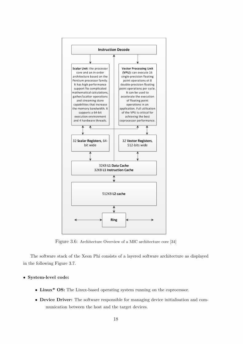
Figure 3.6: Architecture Overview of a MIC architecture core [34]
The software stack of the Xeon Phi consists of a layered software architecture as displayed
in the following Figure 3.7.
• System-level code:
• Linux* OS: The Linux-based operating system running on the coprocessor.
• Device Driver: The software responsible for managing device initialisation and com-
munication between the host and the target devices.
18
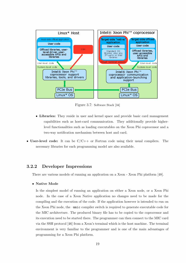
Figure 3.7: Software Stack [34]
• Libraries: They reside in user and kernel space and provide basic card management
capabilities such as host-card communication. They additionally provide higher-
level functionalities such as loading executables on the Xeon Phi coprocessor and a
two-way notification mechanism between host and card.
• User-level code: It can be C/C++ or Fortran code using their usual compilers. The
necessary libraries for each programming model are also available.
3.2.2 Developer Impressions
There are various models of running an application on a Xeon - Xeon Phi platform [48].
• Native Mode
Is the simplest model of running an application on either a Xeon node, or a Xeon Phi
node. In the case of a Xeon Native application no changes need to be made for the
compiling and the execution of the code. If the application however is intended to run on
the Xeon Phi node, the –mmic compiler switch is required to generate executable code for
the MIC architecture. The produced binary file has to be copied to the coprocessor and
its execution need to be started there. The programmer can then connect to the MIC card
via the SSH protocol [46] from a Xeon’s terminal which is the host machine. The terminal
environment is very familiar to the programmer and is one of the main advantages of
programming for a Xeon Phi platform.
19
• Offload Mode
In this model, regions of C/C++ or Fortran code can be offloaded to the Xeon Phi
coprocessor and be run there. The desired regions are stated using OpenMP-like pragmas
that tell the compiler to generate code for both the Xeon processor and the Xeon Phi
coprocessor. The compiler also generates the code to transfer automatically the data to
the coprocessor although the programmer can interfere to this process by adding data
clauses to the offload pragma. No specific compiler flag is required in this model since the
offload is enabled by default. This model uses the Xeon Phi coprocessor like an accelerator.
• Symmetric Mode
This model refers only to an MPI or a Hybrid MPI/OpenMP application. In this model,
MPI ranks reside both on the Xeon processor and the Xeon Phi coprocessor. The program-
mer should take into account the data transfer overhead over the PCIe so it is preferable to
minimise the communication between the CPU and the coprocessor. It is also important
to keep in mind that the coprocessor has a limited amount of memory, a fact that favors
the shared memory approach. So it might be more efficient to spawn more threads on the
coprocessor than placing many MPI ranks.
In this thesis the Native Mode is explored by executing an OpenMP, an MPI and a Hybrid
MPI/OpenMP implementation, on the Xeon processor and the Xeon Phi coprocessor natively.
There is a great variety of sources which provide the developers with helpful information
about Xeon Phi programming. The Intel R©Corporation has developed a forum [29] specifically
for the Many Integrated Core architecture where very useful information can be found about a
plethora of issues concerning the architecture and its programming. There are also some very
useful development tutorials to guide the new programmer through the basic programming ideas
[34].
20
3.3 Target platforms
To develop and test the simulator’s implementations in this thesis the Blue Wonder Phi
Cluster of the Hartree Centre [17] and a single-node Xeon-Xeon Phi arrangement were utilised.
A typical Xeon - Xeon Phi node in the Blue Wonder Cluster consists of 24 Xeon CPU E5-
2697 v2, 2.70GHz processors [52] with the capability to support 1 threads per processor and
61 cores in the Xeon Phi coprocessor, with a multithreading degree of 4 threads per core. The
Xeon processor node on the single-node Xeon-Xeon Phi arrangement has 4 Xeon CPU E5-2609
v2, 2.50GHz processors [51] and 57 cores in the Xeon Phi coprocessor with a total number of
228 threads to utilise for the native parallel simulations. The Intel Xeon processors of the Blue
Wonder cluster are of a newer generation and have more storage and performance capabilities.
The Blue Wonder Phi Cluster was used for the development of all the application’s imple-
mentations. It was properly equipped with all the necessary MPI and OpenMP libraries and
compilers. The single-node machine was utilised mainly for the OpenMP implementation since
the Intel MPI Library could not be available.
The two machines utilised offer very similar working environments, a fact that facilitates the
programmer’s effort to concurrently develop applications for both.
• When a programmer requests access to the Blue Wonder cluster via the ssh protocol, they
are connected to a Xeon hosting node. If they wish to use a Xeon Phi coprocessor they
have to request a Xeon Phi hosting node with the bsub -q phiq -Is bash command [4].
In order to develop an application on a Xeon-Phi node, the programmer has to load the
appropriate modules. The available modules can be seen by typing the module avail
command on the Xeon host terminal. For the compilation of either a MPI or an OpenMP
program for example, the intel mpi/5.0.3 mic compiler module has to be loaded to the
environment of the Xeon processor host. If the programmer wishes to be informed about
the list of modules currently loaded in the system, the module list command will print
the loaded modules in the terminal window.
The cluster offers various ways of running an application including direct execution on the
MIC card and dispatching jobs in the Phi queue. The user can write bash scripts to facili-
tate dispatching jobs to the Xeon Phi queue [18]. The results are printed in appropriately
defined output and error files and thus, the procedure of execution is simplified.
The single-node Xeon-Xeon Phi arrangement utilised, offers only direct execution for all
Xeon Phi applications.
• The user is connected via the ssh protocol to the Xeon node which is in direct communi-
cation with the Xeon Phi coprocessor. The only available way of running an application
on the MIC card is copying the executable file and all the necessary input files to the card
21

via the scp <executable/input file> mic0: command. The programmer then, has to
connect directly to the MIC card using the ssh mic0 command, set the appropriate envi-
ronmental variables, if needed, and run the application. A more detailed reference to the
specific OpenMP environment variables will be presented in the corresponding chapter,
Chapter 5.
22
Chapter 4
MPI-based Native Implementations
4.1 Development Details
4.1.1 The MPI implementation
The MPI implementation of the InfOli simulator is provided as legacy code to this thesis
[49]. It has been used as the baseline to develop the OpenMP and the Hybrid MPI/OpenMP
implementations. In the Hybrid MPI/OpenMP implementation a number of MPI ranks is
utilised and each rank spawns an equal number of OpenMP threads to run some previously
serial parts of the code in parallel regions, and thus increase the performance of the simulation.
In the following paragraph a brief description of the code’s function will be provided. The
MPI implementation receives as an input the total number of cells to simulate, the conductivity
file produced by the cell generator code, described in Chapter 3, and an optional input current
file including the stimuli provided to cells from the outside environment in every simulation step.
Then, an equal number of grid cells is assigned to each one of the available cores. It is therefore
important that the total number of cells is divided by the number of utilised cores. Each core
allocates the necessary memory space to store the parameters of its cells, like membrane voltages
and ion conductivities, and other structures needed for the simulation. A phase follows where
each core creates a list of nodes including information about all the other cores related to the
cells’ voltages that the current core needs to receive from the other utilised cores. At this point,
the conductivity file is read in order to define whether there is a connection between two cells
and subsequently between the cores that process them. In the following algorithm, the main
simulation loop is presented.
23
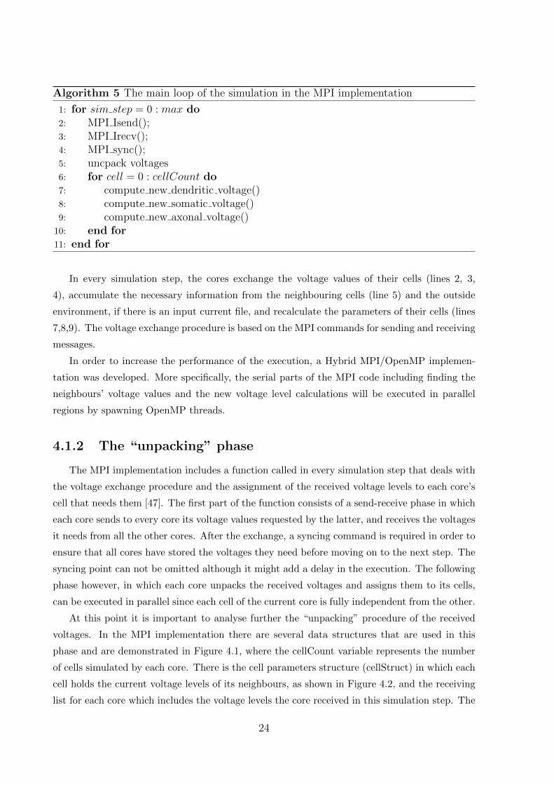
Algorithm 5 The main loop of the simulation in the MPI implementation
1: for sim step = 0 : max do2: MPI Isend();3: MPI Irecv();4: MPI sync();5: uncpack voltages6: for cell = 0 : cellCount do7: compute new dendritic voltage()8: compute new somatic voltage()9: compute new axonal voltage()
10: end for11: end for
In every simulation step, the cores exchange the voltage values of their cells (lines 2, 3,
4), accumulate the necessary information from the neighbouring cells (line 5) and the outside
environment, if there is an input current file, and recalculate the parameters of their cells (lines
7,8,9). The voltage exchange procedure is based on the MPI commands for sending and receiving
messages.
In order to increase the performance of the execution, a Hybrid MPI/OpenMP implemen-
tation was developed. More specifically, the serial parts of the MPI code including finding the
neighbours’ voltage values and the new voltage level calculations will be executed in parallel
regions by spawning OpenMP threads.
4.1.2 The “unpacking” phase
The MPI implementation includes a function called in every simulation step that deals with
the voltage exchange procedure and the assignment of the received voltage levels to each core’s
cell that needs them [47]. The first part of the function consists of a send-receive phase in which
each core sends to every core its voltage values requested by the latter, and receives the voltages
it needs from all the other cores. After the exchange, a syncing command is required in order to
ensure that all cores have stored the voltages they need before moving on to the next step. The
syncing point can not be omitted although it might add a delay in the execution. The following
phase however, in which each core unpacks the received voltages and assigns them to its cells,
can be executed in parallel since each cell of the current core is fully independent from the other.
At this point it is important to analyse further the “unpacking” procedure of the received
voltages. In the MPI implementation there are several data structures that are used in this
phase and are demonstrated in Figure 4.1, where the cellCount variable represents the number
of cells simulated by each core. There is the cell parameters structure (cellStruct) in which each
cell holds the current voltage levels of its neighbours, as shown in Figure 4.2, and the receiving
list for each core which includes the voltage levels the core received in this simulation step. The
24
unpacking phase examines each core’s cells and assigns them the received voltage levels from the
cells they neighbour with. This procedure if operated naively would have had a time complexity
of O(n3), where n is the number of cells in the grid. That is because, for each cell in a core, for
each cell voltage it needs, the node receiving list would have to be traversed in order to find the
corresponding voltage value. This would have been a very time consuming implementation and
so the aim was to reduce it to O(n2).
This goal has been achieved in the MPI implementation using a very effective but rather
complex and compact code that is not easily executed in parallel [49].
Figure 4.1: Structures used in the unpacking phase
Figure 4.2: The cell parameters structure
25
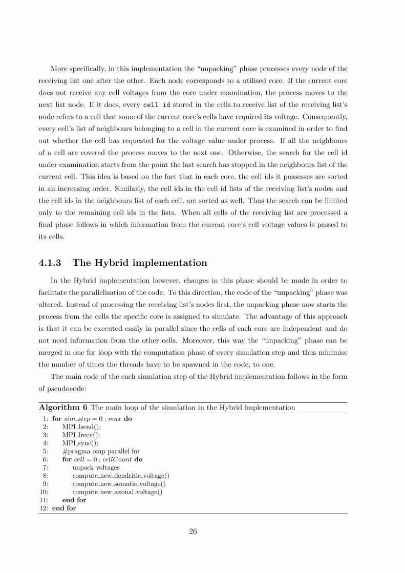
More specifically, in this implementation the “unpacking” phase processes every node of the
receiving list one after the other. Each node corresponds to a utilised core. If the current core
does not receive any cell voltages from the core under examination, the process moves to the
next list node. If it does, every cell id stored in the cells to receive list of the receiving list’s
node refers to a cell that some of the current core’s cells have required its voltage. Consequently,
every cell’s list of neighbours belonging to a cell in the current core is examined in order to find
out whether the cell has requested for the voltage value under process. If all the neighbours
of a cell are covered the process moves to the next one. Otherwise, the search for the cell id
under examination starts from the point the last search has stopped in the neighbours list of the
current cell. This idea is based on the fact that in each core, the cell ids it possesses are sorted
in an increasing order. Similarly, the cell ids in the cell id lists of the receiving list’s nodes and
the cell ids in the neighbours list of each cell, are sorted as well. Thus the search can be limited
only to the remaining cell ids in the lists. When all cells of the receiving list are processed a
final phase follows in which information from the current core’s cell voltage values is passed to
its cells.
4.1.3 The Hybrid implementation
In the Hybrid implementation however, changes in this phase should be made in order to
facilitate the parallelisation of the code. To this direction, the code of the “unpacking” phase was
altered. Instead of processing the receiving list’s nodes first, the unpacking phase now starts the
process from the cells the specific core is assigned to simulate. The advantage of this approach
is that it can be executed easily in parallel since the cells of each core are independent and do
not need information from the other cells. Moreover, this way the “unpacking” phase can be
merged in one for loop with the computation phase of every simulation step and thus minimise
the number of times the threads have to be spawned in the code, to one.
The main code of the each simulation step of the Hybrid implementation follows in the form
of pseudocode:
Algorithm 6 The main loop of the simulation in the Hybrid implementation
1: for sim step = 0 : max do2: MPI Isend();3: MPI Irecv();4: MPI sync();5: #pragma omp parallel for6: for cell = 0 : cellCount do7: unpack voltages8: compute new dendritic voltage()9: compute new somatic voltage()
10: compute new axonal voltage()11: end for12: end for
26
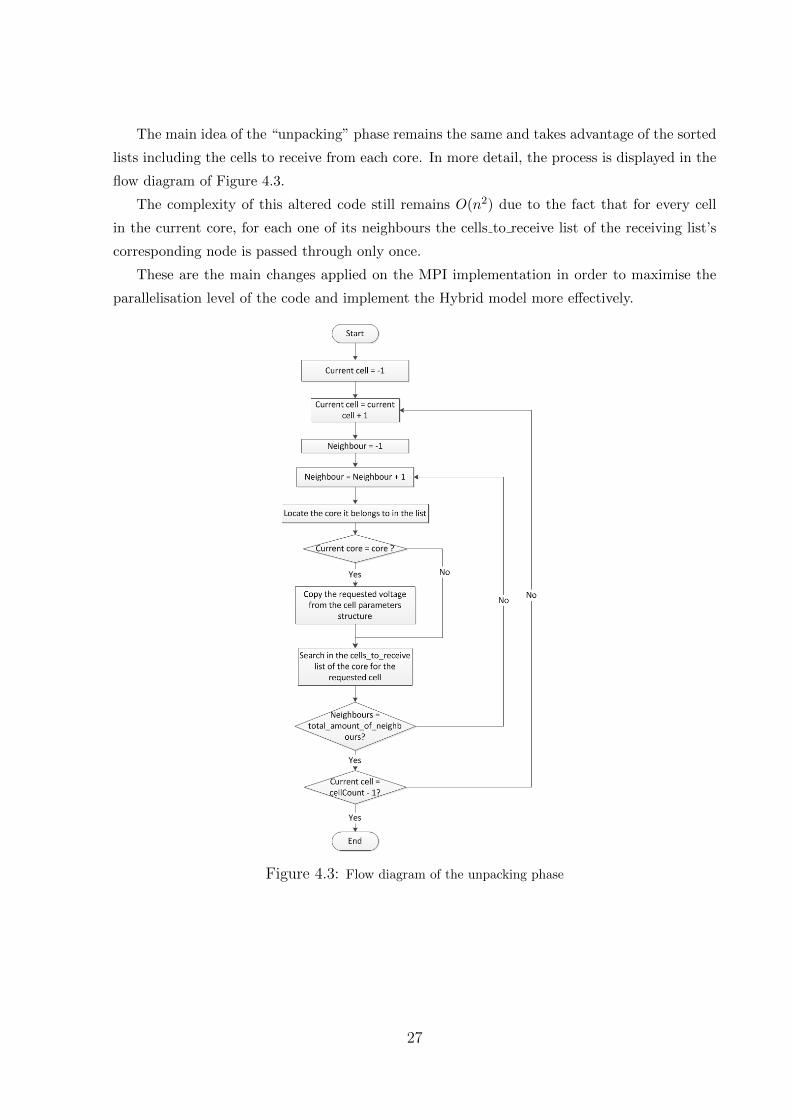
The main idea of the “unpacking” phase remains the same and takes advantage of the sorted
lists including the cells to receive from each core. In more detail, the process is displayed in the
flow diagram of Figure 4.3.
The complexity of this altered code still remains O(n2) due to the fact that for every cell
in the current core, for each one of its neighbours the cells to receive list of the receiving list’s
corresponding node is passed through only once.
These are the main changes applied on the MPI implementation in order to maximise the
parallelisation level of the code and implement the Hybrid model more effectively.
Figure 4.3: Flow diagram of the unpacking phase
27
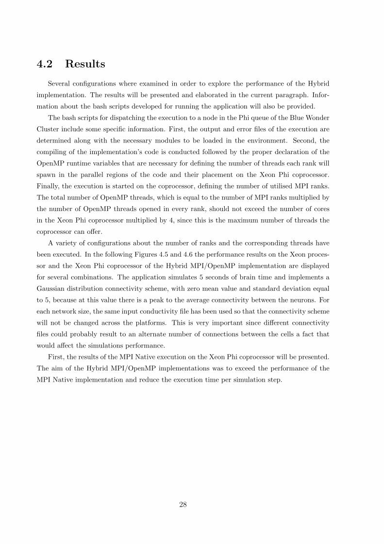
4.2 Results
Several configurations where examined in order to explore the performance of the Hybrid
implementation. The results will be presented and elaborated in the current paragraph. Infor-
mation about the bash scripts developed for running the application will also be provided.
The bash scripts for dispatching the execution to a node in the Phi queue of the Blue Wonder
Cluster include some specific information. First, the output and error files of the execution are
determined along with the necessary modules to be loaded in the environment. Second, the
compiling of the implementation’s code is conducted followed by the proper declaration of the
OpenMP runtime variables that are necessary for defining the number of threads each rank will
spawn in the parallel regions of the code and their placement on the Xeon Phi coprocessor.
Finally, the execution is started on the coprocessor, defining the number of utilised MPI ranks.
The total number of OpenMP threads, which is equal to the number of MPI ranks multiplied by
the number of OpenMP threads opened in every rank, should not exceed the number of cores
in the Xeon Phi coprocessor multiplied by 4, since this is the maximum number of threads the
coprocessor can offer.
A variety of configurations about the number of ranks and the corresponding threads have
been executed. In the following Figures 4.5 and 4.6 the performance results on the Xeon proces-
sor and the Xeon Phi coprocessor of the Hybrid MPI/OpenMP implementation are displayed
for several combinations. The application simulates 5 seconds of brain time and implements a
Gaussian distribution connectivity scheme, with zero mean value and standard deviation equal
to 5, because at this value there is a peak to the average connectivity between the neurons. For
each network size, the same input conductivity file has been used so that the connectivity scheme
will not be changed across the platforms. This is very important since different connectivity
files could probably result to an alternate number of connections between the cells a fact that
would affect the simulations performance.
First, the results of the MPI Native execution on the Xeon Phi coprocessor will be presented.
The aim of the Hybrid MPI/OpenMP implementations was to exceed the performance of the
MPI Native implementation and reduce the execution time per simulation step.
28
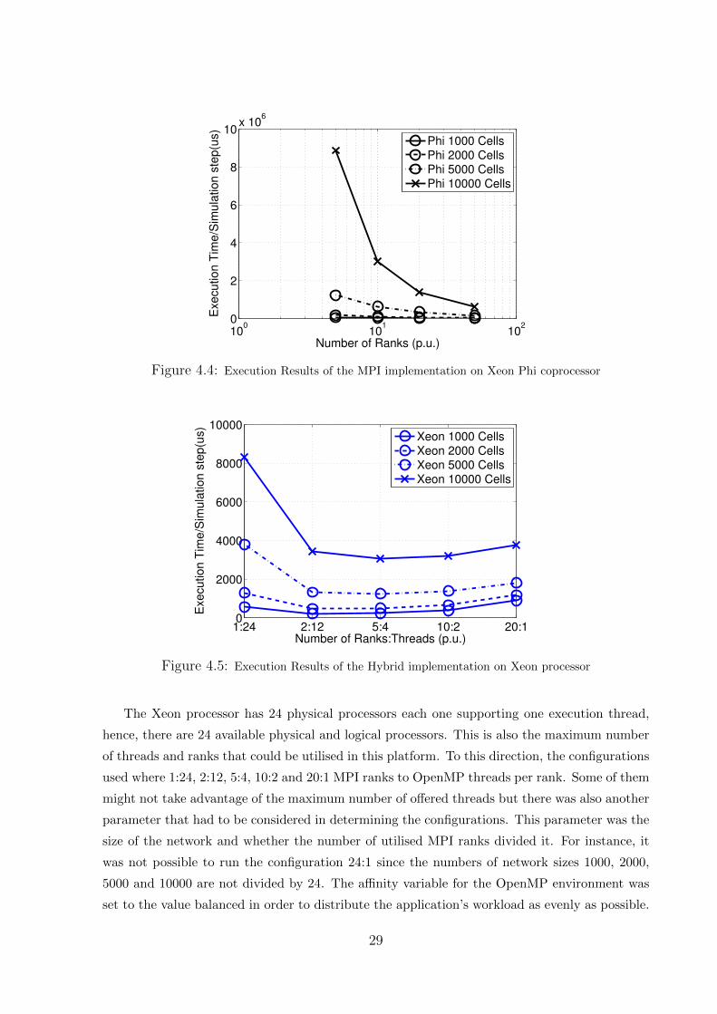
100
101
102
0
2
4
6
8
10x 10
6
Number of Ranks (p.u.)
Exe
cu
tio
n T
ime
/Sim
ula
tio
n s
tep
(us)
Phi 1000 CellsPhi 2000 CellsPhi 5000 CellsPhi 10000 Cells
Figure 4.4: Execution Results of the MPI implementation on Xeon Phi coprocessor
1:24 2:12 5:4 10:2 20:10
2000
4000
6000
8000
10000
Number of Ranks:Threads (p.u.)
Exe
cu
tio
n T
ime
/Sim
ula
tio
n s
tep
(us)
Xeon 1000 CellsXeon 2000 CellsXeon 5000 CellsXeon 10000 Cells
Figure 4.5: Execution Results of the Hybrid implementation on Xeon processor
The Xeon processor has 24 physical processors each one supporting one execution thread,
hence, there are 24 available physical and logical processors. This is also the maximum number
of threads and ranks that could be utilised in this platform. To this direction, the configurations
used where 1:24, 2:12, 5:4, 10:2 and 20:1 MPI ranks to OpenMP threads per rank. Some of them
might not take advantage of the maximum number of offered threads but there was also another
parameter that had to be considered in determining the configurations. This parameter was the
size of the network and whether the number of utilised MPI ranks divided it. For instance, it
was not possible to run the configuration 24:1 since the numbers of network sizes 1000, 2000,
5000 and 10000 are not divided by 24. The affinity variable for the OpenMP environment was
set to the value balanced in order to distribute the application’s workload as evenly as possible.
29
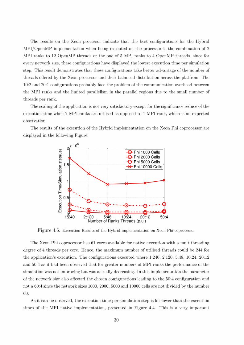
The results on the Xeon processor indicate that the best configurations for the Hybrid
MPI/OpenMP implementation when being executed on the processor is the combination of 2
MPI ranks to 12 OpenMP threads or the one of 5 MPI ranks to 4 OpenMP threads, since for
every network size, these configurations have displayed the lowest execution time per simulation
step. This result demonstrates that these configurations take better advantage of the number of
threads offered by the Xeon processor and their balanced distribution across the platfrom. The
10:2 and 20:1 configurations probably face the problem of the communication overhead between
the MPI ranks and the limited parallelism in the parallel regions due to the small number of
threads per rank.
The scaling of the application is not very satisfactory except for the significance reduce of the
execution time when 2 MPI ranks are utilised as opposed to 1 MPI rank, which is an expected
observation.
The results of the execution of the Hybrid implementation on the Xeon Phi coprocessor are
displayed in the following Figure:
1:240 2:120 5:48 10:24 20:12 50:40
0.5
1
1.5
2x 10
5
Number of Ranks:Threads (p.u.)
Exe
cu
tio
n T
ime
/Sim
ula
tio
n s
tep
(us)
Phi 1000 CellsPhi 2000 CellsPhi 5000 CellsPhi 10000 Cells
Figure 4.6: Execution Results of the Hybrid implementation on Xeon Phi coprocessor
The Xeon Phi coprocessor has 61 cores available for native execution with a multithreading
degree of 4 threads per core. Hence, the maximum number of utilised threads could be 244 for
the application’s execution. The configurations executed where 1:240, 2:120, 5:48, 10:24, 20:12
and 50:4 as it had been observed that for greater numbers of MPI ranks the performance of the
simulation was not improving but was actually decreasing. In this implementation the parameter
of the network size also affected the chosen configurations leading to the 50:4 configuration and
not a 60:4 since the network sizes 1000, 2000, 5000 and 10000 cells are not divided by the number
60.
As it can be observed, the execution time per simulation step is lot lower than the execution
times of the MPI native implementation, presented in Figure 4.4. This is a very important
30
result and shows the compelling improvement of the application’s performance through the
combination of the two programming models. The application displays better performance
when the number of MPI ranks and OpenMP threads are not very different in the terms of
order of magnitude. The best configuration seems to be the 20 MPI ranks with 12 OpenMP
threads each, due to the lowest execution times for three out of four network sizes.
Another point is that the Hybrid MPI/OpenMP implementation on the Xeon processor
displays lower execution time per simulation step that the application when natively executed
on the Xeon Phi. This is due to the fact that in order to fully utilise the capabilities of the
Xeon Phi platform, vectorization techniques should be manipulated a fact that has not been
implemented in the current work. Should these techniques be implemented, the performance of
the Xeon Phi coprocessor would be significantly improved.
31
Chapter 5
OpenMP Implementations
5.1 Development Details
The OpenMP implementation was based on a single-threaded implementation extracted by
the existing MPI implementation [47]. All the MPI commands and directives were removed and
replaced by simpler serial code performing the same operations.
More specifically, in the MPI implementation there is an initial phase in which the commu-
nication list for each core is created, as it has been mentioned in Chapter 4. The list consists
of the necessary information the core needs to exchange with every other utilised core. Two
functions are implemented in this phase. The first creates the list with the data the core has
to send to other cores and the second the data the core receives from other cores. In the first
function, the list is composed of a node for each core employed that contains the core’s id, a
list with the cell ids to send, their dendritic voltages, their total number and a pointer to the
next node in the list. The second list includes a node for each core with the core’s id, the list
of cell ids that the core receives voltages from, the corresponding dendritic voltages, the cells’
total number and a pointer to the next node of the list.
However, since OpenMP is a shared memory programming model, this initial phase can be
more easily performed by using shared variables instead of sending messages. Thus, this phase
is narrowed down to two nested for loops as displayed in the following pseudocode:
32
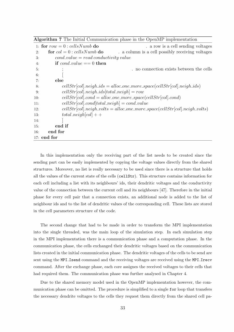
Algorithm 7 The Initial Communication phase in the OpenMP implementation
1: for row = 0 : cellsNumb do . a row is a cell sending voltages2: for col = 0 : cellsNumb do . a column is a cell possibly receiving voltages3: cond value = read conductivity value4: if cond value == 0 then5: ; . no connection exists between the cells6: [7: else8: cellStr[col].neigh ids = alloc one more space(cellStr[col].neigh ids)9: cellStr[col].neigh ids[total neigh] = row
10: cellStr[col].cond = alloc one more space(cellStr[col].cond)11: cellStr[col].cond[total neigh] = cond value12: cellStr[col].neigh volts = alloc one more space(cellStr[col].neigh volts)13: total neigh[col] + +14: ]15: end if16: end for17: end for
In this implementation only the receiving part of the list needs to be created since the
sending part can be easily implemented by copying the voltage values directly from the shared
structures. Moreover, no list is really necessary to be used since there is a structure that holds
all the values of the current state of the cells (cellStr). This structure contains information for
each cell including a list with its neighbours’ ids, their dendritic voltages and the conductivity
value of the connection between the current cell and its neighbours [47]. Therefore in the initial
phase for every cell pair that a connection exists, an additional node is added to the list of
neighbour ids and to the list of dendritic values of the corresponding cell. These lists are stored
in the cell parameters structure of the code.
The second change that had to be made in order to transform the MPI implementation
into the single threaded, was the main loop of the simulation step. In each simulation step
in the MPI implementation there is a communication phase and a computation phase. In the
communication phase, the cells exchanged their dendritic voltages based on the communication
lists created in the initial communication phase. The dendritic voltages of the cells to be send are
sent using the MPI Isend command and the receiving voltages are received using the MPI Irecv
command. After the exchange phase, each core assignes the received voltages to their cells that
had required them. The communication phase was further analysed in Chapter 4.
Due to the shared memory model used in the OpenMP implementation however, the com-
munication phase can be omitted. The procedure is simplified to a single for loop that transfers
the necessary dendrite voltages to the cells they request them directly from the shared cell pa-
33
rameter structure. The arising loop is also merged with the computation’s loop for each cell in
order to increase the parallelism level of the implementation. In this way in every simulation
step for every cell in the grid, the dendritic voltages it requires are copied to its node in the
cell parameters structure directly from the nodes of its neighbouring cells. Then, the new so-
matic, dendritic and axonal voltages of each cell are computed and stored in the cell parameters
structure for the next simulation step.
After making the changes mentioned above, the single threaded implementation was ready
to be transformed into the OpenMP implementation. To that direction, the OpenMP #pragma
omp parallel for directive was used in order for the main loop of the simulation step to
run in parallel. The variables inside the parallel region where defined as shared, private and
firstprivate according to their roles [32]. The OpenMP environmental variables were set accord-
ing to Intel R©’s instructions [28], and the application was tested on both the Xeon processor
and the Xeon Phi coprocessor by setting the OpenMP environment accordingly. The following
pseudocode presents the main loop of the OpenMP implementation, as described above:
Algorithm 8 The main loop of the simulation in the OpenMP implementation
1: #pragma omp parallel for2: for cell = 0 : numberOfCells do3: for neighbour = 0 : total number of neighbours do4: requested neighbour = cellStruct[cell].neighbours ids[neighbour]5: cellSruct[cell].neigh voltages[neighbour] = requested neighbour[voltage]6: end for7: compute new dendritic voltage()8: compute new somatic voltage()9: compute new axonal voltage()
10: end for
5.1.1 Runtime Configuration
In order for the application to run on the Xeon Phi coprocessor, the LD LIBRARY PATH
variable had to be appended with the path of the shared libraries necessary for the OpenMP*
environment. Then, the KMP AFFINITY environmental variable of the Phi OpenMP runtime had
to be set. This variable controls the binding of threads to physical processing units. [32] The
types of affinity used in this implementation are’“balanced” and “compact”. The balanced type
places the threads as evenly as possible on the nodes. The compact type places one thread as
close to the previous one as possible. After a first set of measurements to estimate which affinity
type was more suitable for the application, the performance of the execution was proved better
when balanced affinity was utilised. As a result, this type was therefore used in the performance
34

results presented in this thesis. The verbose modifier before the affinity type might be used
to ask the OpenMP runtime to print information about the binding of the requested threads
to the cores of the current machine [28]. These two types of affinity were explored in order
to see which best fits out application. Another runtime variable was KMP PLACE THREADS which
defines the topology that is going to be used and more specifically the number of cores requested
and the number of threads per core. The OMP NUM THREADS variable determines the number of
threads that will be spawned in the parallel region.The same runtime variables except for the
KMP PLACE THREADS variable are also available on the Xeon processors.
The same OpenMP runtime configuration is used for the Hybrid implementation as well, as
described in Chapter 4.
35
5.2 Results
Multiple configurations of the application were executed on the Xeon processor and the
Xeon Phi coprocessor in order to evaluate the performance of the OpenMP implementation.
The results will be presented and a possible interpretation will be attempted. Some information
about the bash scripts developed for running the application will be provided.
The bash scripts for dispatching the execution to a node in the Phi queue of the Blue Wonder
Cluster include some specific information similar to those mentioned for the execution of the
Hybrid MPI/OpenMP implementation in the corresponding Chapter 4. First, the output and
error files of the execution are determined along with the necessary modules to be loaded in
the environment. Second, the compiling of the implementation’s code is conducted followed
by the proper declaration of the OpenMP runtime variables that are necessary for defining the
number of threads that will be used in the parallel regions, and their placement on the Xeon
Phi coprocessor. The execution is started on the coprocessor. The total number of OpenMP
threads on the Xeon Phi coprocessor can not exceed the number of its cores multiplied by 4,
since this is the maximum number of threads the coprocessor can offer. Similarly, when the
OpenMP implementation is executed on the Xeon processor, the number of utilised threads can
not be greater than the number of its cores multiplied by 1.
In the following Figure 5.1 the execution results of both the Xeon processor and the Xeon Phi
coprocessor are be presented. The application simulates 5 seconds of brain time and implements
a Gaussian distribution connectivity scheme, with zero mean value and standard deviation equal
to 5, because at this value there is a peak to the average connectivity between the neurons. All
the execution instances on both platforms are using the same connectivity input files for the
corresponding network sizes, to reassure that there will be no variations in the execution time
due to different application’s workload. The connectivity file affects the number of connections
between the neurons on the grid and therefore the computational demand of the simulation.
36
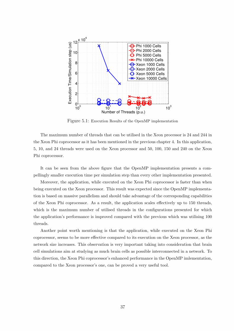
100
101
102
103
0
2
4
6
8
10
12x 10
4
Number of Threads (p.u.)
Exe
cu
tio
n T
ime
/Sim
ula
tio
n s
tep
(u
s)
Phi 1000 CellsPhi 2000 CellsPhi 5000 CellsPhi 10000 CellsXeon 1000 CellsXeon 2000 CellsXeon 5000 CellsXeon 10000 Cells
Figure 5.1: Execution Results of the OpenMP implementation
The maximum number of threads that can be utilised in the Xeon processor is 24 and 244 in
the Xeon Phi coprocessor as it has been mentioned in the previous chapter 4. In this application,
5, 10, and 24 threads were used on the Xeon processor and 50, 100, 150 and 240 on the Xeon
Phi coprocessor.
It can be seen from the above figure that the OpenMP implementation presents a com-
pellingly smaller execution time per simulation step than every other implementation presented.
Moreover, the application, while executed on the Xeon Phi coprocessor is faster than when
being executed on the Xeon processor. This result was expected since the OpenMP implementa-
tion is based on massive parallelism and should take advantage of the corresponding capabilities
of the Xeon Phi coprocessor. As a result, the application scales effectively up to 150 threads,
which is the maximum number of utilised threads in the configurations presented for which
the application’s performance is improved compared with the previous which was utilising 100
threads.
Another point worth mentioning is that the application, while executed on the Xeon Phi
coprocessor, seems to be more effective compared to its execution on the Xeon processor, as the
network size increases. This observation is very important taking into consideration that brain
cell simulations aim at studying as much brain cells as possible interconnected in a network. To
this direction, the Xeon Phi coprocessor’s enhanced performance in the OpenMP imlementation,
compared to the Xeon processor’s one, can be proved a very useful tool.
37
Chapter 6
Conclusion
6.1 General Remarks
It can be generally stated that the current thesis has achieved its goal since the implemen-
tations developed managed to improve the legacy MPI code’s performance to a great amount.
Altering the topology of the simulated cell networks from two-dimensional regions to three-
dimensional pieces of brain matter contributes significantly to the direction of implementing more
realistic brain cell simulations that have a greater physical meaning for the neuroscientists.
Furthermore, the Hybrid MPI/OpenMP implementation’s results confirmed the hypothesis
that the performance of the application would be improved by utilising OpenMP threads in each
MPI rank for the execution of some previously serial parts of the code. Indeed, the performance
of the Hybrid implementation on both the Xeon processor and the Xeon Phi coprocessor was
advanced by an order of magnitude compared to the MPI native implementation. The imple-
mentation scales significantly when the number of the utilised OpenMP threads becomes similar
to the number of the MPI ranks used. The best configurations that emerged were 20 MPI ranks
with 12 OpenMP threads and 10 MPI ranks with 24 OpenMP threads per rank for the Xeon
Phi coprocessor. For the Xeon processor, the best configurations were proven to be the one with
2 MPI ranks and 12 OpenMP threads and the one with 5 MPI ranks and 4 OpenMP threads
per rank.
Finally, the OpenMP implementation, succeeded in achieving the lowest execution time per
simulation step among the other implementations both on the Xeon processor and on the Xeon
Phi coprocessor. This fact indicates the massively parallel aspect of our Inferior Olive simu-
lation’s application which had not been efficiently explored and effectively used so far. The
application is considered to be a message-based application but in single-node systems the over-
head introduced by the MPI runtime due to buffer initialisations and process communication
is overwhelming the OpenMP overhead caused by the cache coherence protocols. Additionally,
the satisfying performance of the implementation as the network size increases is very promis-
38
ing for the effort towards simulating bigger brain cell networks. The Xeon Phi coprocessor’s
parallel capabilities have proven to be very effective and worth exploring in order to enhance
the performance of our application comparing to the limited capabilities of the Xeon processor
alone in simulating large cell networks as it has been shown by the performance results of the
OpenMP implementation.
6.2 Development Challenges
The challenges the author had to face in the Hybrid implementation were various. First,
developing a better way to rewrite the unpacking phase to increase the parallelisation of the
code was a very demanding aspect. Furthermore, there was some difficulty in creating the bash
scripts required to run the application since the environment variables of the OpenMP runtime,
further elaborated in Chapter 5, had to be carefully set to the desired values.
During working on the OpenMP implementation there were also some challenges. It was
essential to properly locate the OpenMP shared libraries since it was impossible to run the
application without setting the corresponding variable. Moreover, the programmer had to be
very cautious with the variables in the parallel region and how to declare them since this was
very important for the correct execution of the application. Finally, the programmer had to
meticulously examine their code to ensure that they have obtained maximum parallelism of the
application.
6.3 Future Work
The current work can be expanded towards various directions:
An urging matter that requires further examination is a memory leak problem that has been
observed. Excessive memory demand has been noticed in the MPI-based implementations that
do not use the extra memory allocated. This is due probably to an existing bug and affects
the execution of large jobs leading implementations to crash occasionally, due to Phi’s limited
memory.
Exploring the vectorization capabilities of the Xeon Phi architecture will contribute to the
efficient enhancement of the application’s performance when executed on the Xeon Phi copro-
cessor, since the full spectrum of optimization techniques offered by the platform will have been
utilised. This optimizations can be applied on the current OpenMP and Hybrid implementa-
tions. Another direction can be the development of an implementation based on the offload
programming model of the architecture in order to study the performance of this programming
paradigm as well.
39

The cell generator code can be expanded to include a broader variety of three-dimensional
topologies such as a spheric or a cylindric topology. The connectivity schemes can also be en-
riched and involve the user of the application to a greater amount in determining the connections
between the neurons of the grid.
A graphic three-dimensional representation of the results of the simulation over execution
time can be developed in order to provide visual material to the neuroscientists about the
simulation’s progress.
Finally, multi-node approaches can be explored in order to further examine the Xeon - Xeon
Phi architecture’s capabilities to bolster the applications performance.
40
Bibliography
[1] A.L.Hodgkin A.F.Huxley. ”A quantitative description of membrane current and its ap-
plication to conduction and exitation in nerve”. Physiological Laboratory, University of
Cambridge, 1952. xiixii, 1, 6, 12
[2] “Blue Brain Project”. http://bluebrain.epfl.ch. 1
[3] Antony Neville Burkitt. “A review of the Integrate-and-fire Neuron Model: I. Homogeneous
Synaptic Input”. Biological Cybernetics, 2006. viiiviii, 6
[4] Hartree Centre. “Hartree Centre user Guide chapter E2 Xeon Phi system”. Technical
report, Hartree Centre, 2015. 21
[5] “Charm ++ parallel programming framework”. http://charmplusplus.org. 11
[6] V.Agarwal L.Lurng-Kuo D.A.Bader. “Financial modeling on the cell broadband engine”.
IEEE International Symposium on Parallel and Distributed Processing, 2008. xx, 7
[7] Peter Dayan. “Levels of analysis in neural modeling”. Encyclopedia of Cognitive Science,
2006. viiiviii, viiiviii, 4, 5, 6
[8] C.Coarfa J.M. Mellor-Crummey D.G.Chavarria-Miranda. “An evaluation of global address
space languages: Co-array fortran and Unified Parallel C”. Conference Paper, 2015, Jan-
uary. 11
[9] E.Izhikevich. “Simple model of spiking neurons”. IEEE Transactions on Neural Networks
Vol.14 No. 6, 2003. ixix, 6
[10] Chris I. De Zeeuw et al. “Microcircuitry and function of the inferior olive”. Trends In
Neuroscience, 1998. 1, 12
[11] F. Benedetti et al. “Inferior olive lesion induces long-lasting functional modification in the
Purkinje cells”. Experimental Brain Research, 1984. 12
[12] K.Asanovic R. Bodik J.Demmel e.t.c. “A view of the parallel computing landscape”. Com-
munications of the ACM, 2009. ixix, 7
41
[13] L.Hochstein J.Carver F.Shull S.Asgari V.Basili etc. “Parallel Programmer Productivity:
A Case Study of Novice Parallel Programmers”. SC ?05: Proceedings of the ACM/IEEE
Conference on Su- percomputing, 2005. 8
[14] P.Ruther A.Aarts O.Frey S.Herwik etc. “The NeuroProbes Project - Multifunctional Probe
Arrays for Neural Recording and Simulation”. IFESS Conference, 2008. 6
[15] Khronos Group. “The open standard for parallel programming of heterogeneous systems”.
https://www.khronos.org/opencl/. 11
[16] R.S. Dow H. Leiner, A.Leiner. “Cognitive and language functions of the human cerebellum”.
Trends in Neurosciences, 1993. 1
[17] “The Hartree Centre”. http://www.stfc.ac.uk/innovation/ways-to-work-with-us/
the-hartree-centre/. xvxv, 21
[18] “The Hartree Centre’s scripts for running MPI and OpenMP applications in the Phi queue
”. http://community.hartree.stfc.ac.uk/wiki/site/admin/jobs2.html. 21
[19] Coordinator of the Project Herc Neves. “The NeuroProbes Project”. http:
//cordis.europa.eu/fp7/ict/micro-nanosystems/docs/4thmnbs-slides/
4thmnbs2010-day1-neuroprobes-neves_en.pdf. 6
[20] J.Igarashi O.Shouno T.Fukai H.Tsujino. “Real-time simulation of a spiking neural network
model of the basal ganglia sircuitry using general purpose computing on graphics processing
units”. Neural Networks, 2011. 4
[21] B.Baas Z.Yu M.Meeuwsen O.Sattari R.Apperson E.Work J.Webb M.Lai T.Mohsenin
D. Truong J.Cheung. “AsAP: A Fine-Grained Many-Core Platform for DSP Applications”.
IEEE Micro, vol.27, no. 2, pp. 34-45, March/April 2007. xx, 7
[22] J.KTsotsos. “Toward a Computational Model of Visual Attention”. Early vision and
beyond, 1995. viiiviii, 5
[23] Ringo J.L. “Neuronal interconnection as a function of brain size”. Brain, Behavior and
Evolution, 1991. xiixii, 13
[24] J.Reinders. “An Overview of Programming for Intel Xeon processors and Intel Xeon Phi
coprocessors”. Technical report, Intel Labs, 2012. 17
[25] J.D.Cohen T.S.Braver J.W.Brown. “Computational perspectives on dopamine function in
prefrontal cortex”. Current Opinion in Neurobiology, 2002. viiiviii, 5
[26] B.Barney Lawrence Livermore National Laboratory. “Introduction to Parallel Computing”.
https://computing.llnl.gov/tutorials/parallel_comp/#SharedMemory. vv, vv, 9
42
[27] B.Barney Lawrence Livermore National Laboratory. “Message Passing Interface (MPI)”.
https://computing.llnl.gov/tutorials/mpi/#What. xixi, 8, 10
[28] Intel Labs. “Affinity Types of the OpenMP* Runtime”. https://software.intel.com/
en-us/node/522691AFFINITY_TYPES. 34, 35
[29] Intel Labs. “Intel Forums for the MIC architecture”. https://software.intel.com/
en-us/forums/intel-many-integrated-core. 20
[30] Intel Labs. “Intel Many Integrated Core Architecture - Advanced”. http://www.intel.
com/content/www/us/en/architecture-and-technology/many-integrated-core/
intel-many-integrated-core-architecture.html. 17
[31] Intel Labs. “Intel Threading Building Blocks (Intel TBB)”. https://software.intel.
com/en-us/intel-tbb. xixi, 11
[32] Intel Labs. “Thread Affinity Control”. https://software.intel.com/en-us/articles/
openmp-thread-affinity-control. 34
[33] Intel Labs. “The Intel Xeon Phi product family: Highly parallel processing for unparalleled
discovery”. Technical report, Intel Labs, 2013. 2
[34] S.U.Thiagarajan C.Congdon S.Naik L.Q.Nguyen. “Intel Xeon Phi Coprocessor Developer’s
Quick Start Guide”. Technical report, Intel Labs, 2013. vv, vv, 18, 19, 20
[35] G. E. Moore. “cramming more components onto integrated circuits? Electronics, vol. 38,
no. 8, pp. 114?117, 1965. ixix, 7
[36] “Neuron Modelling”. http://www.explorecuriocity.org/content.aspx?contentid=
2282. vv, vv, xiixii, 13
[37] NVIDIA. “NVIDIA CUDA Zone”. https://developer.nvidia.com/cuda-zone. 9
[38] NVIDIA. “NVIDIA CUDA C Programming Guide”. Technical report, NVIDIA, 2012,
April 16. xiixii, 11
[39] “CUDA tooklit documentation NVIDIA”. https://docs.nvidia.com/cuda/
cuda-c-programming-guide/. xixi, 11
[40] “The OpenMP API specification for parallel programming”. http://openmp.org/wp/.
xixi, 8, 10
[41] “OpenMPI v1.8.8 documentation”. https://www.open-mpi.org/doc/v1.8/. 10
43
[42] Randall C. O’Reilly and Yuko Munakata. “Computational Explorations in Cognitive Neu-
roscience: Understanding the Mind by Simulating the Brain”. MPI Press, 2000. xiixii,
12
[43] Andreas Pantelopoulos. Asynchronous Inter-core Communication in The Inferior Olive
Simulator For The Intel Scc. http://artemis-new.cslab.ece.ntua.gr:8080/jspui/
handle/123456789/7207. 14
[44] Shameen Akhter Jason Roberts. “Multi Core Programming”. Intel Press, 2006. vv, vv,
ixix, ixix, xx, 7, 8
[45] J.Held S.Koehl. “Introducing the Single-chip Cloud Computer”. Technical report, Intel
Labs, 2010. 9
[46] “The SSH protocol”. http://www.ietf.org/rfc/rfc4251.txt. 19
[47] George T.Chatzikonstantis. “Energy Aware Mapping of a biologically accurate Inferior
Olive cell model on the Single-chip Cloud Computer”. http://artemis-new.cslab.ece.
ntua.gr:8080/jspui/handle/123456789/6827. iiii, vv, viivii, xiiixiii, 2, 13, 14, 24, 32, 33
[48] M.Barth M.Byckling N.Ilieva S.Saarinen M.Schiephake V.Weinberg. “Best Practice Guide
Intel Xeon Phi”. Technical report, Intel Labs, 2014. 17, 19
[49] “Infoli Simulator Bitbucket Wiki”. https://bitbucket.org/Felix999/infoli_mpi/
wiki/Home. xvixvi, 23, 25
[50] D.B. Kirk W.W.Hwu. “Programming Massively Parallel Processors: A Hands-on Ap-
proach”. Elsevier Inc., 2013, 2010. xixi, xixi, 10, 11
[51] “The Intel Xeon processor E5-2609”. http://ark.intel.com/products/75787/
Intel-Xeon-Processor-E5-2609-v2-10M-Cache-2_50-GHz. 21
[52] “The Intel Xeon processor E5-2697”. http://ark.intel.com/products/75283/
Intel-Xeon-Processor-E5-2697-v2-30M-Cache-2_70-GHz. 21
[53] Susan Young. “Brain Implant detects, responds to Epilepsy”. MIT Technology Review,
2012, October 12. 1
[54] R.D. Blumofe C.F.Joerg B.C.Kuszmaul C.E.Leiserson K.H.Randall Y.Zhou. “Cilk: An Ef-
ficient Multithreading Runtime System”. Technical report, MIT Laboratory for Computer
Science, 1996, October 17. 10
44