Industrial piston air compressors Model:...
42
Operating instructions Industrial piston air compressors Model: K335 Web Site: www.kelloggcompressor.com Issue: 06/2010
Transcript of Industrial piston air compressors Model:...
Operating instructions
Industrial piston air compressors
Model: K335
Web Site: www.kelloggcompressor.com
Issue: 06/2010
Contents Pump service manual
Contents Page
SECTION Ι ..............................................................................................................................................................................................................................1
INTRODUCTION ....................................................................................................................................................................................................................1
UNPACKING AND HANDLING ...........................................................................................................................................................................................2
APPROPRIATE USE ...............................................................................................................................................................................................................4
SYMBOLS USED ....................................................................................................................................................................................................................5
SYMBOLS USED ....................................................................................................................................................................................................................5
SYMBOLS ON THE COMPRESSOR ..........................................................................................................................................................................................6
SAFETY GUIDE ......................................................................................................................................................................................................................8
SECTION ΙΙ.............................................................................................................................................................................................................................1
INSTALLATION INSTRUCTION ..........................................................................................................................................................................................1
TECHNICAL DATA .................................................................................................................................................................................................................1
EXPLODE DRAWING..............................................................................................................................................................................................................2
BILL OF MATERIAL LIST........................................................................................................................................................................................................3
INSPECTION ..........................................................................................................................................................................................................................5
HEAD UNLOADER ................................................................................................................................................................................................................7
CENTRIFUGAL UNLOADER..............................................................................................................................................................................................11
OPERATION ..........................................................................................................................................................................................................................14
SECTION ΙΙΙ...........................................................................................................................................................................................................................1
PARTS KITS.............................................................................................................................................................................................................................1
OVERHAUL KIT ....................................................................................................................................................................................................................1
RING SET..............................................................................................................................................................................................................................1
VALVE SET ...........................................................................................................................................................................................................................1
GASKET SET.........................................................................................................................................................................................................................1
BOLT TORQUE CHART.........................................................................................................................................................................................................2
DISASSEMBLE PUMP ...........................................................................................................................................................................................................3
ASSEMBLE PUMP..................................................................................................................................................................................................................5
TROUBLESHOOTING ...........................................................................................................................................................................................................7
MAINTENANCE .....................................................................................................................................................................................................................7
GENERAL..............................................................................................................................................................................................................................7
SAFETY INFORMATION .........................................................................................................................................................................................................8
CHECK OIL LEVEL ................................................................................................................................................................................................................8
CHECK AND CLEAN COMPRESSOR VALVES.........................................................................................................................................................................10
CHECK THE SAFETY VALVE ................................................................................................................................................................................................11
CHANGE OIL .......................................................................................................................................................................................................................14
CHECK AND CHANGE AIR FILTER........................................................................................................................................................................................14
MAINTENANCE SCHEDULE.............................................................................................................................................................................................15
LIST OF MAINTENANCE AND SERVICE WORK ...........................................................................................................................................................16
Section I Pump Operation Manual
1
Introduction
These operating instructions form part of the machine and must be made available to the compressor operating personnel at all times. In order to receive maximum performance and long life from your compressor, the following instructions should carefully read and all points regarding installation and operation of the unit should be noted and observed .careful reading of this manual, prior to connecting anything to the motor or compressor, will pay dividends in long term trouble-free operation.
Section I Pump Operation Manual
2
Unpacking and Handling
Occasionally damage will occur during shipping. Be sure to carefully inspect the unit before unpacking and after unpacking BEFORE you sign the receiver. If any has occurred, document it with the trucking firm immediately. Contact your KELLOGG representative for assistance.
To move your compressor to its installation site we recommend that you leave the unit on its shipping skid as long as possible. The forks should be extended the width of the compressor and padding should be placed between the compressor and the fork truck boom.
If it is necessary to lift the compressor with a crane, we recommend the use of spreader bar and chains. The spreader bar should be greater than the width of the compressor and padding placed on the edges to prevent chain damage.
DO NOT UTILIZE THE PUMP OR DRIVE AS A LIFT POINT
Procedure for Handling Damaged Shipments
1. The customer, at the receiving point, MUST inspect each shipment for damage.2. If the shipment is damaged, the customer should so note it on the freight bill.3. The customer should request an inspector from the freight company to inspect the
equipment immediately. It is best to send a confirming letter with the followinginformation:a. Freight bill number. b. Date delivered - shipper's name & address.c. Description of item(s) damaged.d. Description of damage (a Polaroid picture if possible).e. A copy of your invoice for the equipment.
4. After inspection, (before the inspector leaves):a. Get a copy of the inspection report.b. Request the unit be shipped back "free astray".c. Request a credit for the original freight bill.
5. Call the factory and:a. Get a Return Material Authorization (RMA number).b. Give a purchase order for repair. The purchase order should refer to the item and
trucker claim.
Section I Pump Operation Manual
3
6. We will accept the shipment back, repair (under normal conditions) and return it within (7)seven working days.
7. We will invoice the customer for the repair, which will then become part of your claim.The Invoice must be presented to the trucking claim department along with their claimform.
8. We suggest if the trucker does not pay within 30 days that you call and / or write the ICC making a formal complaint of poor service. Also advise KELLOGG in writing for follow-up.If damage can be repaired at the receiving point, follow Procedure 1, steps 1 through 4a. Repair the unit and make out a detailed invoice to the trucker showing labor hours, labor rate, materials used, and cost of materials.
Storage In some cases it may necessary to store the compressor for extended periods of several
months before placing the unit in operation. When this is required do the following: Cover and seal all machine openings to prevent the entrance of water and dirt. Cover all openings in open drip proof motors to prevent the entrance of rodents. If the storage conditions are below freezing, drain off the tank, traps, and attendant piping. We do not recommend outside storage. Cover with a waterproof tarpaulin that can easily be removed for in storage maintenance. While in storage, every two to three months rotate the compressor and motor by hand to prevent flat spots on the bearings that will lead to premature failure. At the end of the storage period, follow the uncrating and start-up procedures. If the unit has been stored for more than eighteen months you should contact KELLOGG before restarting the compressor.
Section I Pump Operation Manual
4
Appropriate use
As standard, KELLOGG piston compressors are intended for the compression of ambient air. The air may not contain any aggressive or combustible mixtures.
The pressure chambers of the compressor are oil-lubricated. Therefore, the compressed air produced may only be used as breathing air or come into contact with food if it has been treated beforehand.
WARNING
As standard this KELLOGG piston compressor is not of an explosion-protected design and it may not be operated in areas subject to explosion hazards!
Section I Pump Operation Manual
5
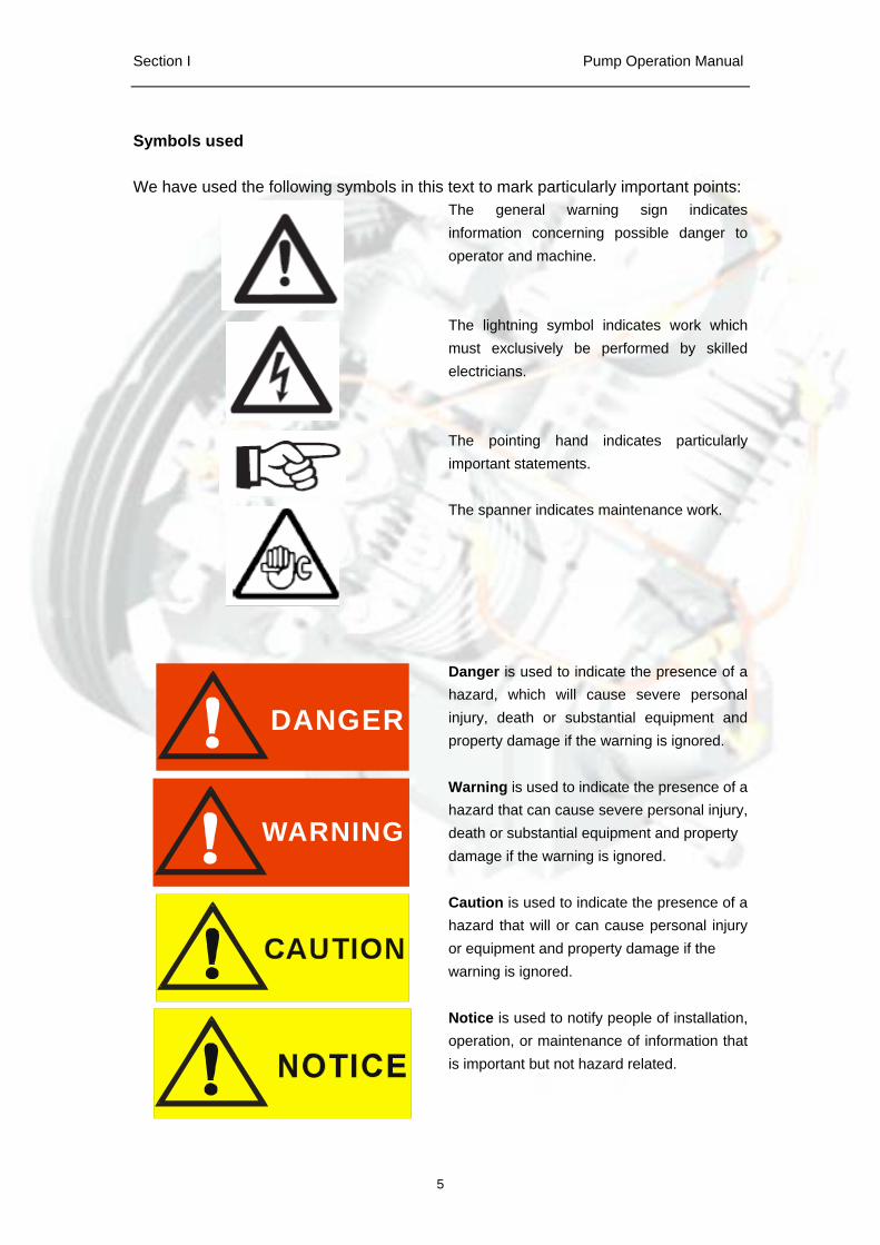
Symbols used
We have used the following symbols in this text to mark particularly important points: The general warning sign indicates information concerning possible danger to operator and machine.
The lightning symbol indicates work which must exclusively be performed by skilled electricians.
The pointing hand indicates particularly important statements.
The spanner indicates maintenance work.
DANGER
Danger is used to indicate the presence of a hazard, which will cause severe personal injury, death or substantial equipment and property damage if the warning is ignored.
WARNING
Warning is used to indicate the presence of a hazard that can cause severe personal injury, death or substantial equipment and property damage if the warning is ignored.
Caution is used to indicate the presence of a hazard that will or can cause personal injury or equipment and property damage if the warning is ignored.
Notice is used to notify people of installation, operation, or maintenance of information that is important but not hazard related.
Section I Pump Operation Manual
6
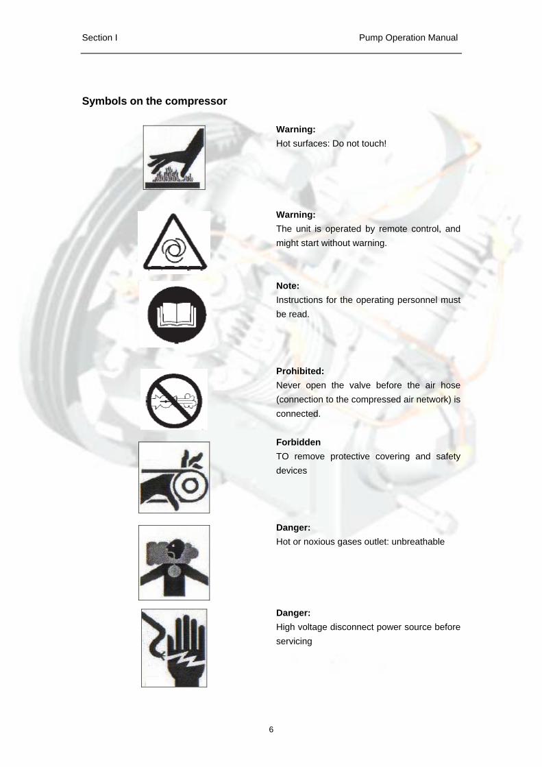
Symbols on the compressor
Warning: Hot surfaces: Do not touch!
Warning: The unit is operated by remote control, and might start without warning.
Note: Instructions for the operating personnel must be read.
Prohibited: Never open the valve before the air hose (connection to the compressed air network) is connected.
Forbidden TO remove protective covering and safety devices
Danger: Hot or noxious gases outlet: unbreathable
Danger: High voltage disconnect power source before servicing
Section I Pump Operation Manual
7
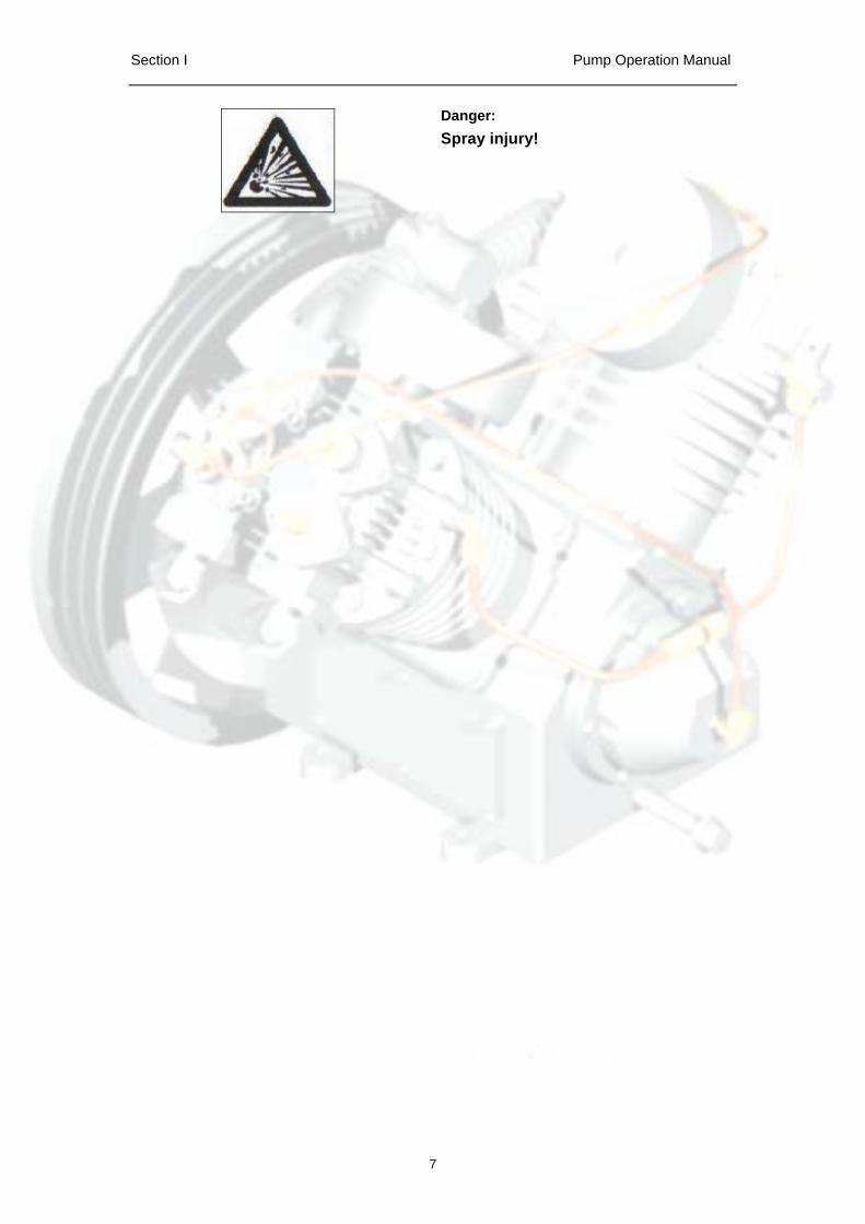
Danger: Spray injury!
Section I Pump Operation Manual
8
Safety Guide
Compressor Safety Precautions
DANGER
An air compressor is a dynamic piece of machinery needing the same common sense safety precautions that should be observed with any operating machinery. Careless operation or maintenance is hazardous to personnel.
WARNING
In addition to the obvious safety rules that should be followed with machinery, we recommend the following additional safety precautions.
1. Read and understand all instructions completely before operating this compressor.2. Disengage power mains and disconnect power lines to the machine, if used, prior to
attempting to work or perform maintenance on this unit.3. Open tank discharge valve and relieve all pressure from tank and compressor lines.
Do not attempt to remove any pressurized system parts without first relieving thepressure within the unit.
4. Do not attempt to service any part while the machine is in operation.5. Do not operate the compressor at pressures in excess of its indicated rating on the
compressor nameplate.6. Do not operate the compressor at speeds in excess of its indicated rating on the
compressor nameplate.7. Do not remove guards, shields, or screens while the compressor is operating. If
removed for maintenance replace before resuming operation.8. Observe the delivery pressure gauge daily to be sure the automatic control system
is operating within proper limits. 9. Periodically check all safety and relief devices for proper operation.10. Do not play with compressed air. Pressurized air can cause serious injury or death
to personnel.11. Be sure that no tools, rags, or loose parts are left on the compressor or drive parts.
Section I Pump Operation Manual
9
12. Do not use flammable solvents for cleaning parts.13. Exercise cleanliness during maintenance and when making repairs.
Keep dirt away from parts and exposed openings by covering with a clean cloth orKraft paper.
14. Install pressure relief valves in any isolatable piping in the plant system.15. Do not operate the compressor in areas where there is the possibility of ingesting
flammable or toxic gases.16. Check pipe for any signs of wear or deterioration before each use and make
certain that all connections are secure. 17. Observe the prescribed maintenance intervals.18. Only use genuine KELLOGG parts.19. Only use KELLOGG compressor oils and operating material recommended by
KELLOGG.20. Strictly observe the effluent disposal laws of your local authority when disposing ofcondensate!
Make sure to investigate the code requirements to ensure compliance prior to operating the compressor.
The owner, lessor, or operator of this compressor is hereby notified and forewarned that any failure to observe these safety precautions may result in injury, death and/or property damage.
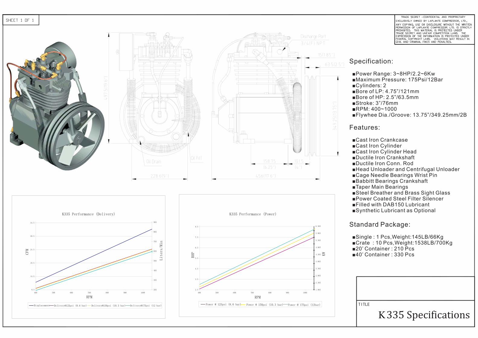
Specification:
Features:
Standard Package:
■Power Range: 3~8HP/2.2~6Kw■Maximum Pressure: 175Psi/12Bar■Cylinders: 2■Bore of LP: 4.75”/121mm■Bore of HP: 2.5”/63.5mm■Stroke: 3”/76mm
RPM: 400~1000■Flywhee Dia./Groove: 13.75”/349.25mm/2B
■Cast Iron Crankcase■Cast Iron Cylinder■Cast Iron Cylinder Head■Ductile Iron Crankshaft■Ductile Iron Conn. Rod■Head Unloader and Centrifugal Unloader■Cage Needle Bearings Wrist Pin■Babbitt Bearings Crankshaft■Taper Main Bearings■Steel Breather and Brass Sight Glass■Power Coated Steel Filter Silencer■Filled with DAB150 Lubricant■Synthetic Lubricant as Optional
■Single : 1 Pcs,Weight:145LB/66Kg■Crate : 10 Pcs,Weight:1538LB/700Kg■20’ Container : 210 Pcs■40’ Container : 330 Pcs
■
K335 Performance (Delivery)
9.5
14.5
19.5
24.5
29.5
34.5
400 500 600 700 800 900 1000
RPM
CFM
283
383
483
583
683
783
883
983
Liters/Min
Displacement Delivery@125psi (8.6 bar) Delivery@150psi (10.3 bar) Delivery@175psi (12 bar)
K335 Performance (Power)
2.5
3.5
4.5
5.5
6.5
7.5
8.5
400 500 600 700 800 900 1000
RPM
BHP
1.865
2.365
2.865
3.365
3.865
4.365
4.865
5.365
5.865
6.365
KW
Power @ 125psi (8.6 bar) Power @ 150psi (10.3 bar) Power @ 175psi (12bar)
K
Section II Pump Operation Manual
2
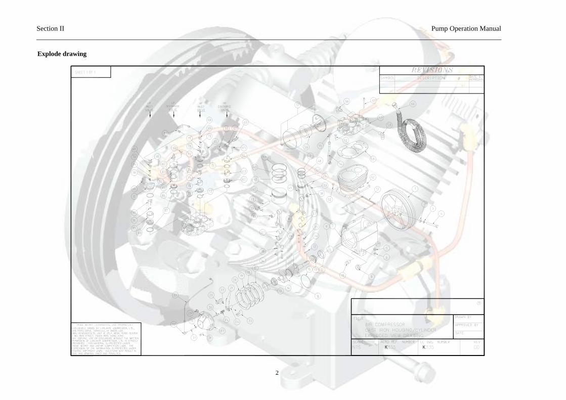
Explode drawing

Section II Pump Operation Manual
3
Bill of material list
Item LAP# Description QTY Item LAP# Description QTY
A 010013Overhaul Kit:Include 1 of Item56,57,B,C,D 48 719033 Bottom Compression Ring HP 1
B 010014Ring Set:Include 1 of Item42,43,44,47,48,49 49 719032 Top Compression Ring HP 1
C 010015Valve Set:Include 1 of Item62,73,86,88 50 110131 SKT Head Capscrew 5/16-18X1 2
D 010016Gasket Set:Include 1 of Item17,18,19,20,51,53 51 070187 Base Gasket 1
1 713007 Flywheel 13.75" 2B 1 52 711004 Cylinder 12 120066 Fly Wheel Nut 1/2-13 1 53 070190 Head Gasket 13 130076 Flywheel Lockwasher 1/2 1 54 725003 Breather Tube 14 110133 Pulley Bolt 1/2-13x3 1/2 1 55 718016 Elbow Breather Connector 15 140038 Oil Filler Plug 1 56 712134 Filter Element 16 140036 Oil Filler Plug Gasket 1 57 712113 Filter 17 708008 Base And Cup Assembly 1 58 718011 Intercooler Connector 28 060300 Seal Oil 1 59 710002 Cylinder Head 19 714004 Oil Level Sight Glass; Copper 1 60 706006 Intercooler Assembly 110 140037 Oil drain Plug 3/8" NPT 1 61 110127 Head Bolt 5/16-18x1 811 726003 Hold Down Cover LP Inlet 1 62 727034 Valve Assembly LP Discharge 112 080033 Woodruff Key #26 1 63 727021 Cage L.P. Discharge 113 050800 Cone Bearing 2 64 110139 Hold Down Cover HP Discharge 114 050801 Bearing 2 65 110128 Hex head Capscrew 5/16-18x3/4 815 709008 Oil Feeder Ring 1 66 722008 Safety Valve 116 709100 Crankshaft & Taper bearing (inc. cu 1 67 718202 T-Fitting(1/4x1/4(M)X1/4) 117 070185 End Cover Gasket .005 2 68 718012 Tube Ell. 1/4X1/4 NPT 118 070191 End Cover Gasket .006 1 69 718013 Bushing 3/8 NPT x 1/4 NPT 219 070291 End Cover Gasket .003 2 70 726004 Plunger 220 070186 End Cover Gasket .0015 2 71 060075 O Ring LP Cover 221 110129 Rivet 2 72 070189 Valve Gasket HP 222 723007 Bumper Spring 2 73 727023 Valve Assembly LP Inlet 123 728006 Weight Unloader 2 74 727020 Cage LP Inlet 224 726010 Holder Unloader 1 75 120068 Locknut 225 723008 Spring 1 76 726007 Fingers H.P. 126 726002 Plunger 1 77 726006 Hold Down Cover HP Inlet 227 701011 End Cover 1 78 723011 Spring 228 110126 End Cover Capscrew 5/16-18x1 6 79 060076 O Ring Plunger 229 718006 Breather Connector 1 80 725006 Unloader Tube 130 120069 Locknut 1 81 718014 Tube Tee 1/4x1/4x1/4 NPT 131 725005 Unloading Tube 1 82 722009 Safety Valve 132 727040 Elbow Valve & Unloader 1 83 727058 Hold Down Cover LP Discharge 133 725005 Unloading Tube 1 84 060074 O Ring HP Cover 234 110124 Rod Bolt 5/16-24 x 1 3/8 4 85 727025 Cage HP Discharge 135 130073 Lockwasher 5/16 4 86 727038 Valve Seat HP Discharge 136 705202 Connecting Rod 2 87 070188 Valve Gasket LP 237 050148 Bearing Inserts 4 88 727039 Valve Assembly Hp Inlet 138 050146 Needle Bearing Wristpin LP & HP 2 89 727022 Cage HP Inlet 139 100103 Rollpin LP &HP 1 90 726005 Fingers L.P. 140 729003 Wristpin LP 141 719031 Piston LP 142 719034 Oil Conrol Ring LP 143 719030 Bottom Compression Ring LP 144 719029 Top Compression Ring LP 145 720006 Piston HP 146 729004 Wristpin HP 147 719142 Oil Control Ring HP 1
LP335 Parts List
Section II Pump Operation Manual
4
Installation Instruction
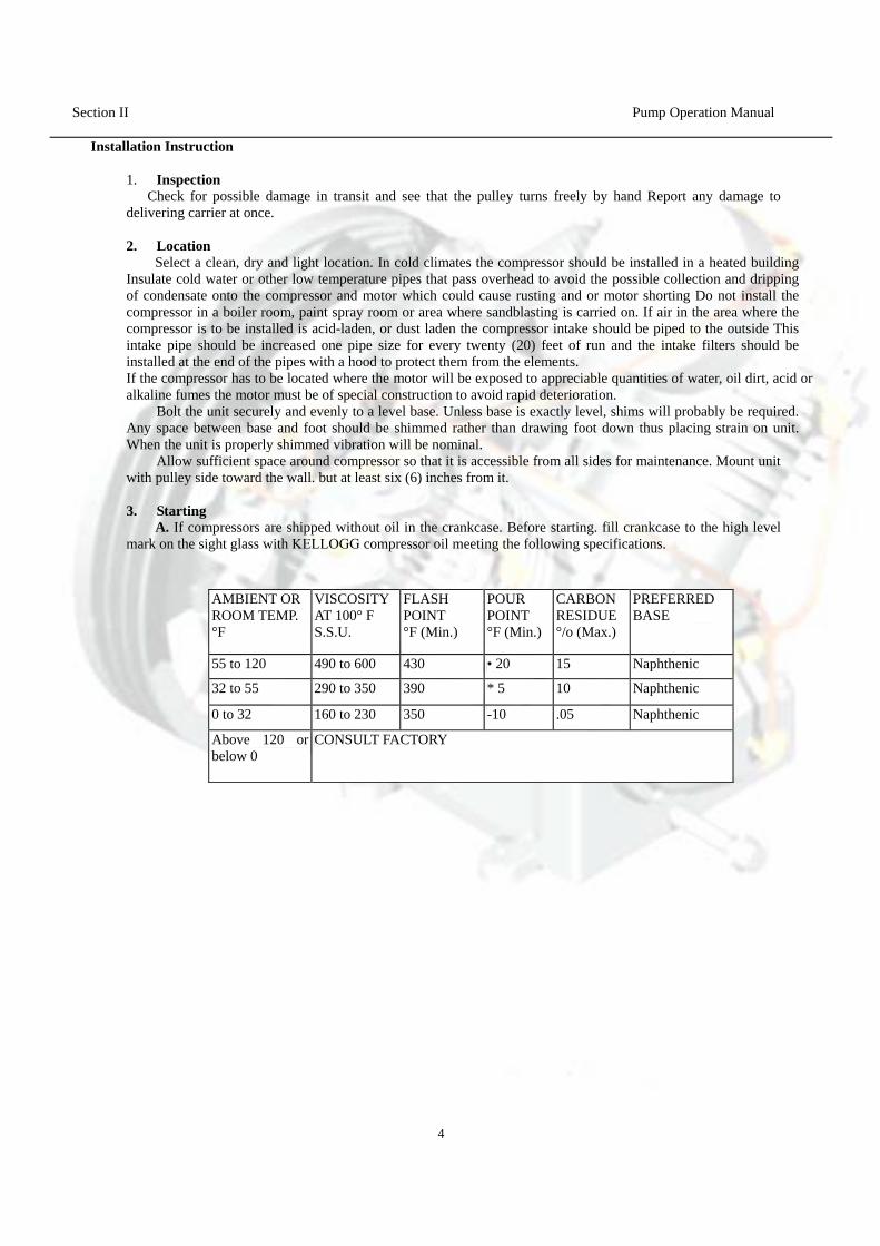
1. InspectionCheck for possible damage in transit and see that the pulley turns freely by hand Report any damage to
delivering carrier at once.
2. LocationSelect a clean, dry and light location. In cold climates the compressor should be installed in a heated building
Insulate cold water or other low temperature pipes that pass overhead to avoid the possible collection and dripping of condensate onto the compressor and motor which could cause rusting and or motor shorting Do not install the compressor in a boiler room, paint spray room or area where sandblasting is carried on. If air in the area where the compressor is to be installed is acid-laden, or dust laden the compressor intake should be piped to the outside This intake pipe should be increased one pipe size for every twenty (20) feet of run and the intake filters should be installed at the end of the pipes with a hood to protect them from the elements. If the compressor has to be located where the motor will be exposed to appreciable quantities of water, oil dirt, acid or alkaline fumes the motor must be of special construction to avoid rapid deterioration. Bolt the unit securely and evenly to a level base. Unless base is exactly level, shims will probably be required. Any space between base and foot should be shimmed rather than drawing foot down thus placing strain on unit. When the unit is properly shimmed vibration will be nominal. Allow sufficient space around compressor so that it is accessible from all sides for maintenance. Mount unit with pulley side toward the wall. but at least six (6) inches from it.
3. StartingA. If compressors are shipped without oil in the crankcase. Before starting. fill crankcase to the high level
mark on the sight glass with KELLOGG compressor oil meeting the following specifications.
AMBIENT OR ROOM TEMP. °F
VISCOSITYAT 100° F S.S.U.
FLASH POINT °F (Min.)
POUR POINT °F (Min.)
CARBON RESIDUE °/o (Max.)
PREFERRED BASE
55 to 120 490 to 600 430 • 20 15 Naphthenic
32 to 55 290 to 350 390 * 5 10 Naphthenic
0 to 32 160 to 230 350 -10 .05 Naphthenic
Above 120 or below 0
CONSULT FACTORY
Section II Pump Operation manual
5
For operation in damp or humid locations, addition of rust inhibitor is recommended. B. Turn compressor over a few revolutions by hand to make sure that everything is free and in running condition. C. Check tension of the belts (See Paragraph 6). D. Remove tools, rags and any other objects from the vicinity of the compressor. E. Never put hands on the belts of idle units. unless main power is secured. F. Note direction of arrow on flywheel and be sure direction of rotation is correct when machine is started Correct direction is counter-clockwise when standing facing the flywheel. Air should be drawn through inter-cooler onto the cylinders for maximum cooling
Section II Pump Operation Manual
6
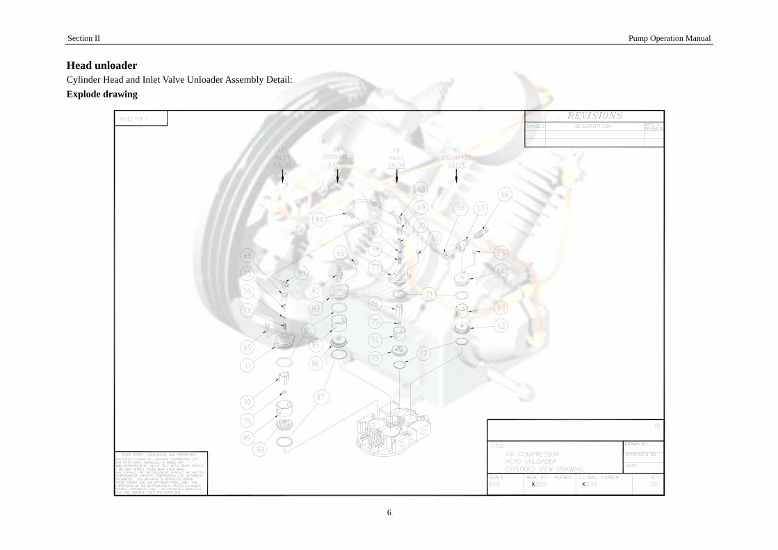
Head unloader Cylinder Head and Inlet Valve Unloader Assembly Detail: Explode drawing
Section II Pump Operation manual
7
Bom list
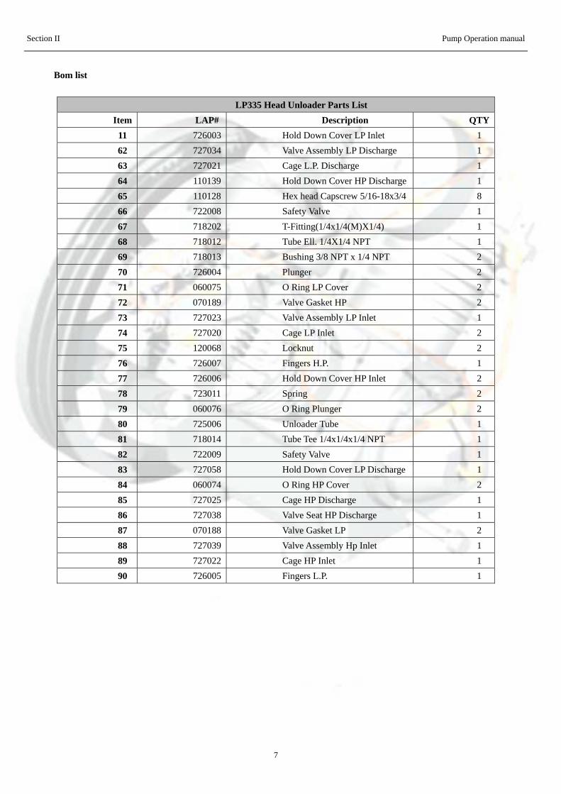
LP335 Head Unloader Parts List Item LAP# Description QTY
11 726003 Hold Down Cover LP Inlet 1 62 727034 Valve Assembly LP Discharge 1 63 727021 Cage L.P. Discharge 1 64 110139 Hold Down Cover HP Discharge 1 65 110128 Hex head Capscrew 5/16-18x3/4 8 66 722008 Safety Valve 167 718202 T-Fitting(1/4x1/4(M)X1/4) 168 718012 Tube Ell. 1/4X1/4 NPT 1 69 718013 Bushing 3/8 NPT x 1/4 NPT 2 70 726004 Plunger 271 060075 O Ring LP Cover 2 72 070189 Valve Gasket HP 273 727023 Valve Assembly LP Inlet 174 727020 Cage LP Inlet 2 75 120068 Locknut 276 726007 Fingers H.P. 177 726006 Hold Down Cover HP Inlet 2 78 723011 Spring 279 060076 O Ring Plunger 2 80 725006 Unloader Tube 181 718014 Tube Tee 1/4x1/4x1/4 NPT 1 82 722009 Safety Valve 183 727058 Hold Down Cover LP Discharge 1 84 060074 O Ring HP Cover 2 85 727025 Cage HP Discharge 1 86 727038 Valve Seat HP Discharge 1 87 070188 Valve Gasket LP 288 727039 Valve Assembly Hp Inlet 1 89 727022 Cage HP Inlet 1 90 726005 Fingers L.P. 1
Section II Pump Operation manual
8
Operation The inlet valve unloaders are designed to provide CONSTANT SPEED CONTROL by holding open the inlet valves in both cylinders. When the air supply exceeds the demand and the discharge pressure rises above the maximum required, the pilot valve (not shown) admits air at discharge pressure to a plunger in each unloader, holding the inlet valve discs off their seats. Thus the air drawn into the cylinders is freely discharged without being compressed. When the pressure has dropped to the desired minimum, the pilot valve closes, allowing the inlet valves to seat and compression to be resumed.
Safety information
DANGER
Please observe the following instructions when performing any maintenance, cleaning, repair work; when relocating the compressor plant; prior to installing and dismounting component parts, receivers, fittings and screw connections.
• Always isolate the compressor at the main switch prior to performing any maintenance work.Secure the main switch against accidental switching on! Remove the electrical fuses in order to avoidaccidents!
• Depressurize the compressor!Disconnect from the compressed air network by closing the ball valve on the compressed air outlet. Perform maintenance or servicing work. Only allow skilled and qualified welders to perform welding work on compressed air receivers! After welding work on compressed air receivers, new constructional and hydrostatic pressure tests are to be carried out.
• Prior to switching on again, check whether anyone else is working on the compressor!For your own safety, never omit a safety step! Otherwise you will risk injury from restarting, electric shock or parts which may fly off!
Important! Before do any install and maintenance work must be clean pump and parts!!
Section II Pump Operation manual
9
Installation Place seat gaskets (72 &87), valves (62,73,86 & 88) and cages (63,75,85 & 89) into head in sequence as shown. Install "O" ring (79) on plunger (70) and assemble with spring (78) into inlet hold-down cover (11 & 77) . Assemble fingers (76 & 90) and locknut (76) to complete assembly. Install hold-down cover assemblies with "O" rings (71 & 84) using cap screws (70). Tighten evenly to a torque of 10 foot lbs. Connect unloader tube (80) to tube elbow (68) and tube tee (81). Connect tubing from pilot valve to tube tee (81). Lubrication When assembling plunger, (70) and "O" ring (79) to hold-down cover (11&77), coat "O" ring with silicon grease to facilitate assembly. Service Dirt in unloader line or defective pilot valve could hold valve open allowing unloading fingers to keep inlet valves open. Sometimes tapping the pilot valve will allow pilot valve to resume normal operation. If not, remove, clean or replace. Also broken "O" ring (79) may cause erratic operation. Refer to unloader pilot operation and maintenance details.
WARNING
IMPORTANT: When ordering give MODEL and SERIAL NUMBERS of compressor.
Section II Pump Operation Manual
10
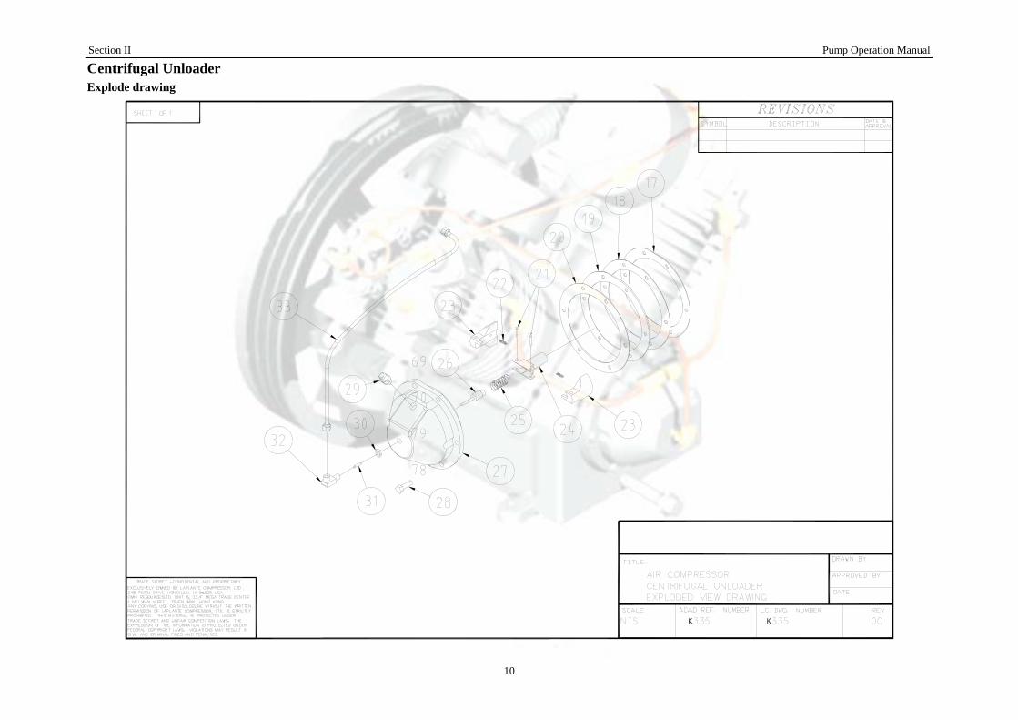
Centrifugal Unloader Explode drawing
Section II Pump Operation manual
11
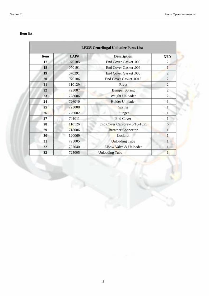
Bom list
LP335 Centrifugal Unloader Parts List
Item LAP# Description QTY17 070185 End Cover Gasket .005 2 18 070191 End Cover Gasket .006 1 19 070291 End Cover Gasket .003 2 20 070186 End Cover Gasket .0015 2 21 110129 Rivet 222 723007 Bumper Spring 223 728006 Weight Unloader 224 726010 Holder Unloader 125 723008 Spring 126 726002 Plunger 127 701011 End Cover 128 110126 End Cover Capscrew 5/16-18x1 6 29 718006 Breather Connector 130 120069 Locknut 131 725005 Unloading Tube 132 727040 Elbow Valve & Unloader 133 725005 Unloading Tube 1
Section II Pump Operation manual
12
Operation
The centrifugal unloader is designed to give "loadless" starting to the compressor units to which it is applied. When the current to the motor is interrupted or if the pump stops, for any reason, the centrifugal unloader will release the air in the aftercooler and head. When the unit resumes operation, the unloader valve closes allowing a build up of tank pressure. WARNING — When using 3 phase motors be sure of proper rotation or weight retainer assembly will work loose in a very short time. Test motor rotation without belts assembled. Correct rotation is counter-clockwise when facing flywheel side.
Safety information
DANGER
Please observe the following instructions when performing any maintenance, cleaning, repair work; when relocating the compressor plant; prior to installing and dismounting component parts, receivers, fittings and screw connections. • Always isolate the compressor at the main switch prior to performing any maintenance work. Secure the main switch against accidental switching on! Remove the electrical fuses in order to avoid accidents! • Depressurize the compressor!Disconnect from the compressed air network by closing the ball valve on the compressed air outlet. Perform maintenance or servicing work. Only allow skilled and qualified welders to perform welding work on compressed air receivers! After welding work on compressed air receivers, new constructional and hydrostatic pressure tests are to be carried out. • Prior to switching on again, check whether anyone else is working on the compressor!For your own safety, never omit a safety step! Otherwise you will risk injury from restarting, electric shock or parts which may fly off!
Important! Before do any install and maintenance work must be clean pump and parts!!
Section II Pump Operation manual
13
Installation The centrifugal unloader weight retainer assembly (21, 22, 23, 24 & 25) may be assembled to crankshaft in either of two methods. Preferred method is by mounting to crankshaft when crankshaft is removed from base during assembly of pump. The second method is used when only the centrifugal unloader is to be dismantled and only end cover (27) is removed, then centrifugal unloader weight retainer assembly (21, 22, 23, 24 & 25) may be assembled when crankshaft is in base. Assemble assembly into tapped hole in crankshaft (L. H. Threads). Apply wrench to weight retainer (5) to tighten snugly. Do not bend wings of weight retainer. Assemble end cover (27) end cover gaskets (17, 18,19 & 20) to pump base with capscrews (28). Check end play of crankshaft in accordance to pump part sheet instruction. Insert plunger (26) into valve elbow assembly (30, 31 & 32) and screw into end cover until part of valve (31) can be seen when looking into tube opening of elbow (32). Do not screw elbow into end cover too far or unloader will not operate properly. Secure valve elbow assembly in position by tightening jam nut (30). Connect unloader tube (33) to elbow in high pressure discharge hold-down cover and valve elbow (32). Connect breather tube to elbow in head and to straight connector (29) in end cover.
Lubrication When assembling unloader unit, plunger (26) and rivets (21) with good grade of machine oil.
Service Leakage of air out through the unloader valve elbow opening after the unit has been shut off for a time, is an indication of a check valve leak and should be corrected by repair or replacement.
IMPORTANT - When ordering, give MODEL and SERIAL NUMBERS of compressor.
Section II Pump Operation manual
14
Operation
Every compressor undergoes a trial run in the factory and is carefully tested and set. However, damage occurring afterwards, e.g. during transport, cannot be excluded. Therefore, the compressor should always be subjected to a trial run during commissioning and carefully monitored.
WARNING
Before start pump must be do the following job first!!!
Check power supply and ; Check oil level; top up if necessary; Check fastener and piping connection;
For 3-phase power:
Ensure no problem; start-up pump to check rolling direction, counter-clockwise is right, if not, please change 2 of 3-phase power wiring.
If all items are ok, start the pump in operating.
Section III Pump Operation Manual
1
Parts Kits
About parts kits of pump include 4 sets:
1. Overhaul Kit: Includes1 each of filer element and ring set, valve set, gasket set.2. Ring Set: Includes 1 set of piston rings.3. Valve Set: Includes 1 set of inlet valve and outlet valve.4. Gasket Set: Includes1 each of gasket.
For each pumps you can find the relevant parts kits number and describe in the explode drawings and bom list section.
Safety information
DANGER
Please observe the following instructions when performing any maintenance, cleaning, repair work; when relocating the compressor plant; prior to installing and dismounting component parts, receivers, fittings and screw connections. • Always isolate the compressor at the main switch prior to performing any maintenance work. Secure the main switch against accidental switching on! Remove the electrical fuses in order to avoid accidents! • Depressurize the compressor!Disconnect from the compressed air network by closing the ball valve on the compressed air outlet. Perform maintenance or servicing work. Only allow skilled and qualified welders to perform welding work on compressed air receivers! After welding work on compressed air receivers, new constructional and hydrostatic pressure tests are to be carried out. • Prior to switching on again, check whether anyone else is working on the compressor!For your own safety, never omit a safety step! Otherwise you will risk injury from restarting, electric shock or parts which may fly off!
Section III Pump Operation Manual
2
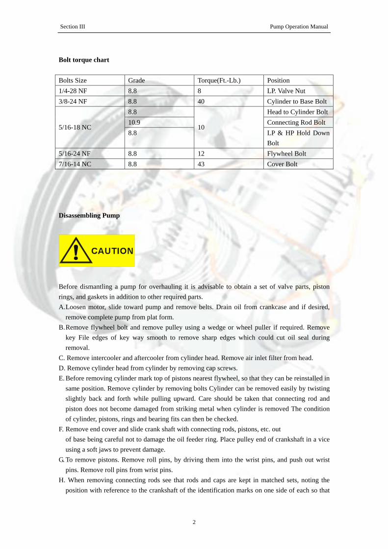
Bolt torque chart
Bolts Size Grade Torque(Ft.-Lb.) Position 1/4-28 NF 8.8 8 LP. Valve Nut 3/8-24 NF 8.8 40 Cylinder to Base Bolt
8.8 Head to Cylinder Bolt10.9 Connecting Rod Bolt
5/16-18 NC 8.8
10 LP & HP Hold Down Bolt
5/16-24 NF 8.8 12 Flywheel Bolt 7/16-14 NC 8.8 43 Cover Bolt
Disassembling Pump
Before dismantling a pump for overhauling it is advisable to obtain a set of valve parts, piston rings, and gaskets in addition to other required parts. A. Loosen motor, slide toward pump and remove belts. Drain oil from crankcase and if desired,
remove complete pump from plat form. B. Remove flywheel bolt and remove pulley using a wedge or wheel puller if required. Remove
key File edges of key way smooth to remove sharp edges which could cut oil seal during removal.
C. Remove intercooler and aftercooler from cylinder head. Remove air inlet filter from head. D. Remove cylinder head from cylinder by removing cap screws. E. Before removing cylinder mark top of pistons nearest flywheel, so that they can be reinstalled in
same position. Remove cylinder by removing bolts Cylinder can be removed easily by twisting slightly back and forth while pulling upward. Care should be taken that connecting rod and piston does not become damaged from striking metal when cylinder is removed The condition of cylinder, pistons, rings and bearing fits can then be checked.
F. Remove end cover and slide crank shaft with connecting rods, pistons, etc. out of base being careful not to damage the oil feeder ring. Place pulley end of crankshaft in a vice using a soft jaws to prevent damage.
G. To remove pistons. Remove roll pins, by driving them into the wrist pins, and push out wrist pins. Remove roll pins from wrist pins.
H. When removing connecting rods see that rods and caps are kept in matched sets, noting the position with reference to the crankshaft of the identification marks on one side of each so that
Section III Pump Operation Manual
3
the connecting rod can be replaced in the same position it originally occupied. I. Drive oil seal out of base (only if replacement is necessary) with evenly spaced blows from inside. J. To dismantle head, remove low pressure hold-down covers and high pressure hold-down covers
by removing cap screws. Lift out low pressure cages and high pressure cages. Low pressure valves and high pressure valves can be lifted out as well as the low pressure seat gasket (15. fig. 4) and high pressure seat gasket.
K. To dismantle valves, place valve in a soft jaw vise and remove center screw Valves are now free to take apart Clean all parts thoroughly. Valve plates and seats- (must be smooth and flat and can sometimes be resurfaced by rubbing on fine emery cloth held on a smooth surface.
Badly worn parts including springs, which lose tension after considerable use should be replaced.
Fitting and Reassembling
Clean all parts thoroughly before assembling. A. Crankshaft — Base
Be sure base is cleaned to remove all metal chips and dirt. Insert crankshaft and oil feeder ring only into base assemble end cover and tighten end cover bolts evenly. End cover gaskets or shims are furnished in three thicknesses and the proper combination must be selected so that crankshaft can be "spun" in the bearings without "end play". Also see that oil feeder ring turns freely within the guide lugs in the base. Then remove crankshaft.
B. Piston — Cylinder Check fit before assembling pistons to connecting rods. Pistons without rings should slide through the cylinder of their own weight and holding the skirt of the piston with the two thumbs there should be no appreciable side motion at any point of piston travel. Scored cylinders or pistons should be replaced. C. Wrist Pins should be "tap" fit by hammer. See that roll pin holes are in line.
D. Wrist Pin — Needle Bearing Fit so that piston can be "rocked" with three fingers — the thumb on one side and index and middle fingers on the other. The piston should not rock of its own weight. Drive roll pin into wrist pin when piston and wrist pin holes are in line and piston is assembled to connecting rod. If replacement of a needle bearing ever becomes necessary, be sure to press in the new bearing so that the small hole through casting lines up with oil hole in rod. Wrist pin should also be replaced.
E. Connecting Rod — Crankshaft Tap cap, when insert bearings are assembled to rod and cap to make sure bearing is making contact and tighten rod bolts with lock washers in place to prevent loosening (torque — 25 foot pounds). The combined piston and connecting rod should turn slowly on the crankshaft of their own weight if bearing adjustment incorrect. It will be noted that ends of the inserts extend slightly above the parting line of the rod and cap and under no circumstance should these ends of the inserts be filed.
Section III Pump Operation Manual
4
F. Reinstall crankshaft with pistons and connecting rods attached being careful not to damage oil feeder ring when fitting within base lugs and being sure there are no burrs or dirt on the pulley end of the crankshaft that might cut the oil seal.
G. If oil seal is to be replaced slide over the crankshaft and press into place in the base, the lip or seal side toward the crankcase. Do not hammer directly on the seal.
H. Replace valve parts in sequence indicated in explode drawing being careful not to force any parts together when tightening this center screw (11).and locknut (Torque — 28 foot — pounds). After assembly .depress valve plate to insure that the valve works freely.
I. Head Assembly Install seat gaskets valve assemblies Cages, "O" rings, Hold down covers and cap-screws. Tighten cap screws evenly so as not to break corners of hold down covers (Torque — 10 foot — pounds), Assemble head to cylinder (Torque -10 foot - pounds).
J. Install key and pulley after cylinder head, intercooler and after-cooler are connected. K. Turn pulley over by hand several times to insure that no interference of any kind exists. L. "Running in" for a few hours without the head assembly is recommended if a pump has been
completely overhauled — especially if new pistons and/or cylinders have been installed.
Valves Valves are generally considered to be maintenance items and require care by the user. They are the most important part of the compressor and the importance of proper care and maintenance cannot be over-emphasized. All valves should be removed from the cylinder head at the end of the first two or three months of operation and examined for cleanliness and carbon formation. Clean with safety solvent and blow off with compressed air. Depending on what is found at this inspection, the next inspection should not be more than 4 to 6 months later. These 2 inspections will guide you in scheduling periodic cleaning times which will pay off many times over in providing trouble free service and reduced down time.
Troubleshooting
1. Slow Pumping Or Insufficient Pressure Can Be Caused By
A Clogged inlet filter — (Disassemble and clean thoroughly.) B Leaks in air lines, valves, fittings, etc. (Locate using soapy water if necessary: replace or tighten
threaded parts.) C Compressor too small for equipment being operated — (Check air requirements and add to
compressor capacity — consult dealer.) D Leaking head valves - (Remove hold-down covers and remove valves for examination. Repair
or replace faulty valves.) Valves can be removed from head by tapping valve screw with hammer handle or piece of wood, to loosen valve from head, before lifting valve. Clean all parts thoroughly. Valves and seats must be flat and smooth and sometimes can be resurfaced by rubbing on fine emery cloth held on a smooth flat surface. Badly worn parts, including springs which lose tension after considerable use should be replaced Reassemble
Section III Pump Operation Manual
5
valve parts in sequence indicated in explode drawing. Examine valve gaskets carefully and replace if doubtful of condition. Be careful that nothing falls into the cylinder that could get caught between top of piston and cylinder head. Before reassembling valve look into cylinder through valve opening while turning flywheel by hand.
2. Excessive Oil Consumption"Oil Pumping" usually results from using the wrong type or an inferior grade of oil. Replacing worn or stuck piston rings will help correct this condition but contrary to popular belief, worn rings do not affect pumping efficiency appreciably. Piston rings can be replaced by removing cylinder while the heads are off. Remove rings and clean grooves in piston. The low pressure oil ring provided is of the latest design and is the same as furnished on the new automobile engines. It is of three-piece construction with two chrome-plated rails and an expander ring. Some new units may pump a slight amount of oil for a period of time but as the chrome-plated rails seat to the cylinder walls this will gradually diminish. Should excessive oil consumption continue, the cylinders should be checked for scoring and the oil ring checked for proper assembly. The two ends of the expander rings are colored with paint for identification and when properly assembled should be butted, not overlapped. The high pressure oil ring is of the one piece construction. A coating of clean oil should be placed on the rings and the inside of the cylinders for ease of assembly and to minimize possibility of scoring cylinder. See Paragraph 16 for reassembly procedure.
3. Noisy Operation Can Be Caused ByA. Loose parts — external — (Tighten loose bolts, particularly the flywheel pulley to the
crankshaft.) B. Foreign matter such as carbon, metal chips, etc. on pistons striking head at top of stroke
(Remove head and clean). C. Piston extending above cylinder at top of stroke and hitting head. (Remove cylinder and add
base gasket, not upper cylinder gasket.) D. End play in crankshaft — (Remove end cover, take out one end cover gasket or shim and
replace). Do not remove too many shims or binding may result, see Paragraph under fitting and reassembling.
E. Loose valves — Hex head cap screws are not tight enough. (Tighten screws )
Screws should be tightened snugly but not too tight as hold-down cover corners could be broken. Screws should be tightened evenly keeping covers parallel with cylinder head. Screws have nylon insert in threads and are of self-locking construction. They will not loosen from vibration and can be removed and retightened several times without losing their holding ability. F. Loose or worn parts — Internal, e.g. pistons, connecting rods, wrist pins, valves — (Pump
Section III Pump Operation Manual
6
should be overhauled — preferably in distributors service department or factory. Loose rod bolts can be tightened after removing crankshaft, but if bearings are worn or scored, new insert bearings must be installed.) 4. Oil Leak
At base or end cover gasket — (Disassemble at point of leak, shellac or perma-gasket on bothsides and reassemble. Maintain correct oil level).
5. VibrationCharacteristic of all reciprocating machines. can be held to a minimum by keeping the compressor securely fastened to a solid level foundation, maintaining proper belt alignment and keeping nuts and bolts tight.
6. OverheatingCompression of air generates heat, much of which is dissipated as air passes over the intercooler and/or aftercooler . Overheating can be caused by: A. Pump running backwards — (Reverse direction.) Proper rotation is counterclockwise facing flywheel. B. One or more head valves failing to seat properly — (Remove hold-down cover, valve cage, and valve. Clean, reseat or replace valves.) C. Blown cylinder head gasket — (Replace after cleaning all traces of old gasket from head and cylinder.) . D. Restriction in head, intercooler or check valve if used. — (Remove and clean.) E. Lack of oil — (Check oil level, if necessary, remove side plate to see that oil feeder ring is free to turn.) F. Dirt in intercooler fins or cylinder fins - (Blow out with air.) G. Poor ventilation and high room temperature (If compressor cannot be moved, check possibility of piping intake to cooler location.)
7. Compressor Has No Or Insufficient OutputA. Suction filter soiled-( Clean suction filter) B. Suction and pressure valves worn or defective-( Replace valves) C. Vent (unloading) valve does not close-( Check whether the vent (unloading) valve closes when the compressor is running; overhaul or replace valve, if necessary)
8. Safety Valve Of The First Stage Blows OffA. Suction and pressure valves of the second stage defective or worn-( Replace valves) B. Seal between valve and cylinder head defective-( Replace seal)
9. Oil Foam in The CrankcaseA. Last stage piston worn-( Operate compressor with final stage valve head removed. If oil
collects at rim of cylinder, piston clearance ok. If oil flows continuously out of cylinder, replace piston and liner)
B. Last stage outlet valve defective-( Replace) 10. Oil out of from the breather
Section III Pump Operation Manual
7
Compressor piston jammed-(Replace pistons and cylinders)
Maintenance
To obtain reliable and satisfactory service, this unit requires a consistent preventive maintenance program. Maintenance schedule pages are included in the back of this manual to aid in keeping the proper records.
General 1. Check your compressor regularly!2. Check entire system for air leakage around fittings, connections, and gaskets, using soap
solution.3. Remove dust or oil soiling.4. Check fastener tightness by using torque wrench to the corresponding values within this guide.
Safety information
DANGER
Please observe the following instructions when performing any maintenance, cleaning, repair work; when relocating the compressor plant; prior to installing and dismounting component parts, receivers, fittings and screw connections. • Always isolate the compressor at the main switch prior to per
forming any maintenance work.Secure the main switch against accidental switching on! Remove the electrical fuses in order to avoid accidents! • Depressurize the compressor!Disconnect from the compressed air network by closing the ball valve on the compressed air outlet. Perform maintenance or servicing work. Only allow skilled and qualified welders to perform welding work on compressed air receivers! After welding work on compressed air receivers, new constructional and hydrostatic pressure tests
are to be carried out. •Prior to switching on again, check whether anyone else is working on the compressor!For your own safety, never omit a safety step! Otherwise you will risk injury from restarting, electric shock or parts which may fly off!
Section III Pump Operation Manual
8
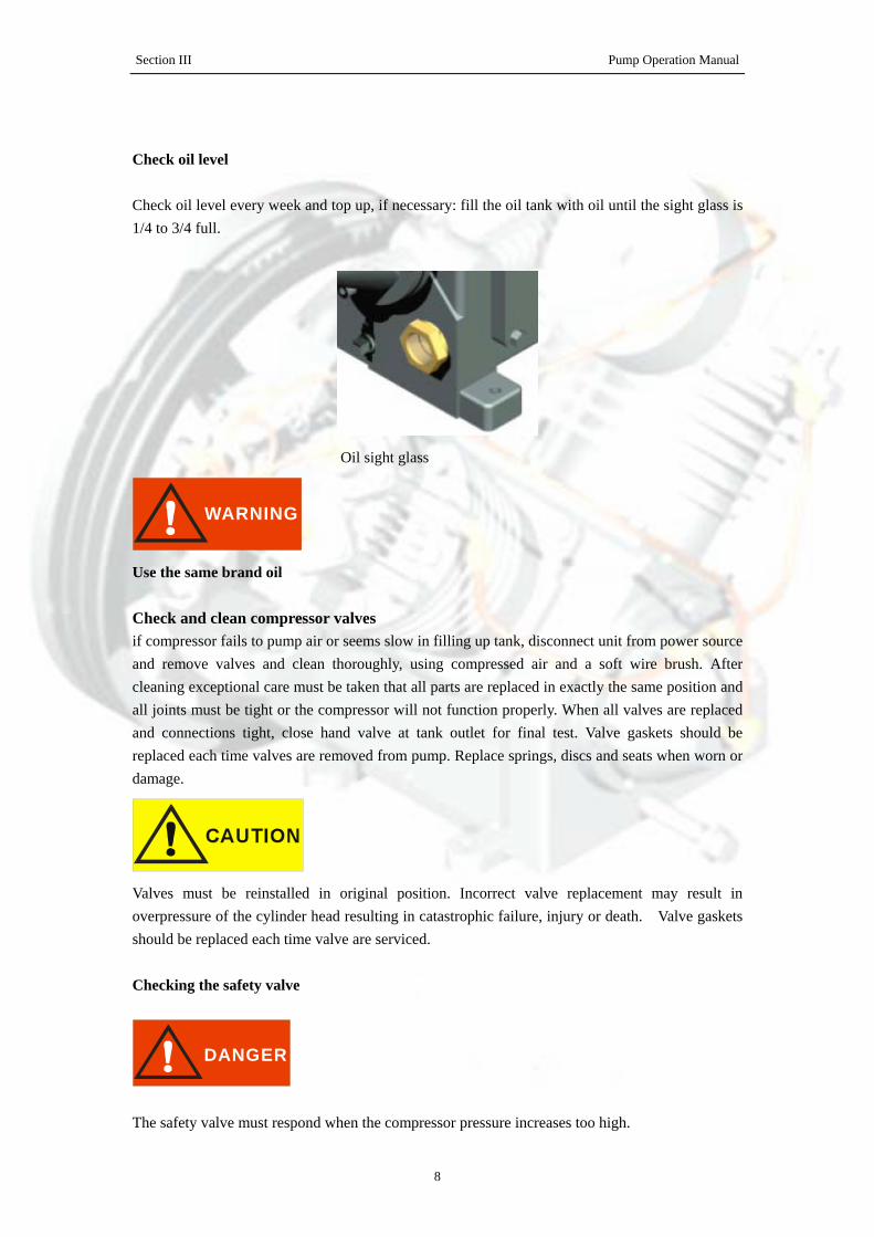
Check oil level
Check oil level every week and top up, if necessary: fill the oil tank with oil until the sight glass is 1/4 to 3/4 full.
Oil sight glass
WARNING
Use the same brand oil
Check and clean compressor valves if compressor fails to pump air or seems slow in filling up tank, disconnect unit from power source and remove valves and clean thoroughly, using compressed air and a soft wire brush. After cleaning exceptional care must be taken that all parts are replaced in exactly the same position and all joints must be tight or the compressor will not function properly. When all valves are replaced and connections tight, close hand valve at tank outlet for final test. Valve gaskets should be replaced each time valves are removed from pump. Replace springs, discs and seats when worn or damage.
Valves must be reinstalled in original position. Incorrect valve replacement may result in overpressure of the cylinder head resulting in catastrophic failure, injury or death. Valve gaskets should be replaced each time valve are serviced.
Checking the safety valve
DANGER
The safety valve must respond when the compressor pressure increases too high.
Section III Pump Operation Manual
9
The inter stage pressure relief valve is provided to protect against inter stage over pressure and is factory set for maximum pressure of 75 PSIG. If the pressure relief valve pops open, it indicates trouble. Shut down the unit immediately and determine and correct the malfunction. Inspect the head valves. Serious damage can result if not corrected and can lead to complete destruction of the unit. Tampering with the inter stage pressure relief valve, or plugging the opening destroys the protection provided and voids all warranty.
The valve must be able to blow off the entire delivery quantity of the compressor. As it is rarely or never operated, it is of utmost importance for the safety of the compressor that the valve is regularly checked. Check the valve once a year or after 2000 operating hours.
This is the only maintenance work which has to be performed while the compressor is running. Make sure that all safety devices are correctly installed! Never perform this work with the safety device removed! Danger of injury or death!
WARNING
Do not readjust!! Test safety valve on compressor: A ring is located at the free end of the safety valve. Pull the ring by hand. Never remove the lead seal at the head of the valve! If you now pull the ring further, the safety valve should blow off increasingly more air. If the valve blows off correctly, dropt hand tight in its seating and complete the check. • If the valve does not blow off although you have pull the ring up to the end of the stud, it isdefective. Please have a new safety valve fitted by KELLOGG Service. Test the valve as described in section "Testing safety valve on compressor". Compressor Oil
General Compressors are factory filled with KELLOGG hydrocarbon based recip lubricant. This is an ISO non-detergent industrial lubricant with rust and oxidation inhibitors specially formulated for reciprocating compressors. It is recommended this compressor be maintained using this oil for ambient temperature above 32 F degreed. KELLOGG synthetic is a premium grade diester based synthetic lubricant providing excellent performance in high temperature applications.
Do not mix oil types, weights or brands.
Section III Pump Operation Manual
10
Normal break-in period of KELLOGG air compressors is 25 hours. for the first 500 hours of compressor operation, a careful and regular check of the oil level should be made. Maintain oil level at the full time. Change To Synthetic Lubricant If changing to synthetic lubricant, the following steps must be completed. Compressor must run for a 25 hour break-in period using KELLOGG ISO 100 oil. Thoroughly drain existing oil from crankcase. Fill crankcase with a full charge of synthetic lubricant. Run compressor for 200 hours. Stop compressor and thoroughly drain the synthetic lubricant. Add a full charge of synthetic lubricant. Compressor now ready to run for extended period before next lubricant change made. Maintain oil level at the full line. Lubricant Frequency Of Oil Change Change oil every 3000 operating hours whichever comes first. For constant run applications in daily use or units subjected to extremely heavy use change oil monthly.
Oil Recommendation
Any Approved Oil Which Is Equal To Those Specified May Be Used
Ambient Or Room Temperature 55° F To 120° F
AMOCO SHELL MOBIL TEXACO CHEVRON GULF EXXON
#51 Tellus Oil 41 Rotella Oil 30
Del vac 1230 DTE Heavy
Regal ER&O EP68X Paramount 58 Teresstic 100
Ambient Or Room Temperature 32° F TO 55° F
AMOCO SHELL MOBIL TEXACO CHEVRON GULF EXXON
#31 Tellus Oil 33 Rotella Oil 20-20W
Delvac 1220 DTE Heavy Med.
Regal CR & O EP55X Paramount 49 Teresstic 68
Section III Pump Operation Manual
11
Ambient Or Room Temperature 0° F TO 32° F
AMOCO SHELL MOBIL TEXACO CHEVRON GULF EXXON
#21 Tellus Oil 25 Rotella Oil 10W
Delvac 1210 DTE Medium
Cetus Oil EP45X Paramount 65 Teresstic 32
Suction Filter
Regularly and carefully maintain the suction filter approx. every 500 operating hours, depending on the degree of soiling of the air taken in. Soiled suction filters can cause high oil consumption and reduced delivery quantity! If the installation site is heavily contaminated with dust, provide a dry air filter with paper cartridge. If the ambient air is heavily contaminated, we recommend using dry air filters.
All compressors are available with a common air filter with under pressure display for all cylinders.
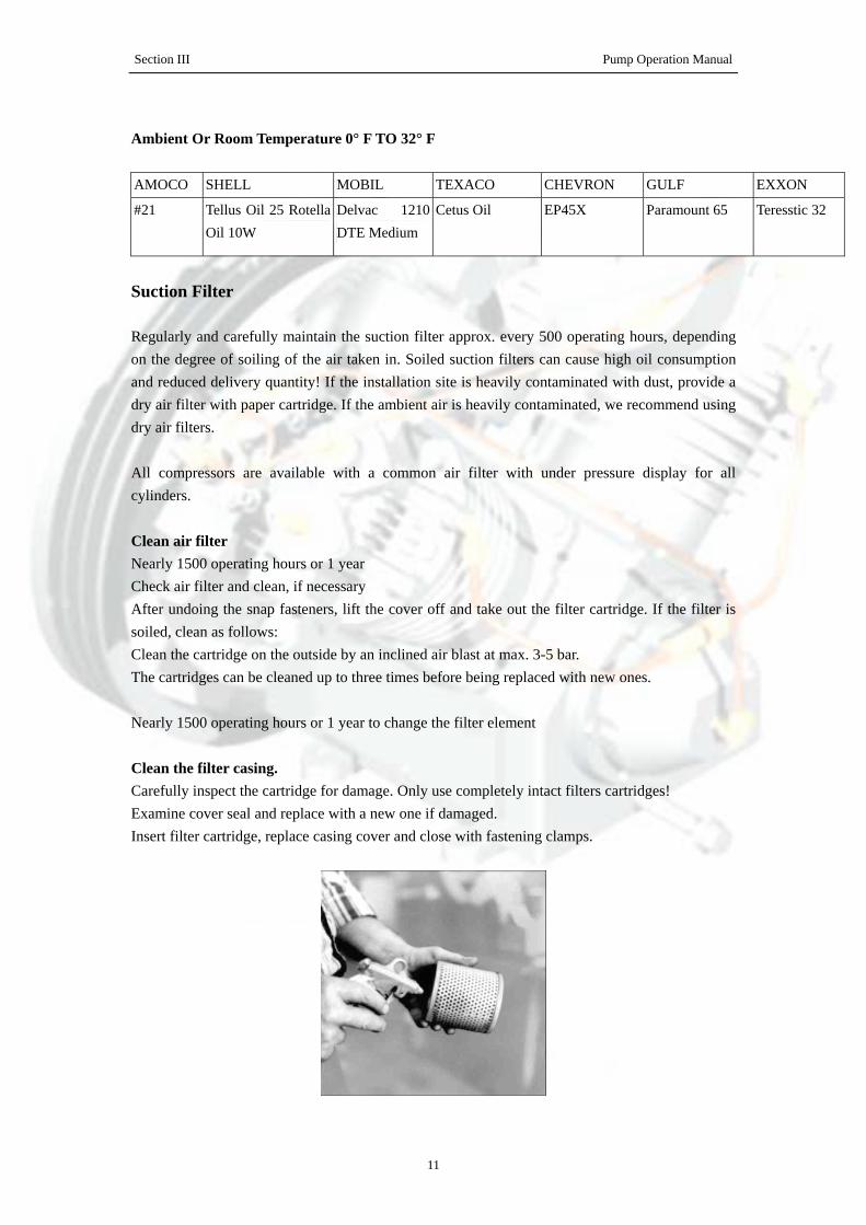
Clean air filter Nearly 1500 operating hours or 1 year Check air filter and clean, if necessary After undoing the snap fasteners, lift the cover off and take out the filter cartridge. If the filter is soiled, clean as follows: Clean the cartridge on the outside by an inclined air blast at max. 3-5 bar. The cartridges can be cleaned up to three times before being replaced with new ones.
Nearly 1500 operating hours or 1 year to change the filter element
Clean the filter casing. Carefully inspect the cartridge for damage. Only use completely intact filters cartridges! Examine cover seal and replace with a new one if damaged. Insert filter cartridge, replace casing cover and close with fastening clamps.
Section III Pump Operation Manual
12
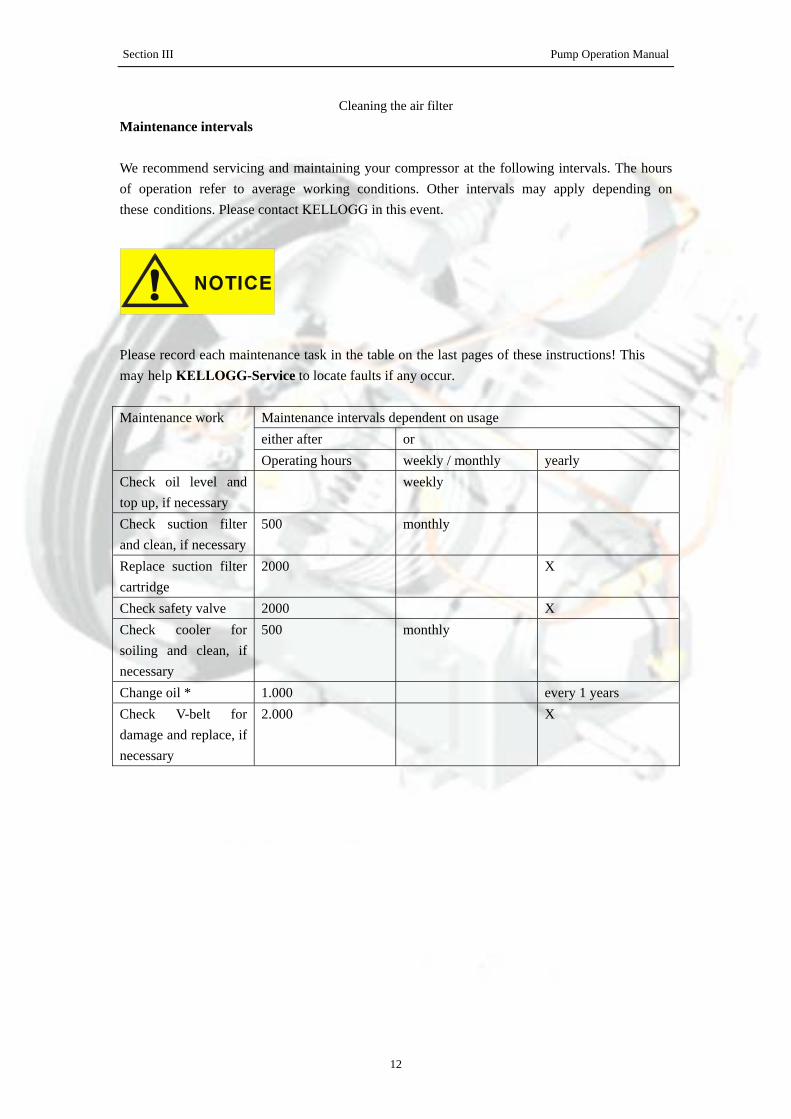
Cleaning the air filter Maintenance intervals
We recommend servicing and maintaining your compressor at the following intervals. The hours of operation refer to average working conditions. Other intervals may apply depending on these conditions. Please contact KELLOGG in this event.
Please record each maintenance task in the table on the last pages of these instructions! This may help KELLOGG-Service to locate faults if any occur.
Maintenance intervals dependent on usage either after or
Maintenance work
Operating hours weekly / monthly yearly Check oil level and top up, if necessary
weekly
Check suction filter and clean, if necessary
500 monthly
Replace suction filter cartridge
2000 X
Check safety valve 2000 X Check cooler for soiling and clean, if necessary
500 monthly
Change oil * 1.000 every 1 years Check V-belt for damage and replace, if necessary
2.000 X
Section III Pump Operation Manual
13
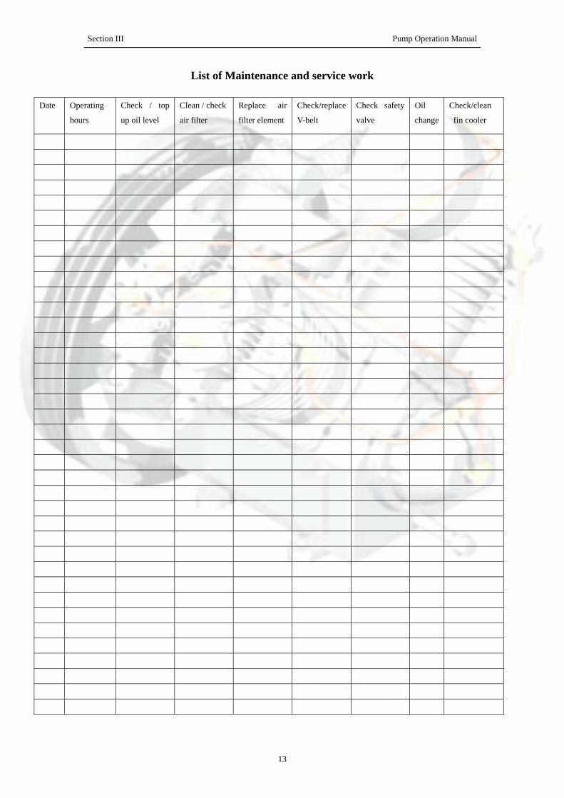
List of Maintenance and service work
Date Operating
hours
Check / top
up oil level
Clean / check
air filter
Replace air
filter element
Check/replace
V-belt
Check safety
valve
Oil
change
Check/clean
fin cooler

Section III Pump Operation Manual
14
Date Operating
hours
Check / top
up oil level
Clean / check
air filter
Replace air
filter element
Check/replace
V-belt
Check safety
valve
Oil
change
Check/clean
fin cooler

Section III Pump Operation Manual
15
Date Operating
hours
Check / top
up oil level
Clean / check
air filter
Replace air
filter element
Check/replace
V-belt
Check safety
valve
Oil
change
Check/clean
fin cooler
Section III Pump Operation Manual
16
Date Operating
hours
Check / top
up oil level
Clean / check
air filter
Replace air
filter element
Check/replace
V-belt
Check safety
valve
Oil
change
Check/clean
fin cooler

Section III Pump Operation Manual
17
Date Operating
hours
Check / top
up oil level
Clean / check
air filter
Replace air
filter element
Check/replace
V-belt
Check safety
valve
Oil
change
Check/clean
fin cooler