Inducing Phase Crystallinity in Block Copolymers of ...€¦ · Inducing Phase Crystallinity in...
16
polymers Article Inducing β Phase Crystallinity in Block Copolymers of Vinylidene Fluoride with Methyl Methacrylate or Styrene Nahal Golzari 1 , Jörg Adams 2 and Sabine Beuermann 1, * 1 Institute of Technical Chemistry, Clausthal University of Technology, Arnold-Sommerfeld-Strasse 4, 38678 Clausthal-Zellerfeld, Germany; [email protected] 2 Institute of Physical Chemistry, Clausthal University of Technology, Arnold-Sommerfeld-Strasse 4, 38678 Clausthal-Zellerfeld, Germany; [email protected] * Correspondence: [email protected]; Tel.: +49-532-372036 Received: 20 June 2017; Accepted: 20 July 2017; Published: 26 July 2017 Abstract: Block copolymers of poly(vinylidene fluoride) (PVDF) with either styrene or methyl methacrylate (MMA) were synthesized and analyzed with respect to the type of the crystalline phase occurring. PVDF with iodine end groups (PVDF-I) was prepared by iodine transfer polymerization either in solution with supercritical CO 2 or in emulsion. To activate all iodine end groups Mn 2 (CO) 10 is employed. Upon UV irradiation Mn(CO) 5 radicals are obtained, which abstract iodine from PVDF-I generating PVDF radicals. Subsequent polymerization with styrene or methyl methacrylate (MMA) yields block copolymers. Size exclusion chromatography and NMR results prove that the entire PVDF-I is converted. XRD, FT-IR, and differential scanning calorimetry (DSC) analyses allow for the identification of crystal phase transformation. It is clearly shown that the original α crystalline phase of PVDF-I is changed to the β crystalline phase in case of the block copolymers. For ratios of the VDF block length to the MMA block length ranging from 1.4 to 5 only β phase material was detected. Keywords: fluoropolymers; vinylidene fluoride; block copolymers; crystallization; phase separation 1. Introduction Most hydrofluorocarbon polymers show extraordinary thermal stability, chemical inertness, and weatherability, as well as being stable against various types of radiation. Large scale applications encompass, e.g., coatings, membranes, tubes, and piping equipment [1,2] Poly(vinylidene fluoride) (PVDF) is special, because additionally it shows ferro-, piezo-, and pyroelectric properties [3–10]. These electroactive properties are associated with the all trans conformation β crystalline phase of PVDF. However, the semi-crystalline polymer forms not only β phase material, but four more polymorphs (α, γ, δ, and ε phase) which are known [11,12]. The α polymorph is the most readily available phase. Several processes were reported to obtain β phase material, such as ultrafast cooling, melting under high pressure, mechanical stretching of the α polymorph, and blending with poly(methyl methacrylate) (PMMA), BaTiO 3 or palladium. An excellent overview on the various phases of PVDF and applications as electroactive materials is presented in reference [13]. In addition to the homopolymer of vinylidene fluoride (VDF), in binary and ternary copolymers of VDF with trifluoroethylene and chlorotrifluoroethylene β phase formation is found [3,14,15]. Due to higher sterical hindrance compared to VDF homopolymers the formation of the all trans β phase is preferred [13]. Frequently, blends of PVDF and PMMA are considered for β phase formation [16] due to favorable interactions between the highly electronegative F atoms in PVDF and the carbonyl groups of PMMA. Moreover, steric reasons are supposed to favor the trans conformation of both polymers and may lead Polymers 2017, 9, 306; doi:10.3390/polym9080306 www.mdpi.com/journal/polymers
Transcript of Inducing Phase Crystallinity in Block Copolymers of ...€¦ · Inducing Phase Crystallinity in...
polymers
Article
Inducing β Phase Crystallinity in Block Copolymersof Vinylidene Fluoride with Methyl Methacrylateor Styrene
Nahal Golzari 1, Jörg Adams 2 and Sabine Beuermann 1,*1 Institute of Technical Chemistry, Clausthal University of Technology, Arnold-Sommerfeld-Strasse 4,
38678 Clausthal-Zellerfeld, Germany; [email protected] Institute of Physical Chemistry, Clausthal University of Technology, Arnold-Sommerfeld-Strasse 4,
38678 Clausthal-Zellerfeld, Germany; [email protected]* Correspondence: [email protected]; Tel.: +49-532-372036
Received: 20 June 2017; Accepted: 20 July 2017; Published: 26 July 2017
Abstract: Block copolymers of poly(vinylidene fluoride) (PVDF) with either styrene or methylmethacrylate (MMA) were synthesized and analyzed with respect to the type of the crystalline phaseoccurring. PVDF with iodine end groups (PVDF-I) was prepared by iodine transfer polymerizationeither in solution with supercritical CO2 or in emulsion. To activate all iodine end groups Mn2(CO)10
is employed. Upon UV irradiation Mn(CO)5 radicals are obtained, which abstract iodine from PVDF-Igenerating PVDF radicals. Subsequent polymerization with styrene or methyl methacrylate (MMA)yields block copolymers. Size exclusion chromatography and NMR results prove that the entirePVDF-I is converted. XRD, FT-IR, and differential scanning calorimetry (DSC) analyses allow for theidentification of crystal phase transformation. It is clearly shown that the original α crystalline phaseof PVDF-I is changed to the β crystalline phase in case of the block copolymers. For ratios of the VDFblock length to the MMA block length ranging from 1.4 to 5 only β phase material was detected.
Keywords: fluoropolymers; vinylidene fluoride; block copolymers; crystallization; phase separation
1. Introduction
Most hydrofluorocarbon polymers show extraordinary thermal stability, chemical inertness, andweatherability, as well as being stable against various types of radiation. Large scale applicationsencompass, e.g., coatings, membranes, tubes, and piping equipment [1,2] Poly(vinylidene fluoride)(PVDF) is special, because additionally it shows ferro-, piezo-, and pyroelectric properties [3–10].These electroactive properties are associated with the all trans conformation β crystalline phaseof PVDF. However, the semi-crystalline polymer forms not only β phase material, but four morepolymorphs (α, γ, δ, and ε phase) which are known [11,12].
The α polymorph is the most readily available phase. Several processes were reported to obtainβ phase material, such as ultrafast cooling, melting under high pressure, mechanical stretching ofthe α polymorph, and blending with poly(methyl methacrylate) (PMMA), BaTiO3 or palladium.An excellent overview on the various phases of PVDF and applications as electroactive materials ispresented in reference [13]. In addition to the homopolymer of vinylidene fluoride (VDF), in binaryand ternary copolymers of VDF with trifluoroethylene and chlorotrifluoroethylene β phase formationis found [3,14,15]. Due to higher sterical hindrance compared to VDF homopolymers the formation ofthe all trans β phase is preferred [13].
Frequently, blends of PVDF and PMMA are considered for β phase formation [16] due to favorableinteractions between the highly electronegative F atoms in PVDF and the carbonyl groups of PMMA.Moreover, steric reasons are supposed to favor the trans conformation of both polymers and may lead
Polymers 2017, 9, 306; doi:10.3390/polym9080306 www.mdpi.com/journal/polymers

Polymers 2017, 9, 306 2 of 16
to a chain extension and consequently β crystallinity is promoted [16]. In addition, the influence of theglass transition temperature, Tg, on the relative growth rates of α and β spherulites is discussed [16].Depending on polymer molecular weights and the ratio of both polymers in the blend, phase separationmay occur. If phase separation in polymer blends induces β phase crystallinity of the PVDF domains,it appears particularly interesting to consider block copolymers consisting of one PVDF block. Again,phase separation is expected to occur and β phase crystallinity should occur.
So far the number of reports on PVDF block copolymers is still rather small. Reversible deactivationtransfer polymerizations frequently used for block copolymer synthesis of styrene and many(meth)acrylate monomers are difficult to be performed with VDF, mainly due to the highly reactiveprimary propagating radical. Methods involving degenerative chain transfer constitute an exceptionfrom the above said. Iodine transfer polymerizations (ITP) [17–20], the use of xanthates [21–24] orreversible addition fragmentation transfer (RAFT) polymerizations [25,26] allow for good control ofmolecular weights, result in low dispersities, and may yield block copolymers.
Generally, in ITP perfluorinated alkyl iodides such as C6F13I or C6F12I2 are used as chaintransfer agents [19,20]. Due to the rather low bond energy between iodine and the propagatingchain, the transfer reaction of iodine is reversible. Regular head to tail addition leads to –(CF2–CH2)–motifs in the polymer chain. Further, tail to tail, tail to head, and head to head additions play animportant role in VDF polymerizations leading to –CF2–CH2–CH2–CF2– and –CH2–CF2–CF2–CH2–sequences in the polymer chains as well as –CH2–CF2–I and –CF2–CH2–I end groups as identifiedby NMR spectroscopy. –CH2–CF2–I is at least 25 times more active than –CF2–CH2–I [27]. As aconsequence, the fraction of inactive –CF2–CH2–I chain ends increases with conversion. Previously,the active species, –CH2–CF2–I, was used for follow-up reactions [28–30]. In all cases, only the polymerwith active end groups was used.
Asandei and coworkers reported a synthetic strategy using Mn2(CO)10 for activation of bothiodine polymer end groups, consequently allowing for an efficient transformation of all polymerchains [31–33]. Since the linkage between two Mn atoms is weak (20–40 kJ) [34,35], visible light allowsfor the production of two •Mn(CO)5 metalloradicals with good quantum efficiency [36]. •Mn(CO)5
radicals being very good halide abstractors irreversibly activate both iodine end groups originatingfrom ITP and Mn(CO)5–I is formed [31]. Both radicals obtained (–CF2
• and –CH2•) may react with an
added monomer to initiate a free radical polymerization leading to block copolymers where PVDF-Iserves as a macroinitiator.
A different synthetic strategy is the preparation of block copolymers via functional benzoylperoxide initiated polymerization of VDF and subsequent synthesis of the second block using atomtransfer radical polymerization or ring opening polymerization [37–39]. For example, the resultingblock copolymers with the second block being poly(butyl methacrylate) showed β phase crystallinityof the PVDF block with a molecular weight of around 15,000 g·mol−1 and a PVDF molar content ofaround 0.5.
Due to the above mentioned favorable interactions and the associated miscibility of PMMAand PVDF, in this contribution the synthesis of block copolymers of VDF with MMA is reported.In addition, some copolymers with styrene as the second monomer were prepared. Firstly, PVDF-Iwas synthesized by ITP in supercritical carbon dioxide as solvent [40,41] or in emulsion [42]. Then,with PVDF-I as macroinitiator Mn2(CO)10-photomediated free radical polymerization with MMAor styrene were carried out to yield well-defined block copolymers. The molecular weight of theinitial PVDF macroinitiator and the ratio of the block lengths was varied. Atomic Force Microscopy(AFM) of thin films is considered to identify phase separation of both polymer blocks. In order toidentify whether the PVDF domains are crystalline and to analyze which type of crystalline phase isdetermined, Fourier transform infrared spectroscopy (FTIR), X-ray powder diffraction (XRD), anddifferential scanning calorimetry (DSC) were used.
Polymers 2017, 9, 306 3 of 16
2. Methods and Materials
2.1. Materials
Vinylidene fluoride (VDF, Dyneon GmbH, Burgkirchen a.d.Alz, Germany, 99.5%), styrene(S, Sigma-Aldrich, Taufkirchen, Germany, 99.5%), methyl methacrylate (MMA, Sigma-Aldrich,Taufkirchen, Germany, 99%), di-tert-butylperoxide (DTBP, Merck, Darmstadt, Germany, 98%),1-iodoperfluorohexane (ABCR, Karlsruhe, Germany, 99%), 1,4-diiodooctafluorobutane (DyneonGmbH, Burgkirchen a.d.Alz, Germany), dimanganese decacarbonyl (Sigma-Aldrich, Taufkirchen,Germany, 98%), methanol (95%), hydrochloric acid (37%), N,N-dimethyl acetamide (DMAc, Acros,Geel, Belgium, 99%), ammonium 4,8-dioxa-3H-perfluorononanoate (Dyneon, GmbH, Burgkirchena.d.Alz, Germany), ammonium peroxydisulfate (Fluka, Honeywell, Hannover, Germany, ≥98.0%),carbon dioxide (Air Liquide, Paris, France, 99.8%), N,N-dimethylformamide-d7 (Deutero GmbH,Kastellaun, Germany, 99.5%), and acetone-d6 (Deutero GmbH, Kastellaun, Germany, 99.8%) were usedas received.
2.2. Characterization
To characterize the polymers, the following techniques and equipment were used. Size-exclusionchromatography (SEC) measurements were carried out at a column temperature of 45 ◦C usingDMAc, which contains 0.1% LiBr as eluent. The SEC set-up consists of an Agilent 1200 isocraticpump, an Agilent 1200 refractive index detector, and four PSS GRAM columns (Guard, 100 Å, 3000 Å,and 3000 Å) from Polymer Standard Service (PSS). Measurements were carried out at a flow rate of1 mL·min−1. Polystyrene standards (PSS) were used for calibration. For FT-IR measurements a Vertex70 Bruker spectrometer (Bruker Optik GmbH, Bremen, Germany) equipped with a globar source and aphotoacoustic cell (PA301) was used. Spectra were measured with a resolution of 4 cm−1. 1H and 19FNMR spectra of the polymers were recorded on a Bruker AVANCE 400 MHz spectrometer at roomtemperature. Acetone-d6 and also N,N-dimethylformamide-d7 were used as solvents. To characterizethe phase separation of the copolymers, thin polymer films were prepared either by casting a solutiondirectly onto clean mica or by spin coating onto the same substrate (5 mg polymer in 1 mL DMAc,spin-coater WS-650MZ, Laurell, North Wales, PA, USA). These films were analyzed with an AFM(extended multimode, NanoScope IIIa controller, Veeco/Digital Instruments, Plainview, NY, USA)operating in tapping mode at room temperature in air. To selectively etch the PMMA or PS blocks whilekeeping the PVDF intact, air-plasma generated in a RF plasma cleaner (PDC-32G, Harrick-Plasma,Ithaca, NY, USA) was used for up to 60 s. This technique has been used successfully to contrast PS inPMMA-PS block copolymers [43]. XRD analyses at KIT were conducted by a STADI MP diffractometer(STOE, Darmstadt, Germany) with Ge-monochromatized Cu–Kα radiation (λ = 1.54060 Å). The XRDmeasurements at TUC were conducted with Cu–Kα (graphite monochromator) as well. A Bruker AXSD8 Discover diffractometer was used, equipped with a General Area Diffraction System (GADDS,Bremen, Germany) as detector. DSC measurements were performed with a DSC 1/500658/200WSTARe system by Mettler Toledo, Columbus, OH, USA. This system is equipped with a FRS5 sensorand liquid nitrogen cooling. Each sample passes through a complete heating and cooling cyclebefore the second heating run is used for analysis. The heating or cooling rate is 10 ◦C·min−1 forall measurements.
2.3. Synthesis of PVDF-I
Polymers with iodine end group (PVDF-I) were synthesized by iodine transfer polymerization(ITP). C6F13I was used as the chain transfer agent, DTBP as the initiator, and CO2 as the solvent.A typical experiment was performed at a constant temperature of 120 ◦C and an initial pressure of1500 bar. During polymerization the pressure decreased to around 850 bar due to volume contractionupon consumption of the gaseous monomer. To produce PVDF homopolymers with a number averagemolecular weight, Mn, between 1500 and 2500 g·mol−1, a weight fraction of VDF of around 70%,

Polymers 2017, 9, 306 4 of 16
1.5 g DTBP (10.4 mmol, c = 0.076 mol·L−1), and 8.0 g C6F13I (1.8 mmol, c = 0.13 mol·L−1) were used.PVDF-I with Mn > 104 g·mol−1 was obtained from reactions with reduced quantities of initiatorand chain transfer agent: 0.75 g DTBP (5.1 mmol, c = 0.056 mol·L−1) and 4.0 g C6F13I (9.0 mmol,c = 0.097 mol·L−1) were used. The preparation of the reaction mixture, the polymerization procedure,and the reaction set-up were detailed elsewhere [40].
I-PVDF-I used for samples 2 and 3 is synthesized by emulsion polymerization. The reaction wasperformed at 90 ◦C and 15 bar for 4 h. Ammonium 4,8-dioxa-3H-perfluorononanoate was used as thesurfactant (0.022 mol·L−1), ammonium peroxydisulfate as the initiator (6 mmol·L−1) and C4F8I2 as thechain transfer agent (12 mmol·L−1) [42].
The number average molecular weights Mn and dispersities of the PVDF homopolymers arelisted in Table 1. It should be noted that Mn data refers to SEC calibration with polystyrene standards.In order to estimate absolute molecular weights the principle of universal calibration was applied [44].With Mark-Houwink parameters K and a being known for polystyrene and for PVDF in dimethylacetamide as eluent [45], Mn values are derived, which are about 15% lower than the Mn values listedin Table 1. Since the K and a values were derived from a higher molecular weight sample, and sinceSEC is generally considered to be associated with an uncertainty of 10% to 15%, we decided on listingthe data derived from the primary experimental data.
2.4. Synthesis of the Block Copolymers (PVDF-b-PMMA and PVDF-b-PS)
In a round-bottom flask, 100 mg of PVDF-I (or I-PVDF-I), 1 mL of the other monomer (MMA,9.4 mmol or styrene 9.1 mmol) and 36 mg of Mn2(CO)10 (0.092 mmol) were dissolved in 2 mLDMAc. In addition, reactions with different amounts of the monomers (see Table 1) were carried out.The mixture was purged with N2 for 10 min, then placed in an oil-bath, and stirred at 90 ◦C undervisible light irradiation (Oriel 60006 lamp, LOT group, Darmstadt, Germany) for 1 h. As suggested byAsandei and coworkers [31], the polymer was precipitated in acidic methanol, filtered, and dried.
3. Results and Discussion
ITP of VDF with perfluorinated alkyl iodides serving as chain transfer agents lead to polymerswith the following two end groups: –CF2–CH2–I and –CH2–CF2–I [27]. As reported by Asandei andcoworkers, the •Mn(CO)5 radical obtained upon UV irradiation of Mn2(CO)10 may abstract I fromboth chain ends [31]. In the following the PVDF chain extension and block copolymer synthesis basedon the use of Mn2(CO)10 is described.
3.1. Chain Extension of PVDF
For block copolymer synthesis PVDF samples with different molecular weights were used.In addition, the amount of macroinitiator and comonomer were varied. Details are displayed inTable 1. In every case, 36 mg of Mn2(CO)10, 2 mL of DMAc and a reaction time of 1 h were chosen.The results of PVDF macroinitiator and copolymer SEC analyses as well as copolymer compositionsderived from NMR analyses are also listed in Table 1.
Samples 2 and 3 were obtained with identical amounts of macroinitiator I-PVDF-I and differentamounts of MMA. As expected, the higher MMA concentration leads to significantly higher blockcopolymer molecular weights. Samples 1, 4, and 5 show that variation of PVDF molecular weightat otherwise identical conditions leads to block copolymers with significantly enhanced molecularweights, while dispersities are slightly lower than for the macroinitiator.
In order to test for the formation of block copolymers the molecular weight distributions (MWDs)are considered. While SEC does not give any information on the absolute molecular weights and blocklengths due to calibration relative to polystyrene, the position of the MWDs provides information onthe chain extension. As an example, Figure 1 gives the MWDs of the macroinitiator and a copolymercontaining PMMA as the second block. The block copolymer MWD is clearly shifted to higher

Polymers 2017, 9, 306 5 of 16
molecular weight compared to the MWD of the PVDF-I macroinitiator, which indicates a successfulchain extension.
Table 1. Details of block copolymer synthesis and resulting block copolymers properties withthe amount of macroinitiator mPVDF, the volume of comonomer Vco, molecular weights (Mn,block),dispersities (Dblock), molar ratio of VDF and comonomer (nVDF/nco), and volume fraction of thecomonomer in the copolymer. Mn,PVDF and DPVDF refer to the PVDF-I a or I-PVDF-I b macroinitiator.The SEC was calibrated with polystyrene. In all cases 36 mg Mn2(CO)10, 2 mL DMAc and a reactiontime of 1 h were chosen.
No. Mn,PVDF/g·mol−1 DPVDF
mPVDF/mg Comonomer Vco/
mLMn,block/g·mol−1 Dblock nVDF/nco nVDF nco ϕco
1 a 2033 1.5 100 MMA 1 22,344 1.6 1/3 27 81 0.842 b 4344 2.0 100 MMA 0.5 15,176 1.6 1/0.83 58 48 0.643 b 4344 2.0 100 MMA 4 40,524 1.8 1/4 58 232 0.874 a 4518 1.4 100 MMA 1 39,450 1.8 1/2.3 60 138 0.855 a 11,500 1.4 100 MMA 1 50,520 1.7 1/0.67 153 102 0.586 a 11,500 1.4 100 MMA 0.2 12,080 1.5 1/0.21 153 33 0.337 a 11,500 1.4 100 MMA 0.5 36,170 1.3 1/0.37 153 57 0.468 a 11,500 1.4 100 MMA 1.5 60,880 2.1 1/0.84 153 128 0.669 a 2033 1.5 100 S 1 13,220 3.6 1/0.56 27 15 0.5910 a 11,500 1.4 100 S 3 33,040 1.3 1/0.91 153 140 0.5811 a 11,500 1.4 200 S 1 19,856 1.9 1/0.71 153 109 0.5012 a 11,500 1.4 200 S 2 21,669 1.7 1/0.77 153 118 0.54
Polymers 2017, 9, 306 5 of 16
Table 1. Details of block copolymer synthesis and resulting block copolymers properties with the amount of macroinitiator mPVDF, the volume of comonomer Vco, molecular weights (Mn,block), dispersities (Dblock), molar ratio of VDF and comonomer (nVDF/nco), and volume fraction of the comonomer in the copolymer. Mn,PVDF and DPVDF refer to the PVDF-I a or I-PVDF-I b macroinitiator. The SEC was calibrated with polystyrene. In all cases 36 mg Mn2(CO)10, 2 mL DMAc and a reaction time of 1 h were chosen.
No. Mn,PVDF/ g·mol−1
DPVDF mPVDF/ mg
Comonomer Vco/mL
Mn,block/g·mol−1
Dblock nVDF/nco nVDF nco ϕco
1 a 2033 1.5 100 MMA 1 22,344 1.6 1/3 27 81 0.84 2 b 4344 2.0 100 MMA 0.5 15,176 1.6 1/0.83 58 48 0.64 3 b 4344 2.0 100 MMA 4 40,524 1.8 1/4 58 232 0.87 4 a 4518 1.4 100 MMA 1 39,450 1.8 1/2.3 60 138 0.85 5 a 11,500 1.4 100 MMA 1 50,520 1.7 1/0.67 153 102 0.58 6 a 11,500 1.4 100 MMA 0.2 12,080 1.5 1/0.21 153 33 0.33 7 a 11,500 1.4 100 MMA 0.5 36,170 1.3 1/0.37 153 57 0.46 8 a 11,500 1.4 100 MMA 1.5 60,880 2.1 1/0.84 153 128 0.66 9 a 2033 1.5 100 S 1 13,220 3.6 1/0.56 27 15 0.59 10 a 11,500 1.4 100 S 3 33,040 1.3 1/0.91 153 140 0.58 11 a 11,500 1.4 200 S 1 19,856 1.9 1/0.71 153 109 0.50 12 a 11,500 1.4 200 S 2 21,669 1.7 1/0.77 153 118 0.54
2.5 3.0 3.5 4.0 4.5 5.0
ω (l
og M
)
log M
PVDF-I
PVDF-b-PMMA
Figure 1. Molecular weight distributions poly(vinylidene fluoride) with iodine end groups (PVDF-I). PVDF-I (dashed) and resulting block copolymer with methyl methacrylate (MMA) (full, sample 1).
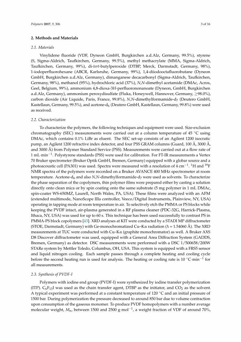
SEC elution chromatograms were analyzed to evaluate whether the entire PVDF-I macroinitiator was transformed. As an example, Figure 2 gives the SEC elution curves for PVDF-I with Mn = 2033 g·mol−1 and the block copolymer sample 1. The negative peak assigned to PVDF-I occurs at an elution time of 31 min, whereas the chromatogram of the block copolymer does not show any contributions from PVDF-I at 31 min. The elution curves of all other copolymers listed in Table 1 show no peak originating from PVDF-I. Contrary to reference [31] where a reaction time of 5 h and a temperature of 110 °C were selected, here 1 h and 90 °C were sufficient for complete conversion of the macroinitiator. The difference is suggested to be due to differences in UV irradiation and consequently differences in the generation of •Mn(CO)5 radicals.
Figure 1. Molecular weight distributions poly(vinylidene fluoride) with iodine end groups (PVDF-I).PVDF-I (dashed) and resulting block copolymer with methyl methacrylate (MMA) (full, sample 1).
SEC elution chromatograms were analyzed to evaluate whether the entire PVDF-I macroinitiatorwas transformed. As an example, Figure 2 gives the SEC elution curves for PVDF-I with Mn = 2033 g·mol−1
and the block copolymer sample 1. The negative peak assigned to PVDF-I occurs at an elution timeof 31 min, whereas the chromatogram of the block copolymer does not show any contributions fromPVDF-I at 31 min. The elution curves of all other copolymers listed in Table 1 show no peak originatingfrom PVDF-I. Contrary to reference [31] where a reaction time of 5 h and a temperature of 110 ◦C wereselected, here 1 h and 90 ◦C were sufficient for complete conversion of the macroinitiator. The differenceis suggested to be due to differences in UV irradiation and consequently differences in the generationof •Mn(CO)5 radicals.
Polymers 2017, 9, 306 6 of 16Polymers 2017, 9, 306 6 of 16
20 25 30 35 40
inte
nsity
PVDF-I PVDF-b-PMMA
elution time / min
Figure 2. Elution curve of PVDF-I with Mn = 2033 g·mol−1 and copolymer sample 1.
3.2. Block Copolymer Composition
Since the dispersities of PVDF-I and the block copolymer are rather close, it is anticipated that both chain ends, the CF2–I and the CH2–I end group, were transformed. To prove whether both end groups were activated and polymerized, end group analyses were carried out via 1H and 19F NMR spectroscopy. Firstly, a blank reaction of PVDF-I and Mn2(CO)10 in the absence of comonomer is considered. The reaction was performed with 100 mg PVDF-I dissolved in 3 mL DMAc containing 36 mg of Mn2(CO)10 (0.092 mmol) under UV irradiation at 40 °C for 3 h. The PVDF radical formed was expected to abstract an H atom either from the solvent or from the polymer. Figure 3 shows 1H NMR spectra of the original material (denoted PVDF-I) and PVDF obtained from the blank reaction (denoted PVDF-H). As expected PVDF-I shows both iodine end groups. According to reference [20] the peak at ~3.6 ppm is assigned to –CH2–CF2–I and the peak at around 3.8 ppm refers to –CF2–CH2–I. Both peaks are only very weak in the spectrum of PVDF–H. Instead, a peak at about 6.3 ppm is found, which refers to –CH2–CF2–H being due to transfer to solvent or polymer [46]. The red spectrum referring to PVDF–H also shows a peak at about 1.75 ppm, which represents –CF2–CH3 originating from –CF2–CH2–I after replacing I with H [46]. The single peak at δ ~ 4.55 ppm indicates the presence of –CH2–CF2–CH=CF2 [31], which originates from termination via disproportionation. Peaks at δ ~ 2.19 and 2.13 ppm represent the –CH2–CF2–CH=CF2 motif. The strong peak at δ ~ 2.8–3.0 ppm in both spectra refers to the –[CH2–CF2]n– head to tail PVDF sequence. The –CF2–CH2–CH2–CF2– head to head PVDF sequence is associated with a peak at δ ~ 2.4 which is however hardly seen in both spectra due to the very low Mn and consequently a small quantity of this sequence in the material. The acetone peak is seen around 2.05 ppm [46,47].
Figure 2. Elution curve of PVDF-I with Mn = 2033 g·mol−1 and copolymer sample 1.
3.2. Block Copolymer Composition
Since the dispersities of PVDF-I and the block copolymer are rather close, it is anticipated thatboth chain ends, the CF2–I and the CH2–I end group, were transformed. To prove whether both endgroups were activated and polymerized, end group analyses were carried out via 1H and 19F NMRspectroscopy. Firstly, a blank reaction of PVDF-I and Mn2(CO)10 in the absence of comonomer isconsidered. The reaction was performed with 100 mg PVDF-I dissolved in 3 mL DMAc containing36 mg of Mn2(CO)10 (0.092 mmol) under UV irradiation at 40 ◦C for 3 h. The PVDF radical formedwas expected to abstract an H atom either from the solvent or from the polymer. Figure 3 shows1H NMR spectra of the original material (denoted PVDF-I) and PVDF obtained from the blank reaction(denoted PVDF-H). As expected PVDF-I shows both iodine end groups. According to reference [20]the peak at ~3.6 ppm is assigned to –CH2–CF2–I and the peak at around 3.8 ppm refers to –CF2–CH2–I.Both peaks are only very weak in the spectrum of PVDF–H. Instead, a peak at about 6.3 ppm is found,which refers to –CH2–CF2–H being due to transfer to solvent or polymer [46]. The red spectrumreferring to PVDF–H also shows a peak at about 1.75 ppm, which represents –CF2–CH3 originatingfrom –CF2–CH2–I after replacing I with H [46]. The single peak at δ ~4.55 ppm indicates the presenceof –CH2–CF2–CH=CF2 [31], which originates from termination via disproportionation. Peaks at δ~2.19 and 2.13 ppm represent the –CH2–CF2–CH=CF2 motif. The strong peak at δ ~2.8–3.0 ppm in bothspectra refers to the –[CH2–CF2]n– head to tail PVDF sequence. The –CF2–CH2–CH2–CF2– head tohead PVDF sequence is associated with a peak at δ ~2.4 which is however hardly seen in both spectradue to the very low Mn and consequently a small quantity of this sequence in the material. The acetonepeak is seen around 2.05 ppm [46,47].

Polymers 2017, 9, 306 7 of 16Polymers 2017, 9, 306 7 of 16
6 5 4 3 2
δ / ppm
PVDF-I PVDF-H
D
AB
C
A: -CH2-CF2-IB: -CF2-CH2-IC: -CH2-CF2-HD: -CF2-CH2-H
Figure 3. 1H NMR spectra of PVDF-I (black) and PVDF-H (red).
The 1H NMR spectrum in Figure 4 recorded for a block copolymer of VDF and MMA shows the expected peaks. The very strong peak at about 3.6 ppm is assigned to the –OCH3 group of PMMA and two strong peaks between 0.8 and 1.2 ppm to the –CH3 group at the main chain of PMMA. In addition, the above-mentioned peaks assigned to the methylene group of PVDF at 2.4 and 3.0 ppm are seen. Integration of the peak at δ ~ 3.6 ppm for PMMA and at δ ~ 2.4 and 3.0 ppm for PVDF allows for the calculation of the ratio of block lengths according to Equation (1).
+
=ppm)(2.4CH
21)ppm(3.0CH
21
)ppm6.3(CH31
22
3
PVDF
PMMA
nn (1)
The example in Figure 4 represents a block copolymer with nPVDF to nPMMA of 1 to 0.67 (sample 5). The results for all block copolymers are given in Table 1.
4.0 3.5 3.0 2.5 2.0 1.5 1.0
-CF2-CH2-CH2-CF2-
δ / ppm
PVDF-b-PMMA
-CH3
-(CH2-CF2)n
-OCH3 acetone
Figure 4. 1H NMR spectrum of block copolymer sample 5.
The 1H–NMR spectrum in Figure 5 recorded for a block copolymer consisting of VDF and styrene shows also the expected peaks. The strong peaks at around 6.6 to 7.2 ppm are assigned to the –C6H5 group of PS. Two other peaks at 1.94 ppm (–CH2–CH–(C6H5)–) and 1.63 ppm (–CH2–CH–(C6H5)–) also belong to PS. In addition, the peaks at 3.0 and 2.4 ppm assigned to the methylene groups
Figure 3. 1H NMR spectra of PVDF-I (black) and PVDF-H (red).
The 1H NMR spectrum in Figure 4 recorded for a block copolymer of VDF and MMA shows theexpected peaks. The very strong peak at about 3.6 ppm is assigned to the –OCH3 group of PMMA andtwo strong peaks between 0.8 and 1.2 ppm to the –CH3 group at the main chain of PMMA. In addition,the above-mentioned peaks assigned to the methylene group of PVDF at 2.4 and 3.0 ppm are seen.Integration of the peak at δ ~3.6 ppm for PMMA and at δ ~2.4 and 3.0 ppm for PVDF allows for thecalculation of the ratio of block lengths according to Equation (1).
nPMMA
nPVDF=
13∫
CH3(3.6 ppm)
12∫
CH2(3.0 ppm) +12∫
CH2(2.4 ppm)(1)
The example in Figure 4 represents a block copolymer with nPVDF to nPMMA of 1 to 0.67 (sample 5).The results for all block copolymers are given in Table 1.
Polymers 2017, 9, 306 7 of 16
6 5 4 3 2
δ / ppm
PVDF-I PVDF-H
D
AB
C
A: -CH2-CF2-IB: -CF2-CH2-IC: -CH2-CF2-HD: -CF2-CH2-H
Figure 3. 1H NMR spectra of PVDF-I (black) and PVDF-H (red).
The 1H NMR spectrum in Figure 4 recorded for a block copolymer of VDF and MMA shows the expected peaks. The very strong peak at about 3.6 ppm is assigned to the –OCH3 group of PMMA and two strong peaks between 0.8 and 1.2 ppm to the –CH3 group at the main chain of PMMA. In addition, the above-mentioned peaks assigned to the methylene group of PVDF at 2.4 and 3.0 ppm are seen. Integration of the peak at δ ~ 3.6 ppm for PMMA and at δ ~ 2.4 and 3.0 ppm for PVDF allows for the calculation of the ratio of block lengths according to Equation (1).
+
=ppm)(2.4CH
21)ppm(3.0CH
21
)ppm6.3(CH31
22
3
PVDF
PMMA
nn (1)
The example in Figure 4 represents a block copolymer with nPVDF to nPMMA of 1 to 0.67 (sample 5). The results for all block copolymers are given in Table 1.
4.0 3.5 3.0 2.5 2.0 1.5 1.0
-CF2-CH2-CH2-CF2-
δ / ppm
PVDF-b-PMMA
-CH3
-(CH2-CF2)n
-OCH3 acetone
Figure 4. 1H NMR spectrum of block copolymer sample 5.
The 1H–NMR spectrum in Figure 5 recorded for a block copolymer consisting of VDF and styrene shows also the expected peaks. The strong peaks at around 6.6 to 7.2 ppm are assigned to the –C6H5 group of PS. Two other peaks at 1.94 ppm (–CH2–CH–(C6H5)–) and 1.63 ppm (–CH2–CH–(C6H5)–) also belong to PS. In addition, the peaks at 3.0 and 2.4 ppm assigned to the methylene groups
Figure 4. 1H NMR spectrum of block copolymer sample 5.
The 1H–NMR spectrum in Figure 5 recorded for a block copolymer consisting of VDF and styreneshows also the expected peaks. The strong peaks at around 6.6 to 7.2 ppm are assigned to the –C6H5
Polymers 2017, 9, 306 8 of 16
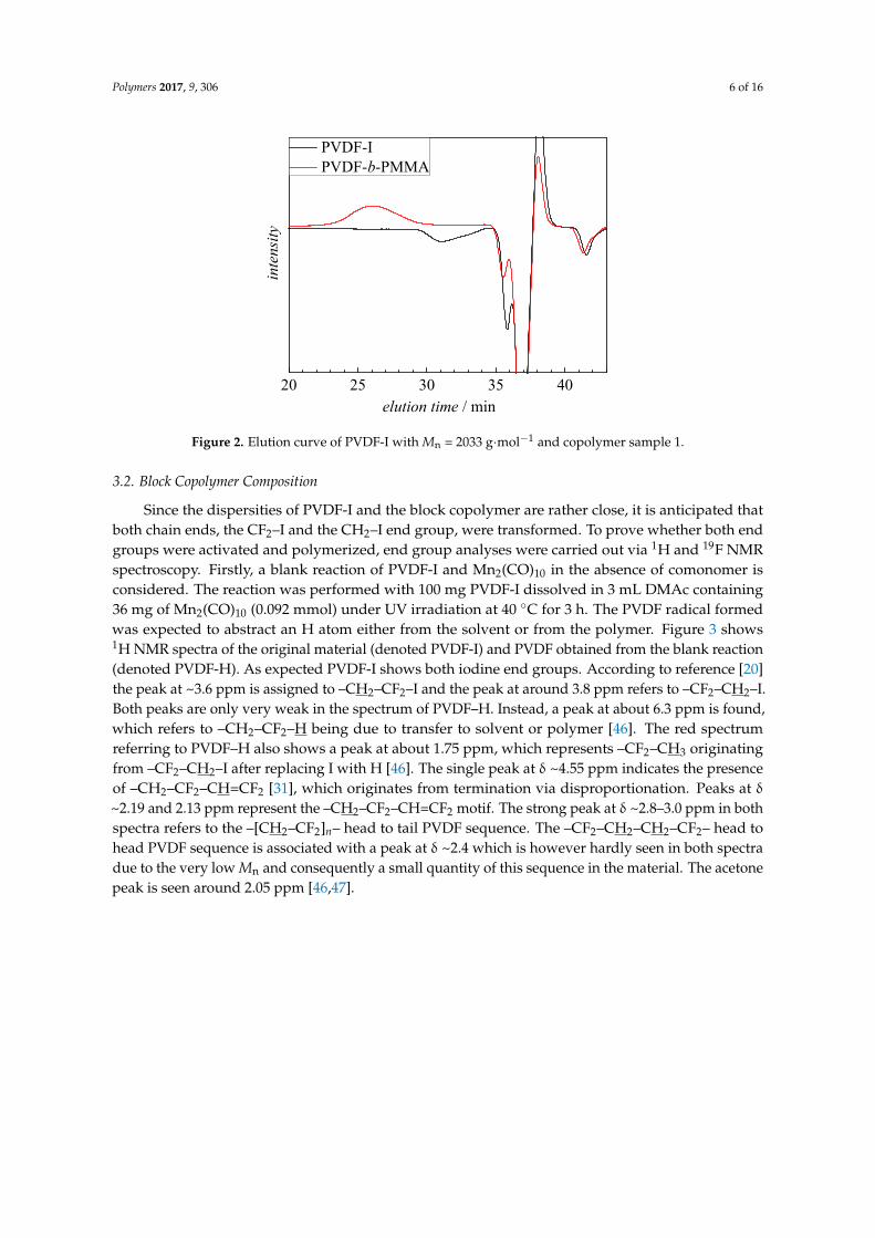
group of PS. Two other peaks at 1.94 ppm (–CH2–CH–(C6H5)–) and 1.63 ppm (–CH2–CH–(C6H5)–)also belong to PS. In addition, the peaks at 3.0 and 2.4 ppm assigned to the methylene groups in PVDFare seen. Integration of the peaks at 6.6 to 7.2 ppm for PS and at 2.4 and 3.0 ppm for PVDF allows forthe calculation of the ratio of block lengths according to Equation (2).
nPS
nPVDF=
15∫
C6H5(6.6 to 7.2 ppm)
12∫
CH2(3.0 ppm) +12∫
CH2(2.4 ppm)(2)
The example in Figure 5 represents a block copolymer with nPVDF to nPS of 1 to 0.56. The resultsfor all block copolymers containing styrene are listed in Table 1.
Polymers 2017, 9, 306 8 of 16
in PVDF are seen. Integration of the peaks at 6.6 to 7.2 ppm for PS and at 2.4 and 3.0 ppm for PVDF allows for the calculation of the ratio of block lengths according to Equation (2).
)ppm4.2(CH21)ppm0.3(CH
21
ppm)7.2to6.6(HC51
22
56
PVDF
PS
+
=nn (2)
The example in Figure 5 represents a block copolymer with nPVDF to nPS of 1 to 0.56. The results for all block copolymers containing styrene are listed in Table 1.
8 7 6 5 4 3 2 1
a*
-CH2-CH(C6H5)-
δ / ppm
PVDF-b-PS
C6H5
-(CH2-CF2)
-CF2-CH2-CH2-CF2-
acetonea
b
c d
e
e
b
a,a*d c
Figure 5. 1H NMR spectrum of block copolymer sample 9.
The 19F–NMR results also show that –CH2–CF2–I and –CF2–CH2–I chain ends of the PVDF macroinitiator were activated and polymerized. Peaks at δ ~ −38.4 ppm and δ ~ –108 ppm referring to –CH2–CF2–I and –CF2–CH2–I [31,47] respectively, of the macroinitiator clearly disappeared after copolymerization (see Figure S1 in Supporting Information).
3.3. Crystallinity of the Block Copolymers
To obtain additional information on the crystallinity of the products, FT-IR spectra were recorded. The FT-IR spectra of PVDF homopolymer and the block copolymers are given in Figure 6. One of the most prominent difference is the strong band at 1730 cm−1, which is assigned to the carbonyl group in PMMA (blue spectrum) which is absent in the PVDF spectrum. In addition, the IR spectrum of the PMMA block copolymer shows a broad peak at 2951 cm−1 assigned to –OCH3 of PMMA. The spectrum of the block copolymer with PS (red spectrum) shows the aromatic C–H stretching vibrations at 2850, 2923, 3025, and 3060 cm−1. The peaks at 1493 and 1062 cm−1 are assigned to the aromatic C–C bond stretching vibration. The absorbances at 3000 and 3100 cm−1 represent the C–C vibrations and peaks at 1151 cm−1, as well as at 1193 cm−1 for C–F vibrations of the PVDF block [30,48]. The spectra clearly indicate the presence of both monomer units in the products.
Figure 5. 1H NMR spectrum of block copolymer sample 9.
The 19F–NMR results also show that –CH2–CF2–I and –CF2–CH2–I chain ends of the PVDFmacroinitiator were activated and polymerized. Peaks at δ ~ −38.4 ppm and δ ~ –108 ppm referringto –CH2–CF2–I and –CF2–CH2–I [31,47] respectively, of the macroinitiator clearly disappeared aftercopolymerization (see Figure S1 in Supporting Information).
3.3. Crystallinity of the Block Copolymers
To obtain additional information on the crystallinity of the products, FT-IR spectra were recorded.The FT-IR spectra of PVDF homopolymer and the block copolymers are given in Figure 6. One of themost prominent difference is the strong band at 1730 cm−1, which is assigned to the carbonyl group inPMMA (blue spectrum) which is absent in the PVDF spectrum. In addition, the IR spectrum of thePMMA block copolymer shows a broad peak at 2951 cm−1 assigned to –OCH3 of PMMA. The spectrumof the block copolymer with PS (red spectrum) shows the aromatic C–H stretching vibrations at 2850,2923, 3025, and 3060 cm−1. The peaks at 1493 and 1062 cm−1 are assigned to the aromatic C–C bondstretching vibration. The absorbances at 3000 and 3100 cm−1 represent the C–C vibrations and peaksat 1151 cm−1, as well as at 1193 cm−1 for C–F vibrations of the PVDF block [30,48]. The spectra clearlyindicate the presence of both monomer units in the products.

Polymers 2017, 9, 306 9 of 16Polymers 2017, 9, 306 9 of 16
1000 2000 3000 4000
abso
rban
ce /
a.u.
wavenumber (cm-1)
PVDF-I PVDF-b-PS PVDF-b-PMMA
-C=O
-C6H5
400 600 800 1000 1200
β
β
αα
β
β
α α
β
β
abso
rban
ce /
a.u.
wavenumber (cm-1)
Figure 6. FT-IR results of PVDF-I (black), PVDF-b-PMMA (blue, sample 1), and PVDF-b-PS (red, sample 9). The vertical lines indicate peaks that are representative of either the α or β crystalline phase of PVDF.
To obtain information on the crystallinity of the PVDF block, the enlarged spectra in the wavenumber range from 500 to 1300 cm−1 depicted in the lower part of Figure 6 are considered. The spectrum of the PVDF-I macroinitiator shows distinct peaks at 532, 614, 795, and 976 cm−1 indicating the presence of α phase PVDF. On the contrary, the spectra of the block copolymers show none of the above mentioned peaks. New peaks at 510, 841, and 1276 cm−1 occur, which suggest the presence of β crystalline PVDF domains in the copolymer. Thus, the formation of PVDF-b-PMMA or PVDF-b-PS is suggested to be associated with a change in crystallinity of the PVDF segments.
The peak at 841 cm−1 in the IR spectrum may also be indicative of γ phase material, however, peaks at 776, 812, 833, and 1234 cm−1 also typical for the γ phase are not seen. As pointed out in literature, the flawless identification of β phase PVDF requires additional analyses such as XRD [13]. The results from XRD of PVDF-I and two block copolymers (sample 1 and 9 in Table 1) are depicted in Figure 7. The spectra are clearly different. The PVDF-I curve shows peaks at 2θ values of 17.66°, 18.30°, 19.90°, and 26.56°, which are related to the α phase [13]. On the other hand for the block copolymers only one peak with a maximum at around 20.26° is observed, which indicates the presence of β phase material. Peaks typical for the γ phase at 2θ values of 18.50°, 19.20° or 20.04° are not found [13]. Thus, the results from FT-IR and XRD strongly suggest the transformation of α to β phase PVDF domains in the copolymer. In addition, DSC analyses yield melting temperatures of 165
Figure 6. FT-IR results of PVDF-I (black), PVDF-b-PMMA (blue, sample 1), and PVDF-b-PS (red, sample9). The vertical lines indicate peaks that are representative of either the α or β crystalline phase of PVDF.
To obtain information on the crystallinity of the PVDF block, the enlarged spectra in thewavenumber range from 500 to 1300 cm−1 depicted in the lower part of Figure 6 are considered.The spectrum of the PVDF-I macroinitiator shows distinct peaks at 532, 614, 795, and 976 cm−1
indicating the presence of α phase PVDF. On the contrary, the spectra of the block copolymers shownone of the above mentioned peaks. New peaks at 510, 841, and 1276 cm−1 occur, which suggest thepresence of β crystalline PVDF domains in the copolymer. Thus, the formation of PVDF-b-PMMA orPVDF-b-PS is suggested to be associated with a change in crystallinity of the PVDF segments.
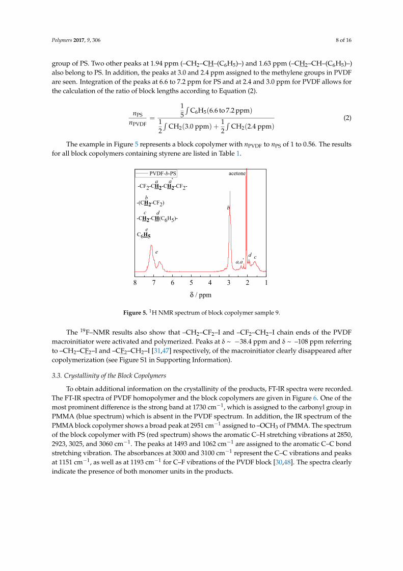
The peak at 841 cm−1 in the IR spectrum may also be indicative of γ phase material, however,peaks at 776, 812, 833, and 1234 cm−1 also typical for the γ phase are not seen. As pointed out inliterature, the flawless identification of β phase PVDF requires additional analyses such as XRD [13].The results from XRD of PVDF-I and two block copolymers (sample 1 and 9 in Table 1) are depicted inFigure 7. The spectra are clearly different. The PVDF-I curve shows peaks at 2θ values of 17.66◦, 18.30◦,19.90◦, and 26.56◦, which are related to the α phase [13]. On the other hand for the block copolymersonly one peak with a maximum at around 20.26◦ is observed, which indicates the presence of β phasematerial. Peaks typical for the γ phase at 2θ values of 18.50◦, 19.20◦ or 20.04◦ are not found [13].Thus, the results from FT-IR and XRD strongly suggest the transformation of α to β phase PVDFdomains in the copolymer. In addition, DSC analyses yield melting temperatures of 165 ◦C for the
Polymers 2017, 9, 306 10 of 16
block copolymers and 172 ◦C for the PVDF macroinitiator. These temperatures are characteristic for αand β phase material. Since γ phase PVDF is associated with melting temperatures between 180 and190 ◦C [13] the presence of γ phase PVDF can be excluded.
Polymers 2017, 9, 306 10 of 16
°C for the block copolymers and 172 °C for the PVDF macroinitiator. These temperatures are characteristic for α and β phase material. Since γ phase PVDF is associated with melting temperatures between 180 and 190 °C [13] the presence of γ phase PVDF can be excluded.
10 15 20 25 30
inte
nsity
/ a.
u.
2θ / °
PVDF-I PVDF-b-PS PVDF-b-PMMA
α (100)
α (020) α (110)
α (021)
β
β (110)/(200)
Figure 7. XRD results of PVDF-I (black), block copolymer with MMA (sample 4, blue) and block copolymer with styrene (sample 11, red).
The results demonstrate that the crystal structure of PVDF moieties is transformed from α to β after block copolymer synthesis. To identify which ratio of PVDF block length, nPVDF, to comonomer block length, nco, is required for this transformation a number of block copolymers was synthesized. For nVDF/nco ranging from 0.25 to 100 the characteristic IR peaks assigned to β phase material were found. In addition, contributions from α phase were observed. In cases where this ratio was between 1.4 and 5 exclusively the IR peaks indicative of β phase material were detected. With decreasing block length ratio nPVDF/nco the fraction of crystalline material is reduced. In addition to the block length ratio, the absolute lengths of both blocks is important to be considered. The data presented here refer to PVDF segments with lengths between 27 and 153 monomer units. In future, longer PVDF segments need to be used as well.
According to references [16,48–50] the miscibility of PVDF and PMMA does not depend on temperature, which is attributed to interactions between the carbonyl group of PMMA and the dipole moment of PVDF as well as hydrogen bonding. Because of steric reasons, the above-mentioned interactions lead to an all trans conformation in both polymers. Further, the presence of MMA units may alter the glass transition temperature of PVDF, which affects the relative growth rates of α and β polymorphs [16].
According to dynamic mechanical measurements, pure PVDF may undergo four relaxations when frequency and temperature are changed [51,52]. One of these relaxations, which is associated with the glass transition may be shifted to higher frequencies and pressures after addition of PMMA. Essentially, PMMA facilitates relaxation from a lower energy level, which may be explained by breaking the interactions and correlations between the PVDF permanent moments in the amorphous-crystalline-interphase and improving the dielectric relaxation possibilities [16].
The piezoelectricity and pyroelectricity of PVDF are associated with the existence of a remnant polarization that is proportional to the degree of crystallinity [16]. PMMA, as the amorphous phase, surrounds individual crystallites, and therefore, affects the degree of crystallinity.
Figure 8 compares the XRD results of samples 6, 7, and 8 with PMMA volume fractions of 33%, 46%, and 66%, respectively, in the block copolymer. While it is clearly seen that no significant contributions from α phase are contained, a quantitative comparison of the XRD results of different samples is not feasible. However, the DSC results show that the integration of the melting peak and the degree of crystallinity are proportional to block lengths ratio and volume fraction of PMMA in
Figure 7. XRD results of PVDF-I (black), block copolymer with MMA (sample 4, blue) and blockcopolymer with styrene (sample 11, red).
The results demonstrate that the crystal structure of PVDF moieties is transformed from α to βafter block copolymer synthesis. To identify which ratio of PVDF block length, nPVDF, to comonomerblock length, nco, is required for this transformation a number of block copolymers was synthesized.For nVDF/nco ranging from 0.25 to 100 the characteristic IR peaks assigned to β phase material werefound. In addition, contributions from α phase were observed. In cases where this ratio was between1.4 and 5 exclusively the IR peaks indicative of β phase material were detected. With decreasing blocklength ratio nPVDF/nco the fraction of crystalline material is reduced. In addition to the block lengthratio, the absolute lengths of both blocks is important to be considered. The data presented here referto PVDF segments with lengths between 27 and 153 monomer units. In future, longer PVDF segmentsneed to be used as well.
According to references [16,48–50] the miscibility of PVDF and PMMA does not depend ontemperature, which is attributed to interactions between the carbonyl group of PMMA and the dipolemoment of PVDF as well as hydrogen bonding. Because of steric reasons, the above-mentionedinteractions lead to an all trans conformation in both polymers. Further, the presence of MMA unitsmay alter the glass transition temperature of PVDF, which affects the relative growth rates of α and βpolymorphs [16].
According to dynamic mechanical measurements, pure PVDF may undergo four relaxationswhen frequency and temperature are changed [51,52]. One of these relaxations, which is associatedwith the glass transition may be shifted to higher frequencies and pressures after addition ofPMMA. Essentially, PMMA facilitates relaxation from a lower energy level, which may be explainedby breaking the interactions and correlations between the PVDF permanent moments in theamorphous-crystalline-interphase and improving the dielectric relaxation possibilities [16].
The piezoelectricity and pyroelectricity of PVDF are associated with the existence of a remnantpolarization that is proportional to the degree of crystallinity [16]. PMMA, as the amorphous phase,surrounds individual crystallites, and therefore, affects the degree of crystallinity.
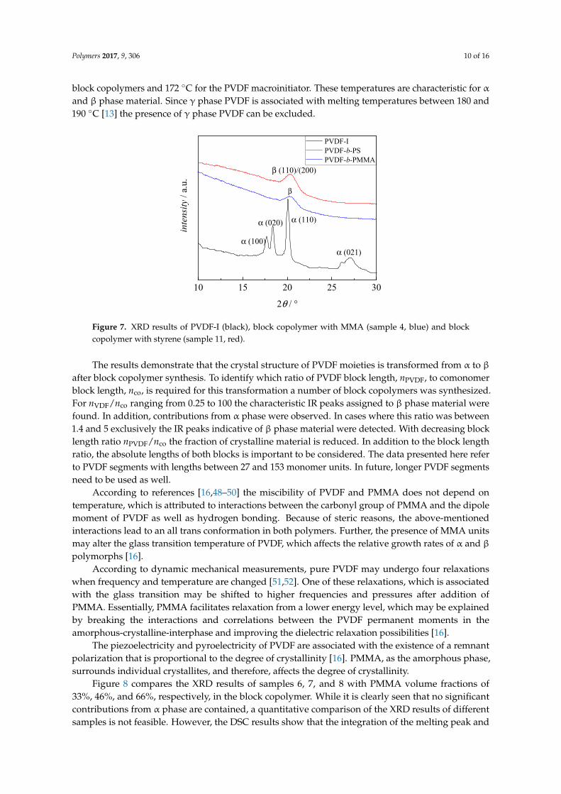
Figure 8 compares the XRD results of samples 6, 7, and 8 with PMMA volume fractions of33%, 46%, and 66%, respectively, in the block copolymer. While it is clearly seen that no significantcontributions from α phase are contained, a quantitative comparison of the XRD results of differentsamples is not feasible. However, the DSC results show that the integration of the melting peak and

Polymers 2017, 9, 306 11 of 16
the degree of crystallinity are proportional to block lengths ratio and volume fraction of PMMA in theblock copolymer. In all cases, the integrals of the melting peak and the degree of crystallinity decrease,if the volume fraction of PMMA in the block copolymer increases.
Polymers 2017, 9, 306 11 of 16
the block copolymer. In all cases, the integrals of the melting peak and the degree of crystallinity decrease, if the volume fraction of PMMA in the block copolymer increases.
14 16 18 20 22 24 26
inte
nsity
/ a.
u.
2θ / °
nVDF/nCO 1:0.21 nVDF/nCO 1:0.37 nVDF/nCO 1:0.84
β (110) (200)
Figure 8. XRD curves for sample 6 (blue), 7 (red), and 8 (green) with the block length ratios as indicated.
Interestingly the block copolymers with PS as second block also show β phase crystallinity. The reason for this behavior is not yet clear. It may be suspected that the aromatic groups are directing the conformation to an all trans structure of PVDF. For low molecular weight species interactions between F atoms and for example aromatic rings were reported [53–56].
3.4. Phase Separation
To test for microphase separation of the two polymer blocks, AFM analyses of thin films of samples 4, 6, 10, and 11 obtained by spin coating on mica were carried out. Without selective etching of the PMMA or PS block by air-plasma, flat films were obtained that did not show any phase separation as indicated by the phase-image of the AFM (not shown). The phase-image contrasts in a semi-quantitative way differences in the material properties, e.g., hardness and viscoelasticity. After 10 s of air plasma treatment for every sample, a height variation in the topography image on the left hand side of Figures 9–12 is visible and the phase image on the right hand side of these figures shows small domains in a continuous matrix. These domains may be associated with a PVDF-rich microphase and the size of these domains scales with the volume fraction of PVDF in the copolymer. In Figures 9 and 10, it is notable that the continuous matrix in which the PVDF-domains are embedded covers a much smaller surface fraction in sample 6 compared to sample 4. This observation corresponds with the lower PMMA volume fraction of ϕco = 0.33 in sample 6 compared to ϕco = 0.85 in sample 4. Control experiments with blends of PMMA and PVDF homopolymers showed no phase separation.
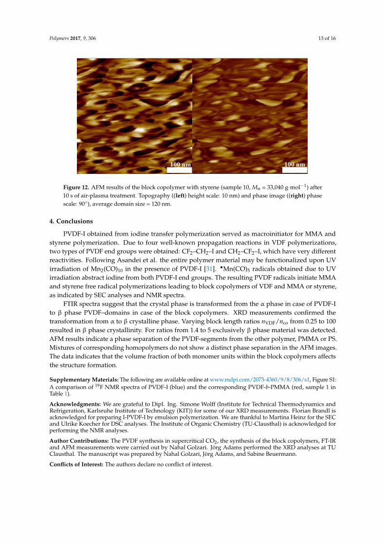
AFM measurements at identical conditions were carried out for two copolymers with styrene blocks of different length (Figures 11 and 12). As expected, the size of the domains are proportional to the PVDF volume fraction in the copolymer. In Figure 12, it is notable that the continuous matrix containing the PVDF–domains covers a smaller surface fraction in sample 10 compared to sample 11 (Figure 11) because of the lower value of ϕco = 0.50 compared to ϕco = 0.58, respectively.
Figure 8. XRD curves for sample 6 (blue), 7 (red), and 8 (green) with the block length ratios as indicated.
Interestingly the block copolymers with PS as second block also show β phase crystallinity.The reason for this behavior is not yet clear. It may be suspected that the aromatic groups are directingthe conformation to an all trans structure of PVDF. For low molecular weight species interactionsbetween F atoms and for example aromatic rings were reported [53–56].
3.4. Phase Separation
To test for microphase separation of the two polymer blocks, AFM analyses of thin films ofsamples 4, 6, 10, and 11 obtained by spin coating on mica were carried out. Without selective etchingof the PMMA or PS block by air-plasma, flat films were obtained that did not show any phaseseparation as indicated by the phase-image of the AFM (not shown). The phase-image contrasts in asemi-quantitative way differences in the material properties, e.g., hardness and viscoelasticity. After 10s of air plasma treatment for every sample, a height variation in the topography image on the left handside of Figures 9–12 is visible and the phase image on the right hand side of these figures shows smalldomains in a continuous matrix. These domains may be associated with a PVDF-rich microphaseand the size of these domains scales with the volume fraction of PVDF in the copolymer. In Figures 9and 10, it is notable that the continuous matrix in which the PVDF-domains are embedded coversa much smaller surface fraction in sample 6 compared to sample 4. This observation correspondswith the lower PMMA volume fraction of ϕco = 0.33 in sample 6 compared to ϕco = 0.85 in sample 4.Control experiments with blends of PMMA and PVDF homopolymers showed no phase separation.
AFM measurements at identical conditions were carried out for two copolymers with styreneblocks of different length (Figures 11 and 12). As expected, the size of the domains are proportionalto the PVDF volume fraction in the copolymer. In Figure 12, it is notable that the continuous matrixcontaining the PVDF–domains covers a smaller surface fraction in sample 10 compared to sample 11(Figure 11) because of the lower value of ϕco = 0.50 compared to ϕco = 0.58, respectively.

Polymers 2017, 9, 306 12 of 16
Polymers 2017, 9, 306 12 of 16
Figure 9. Atomic Force Microscopy (AFM) results of the block copolymer with MMA (sample 6) with Mn = 12,080 g·mol−1 after 10 s of air-plasma treatment. Topography ((left) height scale: 5 nm) and phase image ((right) phase scale: 90°), Average domain size = 50 nm.
Figure 10. AFM results of the block copolymer with MMA (sample 4, Mn = 39,450 g·mol−1) after 10 s of air plasma treatment. Topography ((left) height scale: 10 nm) and phase image ((right) phase scale: 50°), average domain size = 75 nm.
Figure 11. AFM results of the block copolymer with styrene (sample 11, Mn = 19,856 g·mol−1) after 10 s of air-plasma treatment. Topography ((left) height scale: 10 nm) and phase image ((right) phase scale: 30°), average domain size = 80 nm.
Figure 9. Atomic Force Microscopy (AFM) results of the block copolymer with MMA (sample 6) withMn = 12,080 g·mol−1 after 10 s of air-plasma treatment. Topography ((left) height scale: 5 nm) andphase image ((right) phase scale: 90◦), Average domain size = 50 nm.
Polymers 2017, 9, 306 12 of 16
Figure 9. Atomic Force Microscopy (AFM) results of the block copolymer with MMA (sample 6) with Mn = 12,080 g·mol−1 after 10 s of air-plasma treatment. Topography ((left) height scale: 5 nm) and phase image ((right) phase scale: 90°), Average domain size = 50 nm.
Figure 10. AFM results of the block copolymer with MMA (sample 4, Mn = 39,450 g·mol−1) after 10 s of air plasma treatment. Topography ((left) height scale: 10 nm) and phase image ((right) phase scale: 50°), average domain size = 75 nm.
Figure 11. AFM results of the block copolymer with styrene (sample 11, Mn = 19,856 g·mol−1) after 10 s of air-plasma treatment. Topography ((left) height scale: 10 nm) and phase image ((right) phase scale: 30°), average domain size = 80 nm.
Figure 10. AFM results of the block copolymer with MMA (sample 4, Mn = 39,450 g·mol−1) after 10 sof air plasma treatment. Topography ((left) height scale: 10 nm) and phase image ((right) phase scale:50◦), average domain size = 75 nm.
Polymers 2017, 9, 306 12 of 16
Figure 9. Atomic Force Microscopy (AFM) results of the block copolymer with MMA (sample 6) with Mn = 12,080 g·mol−1 after 10 s of air-plasma treatment. Topography ((left) height scale: 5 nm) and phase image ((right) phase scale: 90°), Average domain size = 50 nm.
Figure 10. AFM results of the block copolymer with MMA (sample 4, Mn = 39,450 g·mol−1) after 10 s of air plasma treatment. Topography ((left) height scale: 10 nm) and phase image ((right) phase scale: 50°), average domain size = 75 nm.
Figure 11. AFM results of the block copolymer with styrene (sample 11, Mn = 19,856 g·mol−1) after 10 s of air-plasma treatment. Topography ((left) height scale: 10 nm) and phase image ((right) phase scale: 30°), average domain size = 80 nm.
Figure 11. AFM results of the block copolymer with styrene (sample 11, Mn = 19,856 g·mol−1) after10 s of air-plasma treatment. Topography ((left) height scale: 10 nm) and phase image ((right) phasescale: 30◦), average domain size = 80 nm.
Polymers 2017, 9, 306 13 of 16
Polymers 2017, 9, 306 13 of 16
Figure 12. AFM results of the block copolymer with styrene (sample 10, Mn = 33,040 g·mol−1) after 10 s of air-plasma treatment. Topography ((left) height scale: 10 nm) and phase image ((right) phase scale: 90°), average domain size = 120 nm.
4. Conclusions
PVDF-I obtained from iodine transfer polymerization served as macroinitiator for MMA and styrene polymerization. Due to four well-known propagation reactions in VDF polymerizations, two types of PVDF end groups were obtained: CF2–CH2–I and CH2–CF2–I, which have very different reactivities. Following Asandei et al. the entire polymer material may be functionalized upon UV irradiation of Mn2(CO)10 in the presence of PVDF-I [31]. •Mn(CO)5 radicals obtained due to UV irradiation abstract iodine from both PVDF-I end groups. The resulting PVDF radicals initiate MMA and styrene free radical polymerizations leading to block copolymers of VDF and MMA or styrene, as indicated by SEC analyses and NMR spectra.
FTIR spectra suggest that the crystal phase is transformed from the α phase in case of PVDF-I to β phase PVDF–domains in case of the block copolymers. XRD measurements confirmed the transformation from α to β crystalline phase. Varying block length ratios nVDF/nco from 0.25 to 100 resulted in β phase crystallinity. For ratios from 1.4 to 5 exclusively β phase material was detected. AFM results indicate a phase separation of the PVDF-segments from the other polymer, PMMA or PS. Mixtures of corresponding homopolymers do not show a distinct phase separation in the AFM images. The data indicates that the volume fraction of both monomer units within the block copolymers affects the structure formation.
Supplementary Materials: The following are available online at www.mdpi.com/2073-4360/9/8/306/s1, Figure S1: A comparison of 19F NMR spectra of PVDF-I (blue) and the corresponding PVDF-b-PMMA (red, sample 1 in Table 1).
Acknowledgments: We are grateful to Dipl. Ing. Simone Wolff (Institute for Technical Thermodynamics and Refrigeration, Karlsruhe Institute of Technology (KIT)) for some of our XRD measurements. Florian Brandl is acknowledged for preparing I-PVDF-I by emulsion polymerization. We are thankful to Martina Heinz for the SEC and Ulrike Koecher for DSC analyses. The Institute of Organic Chemistry (TU-Clausthal) is acknowledged for performing the NMR analyses.
Author Contributions: The PVDF synthesis in supercritical CO2, the synthesis of the block copolymers, FT-IR and AFM measurements were carried out by Nahal Golzari. Jörg Adams performed the XRD analyses at TU Clausthal. The manuscript was prepared by Nahal Golzari, Jörg Adams, and Sabine Beuermann.
Conflicts of Interest: The authors declare no conflict of interest.
Figure 12. AFM results of the block copolymer with styrene (sample 10, Mn = 33,040 g·mol−1) after10 s of air-plasma treatment. Topography ((left) height scale: 10 nm) and phase image ((right) phasescale: 90◦), average domain size = 120 nm.
4. Conclusions
PVDF-I obtained from iodine transfer polymerization served as macroinitiator for MMA andstyrene polymerization. Due to four well-known propagation reactions in VDF polymerizations,two types of PVDF end groups were obtained: CF2–CH2–I and CH2–CF2–I, which have very differentreactivities. Following Asandei et al. the entire polymer material may be functionalized upon UVirradiation of Mn2(CO)10 in the presence of PVDF-I [31]. •Mn(CO)5 radicals obtained due to UVirradiation abstract iodine from both PVDF-I end groups. The resulting PVDF radicals initiate MMAand styrene free radical polymerizations leading to block copolymers of VDF and MMA or styrene,as indicated by SEC analyses and NMR spectra.
FTIR spectra suggest that the crystal phase is transformed from the α phase in case of PVDF-Ito β phase PVDF–domains in case of the block copolymers. XRD measurements confirmed thetransformation from α to β crystalline phase. Varying block length ratios nVDF/nco from 0.25 to 100resulted in β phase crystallinity. For ratios from 1.4 to 5 exclusively β phase material was detected.AFM results indicate a phase separation of the PVDF-segments from the other polymer, PMMA or PS.Mixtures of corresponding homopolymers do not show a distinct phase separation in the AFM images.The data indicates that the volume fraction of both monomer units within the block copolymers affectsthe structure formation.
Supplementary Materials: The following are available online at www.mdpi.com/2073-4360/9/8/306/s1, Figure S1:A comparison of 19F NMR spectra of PVDF-I (blue) and the corresponding PVDF-b-PMMA (red, sample 1 inTable 1).
Acknowledgments: We are grateful to Dipl. Ing. Simone Wolff (Institute for Technical Thermodynamics andRefrigeration, Karlsruhe Institute of Technology (KIT)) for some of our XRD measurements. Florian Brandl isacknowledged for preparing I-PVDF-I by emulsion polymerization. We are thankful to Martina Heinz for the SECand Ulrike Koecher for DSC analyses. The Institute of Organic Chemistry (TU-Clausthal) is acknowledged forperforming the NMR analyses.
Author Contributions: The PVDF synthesis in supercritical CO2, the synthesis of the block copolymers, FT-IRand AFM measurements were carried out by Nahal Golzari. Jörg Adams performed the XRD analyses at TUClausthal. The manuscript was prepared by Nahal Golzari, Jörg Adams, and Sabine Beuermann.
Conflicts of Interest: The authors declare no conflict of interest.
Polymers 2017, 9, 306 14 of 16
References
1. Humphrey, J.S.; Amin-Sanayei, R. Vinylidene Fluoride Polymers. In Encyclopedia of Polymer Science andTechnology, 3rd ed.; Wiley: New York, NY, USA, 2002; pp. 510–533.
2. Scheirs, J. Modern Fluoropolymers: High Performance Polymers for Diverse Applications; Wiley: Chichester, UK;New York, NY, USA, 1997; ISBN 978-0-471-97055-2.
3. Ameduri, B. From Vinylidene Fluoride (VDF) to the Applications of VDF-Containing Polymers andCopolymers: Recent Developments and Future Trends. Chem. Rev. 2009, 109, 6632–6686. [CrossRef][PubMed]
4. Beuermann, S.; Imran-ul-haq, M. Homogeneous phase polymerization of vinylidene fluoride in supercriticalCO2: Surfactant free synthesis and kinetics. Macromol. Symp. 2007, 259, 210–217. [CrossRef]
5. Lu, F.J.; Hsu, S.L. Study of the crystallization behavior of poly(vinylidene fluoride) from melt under theeffect of an electric field. Macromolecules 1986, 19, 326–329. [CrossRef]
6. Kawai, H. The Piezoelectricity of Poly(vinylidene fluoride). Jpn. J. Appl. Phys. 1969, 8, 975–976. [CrossRef]7. Bergman, J.G., Jr.; Mcfee, J.H.; Crane, G.R. Pyroelectricity and optical second harmonic generation in
poly(vinylidene fluoride) films. Appl. Phys. Lett. 1971, 18, 203. [CrossRef]8. Nakamura, K.; Wada, Y. Piezoelectricity, pyroelectricity, and the electrostriction constant of poly(vinylidene
fluoride). J. Polym. Sci. Part B Polym. Phys. 1971, 9, 161–173. [CrossRef]9. Lovinger, A.J. Molecular Mechanism for α (δ Transformation in Electrically Poled Poly(vinylidene fluoride)).
Macromolecules 1981, 14, 225–227. [CrossRef]10. Kepler, R.G. Ferroelectric, Pyroelectric, and Piezoelectric Properties of Poly(vinylidene fluoride) in Ferroelectric
Polymers Chemistry, in Physics and Applications; Nalwa, H.S., Ed.; CRC Press: New York, NY, USA, 1995; p. 183,ISBN 0-8247-9468-0.
11. Hasegawa, R.; Kobayashi, M.; Tadokoro, H. Molecular conformation and packing of poly(vinylidenefluoride). Stability of three crystalline forms and the effect of high pressure. Polym. J. 1972, 3, 591–599.[CrossRef]
12. Lovinger, A.; Reed, D. Inhomogeneous Thermal Degradation of Poly(vinylidene fluoride) Crystallized fromthe Melt. Macromolecules 1980, 13, 989–994. [CrossRef]
13. Martins, P.; Lopes, A.C.; Lanceros-Mendez, S. Electroactive phases of poly(vinylidene fluoride):Determination, processing and applications. Prog. Polym. Sci. 2014, 39, 683–706. [CrossRef]
14. Fukada, E. History and recent progress in piezoelectric polymers. IEEE Trans. Ultrason. Ferroelectr.Freq. Control 2000, 47, 1277–1290. [CrossRef] [PubMed]
15. Bauer, F. Relaxor fluorinated polymers: Novel applications and recent developments. IEEE Trans. Dielectr.Electr. Insul. 2010, 17, 1106–1112. [CrossRef]
16. Jungnickel, B.J. PVDF and Its Blends. In Ferroelectric Polymers Chemistry, in Physics and Applications;Nalwa, H.S., Ed.; CRC Press: New York, NY, USA, 1995; p. 183, ISBN 0-8247-9468-0.
17. Valade, D.; Boyer, C.; Ameduri, B.; Boutevin, B. Poly(vinylidene fluoride)-b-poly(styrene) Block Copolymersby Iodine Transfer Polymerization (ITP): Synthesis, Characterization, and Kinetics of ITP. Macromolecules2006, 39, 8639–8651. [CrossRef]
18. Boutevin, B. From telomerization to living radical polymerization. J. Polym. Sci. Part A Polym. Chem. 2000,38, 3235–3243. [CrossRef]
19. David, G.; Boyer, C.; Tonnar, J.; Ameduri, B.; Lacroix-Desmazes, P.; Boutevin, B. Use of Iodocompounds inRadical Polymerization. Chem. Rev. 2006, 106, 3936–3962. [CrossRef] [PubMed]
20. Boyer, C.; Valade, D.; Sauguet, L.; Ameduri, B.; Boutevin, B. Iodine Transfer Polymerization (ITP) ofVinylidene Fluoride (VDF). Influence of the defect of VDF chaining on the control of ITP. Macromolecules2005, 38, 10353–10362. [CrossRef]
21. Girard, E.; Marty, J.D.; Ameduri, B.; Destarac, M. Direct synthesis of Vinylidene Fluoride-Based AmphiphilicDiblock Copolymers by RAFT/MADIX Polymerization. ACS Macro Lett. 2012, 1, 270–274. [CrossRef]
22. Guerre, M.; Campagne, B.; Gimello, O.; Parra, K.; Ameduri, B.; Ladmiral, V. Deeper Insight into the MADIXPolymerization of Vinylidene Fluoride. Macromolecules 2015, 48, 7810–7822. [CrossRef]
23. Guerre, M.G.; Lopez, T.; Soulestin, C.; Totée, B.; Améduri, G.; Silly, V.; Ladmiral, A. Journey into theMicrostructure of PVDF Made by RAFT. Macromol. Chem. Phys. 2016, 217, 2275–2285. [CrossRef]

Polymers 2017, 9, 306 15 of 16
24. Monteiro, M.J.; Adamy, M.M.; Leeuwen, B.J.; van Herk, A.M.; Destarac, M. A “Living” Radical ab InitioEmulsion Polymerization of Styrene Using a Fluorinated Xanthate Agent. Macromolecules 2005, 38, 1538–1541.[CrossRef]
25. Guerre, M.; Schmidt, J.; Talmon, Y.; Ameduri, B.; Ladmiral, V. An amphiphilic poly(vinylidenefluoride)-b-poly(vinyl alcohol) block copolymer: Synthesis and self-assembly in water. Polym. Chem.2017, 8, 1125–1128. [CrossRef]
26. Guerre, M.; Uchiyama, M.; Folgado, E.; Semsarilar, M.; Ameduri, B.; Satoh, K.; Kamigato, M.; Ladmiral, V.Combination of Cationic and Radical RAFT Polymerizations: A Versatile Route to Well-Defined Poly(ethylvinyl ether)-block-poly(vinylidene fluoride) Block Copolymers. ACS Macro Lett. 2017, 6, 393–398. [CrossRef]
27. Boyer, C.; Valade, D.; Lacroix-Desmazes, P.; Ameduri, B.; Boutevin, B. Kinetics of the Iodine TransferPolymerization of Vinylidene Fluoride. J. Polym. Sci. Part A Polym. Chem. 2006, 44, 5763–5777. [CrossRef]
28. Vukicevic, R.; Vukovic, I.; Stoyanov, H.; Korwitz, A.; Pospiech, D.; Kofod, G.; Loos, K.; Brinke, G.;Beuermann, S. Poly(vinylidene fluoride)-functionalized single-walled carbon nanotubes for the preparationof composites with improved conductivity. Polym. Chem. 2012, 3, 2261–2265. [CrossRef]
29. Vukicevic, R.; Hirzenberger, P.; Hild, S.; Beuermann, S. Functionalization of carbon black nanoparticles withpoly(vinylidene fluoride). J. Polym. Sci. Part A Polym. Chem. 2010, 48, 4847–4854. [CrossRef]
30. Vukicevic, R.; Schwadtke, U.; Schmücker, S.; Schäfer, P.; Kuckling, D.; Beuermann, S. Alkyne-azide couplingof tailored poly(vinylidene fluoride) and polystyrene for the synthesis of block copolymers. Polym. Chem.2012, 3, 409–414. [CrossRef]
31. Asandei, A.D.; Adebolu, O.I.; Simpson, C.P. Mild-Temperature Mn2(CO)10-Photomediated ControlledRadical Polymerization of Vinylidene Fluoride and Synthesis of Well-Defined Poly(vinylidene fluoride)Block Copolymers. J. Am. Chem. Soc. 2012, 134, 6080–6083. [CrossRef] [PubMed]
32. Simpson, C.P.; Adebolu, O.I.; Kim, J.-S.; Vasu, V.; Asandei, A.D. Metal and Ligand Effects of PhotoactiveTransition Metal Carbonyls in the Iodine Degenerative Transfer Controlled Radical Polymerization andBlock Copolymerization of Vinylidene Fluoride. Macromolecules 2015, 48, 6404–6420. [CrossRef]
33. Asandei, A.D. Photomediated Controlled Radical Polymerization and Block Copolymerization of VinylideneFluoride. Chem. Rev. 2016, 116, 2244–2247. [CrossRef] [PubMed]
34. Rowlands, G.J. Radicals in organic synthesis. Part 1. Tetrahedron 2009, 65, 8603–8655. [CrossRef]35. Goodman, J.L.; Peters, K.S.; Vaida, V. The Determination of the Mn-Mn Bond Strength in Mn2(CO)10 Using
Pulsed Time Resolved Photoacoustic Calorimetry. Organometallics 1986, 5, 815–816. [CrossRef]36. Sarakha, M.; Ferraudi, G. Photophysical Features of the M2(CO)10, M = Mn and Re, Solution Photochemistry.
Inorg. Chem. 1999, 38, 4605–4607. [CrossRef] [PubMed]37. Voet, V.S.D.; Hermida-Merino, D.; ten Brinke, G.; Loos, K. Block copolymer route towards poly(vinylidene
fluoride)/poly(methacrylic acid)/nickel nanocomposites. RSC Adv. 2013, 3, 7938–7946. [CrossRef]38. Voet, V.S.D.; Alberda van Ekenstein, G.O.R.; Meereboer, N.L.; Hofman, A.H.; ten Brinke, G.; Loos, K.
Double-crystalline PLLA-b-PVDF-b-PLLA triblock copolymers: Preparation and crystallization. Polym. Chem.2014, 5, 2219–2230. [CrossRef]
39. Voet, V.S.D.; Tichelaar, M.; Tanase, S.; Mittelmeijer-Hazeleger, M.C.; ten Brinke, G.; Loos, K. Poly(vinylidenefluoride)/nickel nanocomposites from semicrystalline block copolymer precursors. Nanoscale 2013, 5,184–192. [CrossRef] [PubMed]
40. Beuermann, S.; Imran-ul-haq, M. Homogeneous Phase Polymerization of Vinylidene Fluoride in SupercriticalCarbon Dioxide. J. Polym. Sci. Part A Polym. Chem. 2007, 45, 5626–5635. [CrossRef]
41. Möller, E.; Beuermann, S. Homogeneous Phase Copolymerizations of Vinylidene Fluoride andHexafluoropropene in Supercritical Carbon Dioxide. Macromol. React. Eng. 2011, 5, 8–21. [CrossRef]
42. Brandl, F.; Beuermann, S. Halb-kontinuierliche Emulsionspolymerisation von Vinylidenfluorid. Chem. Ing. Tech.submitted.
43. Nick, L.; Kindermann, A.; Fuhrmann, J. Morphological studies of spin-coated films of poly(styrene-block-methyl methacrylate) copolymers by atomic force microscopy. Colloid Polym. Sci. 1994, 272, 367–371.[CrossRef]
44. Gallot-Grubisic, Z.; Rempp, P.; Benoit, H.J. A universal calibration for gel permeation chromatography.Polym. Sci. Part B Polym. Lett. 1967, 5, 753–759. [CrossRef]
45. Siegmann, R.; Drache, M.; Beuermann, S. Propagation rate coefficients for vinylidene fluoridehomopolymerizations. Macromolecules 2013, 46, 9507–9514. [CrossRef]

Polymers 2017, 9, 306 16 of 16
46. Guiot, J.; Ameduri, B.; Boutevin, B. Radical Homopolymerization of Vinylidene Fluoride Initiated bytert-Butyl Peroxypivalate. Investigation of the Microstructure by 19F and 1H NMR Spectroscopies andMechanisms. Macromolecules 2002, 35, 8694–8707. [CrossRef]
47. Balague, J.; Ameduri, B.; Boutevin, B.; Caporiccio, G. Controlled step-wise telomerization of vinylidenefluoride, hexafluoropropene and trifluoroethylene with iodofluorinated transfer agents. J. Fluor. Chem. 2000,102, 253–268. [CrossRef]
48. Hesse, M.; Meier, H.; Zeeh, B. Spektroskopische Methoden in der Organischen Chemie, 7th ed.; Thieme: Stuttgart,Germany, 2005.
49. Paul, D.R.; Altamirano, J.O. Properties of compatible blends of poly(vinylidene fluoride) and poly(methylmethacrylate). Adv. Chem. Ser. 1975, 142, 371–385. [CrossRef]
50. Noland, J.S.; Hsu, N.N.; Schmitt, J.M. Compatible high polymers: Poly(vinylidene fluoride) blends withhomopolymers of methyl and ethyl methacrylate. Adv. Chem. Ser. 1971, 99, 15–28. [CrossRef]
51. Yano, S. Dielectric relaxation and molecular motion in poly(vinylidene fluoride). J. Polym. Sci. Part BPolym. Phys. 1970, 8, 1057–1072. [CrossRef]
52. Kakutani, H. Dielectric absorption in oriented poly(vinylidene fluoride). J. Polym. Sci. Part B Polym. Phys.1970, 8, 1177–1186. [CrossRef]
53. Li, P.; Maier, J.M.; Vik, E.C.; Yehl, C.J.; Dial, B.E.; Rickher, A.E.; Smith, M.D.; Pellechia, P.J.; Shimizu, K.D.Stabilizing Fluorine—π Interactions. Angew. Chem. Int. Ed. 2017, 56, 7209–7212. [CrossRef] [PubMed]
54. Hunter, L. The C-F bond as a conformational tool in organic and biological chemistry. Beilstein J. Org. Chem.2010, 6, 38. [CrossRef] [PubMed]
55. O’Hagan, D. Understanding organofluorine chemistry. An introduction to the C-F bond. Chem. Soc. Rev.2008, 37, 308–319. [CrossRef] [PubMed]
56. Hof, F.; Scofield, D.M.; Schweizer, W.B.; Diederich, F. A weak attractive interaction between organic fluorineand an amide group. Angew. Chem. Int. Ed. 2004, 43, 5056–5059. [CrossRef] [PubMed]
© 2017 by the authors. Licensee MDPI, Basel, Switzerland. This article is an open accessarticle distributed under the terms and conditions of the Creative Commons Attribution(CC BY) license (http://creativecommons.org/licenses/by/4.0/).