
Image Distortions in Stereoscopic Video Systems - CiteSeer
13
Image Distortions in Stereoscopic Video Systems Andrew Woods α Tom Docherty β Rolf Koch γ α,β School of Electrical & Computer Engineering / Centre for Marine Science & Technology, Curtin University of Technology, G.P.O. Box U 1987, Perth W.A. 6001, AUSTRALIA. γ School of Mathematical and Physical Sciences, Murdoch University, South Street, Murdoch W.A. 6150, AUSTRALIA. α A.WOODS CMST.CURTIN.EDU.AU β TDOCHERTY CC.CURTIN.EDU.AU γ KOCH MURDOCH.EDU.AU ABSTRACT This paper discusses the origins, characteristics and effects of image distortions in stereoscopic video systems. The geometry of stereoscopic camera and display systems is presented first. This is followed by the analysis and diagrammatic presentation of various image distortions such as depth plane curvature, depth non-linearity, depth and size magnification, shearing distortion and keystone distortion. The variation of system parameters is also analysed with the help of plots of image geometry to show their effects on image distortions. The converged (toed-in) and parallel camera configurations are compared and the amount of vertical parallax induced by lens distortion and keystone distortion are discussed. The range of acceptable vertical parallax and the convergence/accommodation limitations on depth range are also discussed. It is shown that a number of these distortions can be eliminated by the appropriate choice of camera and display system parameters. There are some image distortions, however, which cannot be avoided due to the nature of human vision and limitations of current stereoscopic video display techniques. 1. INTRODUCTION With the increasing use of stereoscopic video systems for teleoperation purposes, an understanding of the geometry and distortions of these displays is important to correctly use and configure such systems. The geometry discussed in this paper has been developed for field-sequential stereoscopic camera and display systems such as the Curtin University Stereoscopic Video System 1 . The stereoscopic camera system consists of a pair of video cameras mounted side by side to obtain left and right images. The stereoscopic display system consists of a single display surface on which left and right images are displayed and separated by some coding method (time, color or polarisation). This discussion is applicable to other stereoscopic displays in which the stereoscopic image pair are displayed on the same display surface, however, it is not applicable to Head Mounted Display systems. Stereoscopic video systems seek to display to an observer a true three-dimensional view of a real world scene. In the process of image acquisition and display, however, distortions can occur which can modify the observer’s perception of the depicted scene or even reduce the quality of the stereoscopic image so that it is difficult to view. 1.1 Stereoscopic video system configuration Six basic parameters uniquely characterise a stereoscopic camera and display system. Figure 1 illustrates these parameters. The camera system configuration is determined by (a) the distance between the cameras, (b) the Proceedings of the SPIE Volume 1915, Stereoscopic Displays and Applications IV, Page 1 San Jose, California, February 1993. ©1993 Curtin University, Andrew Woods.
Transcript of Image Distortions in Stereoscopic Video Systems - CiteSeer

Image Distortions in Stereoscopic Video Systems
Andrew Woodsα
Tom Dochertyβ
Rolf Koch γ
α,β School of Electrical & Computer Engineering / Centre for Marine Science & Technology,Curtin University of Technology, G.P.O. Box U 1987, Perth W.A. 6001, AUSTRALIA.
γ School of Mathematical and Physical Sciences,Murdoch University, South Street, Murdoch W.A. 6150, AUSTRALIA.
α A.WOODS CMST.CURTIN.EDU.AUβ TDOCHERTY CC.CURTIN.EDU.AU
γ KOCH MURDOCH.EDU.AU
ABSTRACT
This paper discusses the origins, characteristics and effects of image distortions in stereoscopic video systems. Thegeometry of stereoscopic camera and display systems is presented first. This is followed by the analysis anddiagrammatic presentation of various image distortions such as depth plane curvature, depth non-linearity, depth andsize magnification, shearing distortion and keystone distortion. The variation of system parameters is also analysedwith the help of plots of image geometry to show their effects on image distortions.
The converged (toed-in) and parallel camera configurations are compared and the amount of vertical parallax inducedby lens distortion and keystone distortion are discussed. The range of acceptable vertical parallax and theconvergence/accommodation limitations on depth range are also discussed.
It is shown that a number of these distortions can be eliminated by the appropriate choice of camera and displaysystem parameters. There are some image distortions, however, which cannot be avoided due to the nature of humanvision and limitations of current stereoscopic video display techniques.
1. INTRODUCTION
With the increasing use of stereoscopic video systems for teleoperation purposes, an understanding of the geometry anddistortions of these displays is important to correctly use and configure such systems.
The geometry discussed in this paper has been developed for field-sequential stereoscopic camera and display systemssuch as the Curtin University Stereoscopic Video System1. The stereoscopic camera system consists of a pair of videocameras mounted side by side to obtain left and right images. The stereoscopic display system consists of a singledisplay surface on which left and right images are displayed and separated by some coding method (time, color orpolarisation). This discussion is applicable to other stereoscopic displays in which the stereoscopic image pair aredisplayed on the same display surface, however, it is not applicable to Head Mounted Display systems.
Stereoscopic video systems seek to display to an observer a true three-dimensional view of a real world scene. In theprocess of image acquisition and display, however, distortions can occur which can modify the observer’s perception ofthe depicted scene or even reduce the quality of the stereoscopic image so that it is difficult to view.
1.1 Stereoscopic video system configuration
Six basic parameters uniquely characterise a stereoscopic camera and display system. Figure 1 illustrates theseparameters. The camera system configuration is determined by (a) the distance between the cameras, (b) the
Proceedings of the SPIE Volume 1915, Stereoscopic Displays and Applications IV, Page 1San Jose, California, February 1993. ©1993 Curtin University, Andrew Woods.
woodsan
downloaded from <http://www.curtin.edu.au/cmst>
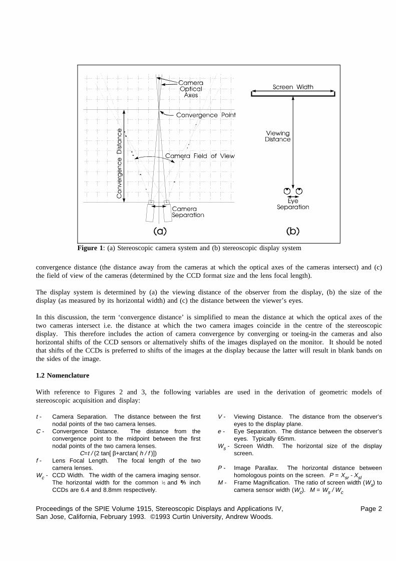
convergence distance (the distance away from the cameras at which the optical axes of the cameras intersect) and (c)
Figure 1: (a) Stereoscopic camera system and (b) stereoscopic display system
the field of view of the cameras (determined by the CCD format size and the lens focal length).
The display system is determined by (a) the viewing distance of the observer from the display, (b) the size of thedisplay (as measured by its horizontal width) and (c) the distance between the viewer’s eyes.
In this discussion, the term ‘convergence distance’ is simplified to mean the distance at which the optical axes of thetwo cameras intersect i.e. the distance at which the two camera images coincide in the centre of the stereoscopicdisplay. This therefore includes the action of camera convergence by converging or toeing-in the cameras and alsohorizontal shifts of the CCD sensors or alternatively shifts of the images displayed on the monitor. It should be notedthat shifts of the CCDs is preferred to shifts of the images at the display because the latter will result in blank bands onthe sides of the image.
1.2 Nomenclature
With reference to Figures 2 and 3, the following variables are used in the derivation of geometric models ofstereoscopic acquisition and display:
t - Camera Separation. The distance between the firstnodal points of the two camera lenses.
C - Convergence Distance. The distance from theconvergence point to the midpoint between the firstnodal points of the two camera lenses.
C=t / (2 tan[ β+arctan( h / f )])f - Lens Focal Length. The focal length of the two
camera lenses.Wc - CCD Width. The width of the camera imaging sensor.
The horizontal width for the common ½and inchCCDs are 6.4 and 8.8mm respectively.
V - Viewing Distance. The distance from the observer’seyes to the display plane.
e - Eye Separation. The distance between the observer’seyes. Typically 65mm.
Ws - Screen Width. The horizontal size of the displayscreen.
P - Image Parallax. The horizontal distance betweenhomologous points on the screen. P = Xsr - Xsl
M - Frame Magnification. The ratio of screen width (Ws) tocamera sensor width (Wc). M = Ws / Wc
Proceedings of the SPIE Volume 1915, Stereoscopic Displays and Applications IV, Page 2San Jose, California, February 1993. ©1993 Curtin University, Andrew Woods.

β - Camera Convergence Angle. In the toed-in cameramodel, this is the angle the cameras are each rotatedinwards from parallel to achieve convergence.
h - Sensor Axial Offset. In the parallel cameraconfiguration, this is the distance by which the centreof each imaging sensor (CCD) has been moved away(outwards) from the optical axis of the lens to achieveconvergence.
α - Camera Field of View. The horizontal angle of view ofthe camera.α=arctan[( Wc/2+h )/ f ] + arctan[( Wc/2- h)/ f ]
(Xo ,Yo ,Zo ) - The location of a point in object space (in frontof the cameras).
(Xi ,Yi ,Zi ) - The location of a point in image space (asstereoscopically viewed by the observer whendisplayed on the screen).
(Xcl ,Ycl ),(Xcr ,Ycr ) - The location of imaged points on the leftand right imaging sensors respectively.
(Xsl ,Ysl ),(Xsr ,Ysr ) - The location of left and right imagepoints on the screen.
Ys - Screen Y coordinate of a fused stereoscopic imagewhere vertical parallax is present. Ys =(Ysl +Ysr ) / 2
1.3 Geometry of stereoscopic video systems
The geometry of a stereoscopic video system can be determined by considering the imaging and display process asthree separate coordinate transforms: Firstly from X,Y,Z coordinates in object/camera space to X and Y positions on
Figure 2: Camera parameters for (a) toed-in camera configuration and (b) parallel camera configuration (Plan View)
Proceedings of the SPIE Volume 1915, Stereoscopic Displays and Applications IV, Page 3San Jose, California, February 1993. ©1993 Curtin University, Andrew Woods.

the two camera imaging sensors (CCDs), secondly from the two sets of CCD coordinates to X and Y positions of theleft and right images on the stereoscopic display, and thirdly to a set of X,Y,Z coordinates in image/viewer space.
This is summarised as follows: Object Space→ CCD Coordinates→ Screen Coordinates→ Image Space(Xo ,Yo , Zo ) (Xcl ,Ycl ),(Xcr ,Ycr ) (Xsl ,Ysl ),(Xsr ,Ysr ) (Xi ,Yi , Zi )
The first coordinate transform is shown in equations (1) to (4). The variables and coordinate conventions of thistransform are shown in Figure 2 except for the Y axis which for object space is centred at the midpoint between thefirst nodal points of the camera lenses and positive in the upward direction and for CCD coordinates is positive in thedownwards direction from the centre of the CCD.
(1) (2)
(3) (4)
The transformation from CCD coordinates to screen coordinates is achieved by multiplying by the screen magnificationfactor M:
(5) (6)
(7) (8)
The final transform from screen coordinates to image space coordinates is shown
Figure 3: Viewing parameters(Plan View)
in equations (9) to (11). The variables and coordinate conventions for thistransform are shown diagrammatically in Figure 3 except for the Y variableswhich are positive in the upwards direction from the centre of the screen.
(9)
(10)
(11)
Special mention needs to be made about the Y coordinate equation. Two valuescan be developed for the image space Y coordinate, one each from the left andright views,Ysl and Ysr, however, only one Y position is meaningful. Thereforea single value of screen Y position must be determined from these two values.The difference between screen Y coordinates is termed ‘vertical parallax’ and determines how easily the stereoscopicimage can be fused. If vertical parallax is small we useYs =(Ysl +Ysr )/2.
The overall coordinate transformation from object space coordinates to image space coordinates is:
(12)
Proceedings of the SPIE Volume 1915, Stereoscopic Displays and Applications IV, Page 4San Jose, California, February 1993. ©1993 Curtin University, Andrew Woods.

(13)
(14)
These equations apply to both the parallel camera and the toed-in camera configurations. Significant simplificationscan be made for a parallel camera configuration. It should also be noted that these equations do not contain any smallangle approximations. It has been found that small angle approximations can obscure some stereoscopic distortions2,3.
1.4 Visualisation of stereoscopic video system geometry
In order to illustrate the
Figure 4: Coordinate transformation from Object Space to Image Space(for C = 0.9m, f = 6.5mm,t = 75mm,V = 0.9m,e = 65mm,Ws = 300mm).
results of the above equations,a computer program wasdeveloped to generate plotswhich display the coordinatetransformation from objectspace to image space. Anexample of one of these plotsis shown in Figure 4. Thisplot shows the way in whichthe object space in front of thecamera system (in the XZplane) is transformed to thedisplay system (image space).The grid pattern demonstrateshow a rectilinear grid (of 10cm squares) in front of the camera system has been distorted upon display. The twocircles represent the viewer’s eyes and the bold line is the display. The grid pattern extends to 3m away from thecameras. The curve furthest from the eyes indicates where infinity from the cameras will be displayed on the monitor.The grid pattern is not displayed past 3m to infinity due to its increasing density.
1.5 Variation of parameters.
The manipulation of the three camera configuration parameters and the three display configuration parameters areshown diagrammatically in Figures 5 and 6. These figures show how the image display geometry of a predeterminedcamera and display configuration is affected by changes of configuration parameters.
2. STEREOSCOPIC DISTORTIONS
Stereoscopic distortions are ways in which a stereoscopic image of a scene differs from actually viewing the scenedirectly. There are a number of different types of image distortions in stereoscopic video systems. This chapter willdiscuss various types of image distortions including outlining their origins and their effects on a viewer’s perception ofa scene.
Proceedings of the SPIE Volume 1915, Stereoscopic Displays and Applications IV, Page 5San Jose, California, February 1993. ©1993 Curtin University, Andrew Woods.
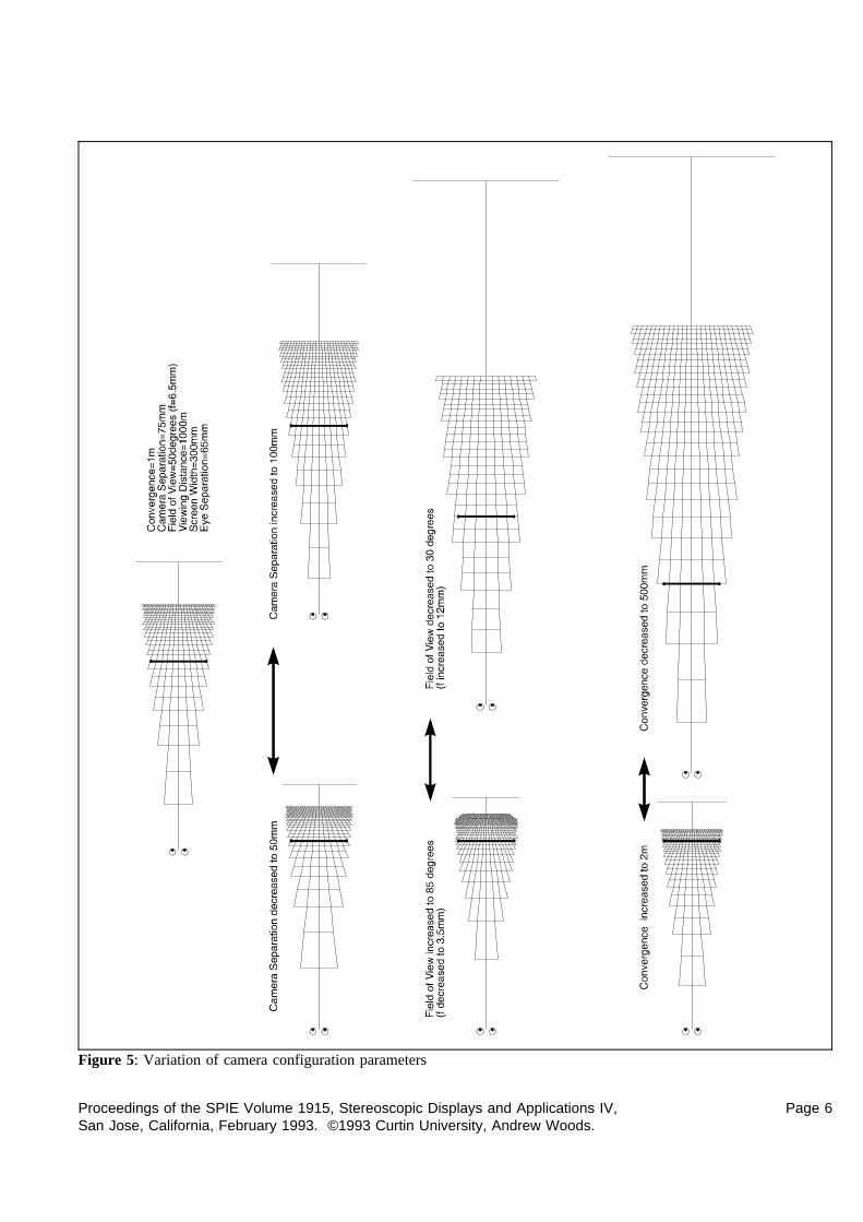
Figure 5: Variation of camera configuration parameters
Proceedings of the SPIE Volume 1915, Stereoscopic Displays and Applications IV, Page 6San Jose, California, February 1993. ©1993 Curtin University, Andrew Woods.

Figure 6: Variation of display configuration parameters
Proceedings of the SPIE Volume 1915, Stereoscopic Displays and Applications IV, Page 7San Jose, California, February 1993. ©1993 Curtin University, Andrew Woods.

2.1 Depth plane curvature
Figure 7: 3D maps of (a) toed-in cameras (b) parallel cameras (c) sheardistortion and (d) plot of image distance versus object distance.
As mentioned earlier, the same convergencedistance can be achieved either by theparallel camera configuration (with axialoffset of the imaging sensor) or the toed-incamera configuration (where the cameras areangled in). Figures 7(a) and (b) show thesame convergence distance achieved by firstthe toed-in camera configuration andsecondly by the parallel cameraconfiguration. It can be seen quite clearlyfrom these plots that the toed-in cameraconfiguration results in a curvature of thedepth planes. This will result in objects atthe corners of the image appearing furtheraway from the viewer than objects at thecentre of the image. In contrast the parallelcamera configuration results in depth planeswhich are parallel to the surface of themonitor. Depth plane curvature is closelylinked with keystone distortion which isdiscussed later.
The depth plane curvature illustrated herecould lead to wrongly perceived relativeobject distances on the display and alsodisturbing image motions during panning ofthe camera system.
2.2 Depth non-linearity
Figure 7(d) shows a plot illustrating therelationship between object distance awayfrom the camera system and image distanceaway from the eyes for the systemconfigurations of Figures(a) and (b). Thegraph shows the convergence and viewing distances at 1m as dotted lines. It can be seen from this graph, Figure 7(d),and also the 3D maps of Figure 7(a) and (b) that the depth is stretched between the viewer and the monitor andcompressed between the monitor and infinity.
The non-linearity of depth on the display can lead to wrongly perceived depth on the monitor and if the camera systemis in motion it can lead to false estimations of velocity4. An example of this is the case of a stereoscopic camerasystem on a vehicle approaching a structure at a constant velocity. At first the vehicle will appear to be approachingthe structure rather slowly but once the structure comes closer to the camera than the convergence distance, the vehiclewill appear to accelerate. This could lead to incorrect actions in the control of the vehicle.
It has already been shown2,5 that a linear relationship between image depth and object depth can only be obtained byconfiguring the stereoscopic video system such that object infinity is displayed at image infinity on the stereoscopicdisplay.
Proceedings of the SPIE Volume 1915, Stereoscopic Displays and Applications IV, Page 8San Jose, California, February 1993. ©1993 Curtin University, Andrew Woods.

2.3 Shear distortion
A disadvantage of binocular stereoscopic displays is that the stereoscopic image appears to follow the observer whenthe observer changes viewing position. Change in the viewing distance has already been considered above. Asideways movement of the observer leads to a different type of distortion which we have called ‘shear distortion’. Ascan be seen in Figure 7(c), a sideways movement of the observer results in a sideways shear of the stereoscopic imageabout the surface of the monitor - images out of the monitor will appear to shear in the direction of the observer andimages behind the surface of the monitor shear in the opposite direction.
Shear distortion can result in wrongly perceived relative object distances. In Figure 7(c), images on the left wouldfalsely appear closer than images on the right. Another result of shear distortion (as well as a change in viewingdistance) is that observer motion will lead to false perception of motion in the image. For example if the operator of avehicle moved his head while the vehicle was stationary, image motion would be seen where the is none. This effectis most noticeable for images which are furthest away from the stereoscopic display surface.
2.4 Depth and size magnification
An analysis of image magnification or image scaling reveals that there can be a mismatch between depth magnificationand size (width and height) magnification. This is particularly so when there is a non-linear relationship betweenimage and object depth. A mismatch between depth and size magnification can lead to an image appearing flat orconversely stretched. We have not considered this effect in great detail in our research, however, an analysis of depthand size magnification is contained in references 2 and 5.
2.5 Keystone distortion
Figure 8: Vertical parallax caused by keystonedistortion
A well know effect of the toed-in camera configuration iskeystone distortion. Keystone distortion causes verticalparallax in the stereoscopic image due to the imaging sensorsof the two cameras being located in different planes. Theeffect of keystone distortion upon the display of a gridlocated at the camera convergence distance is shown inFigure 8. In one of the cameras, the image of the gridappears larger at one side than the other. In the othercamera, this effect is reversed. This results in a verticaldifference between homologous point which is called verticalparallax. The amount of vertical parallax is greatest in thecorners of the image and increases with increased cameraseparation, decreased convergence distance and decreasedfocal length. In this example, a lens with a focal length of3.5mm (C=1m and t=75mm) would exhibit vertical parallaxof 8.2mm in the corner of the screen on a 16" diagonal monitor. It can also be seen from this diagram that horizontalparallax is also induced. This is the source of the depth plane curvature mentioned earlier. The parallel cameraconfiguration does not exhibit keystone distortion.
2.6 Lens distortion
Lens radial distortion, often called pin-cushion or barrel distortion, is another source of image distortion and inducedvertical parallax. Lens radial distortion is caused by the use of spherical lens elements, resulting in the lens havingdifferent focal lengths at various radial distances from the centre of the lens. Increasing focal length from the centre ofthe lens is called pin-cushion distortion and the reverse is called barrel distortion. Figure 9 shows the barrel distortionof a Canon 3.5mm lens mounted on a½" CCD camera. The grid is an actual image from a camera and lensphotographing a 5cm spaced grid located 320mm away from the lens. It can be seen from this figure that the
Proceedings of the SPIE Volume 1915, Stereoscopic Displays and Applications IV, Page 9San Jose, California, February 1993. ©1993 Curtin University, Andrew Woods.
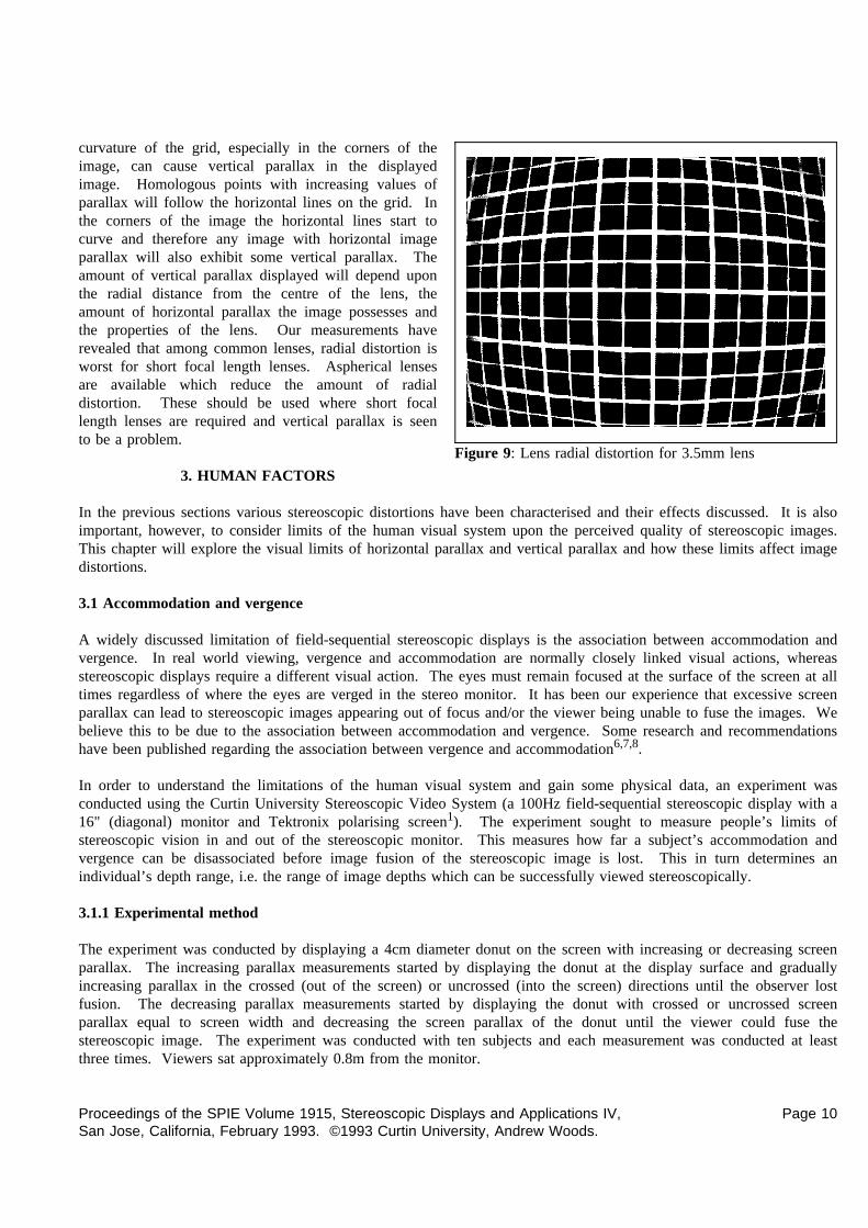
curvature of the grid, especially in the corners of the
Figure 9: Lens radial distortion for 3.5mm lens
image, can cause vertical parallax in the displayedimage. Homologous points with increasing values ofparallax will follow the horizontal lines on the grid. Inthe corners of the image the horizontal lines start tocurve and therefore any image with horizontal imageparallax will also exhibit some vertical parallax. Theamount of vertical parallax displayed will depend uponthe radial distance from the centre of the lens, theamount of horizontal parallax the image possesses andthe properties of the lens. Our measurements haverevealed that among common lenses, radial distortion isworst for short focal length lenses. Aspherical lensesare available which reduce the amount of radialdistortion. These should be used where short focallength lenses are required and vertical parallax is seento be a problem.
3. HUMAN FACTORS
In the previous sections various stereoscopic distortions have been characterised and their effects discussed. It is alsoimportant, however, to consider limits of the human visual system upon the perceived quality of stereoscopic images.This chapter will explore the visual limits of horizontal parallax and vertical parallax and how these limits affect imagedistortions.
3.1 Accommodation and vergence
A widely discussed limitation of field-sequential stereoscopic displays is the association between accommodation andvergence. In real world viewing, vergence and accommodation are normally closely linked visual actions, whereasstereoscopic displays require a different visual action. The eyes must remain focused at the surface of the screen at alltimes regardless of where the eyes are verged in the stereo monitor. It has been our experience that excessive screenparallax can lead to stereoscopic images appearing out of focus and/or the viewer being unable to fuse the images. Webelieve this to be due to the association between accommodation and vergence. Some research and recommendationshave been published regarding the association between vergence and accommodation6,7,8.
In order to understand the limitations of the human visual system and gain some physical data, an experiment wasconducted using the Curtin University Stereoscopic Video System (a 100Hz field-sequential stereoscopic display with a16" (diagonal) monitor and Tektronix polarising screen1). The experiment sought to measure people’s limits ofstereoscopic vision in and out of the stereoscopic monitor. This measures how far a subject’s accommodation andvergence can be disassociated before image fusion of the stereoscopic image is lost. This in turn determines anindividual’s depth range, i.e. the range of image depths which can be successfully viewed stereoscopically.
3.1.1 Experimental method
The experiment was conducted by displaying a 4cm diameter donut on the screen with increasing or decreasing screenparallax. The increasing parallax measurements started by displaying the donut at the display surface and graduallyincreasing parallax in the crossed (out of the screen) or uncrossed (into the screen) directions until the observer lostfusion. The decreasing parallax measurements started by displaying the donut with crossed or uncrossed screenparallax equal to screen width and decreasing the screen parallax of the donut until the viewer could fuse thestereoscopic image. The experiment was conducted with ten subjects and each measurement was conducted at leastthree times. Viewers sat approximately 0.8m from the monitor.
Proceedings of the SPIE Volume 1915, Stereoscopic Displays and Applications IV, Page 10San Jose, California, February 1993. ©1993 Curtin University, Andrew Woods.
3.1.2 Results
Figure 10: Experimental results of depth range limit
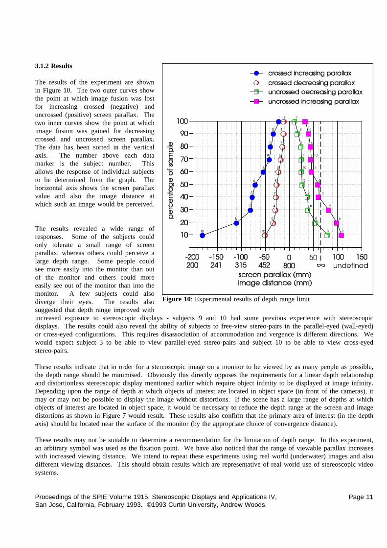
The results of the experiment are shownin Figure 10. The two outer curves showthe point at which image fusion was lostfor increasing crossed (negative) anduncrossed (positive) screen parallax. Thetwo inner curves show the point at whichimage fusion was gained for decreasingcrossed and uncrossed screen parallax.The data has been sorted in the verticalaxis. The number above each datamarker is the subject number. Thisallows the response of individual subjectsto be determined from the graph. Thehorizontal axis shows the screen parallaxvalue and also the image distance atwhich such an image would be perceived.
The results revealed a wide range ofresponses. Some of the subjects couldonly tolerate a small range of screenparallax, whereas others could perceive alarge depth range. Some people couldsee more easily into the monitor than outof the monitor and others could moreeasily see out of the monitor than into themonitor. A few subjects could alsodiverge their eyes. The results alsosuggested that depth range improved withincreased exposure to stereoscopic displays - subjects 9 and 10 had some previous experience with stereoscopicdisplays. The results could also reveal the ability of subjects to free-view stereo-pairs in the parallel-eyed (wall-eyed)or cross-eyed configurations. This requires disassociation of accommodation and vergence is different directions. Wewould expect subject 3 to be able to view parallel-eyed stereo-pairs and subject 10 to be able to view cross-eyedstereo-pairs.
These results indicate that in order for a stereoscopic image on a monitor to be viewed by as many people as possible,the depth range should be minimised. Obviously this directly opposes the requirements for a linear depth relationshipand distortionless stereoscopic display mentioned earlier which require object infinity to be displayed at image infinity.Depending upon the range of depth at which objects of interest are located in object space (in front of the cameras), itmay or may not be possible to display the image without distortions. If the scene has a large range of depths at whichobjects of interest are located in object space, it would be necessary to reduce the depth range at the screen and imagedistortions as shown in Figure 7 would result. These results also confirm that the primary area of interest (in the depthaxis) should be located near the surface of the monitor (by the appropriate choice of convergence distance).
These results may not be suitable to determine a recommendation for the limitation of depth range. In this experiment,an arbitrary symbol was used as the fixation point. We have also noticed that the range of viewable parallax increaseswith increased viewing distance. We intend to repeat these experiments using real world (underwater) images and alsodifferent viewing distances. This should obtain results which are representative of real world use of stereoscopic videosystems.
Proceedings of the SPIE Volume 1915, Stereoscopic Displays and Applications IV, Page 11San Jose, California, February 1993. ©1993 Curtin University, Andrew Woods.
3.2 Vertical parallax
In the experiment above, visual limits of vertical parallax were also measured for increasing vertical parallax. Theresults indicated that homologous points should have less than 7mm of vertical parallax for image fusion to bepossible. The subjects also reported that eye strain was apparent at higher values of vertical parallax. Needless to say,vertical parallax should be reduced as much as possible to produce an easily viewed image. "With the notableexception of glitter, sparkle, or lustre, the only desirable asymmetries in a stereoscopic system of photography andprojection are the asymmetries of horizontal parallax."9
4. DISCUSSION AND CONCLUSION
The main recommendation of this study is that the parallel camera configuration is used in preference to the toed-in(converged) camera configuration. This will eliminate keystone distortion and depth plane curvature. Comment shouldbe made about the practicality of obtaining such an alignment. In the configuration of Figure 5 the difference betweenthe alignment of the parallel & toed-in cameras configurations is 2.1° of rotation per camera and 0.24mm of axialoffset relative to the lens per imaging sensor. Obviously such small differences need accurate means of alignment.Indeed, it has been our experience that off-the-shelf cameras do not provide sufficient control over CCD positionrelative to the lens. Some video cameras and lens combinations have so much freedom in their mounts that up to 2mmmovement of the lens relative to the CCD is possible. If such a camera system was subject to vibration, the alignmentof the system may be subject to continual change. In our experience, off-the-shelf cameras need to be modified toprovide such control.
Lens radial distortion can be a significant source of vertical parallax, particularly when wide angle lenses are used onthe camera system. When vertical parallax due to lens radial distortion is seen to be a problem, lenses with low radialdistortion should be chosen. Aspherical lenses may meet this requirement.
As mentioned in Section 3.1, the association between accommodation and vergence places a limit upon thedepth/parallax range of a stereoscopic image. This in turn means that a linear relationship between image and objectdistance may not be achievable. This will depend upon the depth content of the subject matter in front of the camerasystem and also the ability of the observers to whom the stereoscopic images are to be displayed. If the system is onlyto be used by trained observers, a larger depth range may be possible which will reduce depth non-linearity.
As mentioned earlier, the material in this paper was developed for a field-sequential stereoscopic video system. Theseprinciples are also directly applicable to other types of stereoscopic displays such as anaglyphic displays, polarisedprojected displays, half silvered mirror displays and some lenticular displays. These concepts are not directlyapplicable to head mounted displays, however, the techniques described could be adapted to head mounted displaygeometry.
It has been shown that there can be large range of distortions involved in the display of stereoscopic images onstereoscopic displays. It has also been shown that it is possible to eliminate some of these distortions by theappropriate choice of system parameters. There are some distortions, however, which cannot be avoided due to thenature of human vision and limitations of current stereoscopic video display techniques.
5. ACKNOWLEDGMENTS
The authors wish to thank Woodside Offshore Petroleum for their support of this project. We would also like to thankDavid Drascic for participating in many discussions during the process of this work.
Proceedings of the SPIE Volume 1915, Stereoscopic Displays and Applications IV, Page 12San Jose, California, February 1993. ©1993 Curtin University, Andrew Woods.
6. REFERENCES
1. A. Woods, T. Docherty and R. Koch, "The use of Flicker-Free Television Products for Stereoscopic Displays andApplications," Stereoscopic Displays and Applications II, J. Merritt, S. Fisher, Editors, Proc. SPIE 1457, pp. 322-326, 1991.
2. D. Diner, "A New Definition of Orthostereopsis for 3-D Television," IEEE International Conference on Systems,Man and Cybernetics, pp. 1053-1058, October 1991.
3. R. Spottiswoode and N. Spottiswoode, The Theory of Stereoscopic Transmission and its Application to the MotionPicture, University of California Press, Berkeley, 1953.
4. D. Diner, "Danger of Collisions for Tele-Operated Navigation due to Erroneous Perceived Depth Accelerations in3-D Television," Annual Meeting of the American Nuclear Society, 1991.
5. C. Smith, "3-D or not 3-D?" New Scientist, Vol.102 #1407, pp. 40-44, April 1984.
6. Y. Yeh and L. Silverstein, "Using Electronic Stereoscopic Color Displays: Limits of Fusion and DepthDiscrimination," Three Dimensional Visualisation and Display Technologies, W. Robbins, S. Fisher, Editors, Proc.SPIE 1083, pp. 196-204, 1989.
7. L. Hodges, "Basic Principles of Stereographic Software Development," Stereoscopic Displays and Applications II, J.Merritt, S. Fisher, Editors, Proc. SPIE 1457, pp. 9-17, 1991.
8. R. Akka, "Automatic Software Control of Display Parameters for Stereoscopic Graphic Images," StereoscopicDisplays and Applications III, J. Merritt, S. Fisher, Proc. SPIE 1669, pp. 31-38, 1992.
9. L. Lipton, Foundations of the Stereoscopic Cinema, Van Nostrand Reinhold Company Inc., New York, 1982.
Copyright on this document is retained by Curtin University. This document is not public domain.Permission is hereby given to reprint this paper on a non-profit basis for scholarly purposes provided the document isunaltered and this notice is intact. This paper may not be reprinted on a large scale basis or in an anthology withoutprior written permission. If you wish to reprint this paper on this basis, please contact the primary author at theaddress shown on the first page of this document.
Proceedings of the SPIE Volume 1915, Stereoscopic Displays and Applications IV, Page 13San Jose, California, February 1993. ©1993 Curtin University, Andrew Woods.


![New TUC Zoom Video-Conferencing System · 2020. 6. 21. · TUC Zoom Video-Conferencing System Οηός ια Σμμέχονς Έκοση 3.1 [21.06.2020] Εισαγωγή Ενεργοποίηση](https://static.fdocument.org/doc/165x107/6045e7137f33c62160287401/new-tuc-zoom-video-conferencing-system-2020-6-21-tuc-zoom-video-conferencing.jpg)