Hydraulics of pipelines -...
23
Hydraulics of pipelines
Transcript of Hydraulics of pipelines -...
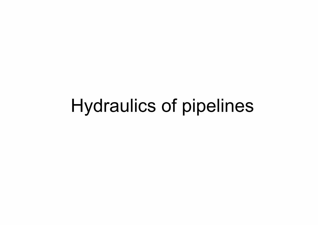
Hydraulics of pipelines
K 141 HYAE Hydraulics of pipelines 1
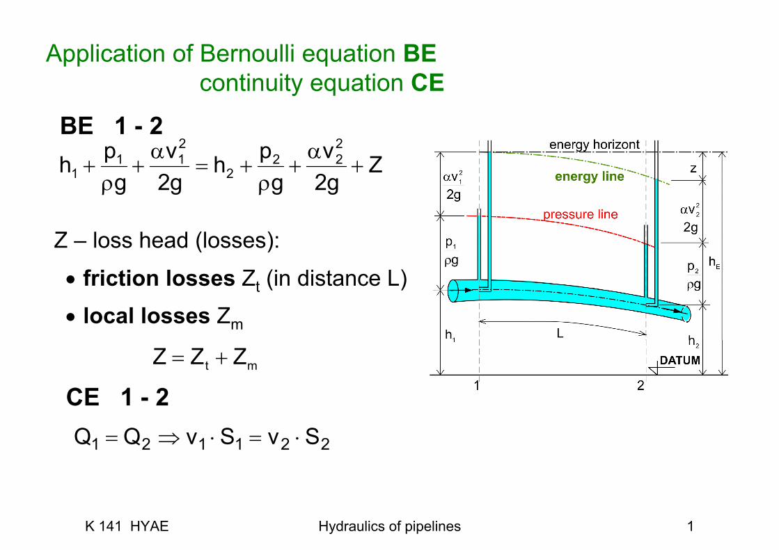
Application of Bernoulli equation BEcontinuity equation CE
Zgv
gph
gv
gph +
α+
ρ+=
α+
ρ+
22
222
2
211
1
Z – loss head (losses):
• friction losses Zt (in distance L)
• local losses Zm
mt ZZZ +=
BE 1 - 2
CE 1 - 2
221121 SvSvQQ ⋅=⋅⇒=
K 141 HYAE Hydraulics of pipelines 2
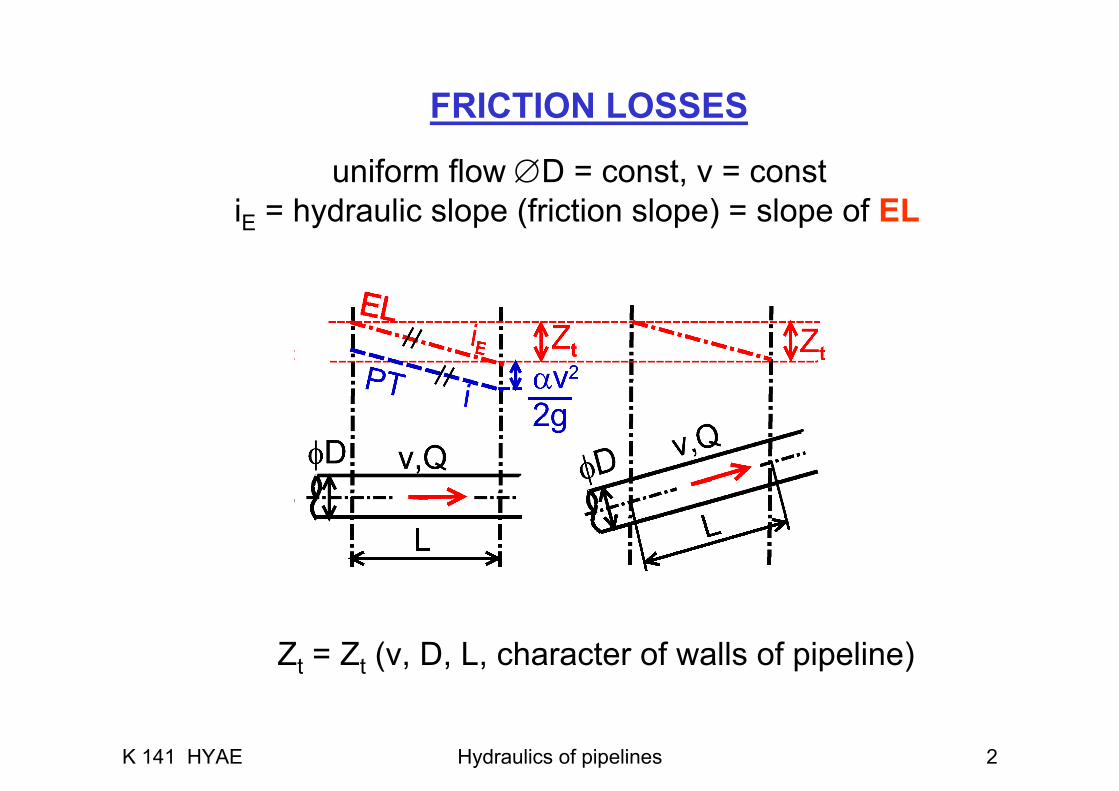
FRICTION LOSSES
uniform flow ∅D = const, v = constiE = hydraulic slope (friction slope) = slope of EL
Zt = Zt (v, D, L, character of walls of pipeline)
K 141 HYAE Hydraulics of pipelines 3
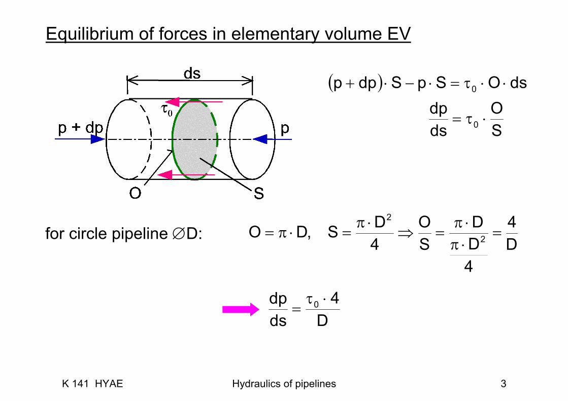
Equilibrium of forces in elementary volume EV
( ) dsOSpSdpp 0 ⋅⋅τ=⋅−⋅+
SO
dsdp
0 ⋅τ=
for circle pipeline ∅D:D4
4DD
SO
4DS,DO 2
2
=⋅π⋅π
=⇒⋅π
=⋅π=
D4
dsdp 0 ⋅τ
=
K 141 HYAE Hydraulics of pipelines 4
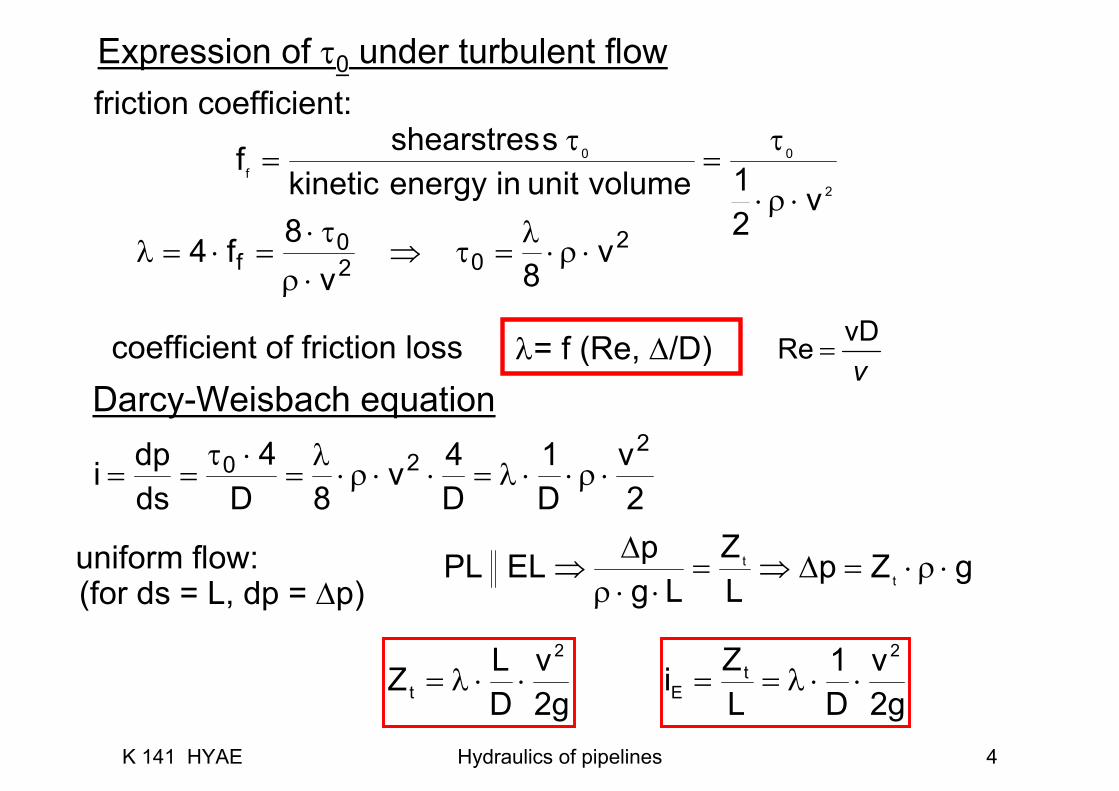
Darcy-Weisbach equation
2v
D1
D4v
8D4
dsdpi
220 ⋅ρ⋅⋅λ=⋅⋅ρ⋅
λ=
⋅τ==
uniform flow: gZpLZ
LgpELPL t
t ⋅ρ⋅=Δ⇒=⋅⋅ρ
Δ⇒
g2v
DLZ
2
t ⋅⋅λ=
(for ds = L, dp = Δp)
g2v
D1
LZi
2t
E ⋅⋅λ==
Expression of τ0 under turbulent flow
2
00f
v21volumeunitinenergykinetic
sshearstresf⋅ρ⋅
τ=
τ=
202
0f v
8v8f4 ⋅ρ⋅
λ=τ⇒
⋅ρτ⋅
=⋅=λ
coefficient of friction loss λ= f (Re, Δ/D)ν
vDRe =
friction coefficient:
K 141 HYAE Hydraulics of pipelines 5
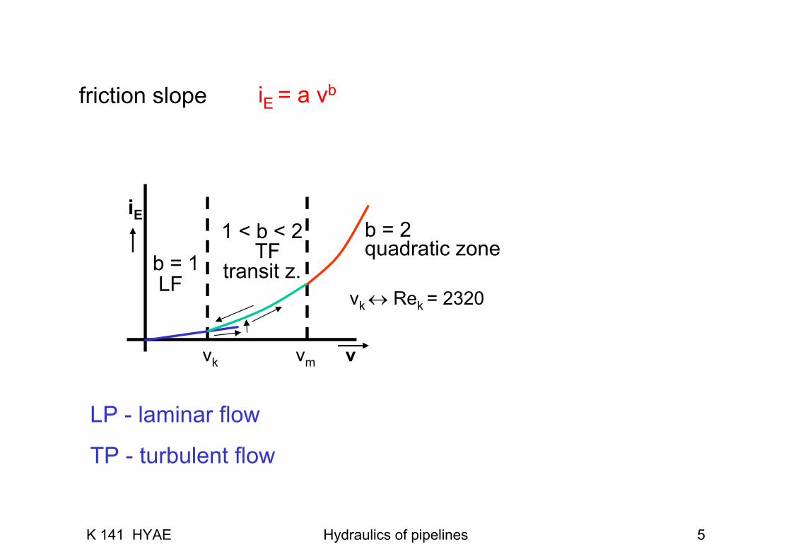
iE = a vbfriction slope
b = 1LF
1 < b < 2TF
transit z.
b = 2quadratic zone
iE
vk ↔ Rek = 2320
vmvk v
LP - laminar flow
TP - turbulent flow
K 141 HYAE Hydraulics of pipelines 6
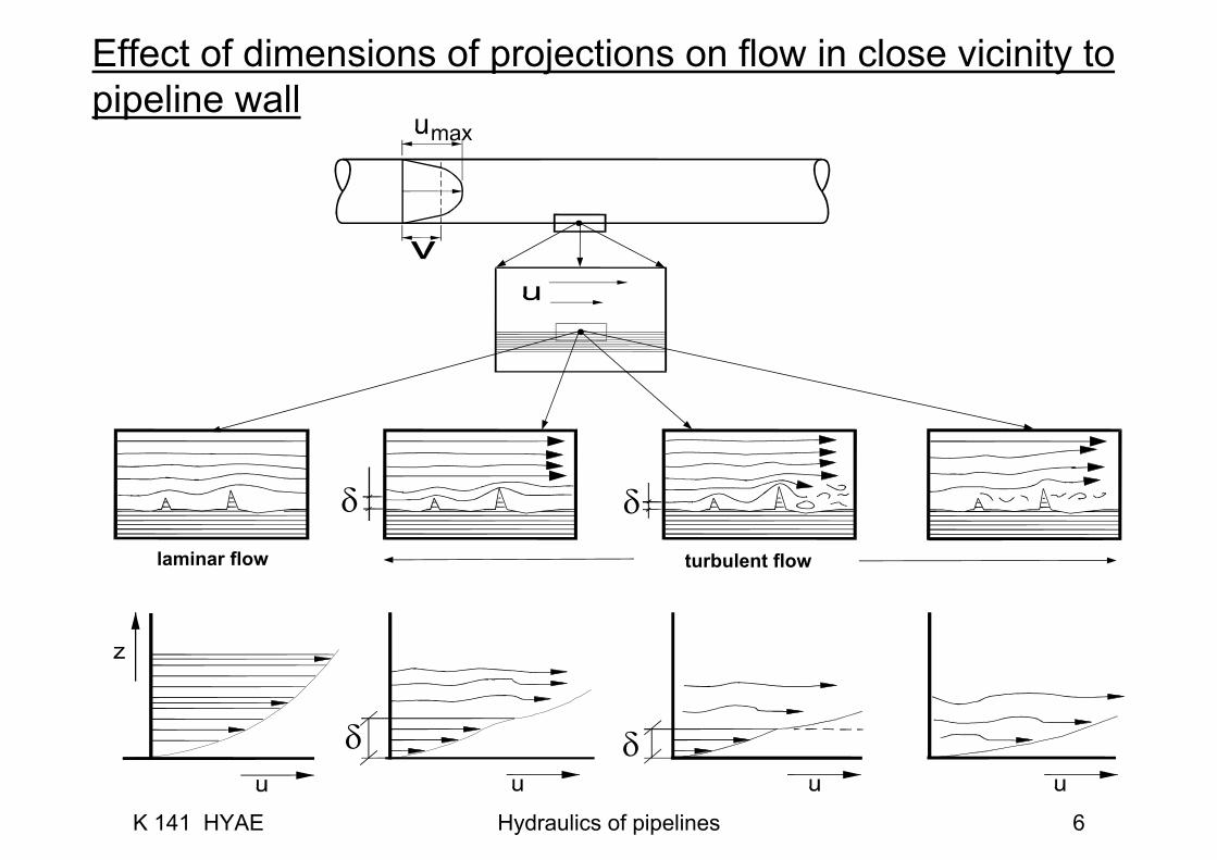
Effect of dimensions of projections on flow in close vicinity topipeline wall
turbulent flow
δ δ
δδ
laminar flow
K 141 HYAE Hydraulics of pipelines 7
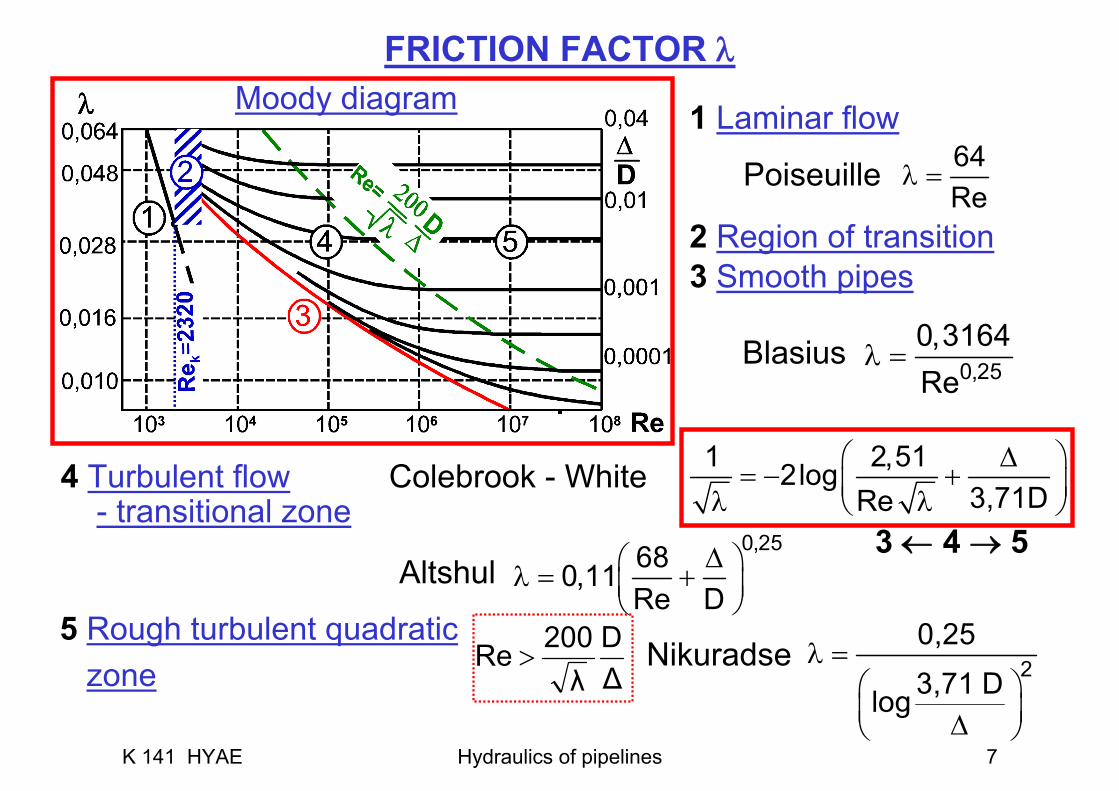
FRICTION FACTOR λMoody diagram 1 Laminar flow
Poiseuille
2 Region of transition3 Smooth pipes
4 Turbulent flow Colebrook - White- transitional zone
20,25
3,71 Dlogλ =
⎛ ⎞⎜ ⎟Δ⎝ ⎠
0,25680,11Re D
Δ⎛ ⎞λ = +⎜ ⎟⎝ ⎠
1 2,512log3,71DRe
⎛ ⎞Δ= − +⎜ ⎟λ λ⎝ ⎠
64Re
λ =
0,250,3164Re
λ =
3 ← 4 → 5Altshul
NikuradseΔD
λ200Re >
5 Rough turbulent quadraticzone
Blasius
K 141 HYAE Hydraulics of pipelines 8
Notes:
- tap water T = 12°C → ν = 1,24.10-6 m2s-1
- hydraulic roughness Δ = 0,01 mm ÷1 mm
- recommended velocity for water pipeline 0,5 ÷ 1,5 ms-1
tables
K 141 HYAE Hydraulics of pipelines 9
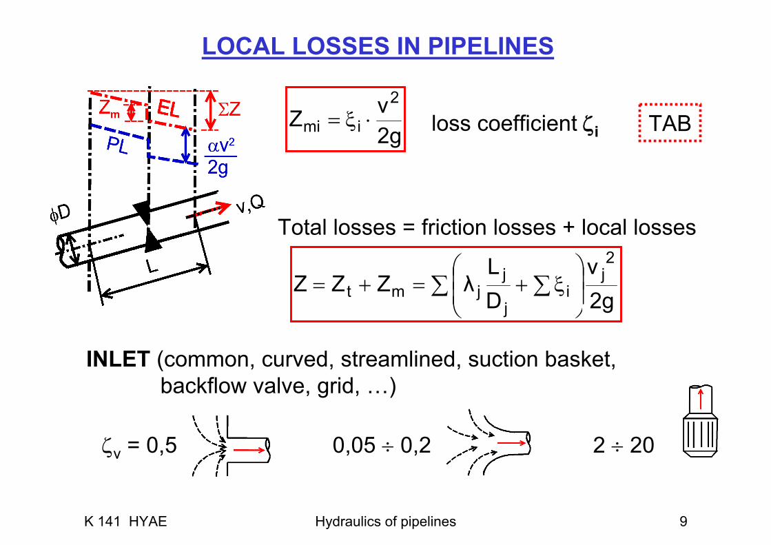
LOCAL LOSSES IN PIPELINES
loss coefficient ζi
INLET (common, curved, streamlined, suction basket,backflow valve, grid, …)
ζv = 0,5 0,05 ÷ 0,2 2 ÷ 20
TAB
Total losses = friction losses + local losses
g2vZ
2
imi ⋅ξ=
∑ ∑ ⎟⎟⎠
⎞⎜⎜⎝
⎛ξ+=+=
2gv
DL
λZ2j
ij
jjmt ZZ
K 141 HYAE Hydraulics of pipelines 10
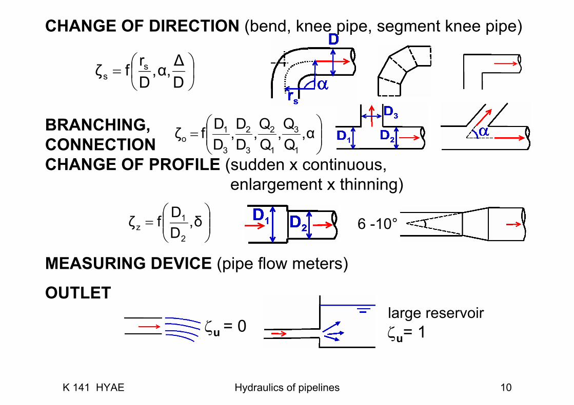
CHANGE OF DIRECTION (bend, knee pipe, segment knee pipe)
BRANCHING,CONNECTIONCHANGE OF PROFILE (sudden x continuous,
enlargement x thinning)
MEASURING DEVICE (pipe flow meters)
OUTLET
6 -10°
ζu = 0large reservoirζu= 1
⎟⎠⎞
⎜⎝⎛=
DΔα,,
Drfζ s
s
⎟⎟⎠
⎞⎜⎜⎝
⎛= δ,
DDfζ
2
1z
⎟⎟⎠
⎞⎜⎜⎝
⎛= α,
QQ,
QQ,
DD,
DDfζ
1
3
1
2
3
2
3
1o
K 141 HYAE Hydraulics of pipelines 11
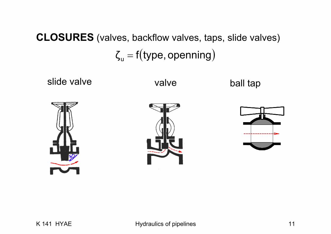
slide valve valve
CLOSURES (valves, backflow valves, taps, slide valves)
( )openningtype,fζu =
ball tap
K 141 HYAE Hydraulics of pipelines 12
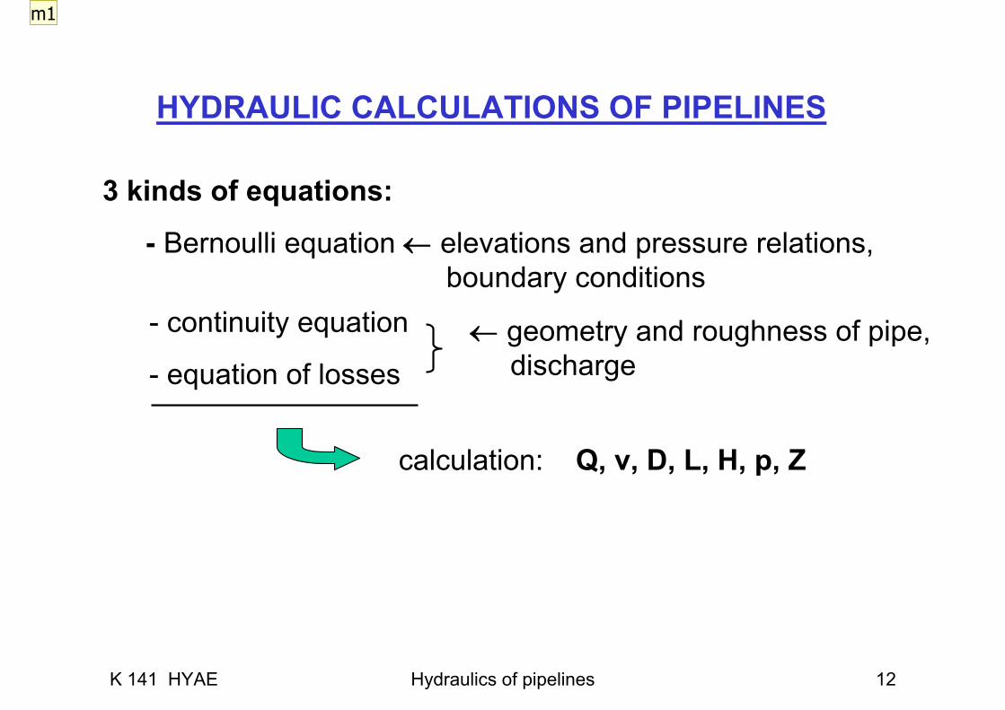
HYDRAULIC CALCULATIONS OF PIPELINES
3 kinds of equations:
← geometry and roughness of pipe,discharge
- Bernoulli equation ← elevations and pressure relations,boundary conditions
calculation: Q, v, D, L, H, p, Z
- continuity equation
- equation of losses
m1

Slide 13
m1 maresovai; 24.3.2006
K 141 HYAE Hydraulics of pipelines 13
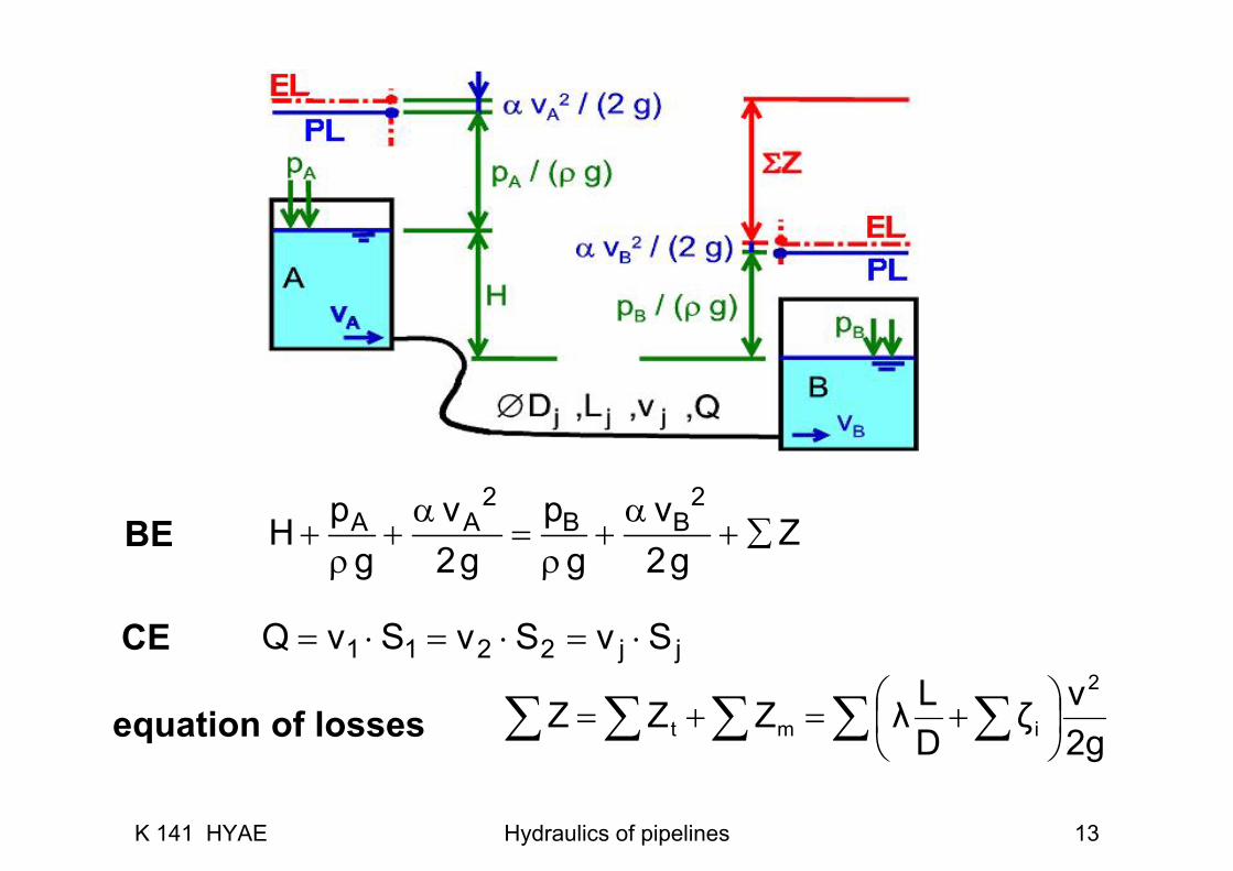
2 2A A B Bp v p vH Zg 2g g 2g
α α+ + = + + ∑
ρ ρ
∑ ∑ ∑ ∑ ∑ ⎟⎠⎞
⎜⎝⎛ +=+=
2gvζ
DLλZZZ
2
imt
BE
CE jj2211 SvSvSvQ ⋅=⋅=⋅=
equation of losses
K 141 HYAE Hydraulics of pipelines 14
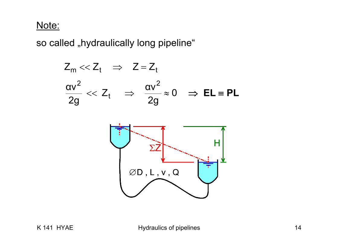
⇒ EL ≡ PL
Note:
so called „hydraulically long pipeline“
02gαvZ
2gαv 2
t
2≈⇒<<
ttm ZZZ =⇒<< Z
K 141 HYAE Hydraulics of pipelines 15
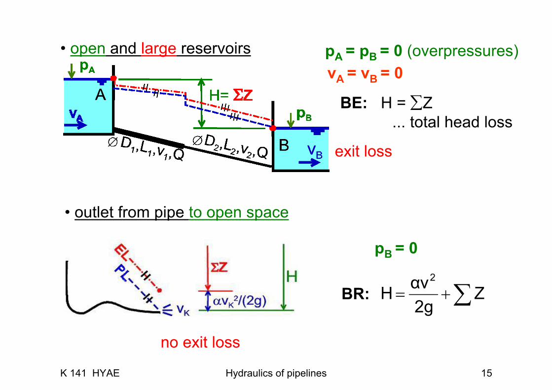
• open and large reservoirs
• outlet from pipe to open space
BE: H = ∑Z... total head loss
BR:
exit loss
no exit loss
pB = 0
pA = pB = 0 (overpressures)vA = vB = 0
∑+= Z2gαvH
2
K 141 HYAE Hydraulics of pipelines 16
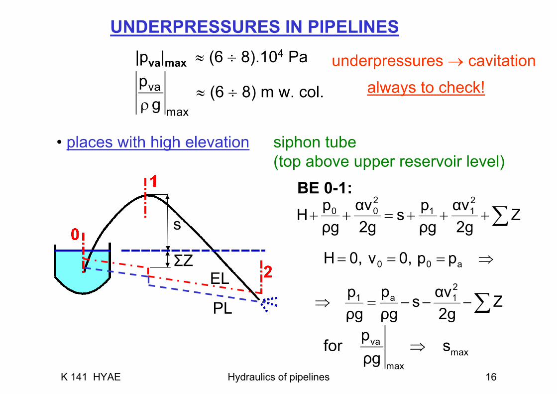
UNDERPRESSURES IN PIPELINES
always to check!
|pva|max ≈ (6 ÷ 8).104 Pa
≈ (6 ÷ 8) m w. col.va
max
pgρ
underpressures → cavitation
• places with high elevation siphon tube(top above upper reservoir level)
BE 0-1:
s
ΣZEL
PL ∑
∑
−−−=⇒
⇒===
+++=++
Z2gαvs
ρgp
ρgp
pp0,v0,H
Z2gαv
ρgps
2gαv
ρgpH
21a1
a00
211
200
vamax
max
pfor sρg
⇒
K 141 HYAE Hydraulics of pipelines 17
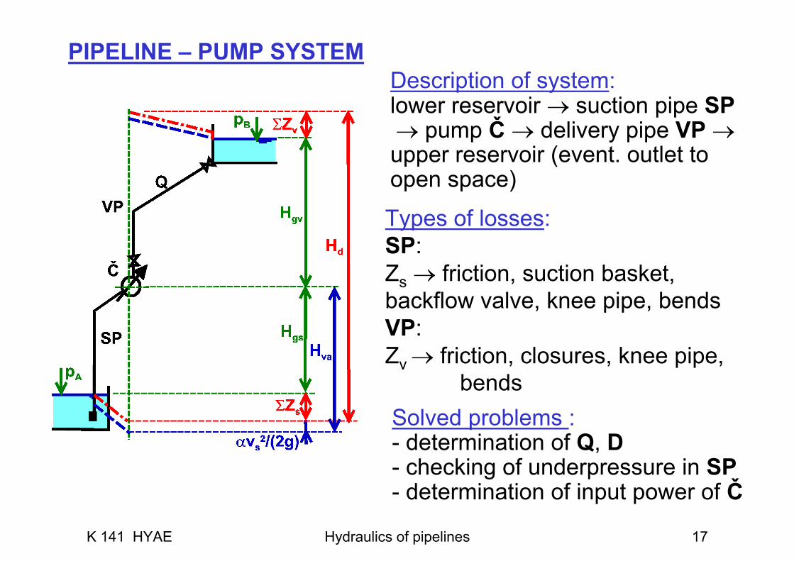
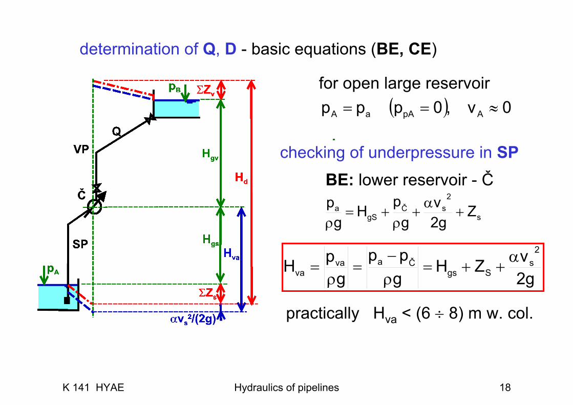
Description of system:lower reservoir → suction pipe SP → pump Č → delivery pipe VP →upper reservoir (event. outlet to open space)
Solved problems :- determination of Q, D- checking of underpressure in SP- determination of input power of Č
Types of losses:SP:Zs → friction, suction basket, backflow valve, knee pipe, bendsVP:Zv → friction, closures, knee pipe,
bends
PIPELINE – PUMP SYSTEM
K 141 HYAE Hydraulics of pipelines 18
g2v
gpp
gp 2
sČava α++=ρ−
=ρ
= Sgsva ZHH
p A
BE: lower reservoir - Č
s
2sČ
gSa Z
g2v
gp
Hg
p +α+ρ
+=ρ
for open large reservoir( ) 0v,0pp ApA ≈== aAp
practically Hva < (6 ÷ 8) m w. col.
determination of Q, D - basic equations (BE, CE)
checking of underpressure in SP
K 141 HYAE Hydraulics of pipelines 19
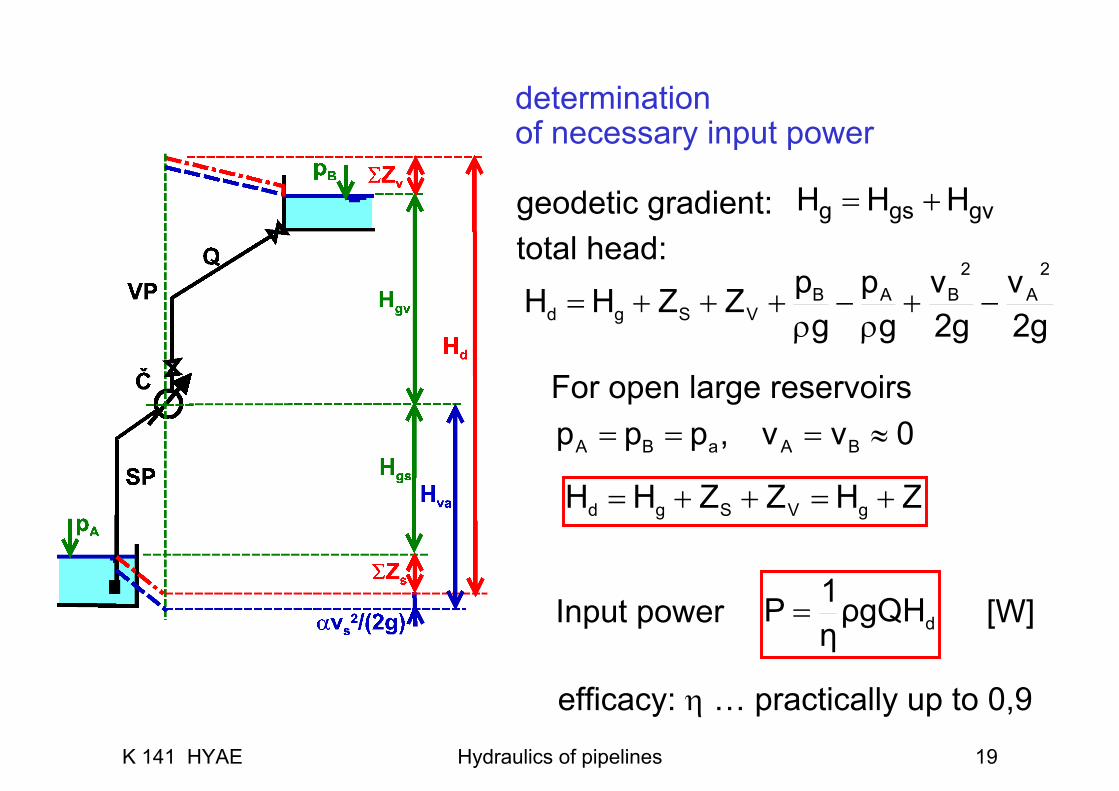
geodetic gradient:total head:
g2v
g2v
gp
gp 2
A2
BAB −+ρ
−ρ
+++= VSgd ZZHH
Z+=++= gVSgd HZZHH
gvgsg HHH +=
For open large reservoirs0vv,pp BA ≈=== aBAp
Input power [W]
efficacy: η … practically up to 0,9
dρgQHη1P =
determination of necessary input power
K 141 HYAE Hydraulics of pipelines 20
VA
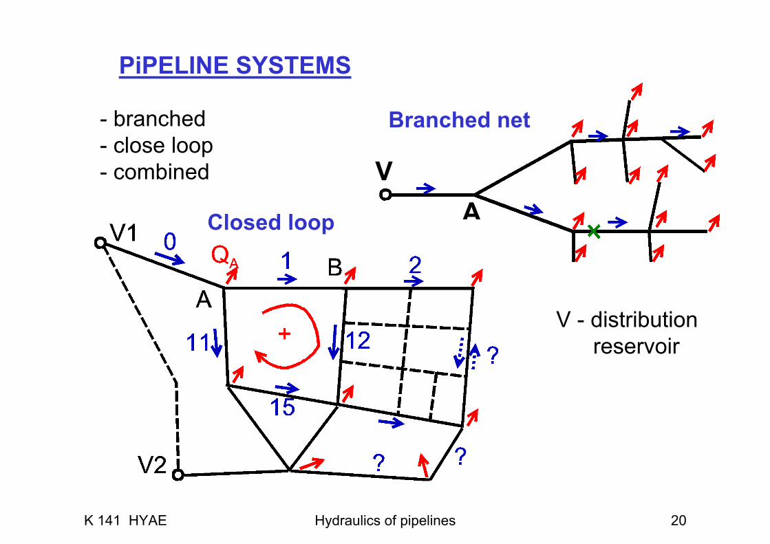
Branched net
Closed loop
PiPELINE SYSTEMS
- branched- close loop- combined
V - distribution reservoir
K 141 HYAE Hydraulics of pipelines 21
WATER HAMMER
quick manipulation with closure, pump starting or failure⇓
rapid change of pressure (water hammer),in particular at long pipelines
protection against water hammer:• sufficiently slow manipulation with closures• air chambers, surge chambers (equilibrating towers)• ...

![Highly Branched Poly(α-Methylene-γ-Butyrolactone) from …file.scirp.org/pdf/OJPChem_2017112914172525.pdf · 2017-12-01 · ... (3.00 g, 0.013 mol), and L-valinol [(S)-(+)-2-Amino-3-methyl-1-butanol]](https://static.fdocument.org/doc/165x107/5b1be3007f8b9a28258f0d54/highly-branched-poly-methylene-butyrolactone-from-filescirporgpdfojpchem.jpg)


![arXiv:1805.01934v1 [cs.CV] 4 May 2018arXiv:1805.01934v1 [cs.CV] 4 May 2018 burst alignment algorithms may fail in extreme low-light conditions and burst pipelines are not designed](https://static.fdocument.org/doc/165x107/5ece9b44ad639c66df58292b/arxiv180501934v1-cscv-4-may-2018-arxiv180501934v1-cscv-4-may-2018-burst.jpg)