HOLLOWCORE WORKED EXAMPLE - Concrete Society
20
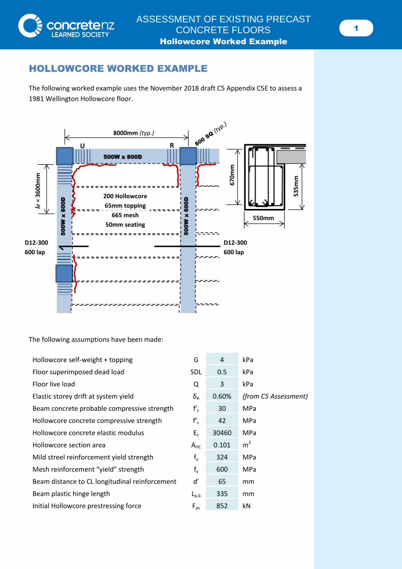
1 ASSESSMENT OF EXISTING PRECAST CONCRETE FLOORS Hollowcore Worked Example HOLLOWCORE WORKED EXAMPLE The following worked example uses the November 2018 draft C5 Appendix C5E to assess a 1981 Wellington Hollowcore floor. The following assumptions have been made: Hollowcore self-weight + topping G 4 kPa Floor superimposed dead load SDL 0.5 kPa Floor live load Q 3 kPa Elastic storey drift at system yield δ e 0.60% (from C5 Assessment) Beam concrete probable compressive strength f' c 30 MPa Hollowcore concrete compressive strength f’ c 42 MPa Hollowcore concrete elastic modulus E c 30460 MPa Hollowcore section area A HC 0.101 m 2 Mild streel reinforcement yield strength f y 324 MPa Mesh reinforcement “yield” strength f y 600 MPa Beam distance to CL longitudinal reinforcement d’ 65 mm Beam plastic hinge length L p,b 335 mm Initial Hollowcore prestressing force F ps 852 kN le = 3600mm D12-300 600 lap D12-300 600 lap 500W x 600D 500W x 800D 500W x 800D 8000mm (typ.) U R 200 Hollowcore 65mm topping 665 mesh 50mm seating 670mm 550mm 535mm
Transcript of HOLLOWCORE WORKED EXAMPLE - Concrete Society
1 ASSESSMENT OF EXISTING PRECAST
CONCRETE FLOORS Hollowcore Worked Example
HOLLOWCORE WORKED EXAMPLE
The following worked example uses the November 2018 draft C5 Appendix C5E to assess a
1981 Wellington Hollowcore floor.
The following assumptions have been made:
Hollowcore self-weight + topping G 4 kPa
Floor superimposed dead load SDL 0.5 kPa
Floor live load Q 3 kPa
Elastic storey drift at system yield δe 0.60% (from C5 Assessment)
Beam concrete probable compressive strength f'c 30 MPa
Hollowcore concrete compressive strength f’c 42 MPa
Hollowcore concrete elastic modulus Ec 30460 MPa
Hollowcore section area AHC 0.101 m2
Mild streel reinforcement yield strength fy 324 MPa
Mesh reinforcement “yield” strength fy 600 MPa
Beam distance to CL longitudinal reinforcement d’ 65 mm
Beam plastic hinge length Lp,b 335 mm
Initial Hollowcore prestressing force Fps 852 kN
le =
36
00
mm
D12-300
600 lap
D12-300
600 lap
500
W x
600
D
500W x 800D
500
W x
800
D
8000mm (typ.)
U
R
200 Hollowcore
65mm topping
665 mesh
50mm seating
6
70
mm
550mm
53
5m
m
2 ASSESSMENT OF EXISTING PRECAST
CONCRETE FLOORS Hollowcore Worked Example
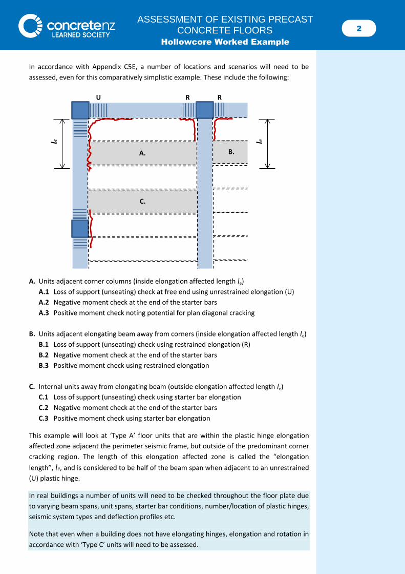
In accordance with Appendix C5E, a number of locations and scenarios will need to be
assessed, even for this comparatively simplistic example. These include the following:
A. Units adjacent corner columns (inside elongation affected length le)
A.1 Loss of support (unseating) check at free end using unrestrained elongation (U)
A.2 Negative moment check at the end of the starter bars
A.3 Positive moment check noting potential for plan diagonal cracking
B. Units adjacent elongating beam away from corners (inside elongation affected length le)
B.1 Loss of support (unseating) check using restrained elongation (R)
B.2 Negative moment check at the end of the starter bars
B.3 Positive moment check using restrained elongation
C. Internal units away from elongating beam (outside elongation affected length le)
C.1 Loss of support (unseating) check using starter bar elongation
C.2 Negative moment check at the end of the starter bars
C.3 Positive moment check using starter bar elongation
This example will look at ‘Type A’ floor units that are within the plastic hinge elongation
affected zone adjacent the perimeter seismic frame, but outside of the predominant corner
cracking region. The length of this elongation affected zone is called the “elongation
length”, le, and is considered to be half of the beam span when adjacent to an unrestrained
(U) plastic hinge.
In real buildings a number of units will need to be checked throughout the floor plate due
to varying beam spans, unit spans, starter bar conditions, number/location of plastic hinges,
seismic system types and deflection profiles etc.
Note that even when a building does not have elongating hinges, elongation and rotation in
accordance with ‘Type C’ units will need to be assessed.
A.
C.
B.
le
U R R
le
3 ASSESSMENT OF EXISTING PRECAST
CONCRETE FLOORS Hollowcore Worked Example
A. UNITS ADJACENT CORNER COLUMNS
A.1 Loss of support (C5E.5.2)
Loss of support need not be checked if the hollows at the supports are reinforced in
accordance with the detail provided within NZS 3101:2006 A3. Because this is a 1980s
building its detailing does not satisfy this provision.
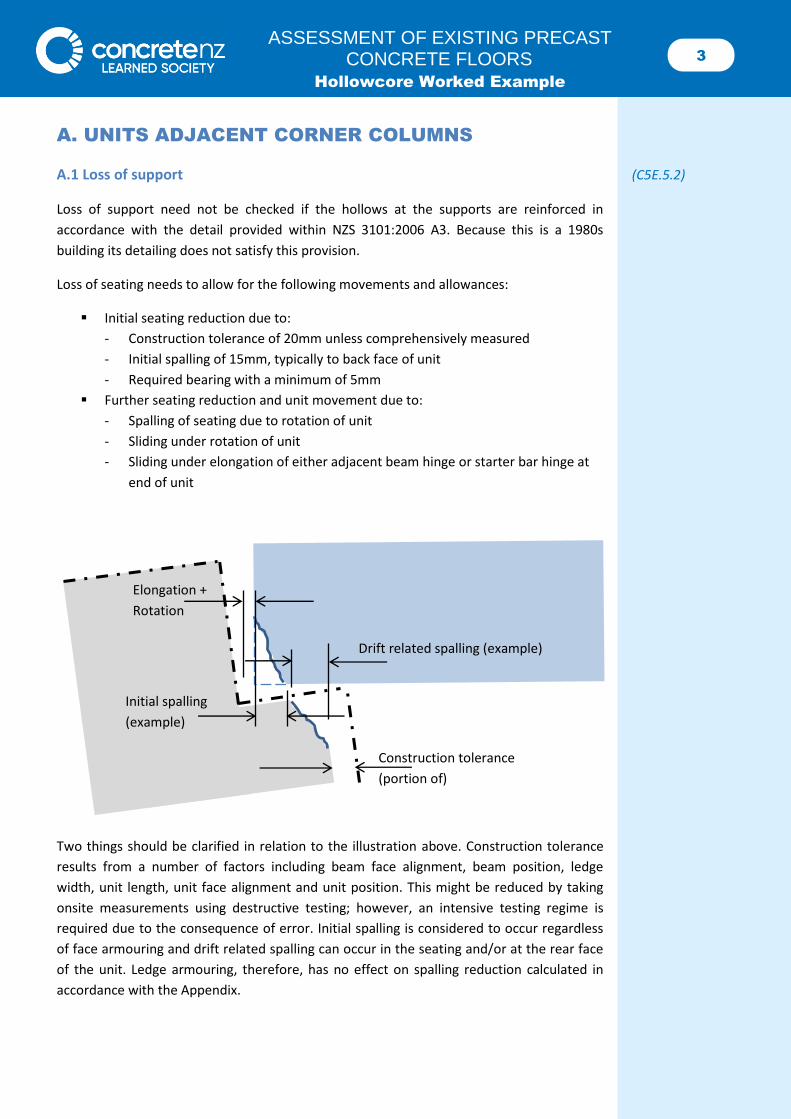
Loss of seating needs to allow for the following movements and allowances:
Initial seating reduction due to:
- Construction tolerance of 20mm unless comprehensively measured
- Initial spalling of 15mm, typically to back face of unit
- Required bearing with a minimum of 5mm
Further seating reduction and unit movement due to:
- Spalling of seating due to rotation of unit
- Sliding under rotation of unit
- Sliding under elongation of either adjacent beam hinge or starter bar hinge at
end of unit
Two things should be clarified in relation to the illustration above. Construction tolerance
results from a number of factors including beam face alignment, beam position, ledge
width, unit length, unit face alignment and unit position. This might be reduced by taking
onsite measurements using destructive testing; however, an intensive testing regime is
required due to the consequence of error. Initial spalling is considered to occur regardless
of face armouring and drift related spalling can occur in the seating and/or at the rear face
of the unit. Ledge armouring, therefore, has no effect on spalling reduction calculated in
accordance with the Appendix.
Construction tolerance
(portion of)
Initial spalling
(example)
Drift related spalling (example)
Elongation +
Rotation
4 ASSESSMENT OF EXISTING PRECAST
CONCRETE FLOORS Hollowcore Worked Example
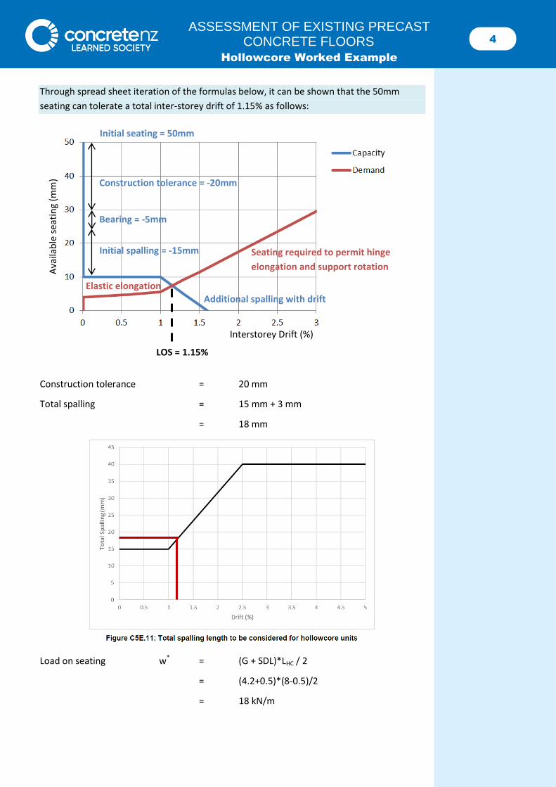
Through spread sheet iteration of the formulas below, it can be shown that the 50mm
seating can tolerate a total inter-storey drift of 1.15% as follows:
Construction tolerance = 20 mm
Total spalling = 15 mm + 3 mm
= 18 mm
Load on seating w* = (G + SDL)*LHC / 2
= (4.2+0.5)*(8-0.5)/2
= 18 kN/m
Ava
ilab
le s
eati
ng
(mm
)
Interstorey Drift (%)
Initial seating = 50mm
Construction tolerance = -20mm
Initial spalling = -15mm
Additional spalling with drift
Seating required to permit hinge
elongation and support rotation
LOS = 1.15%
Elastic elongation
Bearing = -5mm
5 ASSESSMENT OF EXISTING PRECAST
CONCRETE FLOORS Hollowcore Worked Example
Bearing length required Lbear = w*/(0.85 f’c) (NZS3101 cl16.3)
= 18*(1200/885)/(0.85*30)
= 1 mm < 5 mm
= 5 mm
Remaining seating capacity = 50 – 20 – 18 – 5
= 7 mm
Frame elongation
𝛿𝑒𝑙 = 2.6𝜃𝑝
2(𝑑 − 𝑑′) ≤ 0.036ℎ𝑏 (Eqn C5E.1)
Plastic beam rotation θp = θpcol
* L / (L - hcol - Lp)
= (1.15-0.6)*8000/(8000-800-335)
= 0.6%
Beam elongation δel = 2.6*0.006/2*(800-65*2)
= 5 mm > 0.5hb
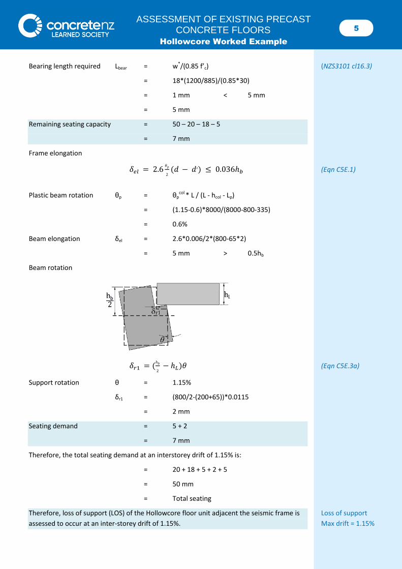
Beam rotation
𝛿𝑟1 = (ℎ𝑏
2 − ℎ𝐿)𝜃 (Eqn C5E.3a)
Support rotation θ = 1.15%
δr1 = (800/2-(200+65))*0.0115
= 2 mm
Seating demand = 5 + 2
= 7 mm
Therefore, the total seating demand at an interstorey drift of 1.15% is:
= 20 + 18 + 5 + 2 + 5
= 50 mm
= Total seating
Therefore, loss of support (LOS) of the Hollowcore floor unit adjacent the seismic frame is Loss of support
assessed to occur at an inter-storey drift of 1.15%. Max drift = 1.15%
6 ASSESSMENT OF EXISTING PRECAST
CONCRETE FLOORS Hollowcore Worked Example
Note that a check that rotation and elongation of the unit itself without frame elongation
should be completed to ensure this is not a critical mechanism. This check is critical for
“Type C” units, which are assessed to not experience the effects of beam elongation.
Check at the previous limiting drift of 1.15% to prove that the mechanism is not critical:
Unit elongation
𝛿𝑒𝑙_𝑢𝑛𝑖𝑡 = 1.3𝜃𝑝
2(ℎ𝐿 − 𝑑′) ≤ 0.018ℎ𝐿 (Eqn C5E.4)
Unit rotation θp = (δ – δe)* L / (L – 2s)
= (1.15-0.6)*7500/(7500-2*300)
= 0.6%
Unit elongation δel_unit = 1.3*0.006/2*(265-30)
= 1 mm
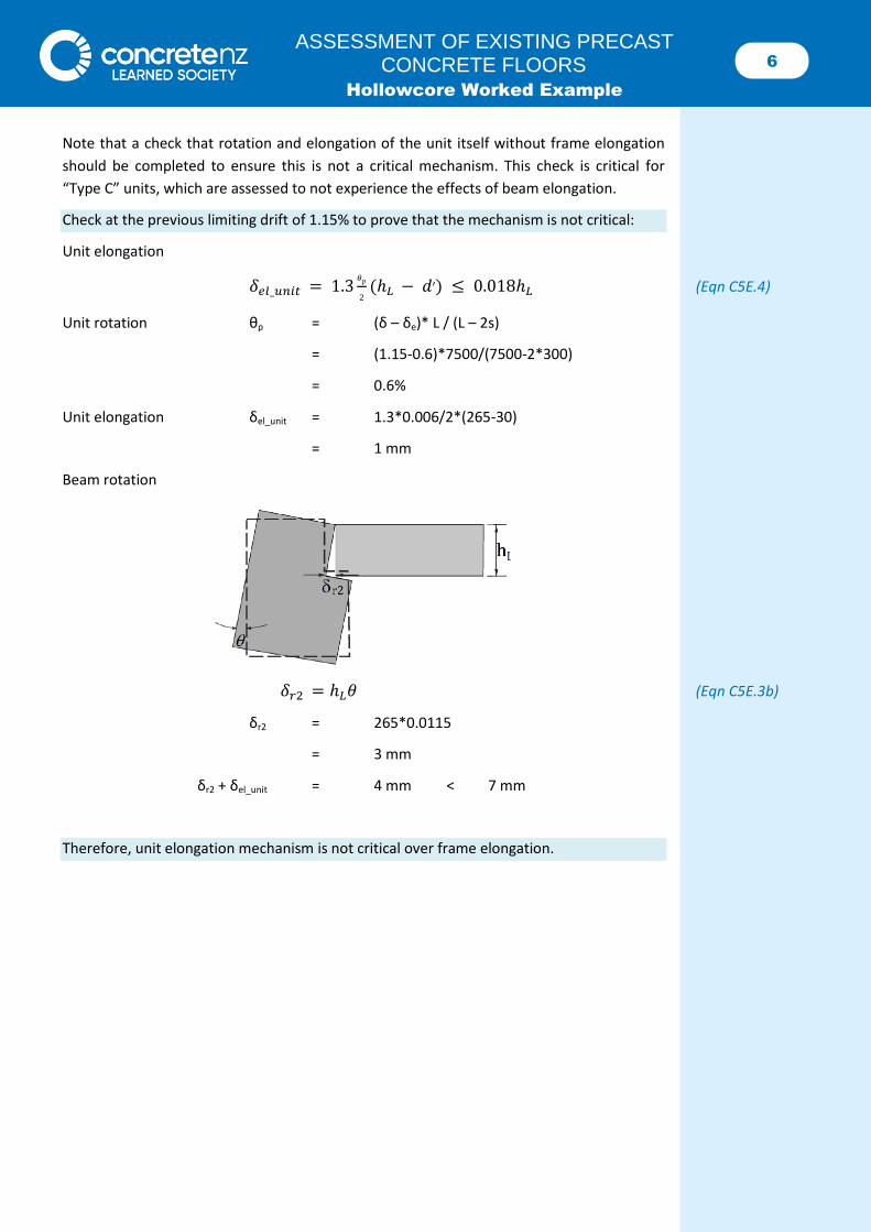
Beam rotation
𝛿𝑟2 = ℎ𝐿𝜃 (Eqn C5E.3b)
δr2 = 265*0.0115
= 3 mm
δr2 + δel_unit = 4 mm < 7 mm
Therefore, unit elongation mechanism is not critical over frame elongation.
7 ASSESSMENT OF EXISTING PRECAST
CONCRETE FLOORS Hollowcore Worked Example
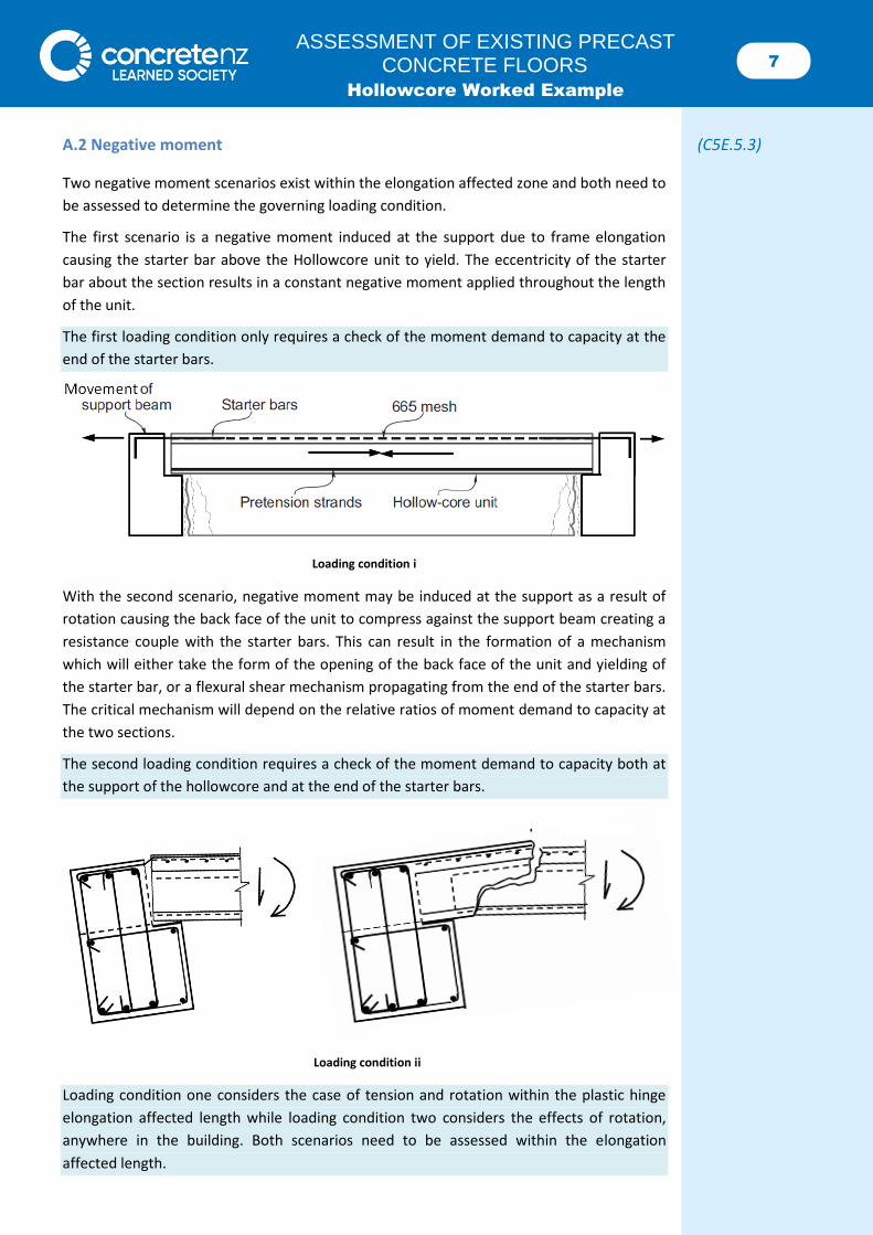
A.2 Negative moment (C5E.5.3)
Two negative moment scenarios exist within the elongation affected zone and both need to
be assessed to determine the governing loading condition.
The first scenario is a negative moment induced at the support due to frame elongation
causing the starter bar above the Hollowcore unit to yield. The eccentricity of the starter
bar about the section results in a constant negative moment applied throughout the length
of the unit.
The first loading condition only requires a check of the moment demand to capacity at the
end of the starter bars.
Loading condition i
With the second scenario, negative moment may be induced at the support as a result of
rotation causing the back face of the unit to compress against the support beam creating a
resistance couple with the starter bars. This can result in the formation of a mechanism
which will either take the form of the opening of the back face of the unit and yielding of
the starter bar, or a flexural shear mechanism propagating from the end of the starter bars.
The critical mechanism will depend on the relative ratios of moment demand to capacity at
the two sections.
The second loading condition requires a check of the moment demand to capacity both at
the support of the hollowcore and at the end of the starter bars.
Loading condition ii
Loading condition one considers the case of tension and rotation within the plastic hinge
elongation affected length while loading condition two considers the effects of rotation,
anywhere in the building. Both scenarios need to be assessed within the elongation
affected length.
8 ASSESSMENT OF EXISTING PRECAST
CONCRETE FLOORS Hollowcore Worked Example
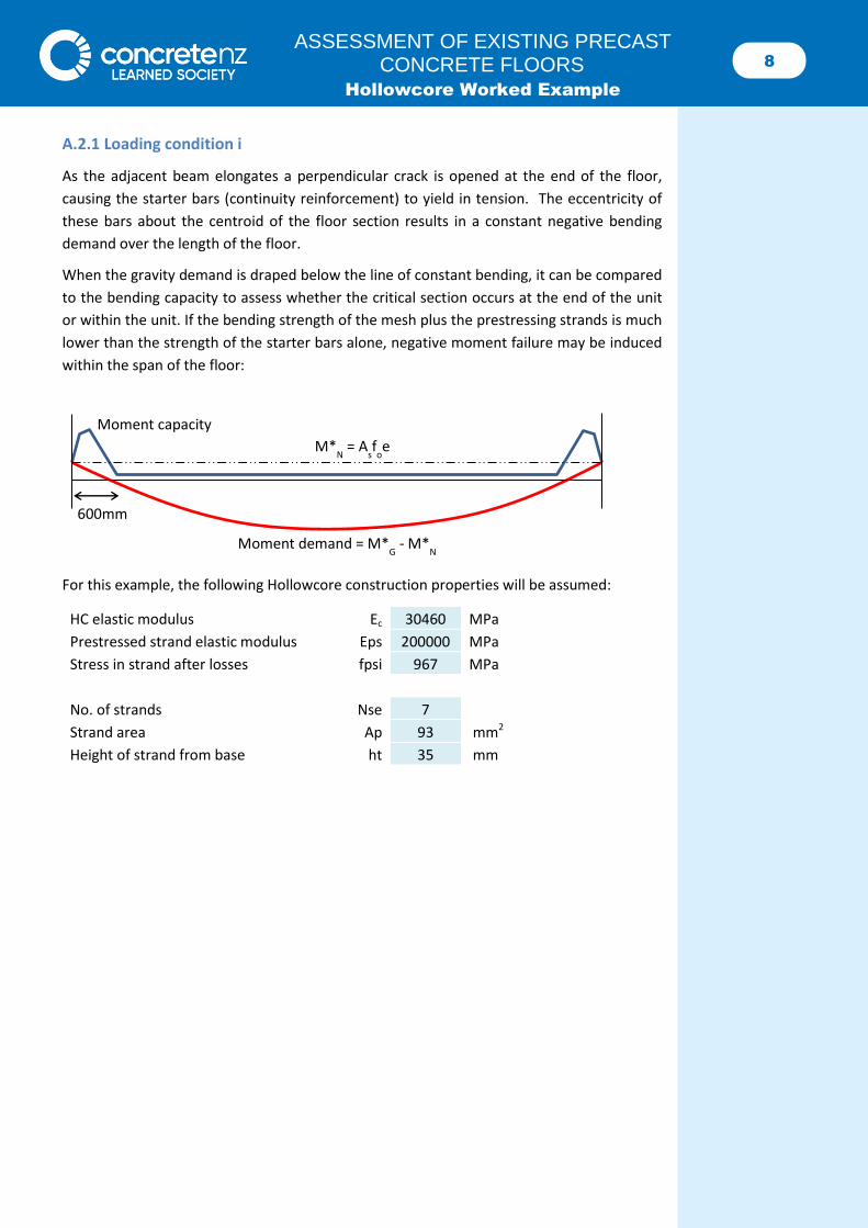
A.2.1 Loading condition i
As the adjacent beam elongates a perpendicular crack is opened at the end of the floor,
causing the starter bars (continuity reinforcement) to yield in tension. The eccentricity of
these bars about the centroid of the floor section results in a constant negative bending
demand over the length of the floor.
When the gravity demand is draped below the line of constant bending, it can be compared
to the bending capacity to assess whether the critical section occurs at the end of the unit
or within the unit. If the bending strength of the mesh plus the prestressing strands is much
lower than the strength of the starter bars alone, negative moment failure may be induced
within the span of the floor:
For this example, the following Hollowcore construction properties will be assumed:
HC elastic modulus Ec 30460 MPa
Prestressed strand elastic modulus Eps 200000 MPa
Stress in strand after losses fpsi 967 MPa
No. of strands Nse 7
Strand area Ap 93 mm2
Height of strand from base ht 35 mm
Moment capacity
Moment demand = M*G - M*
N
M*N = A
sf
oe
600mm
9 ASSESSMENT OF EXISTING PRECAST
CONCRETE FLOORS Hollowcore Worked Example
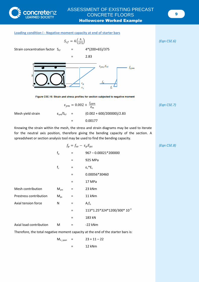
Loading condition i - Negative moment capacity at end of starter bars
𝑆𝑐𝑓 = 4 (ℎ
375) (Eqn C5E.6)
Strain concentration factor Scf = 4*(200+65)/375
= 2.83
ε𝑦𝑚 = 0.002 + 𝑓𝑦𝑝𝑚
𝐸𝑚 (Eqn C5E.7)
Mesh yield strain εym/Scf = (0.002 + 600/200000)/2.83
= 0.00177
Knowing the strain within the mesh, the stress and strain diagrams may be used to iterate
for the neutral axis position, therefore giving the bending capacity of the section. A
spreadsheet or section analysis tool may be used to find the bending capacity.
𝑓𝑝 = 𝑓𝑠𝑒 − ε𝑝𝐸𝑝𝑠 (Eqn C5E.8)
fp = 967 – 0.00021*200000
= 925 MPa
fc = εc*Ec
= 0.00056*30460
= 17 MPa
Mesh contribution Mym = 23 kNm
Prestress contribution Mps = 11 kNm
Axial tension force N = Asfo
= 113*1.25*324*1200/300* 10-3
= 183 kN
Axial load contribution M = -22 kNm
Therefore, the total negative moment capacity at the end of the starter bars is:
Mn_span = 23 + 11 – 22
= 12 kNm
10 ASSESSMENT OF EXISTING PRECAST
CONCRETE FLOORS Hollowcore Worked Example
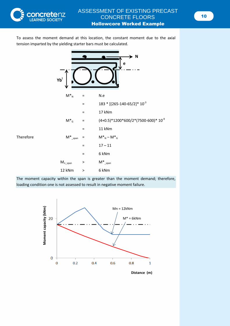
To assess the moment demand at this location, the constant moment due to the axial
tension imparted by the yielding starter bars must be calculated.
M*N = N.e
= 183 * [(265-140-65/2]* 10-3
= 17 kNm
M*G = (4+0.5)*1200*600/2*(7500-600)* 10-9
= 11 kNm
Therefore M*_span = M*N – M*G
= 17 – 11
= 6 kNm
Mn_span > M*_span
12 kNm > 6 kNm
The moment capacity within the span is greater than the moment demand; therefore,
loading condition one is not assessed to result in negative moment failure.
Ybl
e
N
Mo
me
nt
cap
acit
y (k
Nm
)
Distance (m)
Mn = 12kNm
M* = 6kNm
11 ASSESSMENT OF EXISTING PRECAST
CONCRETE FLOORS Hollowcore Worked Example
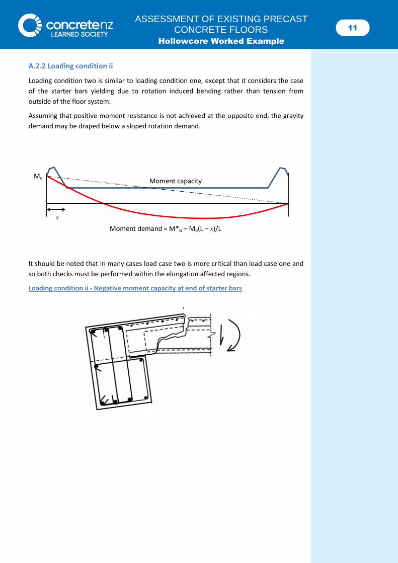
A.2.2 Loading condition ii
Loading condition two is similar to loading condition one, except that it considers the case
of the starter bars yielding due to rotation induced bending rather than tension from
outside of the floor system.
Assuming that positive moment resistance is not achieved at the opposite end, the gravity
demand may be draped below a sloped rotation demand.
It should be noted that in many cases load case two is more critical than load case one and
so both checks must be performed within the elongation affected regions.
Loading condition ii - Negative moment capacity at end of starter bars
Moment capacity
Moment demand = M*G – Mo(L – x)/L
Mo
x
12 ASSESSMENT OF EXISTING PRECAST
CONCRETE FLOORS Hollowcore Worked Example
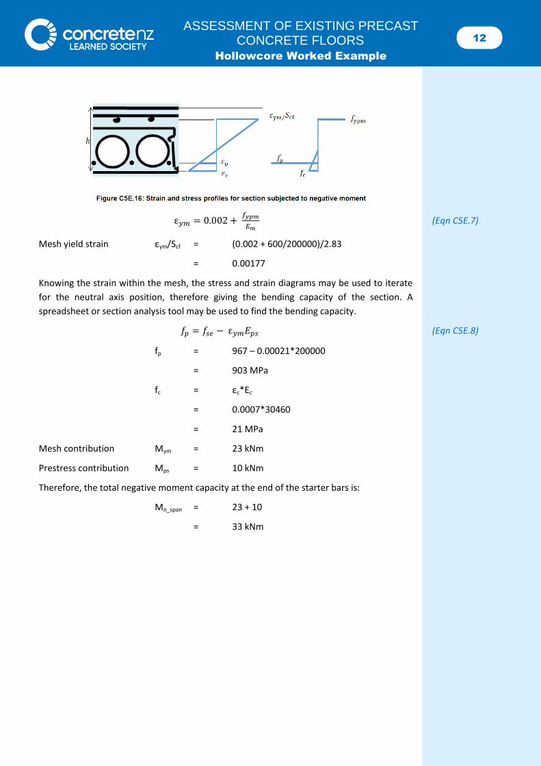
ε𝑦𝑚 = 0.002 + 𝑓𝑦𝑝𝑚
𝐸𝑚 (Eqn C5E.7)
Mesh yield strain εym/Scf = (0.002 + 600/200000)/2.83
= 0.00177
Knowing the strain within the mesh, the stress and strain diagrams may be used to iterate
for the neutral axis position, therefore giving the bending capacity of the section. A
spreadsheet or section analysis tool may be used to find the bending capacity.
𝑓𝑝 = 𝑓𝑠𝑒 − ε𝑦𝑚𝐸𝑝𝑠 (Eqn C5E.8)
fp = 967 – 0.00021*200000
= 903 MPa
fc = εc*Ec
= 0.0007*30460
= 21 MPa
Mesh contribution Mym = 23 kNm
Prestress contribution Mps = 10 kNm
Therefore, the total negative moment capacity at the end of the starter bars is:
Mn_span = 23 + 10
= 33 kNm
13 ASSESSMENT OF EXISTING PRECAST
CONCRETE FLOORS Hollowcore Worked Example
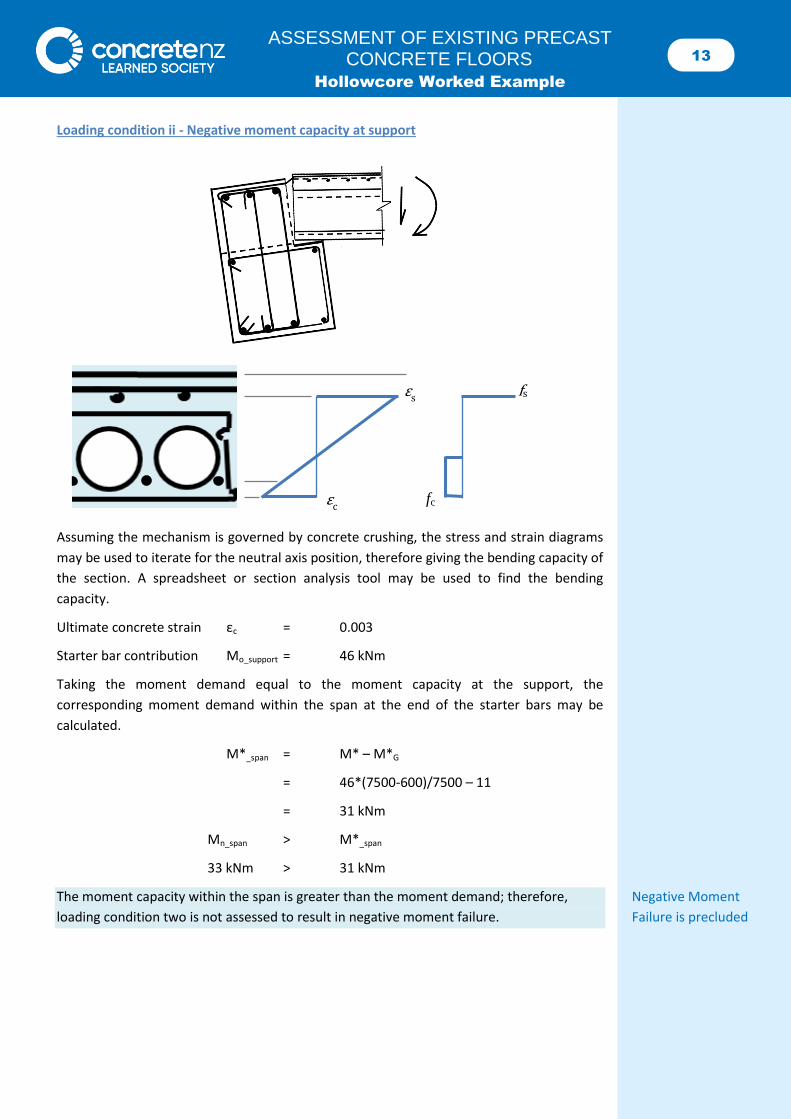
Loading condition ii - Negative moment capacity at support
Assuming the mechanism is governed by concrete crushing, the stress and strain diagrams
may be used to iterate for the neutral axis position, therefore giving the bending capacity of
the section. A spreadsheet or section analysis tool may be used to find the bending
capacity.
Ultimate concrete strain εc = 0.003
Starter bar contribution Mo_support = 46 kNm
Taking the moment demand equal to the moment capacity at the support, the
corresponding moment demand within the span at the end of the starter bars may be
calculated.
M*_span = M* – M*G
= 46*(7500-600)/7500 – 11
= 31 kNm
Mn_span > M*_span
33 kNm > 31 kNm
The moment capacity within the span is greater than the moment demand; therefore, Negative Moment
loading condition two is not assessed to result in negative moment failure. Failure is precluded
εc
εs fs
fc
14 ASSESSMENT OF EXISTING PRECAST
CONCRETE FLOORS Hollowcore Worked Example
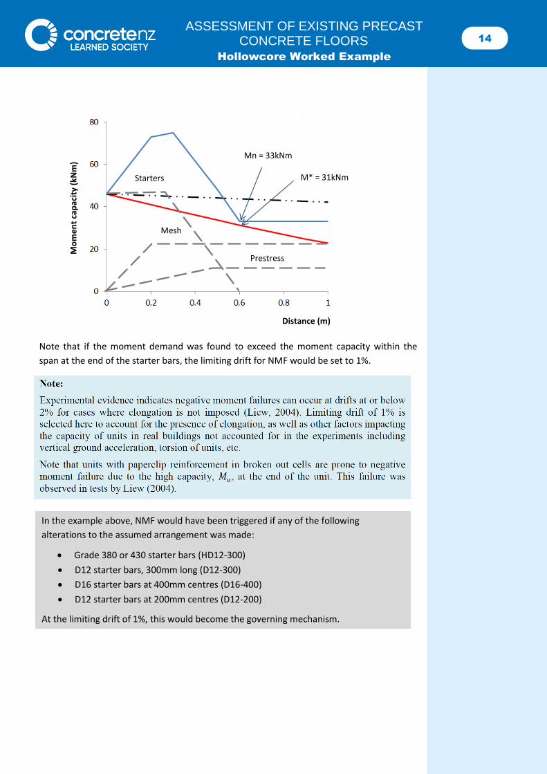
Note that if the moment demand was found to exceed the moment capacity within the
span at the end of the starter bars, the limiting drift for NMF would be set to 1%.
In the example above, NMF would have been triggered if any of the following
alterations to the assumed arrangement was made:
Grade 380 or 430 starter bars (HD12-300)
D12 starter bars, 300mm long (D12-300)
D16 starter bars at 400mm centres (D16-400)
D12 starter bars at 200mm centres (D12-200)
At the limiting drift of 1%, this would become the governing mechanism.
Prestress
Mo
me
nt
cap
acit
y (k
Nm
)
Distance (m)
Mesh
Starters
Mn = 33kNm
M* = 31kNm
15 ASSESSMENT OF EXISTING PRECAST
CONCRETE FLOORS Hollowcore Worked Example
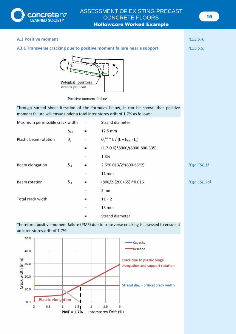
A.3 Positive moment (C5E.5.4)
A3.1 Transverse cracking due to positive moment failure near a support (C5E.5.5)
Through spread sheet iteration of the formulas below, it can be shown that positive
moment failure will ensue under a total inter-storey drift of 1.7% as follows:
Maximum permissible crack width = Strand diameter
Δtot = 12.5 mm
Plastic beam rotation θp = θpcol
* L / (L – hcol - Lp)
= (1.7-0.6)*8000/(8000-800-335)
= 1.3%
Beam elongation δel = 2.6*0.013/2*(800-65*2) (Eqn C5E.1)
= 11 mm
Beam rotation δr1 = (800/2-(200+65))*0.016 (Eqn C5E.3a)
= 2 mm
Total crack width = 11 + 2
= 13 mm
= Strand diameter
Therefore, positive moment failure (PMF) due to transverse cracking is assessed to ensue at
an inter-storey drift of 1.7%.
Cra
ck w
idth
(m
m)
Interstorey Drift (%)
Strand dia. = critical crack width
Crack due to plastic hinge
elongation and support rotation
PMF = 1.7%
Elastic elongation
16 ASSESSMENT OF EXISTING PRECAST
CONCRETE FLOORS Hollowcore Worked Example
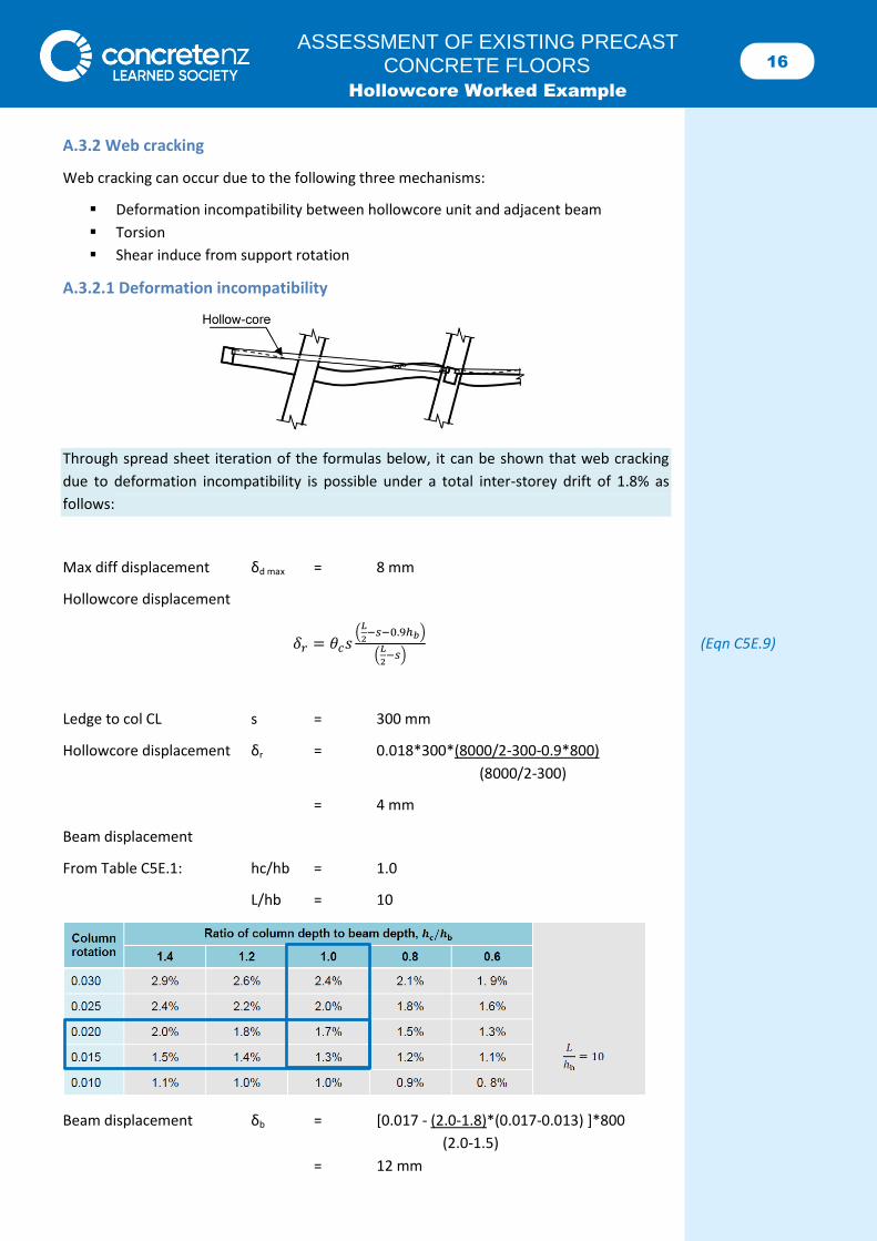
A.3.2 Web cracking
Web cracking can occur due to the following three mechanisms:
Deformation incompatibility between hollowcore unit and adjacent beam
Torsion
Shear induce from support rotation
A.3.2.1 Deformation incompatibility
Through spread sheet iteration of the formulas below, it can be shown that web cracking
due to deformation incompatibility is possible under a total inter-storey drift of 1.8% as
follows:
Max diff displacement δd max = 8 mm
Hollowcore displacement
𝛿𝑟 = 𝜃𝑐𝑠(
𝐿
2−𝑠−0.9ℎ𝑏)
(𝐿
2−𝑠)
(Eqn C5E.9)
Ledge to col CL s = 300 mm
Hollowcore displacement δr = 0.018*300*(8000/2-300-0.9*800)
(8000/2-300)
= 4 mm
Beam displacement
From Table C5E.1: hc/hb = 1.0
L/hb = 10
Beam displacement δb = [0.017 - (2.0-1.8)*(0.017-0.013) ]*800
(2.0-1.5)
= 12 mm
17 ASSESSMENT OF EXISTING PRECAST
CONCRETE FLOORS Hollowcore Worked Example
Differential displacement δd = δb - δr
= 12 – 4
= 8 mm = δd max
Therefore, web cracking is assessed to ensue at an inter-storey drift of 1.8%. This is greater
than transverse cracking at 1.7%, and so transverse cracking is the critical PMF mechanism.
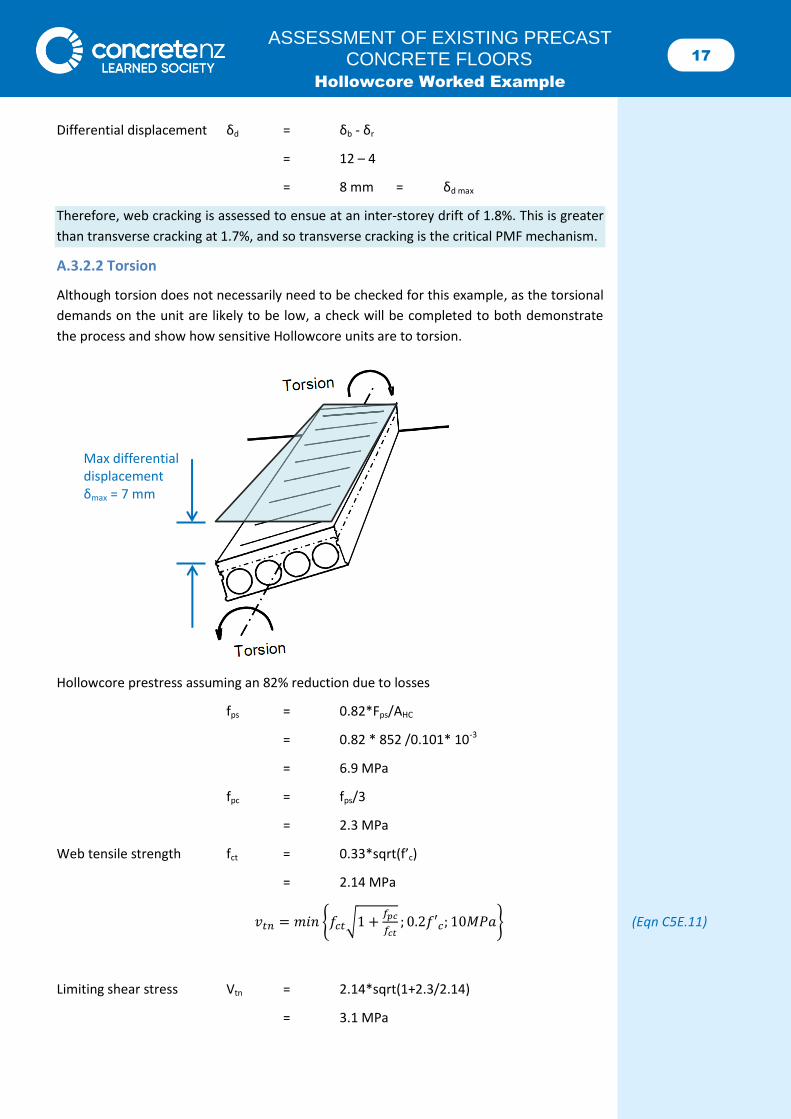
A.3.2.2 Torsion
Although torsion does not necessarily need to be checked for this example, as the torsional
demands on the unit are likely to be low, a check will be completed to both demonstrate
the process and show how sensitive Hollowcore units are to torsion.
Hollowcore prestress assuming an 82% reduction due to losses
fps = 0.82*Fps/AHC
= 0.82 * 852 /0.101* 10-3
= 6.9 MPa
fpc = fps/3
= 2.3 MPa
Web tensile strength fct = 0.33*sqrt(f’c)
= 2.14 MPa
𝑣𝑡𝑛 = 𝑚𝑖𝑛 {𝑓𝑐𝑡√1 +𝑓𝑝𝑐
𝑓𝑐𝑡; 0.2𝑓′𝑐; 10𝑀𝑃𝑎} (Eqn C5E.11)
Limiting shear stress Vtn = 2.14*sqrt(1+2.3/2.14)
= 3.1 MPa
Max differential displacement δmax = 7 mm
18 ASSESSMENT OF EXISTING PRECAST
CONCRETE FLOORS Hollowcore Worked Example
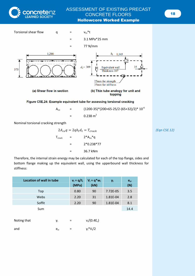
Torsional shear flow q = vtn*t
= 3.1 MPa*25 mm
= 77 N/mm
Aco = (1200-35)*(200+65-25/2-(65+32)/2)* 10-6
= 0.238 m2
Nominal torsional cracking strength
2𝐴𝑐𝑜𝑞 = 2𝑞𝑏𝑡𝑑𝑡 = 𝑇𝑐𝑟𝑎𝑐𝑘 (Eqn C5E.12)
Tcrack = 2*Aco*q
= 2*0.238*77
= 36.7 kNm
Therefore, the internal strain energy may be calculated for each of the top flange, sides and
bottom flange making up the equivalent wall, using the upperbound wall thickness for
stiffness:
Noting that γi = vi/(0.4Ec)
and eεi = γi*Vi/2
Location of wall in tube vi = q/ti Vi = q*wi γi eεi
(MPa) (kN) (N)
Top 0.80 90 7.72E-05 3.5
Webs 2.20 31 1.81E-04 2.8
Soffit 2.20 90 1.81E-04 8.1
Sum 14.4
19 ASSESSMENT OF EXISTING PRECAST
CONCRETE FLOORS Hollowcore Worked Example
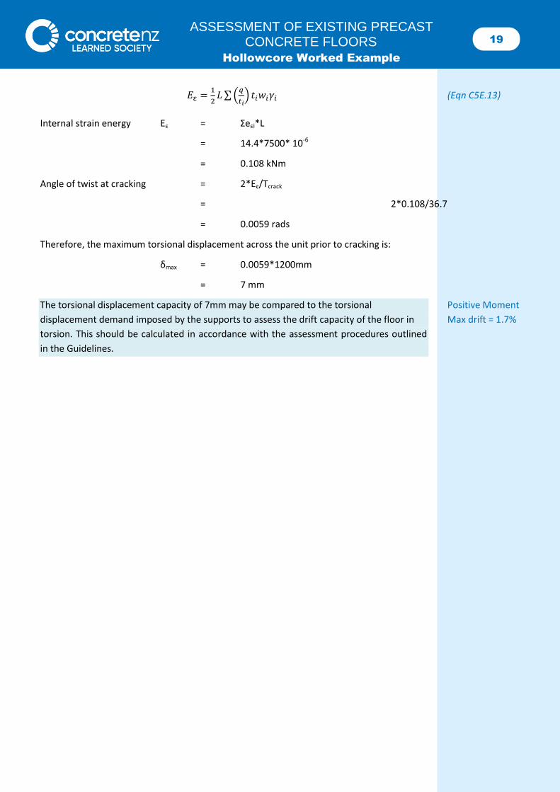
𝐸ε =1
2𝐿 ∑ (
𝑞
𝑡𝑖) 𝑡𝑖𝑤𝑖𝛾𝑖 (Eqn C5E.13)
Internal strain energy Eε = Σeεi*L
= 14.4*7500* 10-6
= 0.108 kNm
Angle of twist at cracking = 2*Eε/Tcrack
= 2*0.108/36.7
= 0.0059 rads
Therefore, the maximum torsional displacement across the unit prior to cracking is:
δmax = 0.0059*1200mm
= 7 mm
The torsional displacement capacity of 7mm may be compared to the torsional Positive Moment
displacement demand imposed by the supports to assess the drift capacity of the floor in Max drift = 1.7%
torsion. This should be calculated in accordance with the assessment procedures outlined
in the Guidelines.
20 ASSESSMENT OF EXISTING PRECAST
CONCRETE FLOORS Hollowcore Worked Example
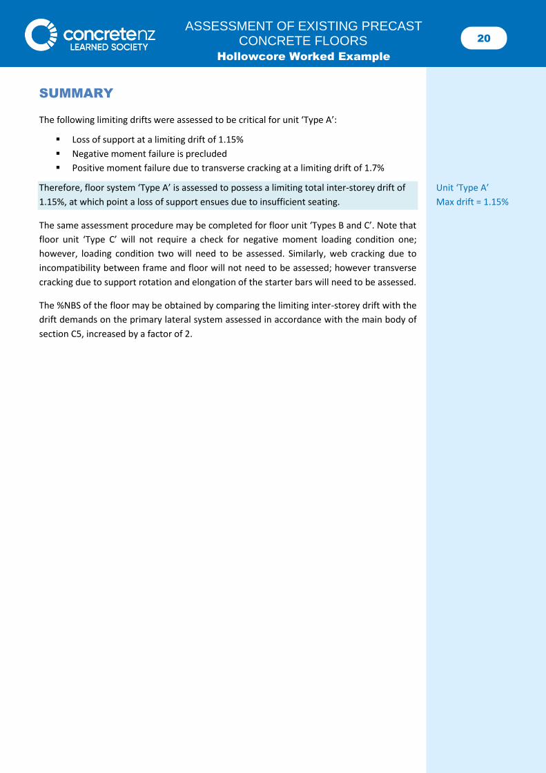
SUMMARY
The following limiting drifts were assessed to be critical for unit ‘Type A’:
Loss of support at a limiting drift of 1.15%
Negative moment failure is precluded
Positive moment failure due to transverse cracking at a limiting drift of 1.7%
Therefore, floor system ‘Type A’ is assessed to possess a limiting total inter-storey drift of Unit ‘Type A’
1.15%, at which point a loss of support ensues due to insufficient seating. Max drift = 1.15%
The same assessment procedure may be completed for floor unit ‘Types B and C’. Note that
floor unit ‘Type C’ will not require a check for negative moment loading condition one;
however, loading condition two will need to be assessed. Similarly, web cracking due to
incompatibility between frame and floor will not need to be assessed; however transverse
cracking due to support rotation and elongation of the starter bars will need to be assessed.
The %NBS of the floor may be obtained by comparing the limiting inter-storey drift with the
drift demands on the primary lateral system assessed in accordance with the main body of
section C5, increased by a factor of 2.