HMPC for Upper Stage Attitude Control
21
Hybrid MPC for Attitude Control of Spacecraft with Impulsive Thrusters P. Sopasakis a , D. Bernardini a,c , H. Strauch b , S. Bennani d and A. Bemporad a,c a Institute for Advanced Studies Lucca, b Airbus DS, c ODYS Srl d European Space Agency July 14, 2015
-
Upload
pantelis-sopasakis -
Category
Technology
-
view
16 -
download
0
Transcript of HMPC for Upper Stage Attitude Control
Hybrid MPC for Attitude Control of Spacecraft withImpulsive Thrusters
P. Sopasakisa, D. Bernardinia,c, H. Strauchb,S. Bennanid and A. Bemporada,c
a Institute for Advanced Studies Lucca,b Airbus DS, c ODYS Srld European Space Agency
July 14, 2015
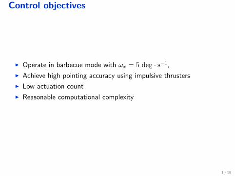
Control objectives
I Operate in barbecue mode with ωx = 5 deg · s−1,
I Achieve high pointing accuracy using impulsive thrusters
I Low actuation count
I Reasonable computational complexity
1 / 15
I. Attitude Modelling
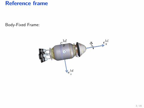
Reference frame
Body-Fixed Frame:
2 / 15
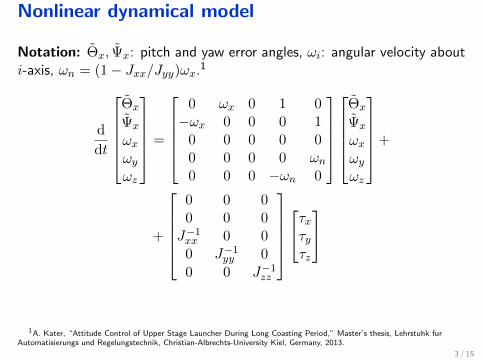
Nonlinear dynamical model
Notation: Θ̃x, Ψ̃x: pitch and yaw error angles, ωi: angular velocity abouti-axis, ωn = (1− Jxx/Jyy)ωx.1
d
dt
Θ̃x
Ψ̃x
ωxωyωz
=
0 ωx 0 1 0−ωx 0 0 0 1
0 0 0 0 00 0 0 0 ωn0 0 0 −ωn 0
Θ̃x
Ψ̃x
ωxωyωz
+
+
0 0 00 0 0J−1xx 0 0
0 J−1yy 0
0 0 J−1zz
τxτyτz
1A. Kater, “Attitude Control of Upper Stage Launcher During Long Coasting Period,” Master’s thesis, Lehrstuhk furAutomatisierungs und Regelungstechnik, Christian-Albrechts-University Kiel, Germany, 2013.
3 / 15
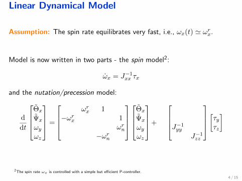
Linear Dynamical Model
Assumption: The spin rate equilibrates very fast, i.e., ωx(t) ' ωrx.
Model is now written in two parts - the spin model2:
ω̇x = J−1xx τx
and the nutation/precession model:
d
dt
Θ̃x
Ψ̃x
ωyωz
=
ωrx 1
−ωrx 1ωrn
−ωrn
Θ̃x
Ψ̃x
ωyωz
+
J−1yyJ−1zz
[τyτz]
2The spin rate ωx is controlled with a simple but efficient P-controller.
4 / 15
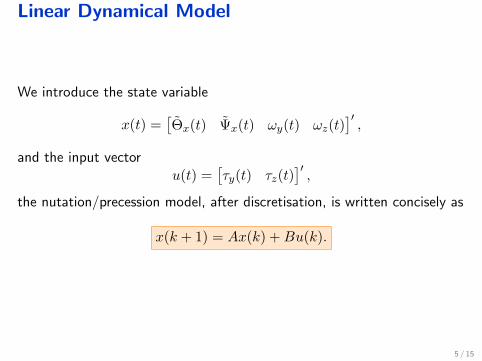
Linear Dynamical Model
We introduce the state variable
x(t) =[Θ̃x(t) Ψ̃x(t) ωy(t) ωz(t)
]′,
and the input vectoru(t) =
[τy(t) τz(t)
]′,
the nutation/precession model, after discretisation, is written concisely as
x(k + 1) = Ax(k) +Bu(k).
5 / 15
II. Impulsive Thrusters
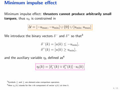
Minimum impulse effect
Minimum impulse effect: thrusters cannot produce arbitrarily smalltorques, thus uk is constrained in
U = [−umax,−umin] ∪ {0} ∪ [umin, umax]
We introduce the binary vectors δ− and δ+ so that3
δ−(k) = [u(k) ≤ −umin],
δ+(k) = [u(k) ≥ umin],
and the auxiliary variable ηk defined as4
ηi(k) = [δ−i (k) ∨ δ+i (k)] · ui(k)
3Symbols ≤ and ≥ are element-wise comparison operators.4Here ηi(k) stands for the i-th component of vector η(k) at time k.
6 / 15
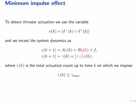
Minimum impulse effect
To detect thruster actuation we use the variable
v(k) = [δ−(k) ∨ δ+(k)]
and we recast the system dynamics as
z(k + 1) = Az(k) +Bη(k) + f,
γ(k + 1) = γ(k) + [ 1 1 ] v(k),
where γ(k) is the total actuation count up to time k on which we impose:
γ(k) ≤ γmax.
7 / 15
III. Hybrid MPC
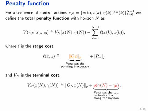
Penalty function
For a sequence of control actions πN = {u(k), v(k), η(k), δ±(k)}N−1k=0 wedefine the total penalty function with horizon N as
V (πN ;x0, γ0) , VN (x(N), γ(N)) +
N−1∑k=0
`(x(k), z(k)),
where ` is the stage cost
`(x, z) , ‖Qx‖p︸ ︷︷ ︸Penalises the
pointing inaccuracy
+‖Rz‖p
and VN is the terminal cost,
VN (x(N), γ(N)) , ‖QNx(N)‖p + ρ(γ(N)− γ0)︸ ︷︷ ︸Penalises the tot.actuation count
along the horizon
.
8 / 15
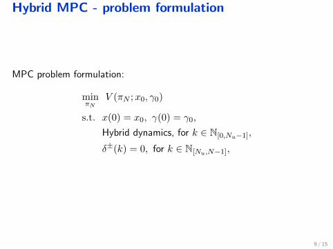
Hybrid MPC - problem formulation
MPC problem formulation:
minπN
V (πN ;x0, γ0)
s.t. x(0) = x0, γ(0) = γ0,
Hybrid dynamics, for k ∈ N[0,Nu−1],
δ±(k) = 0, for k ∈ N[Nu,N−1],
9 / 15
IV. Simulations
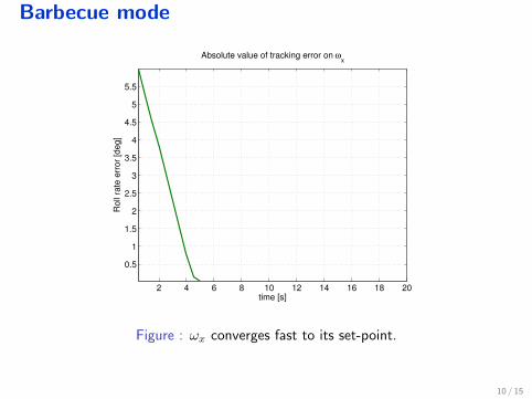
Barbecue mode
2 4 6 8 10 12 14 16 18 20
0.5
1
1.5
2
2.5
3
3.5
4
4.5
5
5.5
time [s]
Ro
ll ra
te e
rro
r [d
eg
]
Absolute value of tracking error on ωx
Figure : ωx converges fast to its set-point.
10 / 15
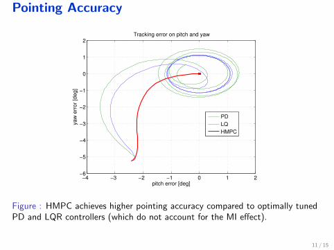
Pointing Accuracy
−4 −3 −2 −1 0 1 2−6
−5
−4
−3
−2
−1
0
1
2
pitch error [deg]
ya
w e
rro
r [d
eg
]
Tracking error on pitch and yaw
PD
LQ
HMPC
Figure : HMPC achieves higher pointing accuracy compared to optimally tunedPD and LQR controllers (which do not account for the MI effect).
11 / 15
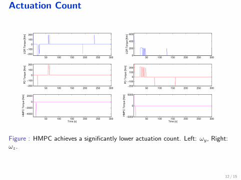
Actuation Count
50 100 150 200 250 300
−200
−100
0
100
200
LQ
R T
orq
ue
[N
m]
50 100 150 200 250 300−200
−100
0
100
200
PD
To
rqu
e [
Nm
]
50 100 150 200 250 300
−4000
−2000
0
2000
HM
PC
To
rqu
e [
Nm
]
Time [s]
50 100 150 200 250 3000
200
400
600
LQ
R T
orq
ue
[N
m]
50 100 150 200 250 300−200
−100
0
100
200
PD
To
rqu
e [
Nm
]
50 100 150 200 250 300−5000
0
5000
HM
PC
To
rqu
e [
Nm
]Time [s]
Figure : HMPC achieves a significantly lower actuation count. Left: ωy, Right:ωz.
12 / 15
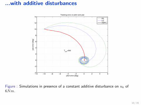
...with additive disturbances
−12 −10 −8 −6 −4 −2 0 2 4 6−4
−2
0
2
4
6
8
10
12
14
pitch error [deg]
yaw
err
or
[deg]
Tracking error on pitch and yaw
Tsim
=500
PD
LQ
HMPC
Figure : Simulations in presence of a constant additive disturbance on uk of6Nm.
13 / 15
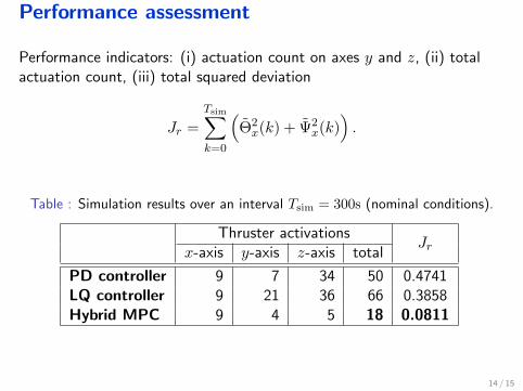
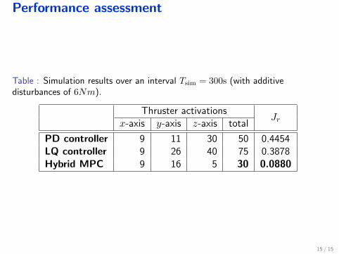
Performance assessment
Performance indicators: (i) actuation count on axes y and z, (ii) totalactuation count, (iii) total squared deviation
Jr =
Tsim∑k=0
(Θ̃2x(k) + Ψ̃2
x(k)).
Table : Simulation results over an interval Tsim = 300s (nominal conditions).
Thruster activationsJrx-axis y-axis z-axis total
PD controller 9 7 34 50 0.4741LQ controller 9 21 36 66 0.3858Hybrid MPC 9 4 5 18 0.0811
14 / 15
Performance assessment
Table : Simulation results over an interval Tsim = 300s (with additivedisturbances of 6Nm).
Thruster activationsJrx-axis y-axis z-axis total
PD controller 9 11 30 50 0.4454LQ controller 9 26 40 75 0.3878Hybrid MPC 9 16 5 30 0.0880
15 / 15
Thank you for your attention