HIOKI Portable Resistance Meter RM3548 - panel...
5
8 High-precision portable RESISTANCE METER measures from µΩ to MΩ RM3548 High-precision specs in a portable package(high accuracy of 0.02% rdg.) Design is ideal for maintenance and testing/measurement of large equipment. No warmup period or zero adjustment required. Dramatically improved overvoltage resistance (protection up to 70 V DC) High-precision specs in a portable package Expansive range options Measure from 0.0 µΩ to 3.5000 MΩ 0.1µΩ max. resolution, 0.02% basic accuracy Max. measurable current of 1A Continuity and resistance measurement in large transformers, motors, and power supply equipment The RM3548 uses a high current of 1 A to measure lower resistance values more reliably at a resolution of 0.1 μΩ in applications including measuring resistance in large trans- formers and motors as well as wiring, busbars and connec- tions in power supply equipment. Verification of continuity of ground lines in automobiles and fuselage welds and caulking in aircraft The RM3548 can be used to check ground connections* in automobiles and fuselage welds and caulking in air- craft using a measurement current of 300 mA (300 mΩ range). Features
Transcript of HIOKI Portable Resistance Meter RM3548 - panel...
8
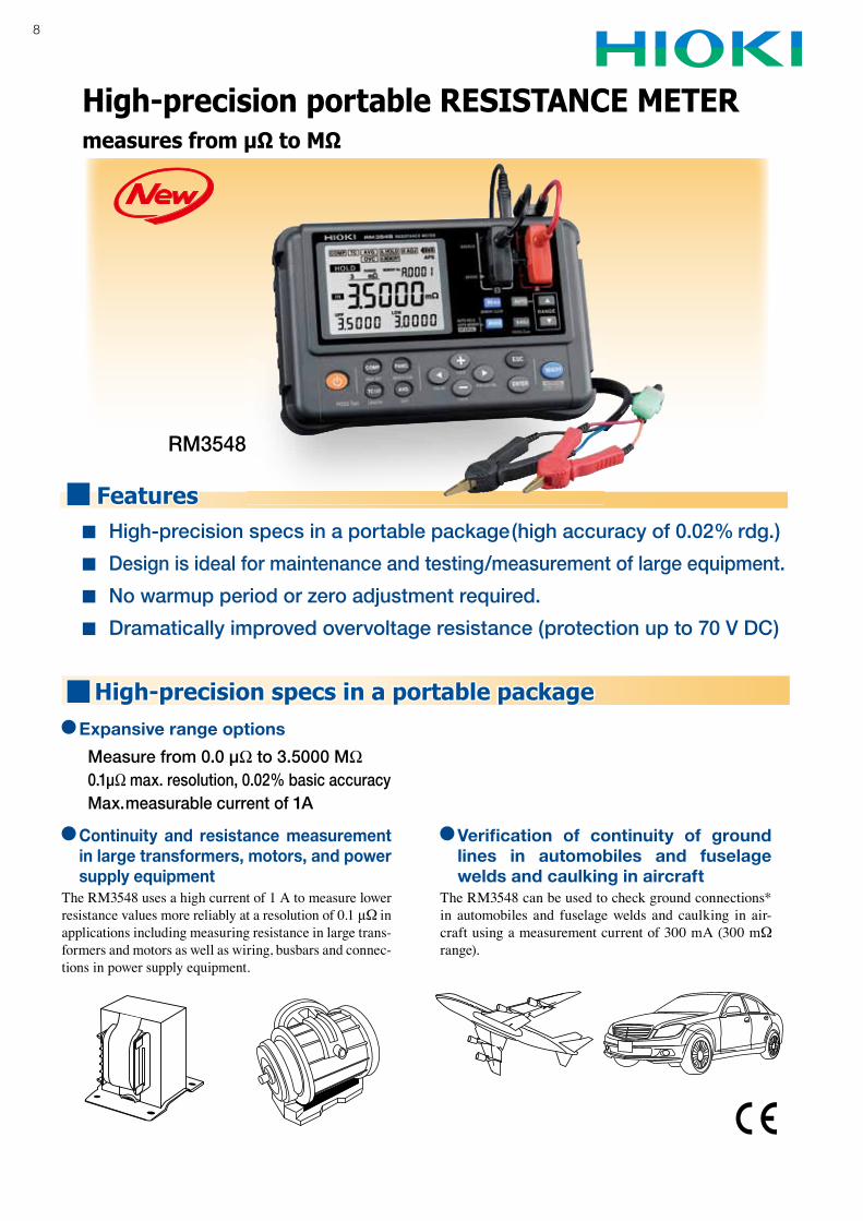
High-precision portable RESISTANCE METERmeasures from µΩ to MΩ
RM3548
High-precision specs in a portable package(high accuracy of 0.02% rdg.)
Design is ideal for maintenance and testing/measurement of large equipment.
No warmup period or zero adjustment required.
Dramatically improved overvoltage resistance (protection up to 70 V DC)
High-precision specs in a portable package Expansive range options
Measure from 0.0 µΩ to 3.5000 MΩ0.1µΩ max. resolution, 0.02% basic accuracyMax. measurable current of 1A
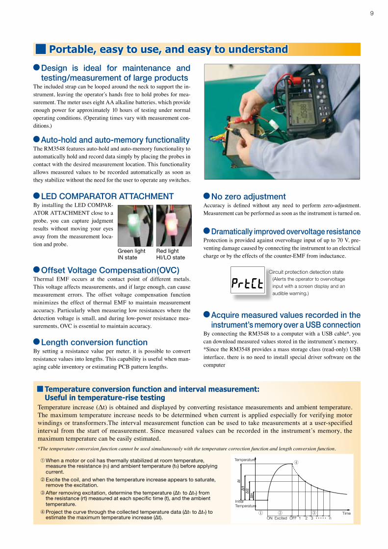
Continuity and resistance measurement in large transformers, motors, and power supply equipment
The RM3548 uses a high current of 1 A to measure lower resistance values more reliably at a resolution of 0.1 μΩ in applications including measuring resistance in large trans-formers and motors as well as wiring, busbars and connec-tions in power supply equipment.
Verification of continuity of ground lines in automobiles and fuselage welds and caulking in aircraft
The RM3548 can be used to check ground connections* in automobiles and fuselage welds and caulking in air-craft using a measurement current of 300 mA (300 mΩ range).
Features
9
Portable, easy to use, and easy to understand
Temperature conversion function and interval measurement:Useful in temperature-rise testing
Temperature increase (Δt) is obtained and displayed by converting resistance measurements and ambient temperature.The maximum temperature increase needs to be determined when current is applied especially for verifying motor windings or transformers.The interval measurement function can be used to take measurements at a user-specified interval from the start of measurement. Since measured values can be recorded in the instrument’s memory, the maximum temperature can be easily estimated.*The temperature conversion function cannot be used simultaneously with the temperature correction function and length conversion function.
➀ When a motor or coil has thermally stabilized at room temperature, measure the resistance (r0) and ambient temperature (t0) before applying current.
➁ Excite the coil, and when the temperature increase appears to saturate, remove the excitation.
➂ After removing excitation, determine the temperature (∆t1 to ∆tn) from the resistance (rt) measured at each specific time (t), and the ambient temperature.
➃ Project the curve through the collected temperature data (∆t1 to ∆tn) to estimate the maximum temperature increase (∆t).
Design is ideal for maintenance and testing/measurement of large products
The included strap can be looped around the neck to support the in-strument, leaving the operator’s hands free to hold probes for mea-surement. The meter uses eight AA alkaline batteries, which provide enough power for approximately 10 hours of testing under normal operating conditions. (Operating times vary with measurement con-ditions.)
Auto-hold and auto-memory functionalityThe RM3548 features auto-hold and auto-memory functionality to automatically hold and record data simply by placing the probes in contact with the desired measurement location. This functionality allows measured values to be recorded automatically as soon as they stabilize without the need for the user to operate any switches.
Offset Voltage Compensation(OVC)Thermal EMF occurs at the contact point of different metals. This voltage affects measurements, and if large enough, can cause measurement errors. The offset voltage compensation function minimizes the effect of thermal EMF to maintain measurement accuracy. Particularly when measuring low resistances where the detection voltage is small, and during low-power resistance mea-surements, OVC is essential to maintain accuracy.
Length conversion functionBy setting a resistance value per meter, it is possible to convert resistance values into lengths. This capability is useful when man-aging cable inventory or estimating PCB pattern lengths.
No zero adjustmentAccuracy is defi ned without any need to perform zero-adjustment. Measurement can be performed as soon as the instrument is turned on.
Acquire measured values recorded in the instrument’s memory over a USB connectionBy connecting the RM3548 to a computer with a USB cable*, you can download measured values stored in the instrument’s memory. *Since the RM3548 provides a mass storage class (read-only) USB interface, there is no need to install special driver software on the computer
By installing the LED COMPAR-ATOR ATTACHMENT close to a probe, you can capture judgment results without moving your eyes away from the measurement loca-tion and probe.
Green lightIN state
Red lightHI/LO state
Dramatically improved overvoltage resistanceProtection is provided against overvoltage input of up to 70 V, pre-venting damage caused by connecting the instrument to an electrical charge or by the effects of the counter-EMF from inductance.
Circuit protection detection state(Alerts the operator to overvoltage input with a screen display and an audible warning.)
TimeOFFON Excited
InitialTemperature
Temperature
1 2 3 n• • • • •
LED COMPARATOR ATTACHMENT
10
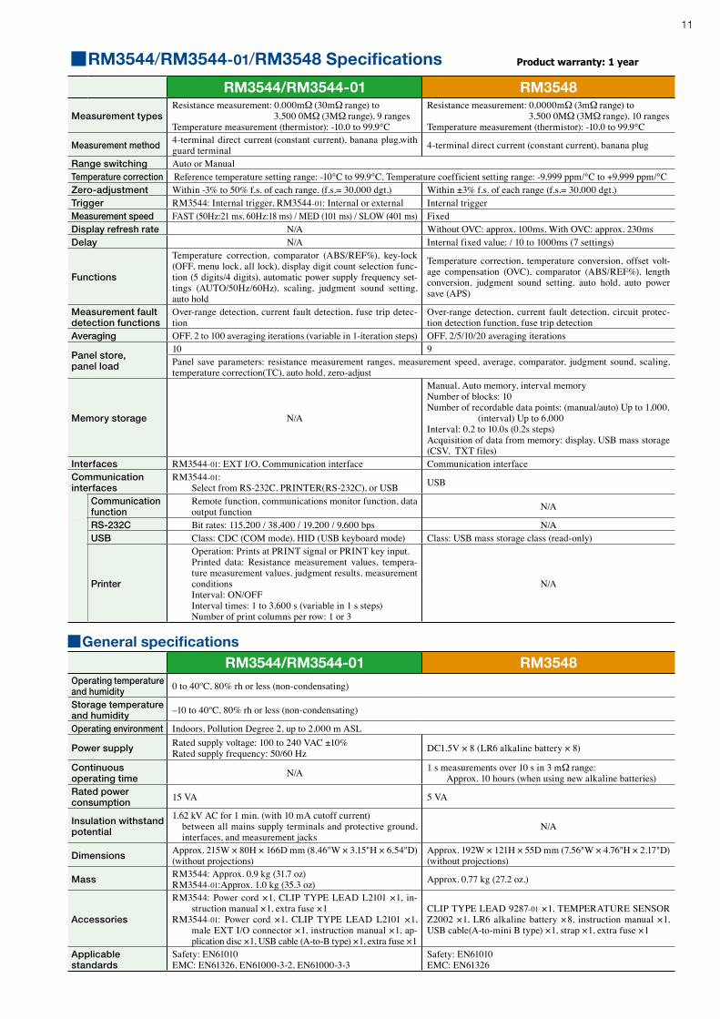
Measurement accuracy Resistance measurement accuracyConditions of guaranteed accuracy
• Temperature & humidity: 23 ˚C ±5 ˚C, 80% rh or less (non-condensating)• Guaranteed Accuracy Period: 1 year• From 0°C to 18°C and from 28°C to 40°C, add (temperature coefficient ±[1/10 measurement accuracy] / °C).
RM3548 Accuracy = ±(% rdg. + % f.s.)
(f.s. = calculated 30,000 dgt., where 0.010% f.s. = 3 dgt.)
RangeMax. measurement
display*4,*5 Accuracy*6 Measurement Current*7
Open-Circuit Voltage
3mΩ 3.500 0 mΩ 0.100 + 0.200 (0.100 + 0.020) 1A
5.5Vmax.
30mΩ 35.000 mΩ 0.100 + 0.020 (0.100 + 0.010)
300mΩ 350.00 mΩ 0.100 + 0.010 (0.100 + 0.010) 300mA0.020 + 0.020 (0.020 + 0.010) 100mA
3Ω 3.500 0 Ω 0.020 + 0.007 (0.020 + 0.007) 100mA30Ω 35.000 Ω 0.020 + 0.007 (0.020 + 0.007) 10mA
300Ω 350.00 Ω 0.020 + 0.007 (0.020 + 0.007)1mA3kΩ 3.500 0 kΩ 0.020 + 0.007
30kΩ 35.000 kΩ 0.020 + 0.007 100μA300kΩ 350.00 kΩ 0.040 + 0.007 5μA3MΩ 3.500 0 MΩ 0.200 + 0.007 500nA
*4 For negative values, to -10% f.s.*5 The maximum display range is the same as the maximum measurement range.*6 Measurement accuracy values assume offset voltage correction (OVC) is ON.*7 Measurement current accuracy is ±5%.
(Example) 0.020 + 0.007 . ..... 0.020% rdg. + 0.007% f.s.
* During temperature correction, the value calculated below is added to the rdg. error for resistance measurement accuracy:
t0 : Reference temperature. [ºC]t : Ambient temperature. [ºC]Δt : Temperature. measurement accuracyαt0 : Temperature. coefficient at t0 is [1/ºC]
-αt0 Δt1+ αt0 × (t+ Δt - t0)
×100 [%]
Temperature measurement accuracy• Temperature Sensor Z2001 (for RM3544/RM3544-01)• Temperature Sensor Z2002 (for RM3548)
Range of guaranteed accuracy -10.0 to 99.9 ºCDisplay refresh rate Approx. 2 sGuaranteed accuracy period 1 year
• Temperature Sensor Z2001 and RM3544/RM3544-01 combined accuracy• Temperature Sensor Z2002 and RM3548 combined accuracy
Temperature Accuracy -10.0 ºC to 9.9 ºC ± (0.55 + 0.009 × |t-10| ) ºC
10.0 ºC to 30.0 ºC ± 0.50 ºC30.1 ºC to 59.9 ºC ± (0.55 + 0.012 × |t-30| ) ºC60.0 ºC to 99.9 ºC ± (0.92 + 0.021 × |t-60| ) ºCStandalone instrument accuracy: ± 0.2 ºC
t: Temperature measurement values [ºC]
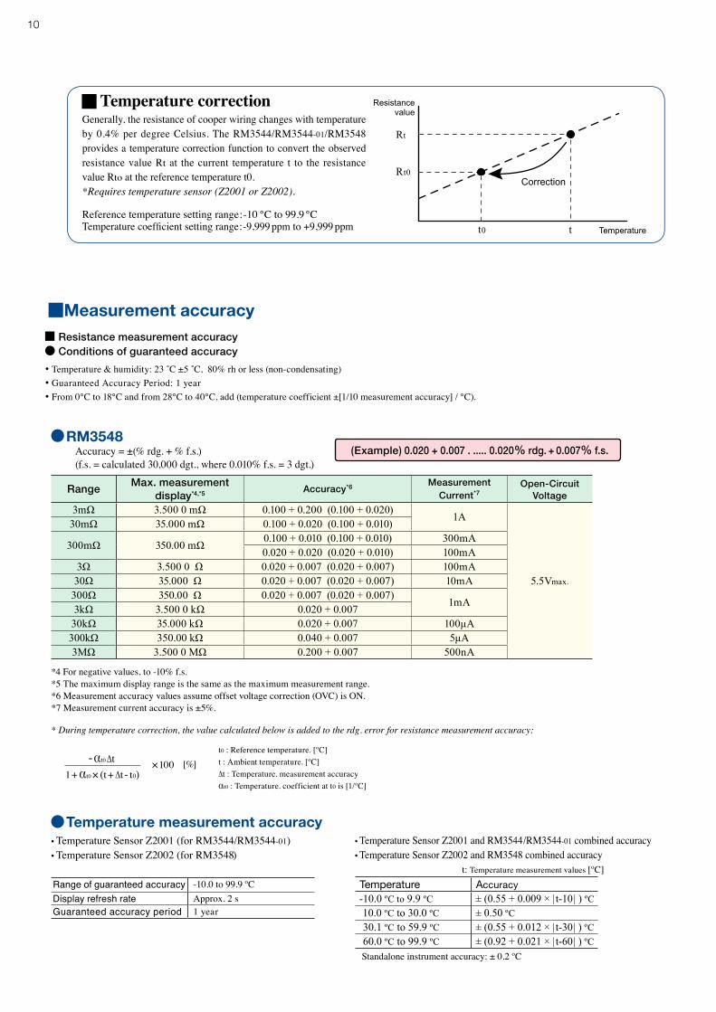
Temperature correctionGenerally, the resistance of cooper wiring changes with temperature by 0.4% per degree Celsius. The RM3544/RM3544-01/RM3548 provides a temperature correction function to convert the observed resistance value Rt at the current temperature t to the resistance value Rto at the reference temperature t0.*Requires temperature sensor (Z2001 or Z2002).
Reference temperature setting range:-10 to 99.9 Temperature coefficient setting range:-9,999 ppm to +9,999 ppm
Correction
Rt
Rt0
Resistancevalue
t0 t Temperature
11
General specificationsRM3544/RM3544-01 RM3548
Operating temperature and humidity 0 to 40ºC, 80% rh or less (non-condensating)
Storage temperature and humidity –10 to 40ºC, 80% rh or less (non-condensating)
Operating environment Indoors, Pollution Degree 2, up to 2,000 m ASL
Power supply Rated supply voltage: 100 to 240 VAC ±10%Rated supply frequency: 50/60 Hz DC1.5V × 8 (LR6 alkaline battery × 8)
Continuous operating time N/A 1 s measurements over 10 s in 3 mΩ range:
Approx. 10 hours (when using new alkaline batteries)Rated power consumption 15 VA 5 VA
Insulation withstand potential
1.62 kV AC for 1 min. (with 10 mA cutoff current) between all mains supply terminals and protective ground,
interfaces, and measurement jacksN/A
Dimensions Approx. 215W × 80H × 166D mm (8.46"W × 3.15"H × 6.54"D) (without projections)
Approx. 192W × 121H × 55D mm (7.56"W × 4.76"H × 2.17"D) (without projections)
Mass RM3544: Approx. 0.9 kg (31.7 oz) RM3544-01:Approx. 1.0 kg (35.3 oz) Approx. 0.77 kg (27.2 oz.)
Accessories
RM3544: Power cord ×1, CLIP TYPE LEAD L2101 ×1, in-struction manual ×1, extra fuse ×1
RM3544-01: Power cord ×1, CLIP TYPE LEAD L2101 ×1, male EXT I/O connector ×1, instruction manual ×1, ap-plication disc ×1, USB cable (A-to-B type) ×1, extra fuse ×1
CLIP TYPE LEAD 9287-01 ×1, TEMPERATURE SENSOR Z2002 ×1, LR6 alkaline battery ×8, instruction manual ×1, USB cable(A-to-mini B type) ×1, strap ×1, extra fuse ×1
Applicable standards
Safety: EN61010EMC: EN61326, EN61000-3-2, EN61000-3-3
Safety: EN61010EMC: EN61326
RM3544/RM3544-01 RM3548
Measurement typesResistance measurement: 0.000mΩ (30mΩ range) to 3.500 0MΩ (3MΩ range), 9 rangesTemperature measurement (thermistor): -10.0 to 99.9°C
Resistance measurement: 0.0000mΩ (3mΩ range) to 3.500 0MΩ (3MΩ range), 10 rangesTemperature measurement (thermistor): -10.0 to 99.9°C
Measurement method 4-terminal direct current (constant current), banana plug,with guard terminal 4-terminal direct current (constant current), banana plug
Range switching Auto or ManualTemperature correction Reference temperature setting range: -10°C to 99.9°C, Temperature coefficient setting range: -9,999 ppm/°C to +9,999 ppm/°C Zero-adjustment Within -3% to 50% f.s. of each range. (f.s.= 30,000 dgt.) Within ±3% f.s. of each range (f.s.= 30,000 dgt.)Trigger RM3544: Internal trigger, RM3544-01: Internal or external Internal triggerMeasurement speed FAST (50Hz:21 ms, 60Hz:18 ms) / MED (101 ms) / SLOW (401 ms) FixedDisplay refresh rate N/A Without OVC: approx. 100ms, With OVC: approx. 230msDelay N/A Internal fixed value: / 10 to 1000ms (7 settings)
Functions
Temperature correction, comparator (ABS/REF%), key-lock (OFF, menu lock, all lock), display digit count selection func-tion (5 digits/4 digits), automatic power supply frequency set-tings (AUTO/50Hz/60Hz), scaling, judgment sound setting, auto hold
Temperature correction, temperature conversion, offset volt-age compensation (OVC), comparator (ABS/REF%), length conversion, judgment sound setting, auto hold, auto power save (APS)
Measurement fault detection functions
Over-range detection, current fault detection, fuse trip detec-tion
Over-range detection, current fault detection, circuit protec-tion detection function, fuse trip detection
Averaging OFF, 2 to 100 averaging iterations (variable in 1-iteration steps) OFF, 2/5/10/20 averaging iterations
Panel store, panel load
10 9Panel save parameters: resistance measurement ranges, measurement speed, average, comparator, judgment sound, scaling, temperature correction(TC), auto hold, zero-adjust
Memory storage N/A
Manual, Auto memory, interval memoryNumber of blocks: 10Number of recordable data points: (manual/auto) Up to 1,000, (interval) Up to 6,000Interval: 0.2 to 10.0s (0.2s steps)Acquisition of data from memory: display, USB mass storage (CSV, TXT files)
Interfaces RM3544-01: EXT I/O, Communication interface Communication interfaceCommunication interfaces
RM3544-01: Select from RS-232C, PRINTER(RS-232C), or USB USB
Communication function
Remote function, communications monitor function, data output function N/A
RS-232C Bit rates: 115,200 / 38,400 / 19,200 / 9,600 bps N/AUSB Class: CDC (COM mode), HID (USB keyboard mode) Class: USB mass storage class (read-only)
Printer
Operation: Prints at PRINT signal or PRINT key input. Printed data: Resistance measurement values, tempera-
ture measurement values, judgment results, measurement conditions
Interval: ON/OFF Interval times: 1 to 3,600 s (variable in 1 s steps) Number of print columns per row: 1 or 3
N/A
RM3544/RM3544-01/RM3548 Specifications Product warranty: 1 year
HEADQUARTERS:81 Koizumi, Ueda, Nagano, 386-1192, JapanTEL +81-268-28-0562 FAX +81-268-28-0568 http://www.hioki.com / E-mail: [email protected]
HIOKI USA CORPORATION:TEL +1-609-409-9109 FAX +1-609-409-9108http://www.hiokiusa.com / E-mail: [email protected]
All information correct as of Jan. 15, 2013. All specifications are subject to change without notice.
Note: Company names and Product names appearing in this catalog are trademarks or registered trademarks of various companies.
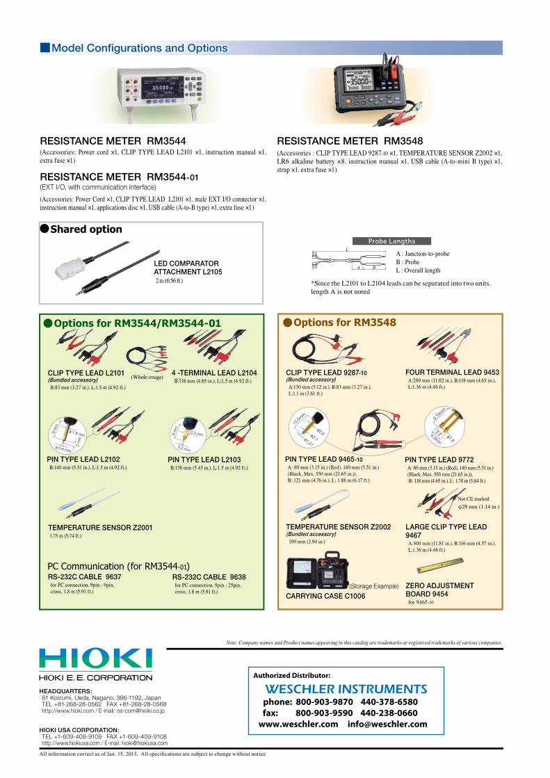
Model Configurations and Options
RESISTANCE METER RM3544(Accessories: Power cord ×1, CLIP TYPE LEAD L2101 ×1, instruction manual ×1, extra fuse ×1)
RESISTANCE METER RM3544-01(EXT I/O, with communication interface)
(Accessories: Power Cord ×1, CLIP TYPE LEAD L2101 ×1, male EXT I/O connector ×1, instruction manual ×1, applications disc ×1, USB cable (A-to-B type) ×1, extra fuse ×1)
RESISTANCE METER RM3548(Accessories : CLIP TYPE LEAD 9287-10 ×1, TEMPERATURE SENSOR Z2002 ×1, LR6 alkaline battery ×8, instruction manual ×1, USB cable (A-to-mini B type) ×1, strap ×1, extra fuse ×1)
Probe Lengths
A : Junction-to-probeB : ProbeL : Overall length
*Since the L2101 to L2104 leads can be separated into two units, length A is not noted
LED COMPARATOR ATTACHMENT L21052 m (6.56 ft.)
Options for RM3544/RM3544-01
RS-232C CABLE 9637for PC connection, 9pin - 9pin, cross, 1.8 m (5.91 ft.)
RS-232C CABLE 9638for PC connection, 9pin - 25pin, cross, 1.8 m (5.91 ft.)
PC Communication (for RM3544-01)
TEMPERATURE SENSOR Z2001 1.75 m (5.74 ft.)
4 -TERMINAL LEAD L2104B:118 mm (4.65 in.), L:1.5 m (4.92 ft.)
CLIP TYPE LEAD L2101(Bundled accessory)
B:83 mm (3.27 in.), L:1.5 m (4.92 ft.)
(Whole image)
PIN TYPE LEAD L2102 B:140 mm (5.51 in.), L:1.5 m (4.92 ft.)
PIN TYPE LEAD L2103 B:138 mm (5.43 in.), L:1.5 m (4.92 ft.)
Options for RM3548
FOUR TERMINAL LEAD 9453A:280 mm (11.02 in.), B:118 mm (4.65 in.), L:1.36 m (4.46 ft.)
LARGE CLIP TYPE LEAD 9467
A:300 mm (11.81 in.), B:116 mm (4.57 in.), L:1.36 m (4.46 ft.)
φ29 mm (1.14 in.)Not CE marked
PIN TYPE LEAD 9772A: 80 mm (3.15 in.) (Red), 140 mm (5.51 in.) (Black, Max. 550 mm (21.65 in.)), B: 118 mm (4.65 in.), L: 1.78 m (5.84 ft.)
PIN TYPE LEAD 9465-10A: 80 mm (3.15 in.) (Red), 140 mm (5.51 in.) (Black, Max. 550 mm (21.65 in.)), B: 121 mm (4.76 in.), L: 1.88 m (6.17 ft.)
CLIP TYPE LEAD 9287-10(Bundled accessory)
A:130 mm (5.12 in.), B:83 mm (3.27 in.), L:1.1 m (3.61 ft.)
ZERO ADJUSTMENT BOARD 9454for 9465-10
TEMPERATURE SENSOR Z2002(Bundled accessory)
100 mm (3.94 in.)
CARRYING CASE C1006(Storage Example)
Shared option
phone: 800-903-9870 440-378-6580 fax: 800-903-9590 440-238-0660
www.weschler.com [email protected]
WESCHLER INSTRUMENTSAuthorized Distributor: