Highly accurate, rigid LINEAR SLIDE CYLINDER LCG SERIES · Linear slide cylinder LCG Series Option...
67
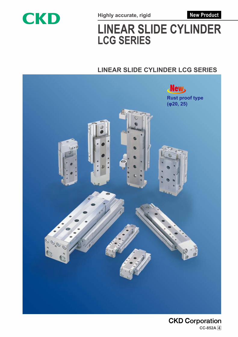
LINEAR SLIDE CYLINDER LCG SERIES LINEAR SLIDE CYLINDER LCG SERIES Highly accurate, rigid CC-852A 4 Rust proof type (φ20, 25)
Transcript of Highly accurate, rigid LINEAR SLIDE CYLINDER LCG SERIES · Linear slide cylinder LCG Series Option...
LINEAR SLIDE CYLINDERLCG SERIES
LINEAR SLIDE CYLINDER LCG SERIES
Highly accurate, rigid
CC-852A 4
Rust proof type(φ20, 25)
10 20 30 40 50 75 100 125 150
LCG-Q
LCG
Stroke(mm) w/ bufferBore size
LCG-P7※
■LCG Series productsModel variation
B※
φ6φ8φ12φ16
φ6φ8φ12φ16φ20・φ25
φ20・φ25
φ20・φ25
φ8φ12φ16
Rust proof
U
Change to symmetrical Arrows ( ) show the piping direction.
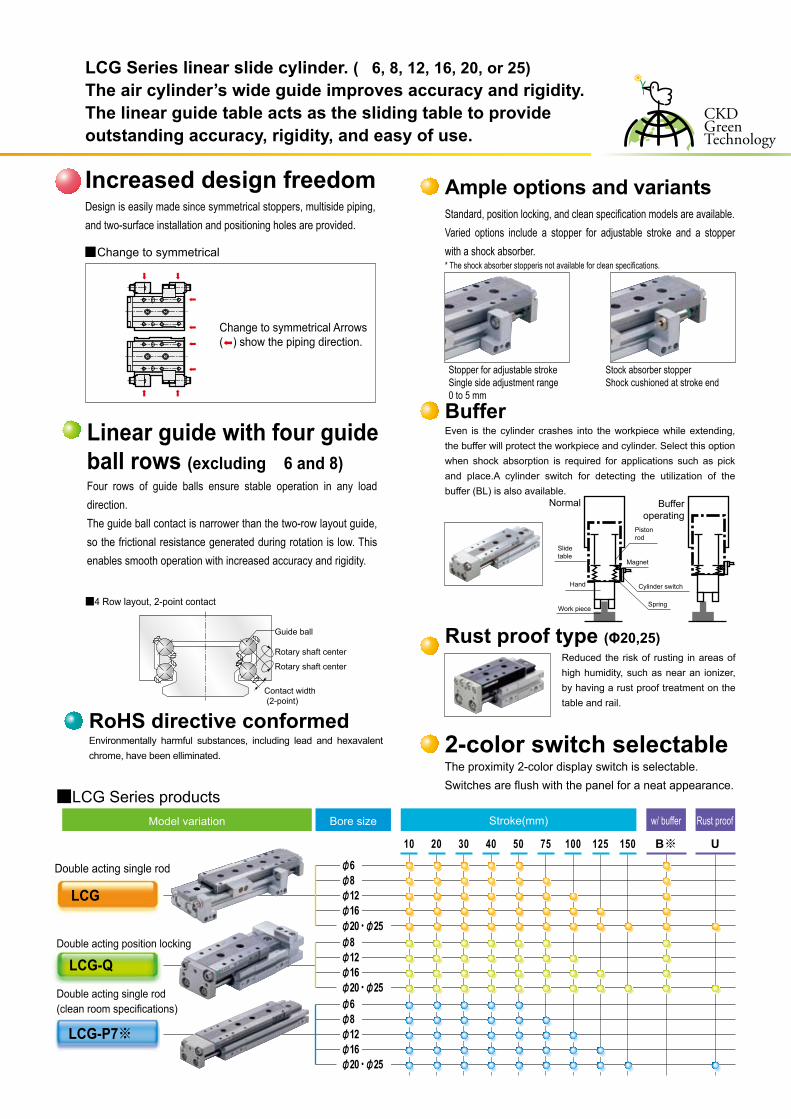
Increased design freedomDesign is easily made since symmetrical stoppers, multiside piping, and two-surface installation and positioning holes are provided.
Change to symmetrical
LCG Series linear slide cylinder. ( 6, 8, 12, 16, 20, or 25)The air cylinder’s wide guide improves accuracy and rigidity.The linear guide table acts as the sliding table to provide outstanding accuracy, rigidity, and easy of use.
Double acting single rod
Double acting position locking
Double acting single rod (clean room specifications)
Ample options and variants
Rust proof type (Φ20,25)
BufferEven is the cylinder crashes into the workpiece while extending, the buffer will protect the workpiece and cylinder. Select this option when shock absorption is required for applications such as pick and place.A cylinder switch for detecting the utilization of the buffer (BL) is also available.
Reduced the risk of rusting in areas of high humidity, such as near an ionizer, by having a rust proof treatment on the table and rail.
RoHS directive conformedEnvironmentally harmful substances, including lead and hexavalent chrome, have been elliminated.
■4 Row layout, 2-point contact
Guide ball
Rotary shaft center
Contact width (2-point)
Rotary shaft center
Slidetable
Hand
Work piece
Pistonrod
Magnet
Cylinder switch
Spring
Normal Bufferoperating
Applications
Radial moment
Load moment (N m)
Displa
cement
15 30
0.05
(mm)
Storage of small parts in trayor removal of parts from tray
Feeding of small parts
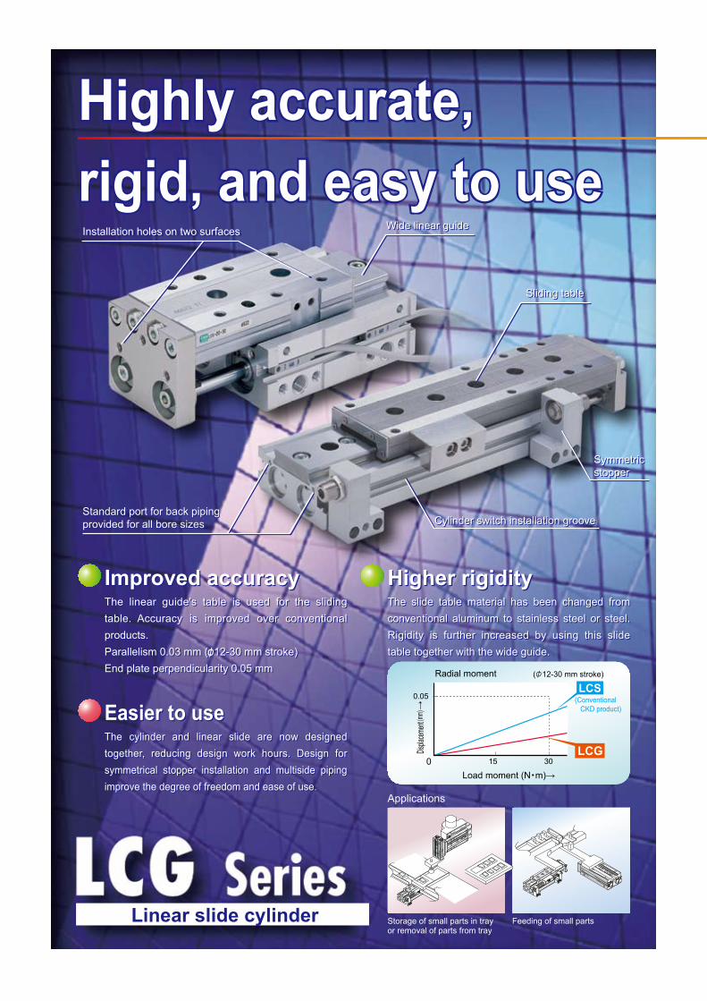
Highly accurate,rigid, and easy to use
Sliding table
Wide linear guide
Standard port for back pipingprovided for all bore sizes
Symmetricstopper
LCG0
( 12-30 mm stroke)
LCS(Conventional CKD product)
Highly accurate,rigid, and easy to useHighly accurate,rigid, and easy to use
Installation holes on two surfacesInstallation holes on two surfaces Wide linear guide
Sliding table
Standard port for back pipingprovided for all bore sizes
Symmetricstopper
Cylinder switch installation grooveCylinder switch installation groove
The linear guide's table is used for the sliding table. Accuracy is improved over conventional products.Parallelism 0.03 mm ( 12-30 mm stroke)End plate perpendicularity 0.05 mm
Improved accuracyImproved accuracyThe linear guide's table is used for the sliding table. Accuracy is improved over conventional products.Parallelism 0.03 mm ( 12-30 mm stroke)End plate perpendicularity 0.05 mm
The cylinder and linear slide are now designed together, reducing design work hours. Design for symmetrical stopper installation and multiside piping improve the degree of freedom and ease of use.
Easier to useEasier to useThe cylinder and linear slide are now designed together, reducing design work hours. Design for symmetrical stopper installation and multiside piping improve the degree of freedom and ease of use.
Higher rigidityHigher rigidityThe slide table material has been changed from conventional aluminum to stainless steel or steel. Rigidity is further increased by using this slide table together with the wide guide.
The slide table material has been changed from conventional aluminum to stainless steel or steel. Rigidity is further increased by using this slide table together with the wide guide.
Linear slide cylinder
Four rows of guide balls ensure stable operation in any load direction.The guide ball contact is narrower than the two-row layout guide, so the frictional resistance generated during rotation is low. This enables smooth operation with increased accuracy and rigidity.
Linear guide with four guideball rows (excluding 6 and 8)
2-color switch selectableThe proximity 2-color display switch is selectable.Switches are flush with the panel for a neat appearance.
Stopper for adjustable strokeSingle side adjustment range 0 to 5 mm
Stock absorber stopperShock cushioned at stroke end
Standard, position locking, and clean specification models are available.Varied options include a stopper for adjustable stroke and a stopper with a shock absorber.* The shock absorber stopperis not available for clean specifications.
10 20 30 40 50 75 100 125 150
LCG-Q
LCG
Stroke(mm) w/ bufferBore size
LCG-P7※
■LCG Series productsModel variation
B※
φ6φ8φ12φ16
φ6φ8φ12φ16φ20・φ25
φ20・φ25
φ20・φ25
φ8φ12φ16
Rust proof
U
Change to symmetrical Arrows ( ) show the piping direction.
Increased design freedomDesign is easily made since symmetrical stoppers, multiside piping, and two-surface installation and positioning holes are provided.
Change to symmetrical
LCG Series linear slide cylinder. ( 6, 8, 12, 16, 20, or 25)The air cylinder’s wide guide improves accuracy and rigidity.The linear guide table acts as the sliding table to provide outstanding accuracy, rigidity, and easy of use.
Double acting single rod
Double acting position locking
Double acting single rod (clean room specifications)
Ample options and variants
Rust proof type (Φ20,25)
BufferEven is the cylinder crashes into the workpiece while extending, the buffer will protect the workpiece and cylinder. Select this option when shock absorption is required for applications such as pick and place.A cylinder switch for detecting the utilization of the buffer (BL) is also available.
Reduced the risk of rusting in areas of high humidity, such as near an ionizer, by having a rust proof treatment on the table and rail.
RoHS directive conformedEnvironmentally harmful substances, including lead and hexavalent chrome, have been elliminated.
■4 Row layout, 2-point contact
Guide ball
Rotary shaft center
Contact width (2-point)
Rotary shaft center
Slidetable
Hand
Work piece
Pistonrod
Magnet
Cylinder switch
Spring
Normal Bufferoperating
Applications
Radial moment
Load moment (N m)
Displa
cement
15 30
0.05
(mm)
Storage of small parts in trayor removal of parts from tray
Feeding of small parts
Highly accurate,rigid, and easy to use
Sliding table
Wide linear guide
Standard port for back pipingprovided for all bore sizes
Symmetricstopper
LCG0
( 12-30 mm stroke)
LCS(Conventional CKD product)
Highly accurate,rigid, and easy to useHighly accurate,rigid, and easy to use
Installation holes on two surfacesInstallation holes on two surfaces Wide linear guide
Sliding table
Standard port for back pipingprovided for all bore sizes
Symmetricstopper
Cylinder switch installation grooveCylinder switch installation groove
The linear guide's table is used for the sliding table. Accuracy is improved over conventional products.Parallelism 0.03 mm ( 12-30 mm stroke)End plate perpendicularity 0.05 mm
Improved accuracyImproved accuracyThe linear guide's table is used for the sliding table. Accuracy is improved over conventional products.Parallelism 0.03 mm ( 12-30 mm stroke)End plate perpendicularity 0.05 mm
The cylinder and linear slide are now designed together, reducing design work hours. Design for symmetrical stopper installation and multiside piping improve the degree of freedom and ease of use.
Easier to useEasier to useThe cylinder and linear slide are now designed together, reducing design work hours. Design for symmetrical stopper installation and multiside piping improve the degree of freedom and ease of use.
Higher rigidityHigher rigidityThe slide table material has been changed from conventional aluminum to stainless steel or steel. Rigidity is further increased by using this slide table together with the wide guide.
The slide table material has been changed from conventional aluminum to stainless steel or steel. Rigidity is further increased by using this slide table together with the wide guide.
Linear slide cylinder
Four rows of guide balls ensure stable operation in any load direction.The guide ball contact is narrower than the two-row layout guide, so the frictional resistance generated during rotation is low. This enables smooth operation with increased accuracy and rigidity.
Linear guide with four guideball rows (excluding 6 and 8)
2-color switch selectableThe proximity 2-color display switch is selectable.Switches are flush with the panel for a neat appearance.
Stopper for adjustable strokeSingle side adjustment range 0 to 5 mm
Stock absorber stopperShock cushioned at stroke end
Standard, position locking, and clean specification models are available.Varied options include a stopper for adjustable stroke and a stopper with a shock absorber.* The shock absorber stopperis not available for clean specifications.
Seriesvariation
Linear slide cylinderLCG Series
Option
Sw
itch
Pag
e
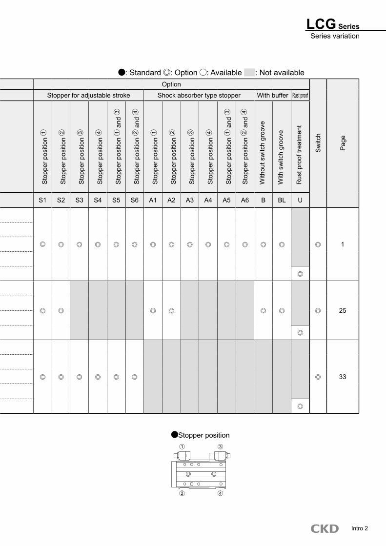
Stopper for adjustable stroke Shock absorber type stopper With buffer Rust proof
Variation Model no.
JIS symbol
Bore size
(mm)
Stroke length (mm)
Sto
pper
pos
ition
1
Sto
pper
pos
ition
2
Sto
pper
pos
ition
3
Sto
pper
pos
ition
4
Sto
pper
pos
ition
1 a
nd 3
Sto
pper
pos
ition
2 a
nd 4
Sto
pper
pos
ition
1
Sto
pper
pos
ition
2
Sto
pper
pos
ition
3
Sto
pper
pos
ition
4
Sto
pper
pos
ition
1 a
nd 3
Sto
pper
pos
ition
2 a
nd 4
W
ithou
t sw
itch
groo
ve
W
ith s
witc
h gr
oove
R
ust p
roof
trea
tmen
t
10 20 30 40 50 75 100 125 150 S1 S2 S3 S4 S5 S6 A1 A2 A3 A4 A5 A6 B BL U
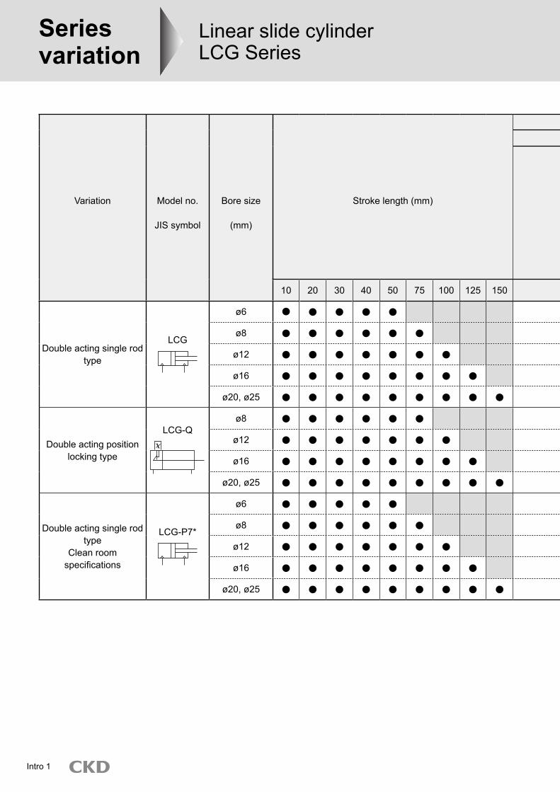
Double acting single rod type
LCG
ø6
1
ø8
ø12
ø16
ø20, ø25
Double acting position locking type
LCG-Qø8
25ø12
ø16
ø20, ø25
Double acting single rod type
Clean room specifications
LCG-P7*
ø6
33
ø8
ø12
ø16
ø20, ø25
Intro 1
LCG SeriesSeries variation
Option
Sw
itch
Pag
e
Stopper for adjustable stroke Shock absorber type stopper With buffer Rust proof
Variation Model no.
JIS symbol
Bore size
(mm)
Stroke length (mm)
Sto
pper
pos
ition
1
Sto
pper
pos
ition
2
Sto
pper
pos
ition
3
Sto
pper
pos
ition
4
Sto
pper
pos
ition
1 a
nd 3
Sto
pper
pos
ition
2 a
nd 4
Sto
pper
pos
ition
1
Sto
pper
pos
ition
2
Sto
pper
pos
ition
3
Sto
pper
pos
ition
4
Sto
pper
pos
ition
1 a
nd 3
Sto
pper
pos
ition
2 a
nd 4
W
ithou
t sw
itch
groo
ve
W
ith s
witc
h gr
oove
R
ust p
roof
trea
tmen
t
10 20 30 40 50 75 100 125 150 S1 S2 S3 S4 S5 S6 A1 A2 A3 A4 A5 A6 B BL U
Double acting single rod type
LCG
ø6
1
ø8
ø12
ø16
ø20, ø25
Double acting position locking type
LCG-Qø8
25ø12
ø16
ø20, ø25
Double acting single rod type
Clean room specifications
LCG-P7*
ø6
33
ø8
ø12
ø16
ø20, ø25
: Standard : Option : Available : Not available
Intro 2
2 4
1 3
Stopper position
Safety precautionsAlways read this section before starting use.
When designing and manufacturing a device using CKD products, the manufacturer is obligated to check that device safety mechanical mechanism, pneumatic control circuit, or water control circuit and the system operated by electrical control that controls the devices is secured.It is important to select, use, handle, and maintain the product appropriately to ensure that the CKD product is used safely.Observe warnings and precautions to ensure device safety.Check that device safety is ensured, and manufacture a safe device.
WARNING1 This product is designed and manufactured as a general industrial machine part. It must
be handled by an operator having sufficient knowledge and experience in handling.
2 Use this product in accordance of specifications.This product must be used within its stated specifications. It must not be modified or machined.This product is intended for use as a general-purpose industrial device or part. It is not intended for use outdoors or for use under the following conditions or environment.Note that this product can be used when CKD is consulted prior to use and the customer consents to CKD product specifications. The customer must provide safety measures to avoid risks in the event of problems.1 Use for special applications requiring safety including nuclear energy, railroad, aviation, ship, vehicle, medical equipment, equipment, or applications
coming into contact with beverage or food, amusement equipment, emergency shutoff circuits, press machine, brake circuits, or for safeguard.2 Use for applications where life or assets could be adversely affected, and special safety measures are required.
3 Observe corporate standards and regulations, etc., related to the safety of device design and control, etc.ISO 4414, JIS B 8370 (pneumatic system rules)JFPS 2008 (principles for pneumatic cylinder selection and use)Including High Pressure Gas Maintenance Law, Occupational Safety and Sanitation Laws, other safety rules, body standards and regulations, etc.
4 Do not handle, pipe, or remove devices before confirming safety.1 Inspect and service the machine and devices after confirming safety of the entire system related to this
product.2 Note that there may be hot or charged sections even after operation is stopped.3 When inspecting or servicing the device, turn off the energy source (air supply or water supply), and turn off power to the facility.
Discharge any compressed air from the system, and pay enough attention to possible water leakage and leakage of electricity.4 When starting or restarting a machine or device that incorporates pneumatic components, make sure that
the system safety, such as pop-out prevention measures, is secured.
5 Observe warnings and cautions on the pages below to prevent accidents. The safety cautions are ranked as “DANGER”, “WARNING” and “CAUTION” in this section.
DANGER: When a dangerous situation may occur if handling is mistaken leading to fatal or serious injuries, or when there is a high degree of emergency to a warning.
WARNING: When a dangerous situation may occur if handling is mistaken leading to fatal or serious injuries.
CAUTION: When a dangerous situation may occur if handling is mistaken leading to minor injuries or physical damage.
Note that some items described as “CAUTION” may lead to serious results depending on the situation. In any case, important information that must be observed is explained.
Disclaimer1. CKD cannot be held liable for any business interruption, loss of profit, personal injury, delay cost, or any other an-
cillary or indirect loss, cost, or damage resulting from the use of or faults in the use of CKD products.2. CKD cannot be held responsible for the following damage:
1 Damage resulting from failure of CKD parts due to fire from reasons not attributable to CKD, or by intentional or negligence of a third party or customer.
2 When a CKD product is assembled into customer equipment, damage that could have been avoided if customer equipment were provided with functions and structure, etc., generally accepted in the industry.
3 Damage resulting from use exceeding the scope of specifications provided in CKD catalogs or instruction man-uals, etc., or from actions not following precautions for installation, adjustment, or maintenance, etc.
4 Damage resulting from production modifications not approved by CKD, or from faults due to combination with other software or other connected devices.
Intro 3
Pneumatic components
Safety precautionsAlways read this section before starting use.Refer to Pneumatic cylinders (CB-029SA) for the general details on cylinders and cylinder switch.
CAUTION Refer to the LCG Selection Guide on pages 47 to 50 when selecting the cylinder.
When using the cylinder where it could be subject to wa-ter or oil exposure, where it could corrode, or where high levels of dust are present, the cylinder could be dam-aged or malfunction. Protect the product with a cover.
Precautions for using type with switch When using the T*V switch with the cylinder with a stop-per for adjustable stroke (S3**, S4**, S5**, S6**) or shock absorber stopper (A3**, A4**, A5**, A6**), the head side switch could interfere with the stopper. Install the switch on the side opposite the stopper.
1. Common
CAUTION Do not use a 3-position valve.Do not use this cylinder with a 3-position valve, especially with a closed center metal seal. The lock is not applied if pressure is sealed on the port having the lock. Even if the lock is applied, air leaking from the valve may enter the cyl-inder or the lock may be released over time.
2. Position locking type LCG-Q
Design & Selection
CAUTION When changing a piping port position, apply adhe-sive to M3 and M5 plug (hexagon socket head set screw). (Low intensity adhesive such as LOCTITE 222, 221, THREE BOND 1344 recommended)
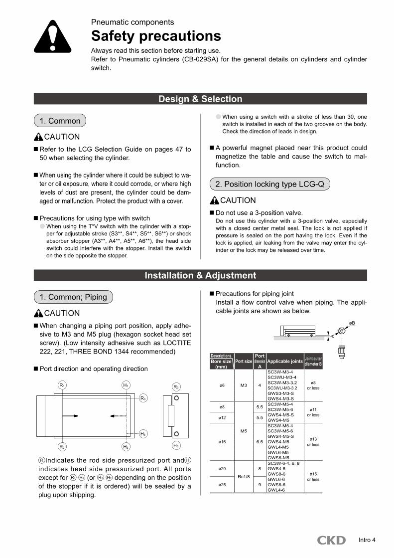
Port direction and operating direction
1. Common; Piping
Installation & Adjustment
DescriptionsPort size
Port dimension
AApplicable joints Joint outer
diameter BBore size (mm)
ø6 M3 4
SC3W-M3-4
ø8or less
SC3WU-M3-4SC3W-M3-3.2SC3WU-M3-3.2GWS3-M3-SGWS4-M3-S
ø8
M5
5.5 SC3W-M5-4ø11
or lessSC3W-M5-6
ø12 5.5 GWS4-M5-SGWS4-M5
ø16 6.5
SC3W-M5-4
ø13or less
SC3W-M5-6GWS4-M5-SGWS4-M5GWL4-M5GWL6-M5GWS6-M5
ø20
Rc1/8
8SC3W-6-4, 6, 8
ø15or less
GWS4-6GWS8-6
ø25 9GWL6-6GWS6-6GWL4-6
When using a switch with a stroke of less than 30, one switch is installed in each of the two grooves on the body. Check the direction of leads in design.
A powerful magnet placed near this product could magnetize the table and cause the switch to mal-function.
Precautions for piping jointInstall a flow control valve when piping. The appli-cable joints are shown as below.
Intro 4
R Indicates the rod side pressurized port and H indicates head side pressurized port. All ports except for R1 H1 (or R2 H2 depending on the position of the stopper if it is ordered) will be sealed by a plug upon shipping.
R1 H1
R2 H2
H3
R3
R3
H3
øB
A
LCG Series
Installation & Adjustment
DescriptionsTable
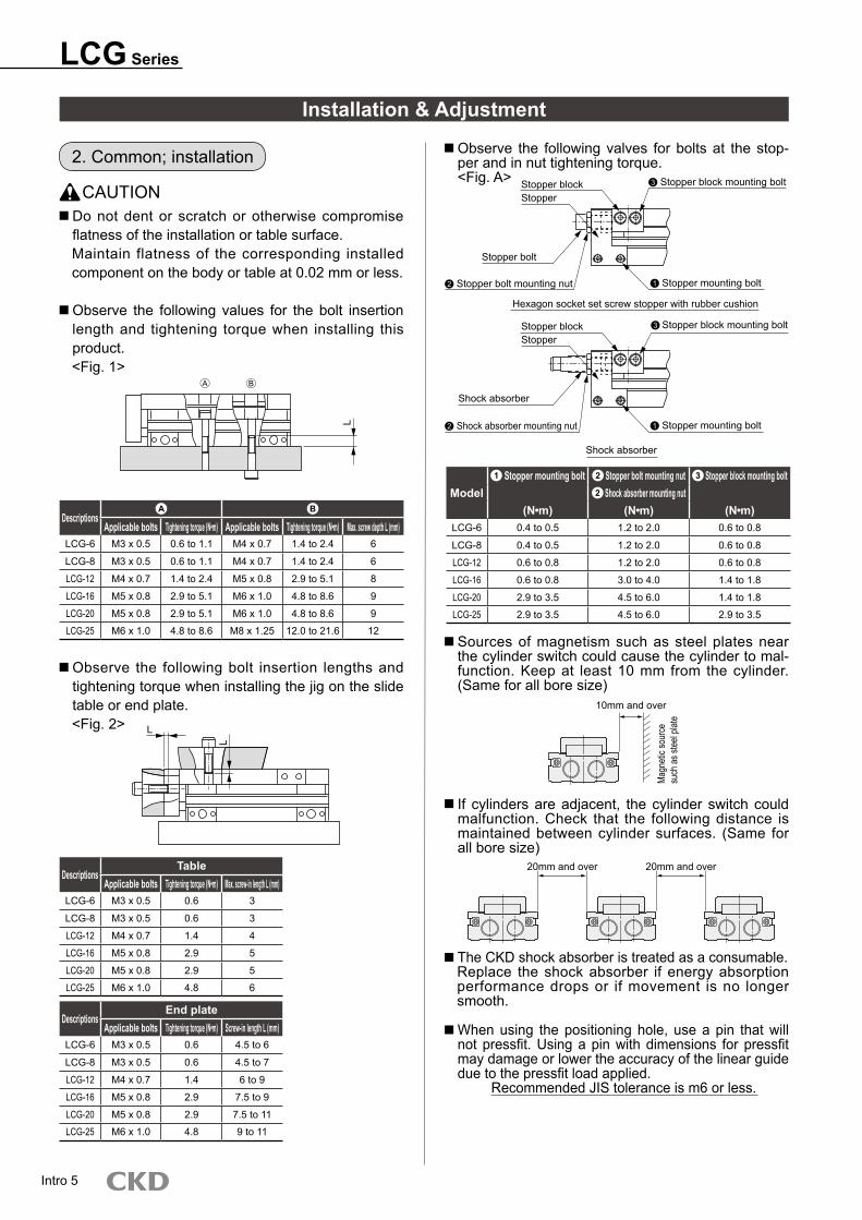
Applicable bolts Tightening torque (N m) Max. screw-in length L (mm)LCG-6 M3 x 0.5 0.6 3
LCG-8 M3 x 0.5 0.6 3
LCG-12 M4 x 0.7 1.4 4
LCG-16 M5 x 0.8 2.9 5
LCG-20 M5 x 0.8 2.9 5
LCG-25 M6 x 1.0 4.8 6
Observe the following bolt insertion lengths and tightening torque when installing the jig on the slide table or end plate.<Fig. 2>
Observe the following valves for bolts at the stop-per and in nut tightening torque.<Fig. A>
Model1 Stopper mounting bolt 2 Stopper bolt mounting nut 3 Stopper block mounting bolt
2 Shock absorber mounting nut(N m) (N m) (N m)
LCG-6 0.4 to 0.5 1.2 to 2.0 0.6 to 0.8
LCG-8 0.4 to 0.5 1.2 to 2.0 0.6 to 0.8
LCG-12 0.6 to 0.8 1.2 to 2.0 0.6 to 0.8
LCG-16 0.6 to 0.8 3.0 to 4.0 1.4 to 1.8
LCG-20 2.9 to 3.5 4.5 to 6.0 1.4 to 1.8
LCG-25 2.9 to 3.5 4.5 to 6.0 2.9 to 3.5
Sources of magnetism such as steel plates near the cylinder switch could cause the cylinder to mal-function. Keep at least 10 mm from the cylinder. (Same for all bore size)
If cylinders are adjacent, the cylinder switch could malfunction. Check that the following distance is maintained between cylinder surfaces. (Same for all bore size)
The CKD shock absorber is treated as a consumable.Replace the shock absorber if energy absorption performance drops or if movement is no longer smooth.
When using the positioning hole, use a pin that will not pressfit. Using a pin with dimensions for pressfit may damage or lower the accuracy of the linear guide due to the pressfit load applied.
Recommended JIS tolerance is m6 or less.
DescriptionsEnd plate
Applicable bolts Tightening torque (N m) Screw-in length L (mm)LCG-6 M3 x 0.5 0.6 4.5 to 6
LCG-8 M3 x 0.5 0.6 4.5 to 7
LCG-12 M4 x 0.7 1.4 6 to 9
LCG-16 M5 x 0.8 2.9 7.5 to 9
LCG-20 M5 x 0.8 2.9 7.5 to 11
LCG-25 M6 x 1.0 4.8 9 to 11
CAUTION Do not dent or scratch or otherwise compromise flatness of the installation or table surface.Maintain flatness of the corresponding installed component on the body or table at 0.02 mm or less.
Observe the following values for the bolt insertion length and tightening torque when installing this product.<Fig. 1>
2. Common; installation
DescriptionsA B
Applicable bolts Tightening torque (N m) Applicable bolts Tightening torque (N m) Max. screw depth L (mm)LCG-6 M3 x 0.5 0.6 to 1.1 M4 x 0.7 1.4 to 2.4 6
LCG-8 M3 x 0.5 0.6 to 1.1 M4 x 0.7 1.4 to 2.4 6
LCG-12 M4 x 0.7 1.4 to 2.4 M5 x 0.8 2.9 to 5.1 8
LCG-16 M5 x 0.8 2.9 to 5.1 M6 x 1.0 4.8 to 8.6 9
LCG-20 M5 x 0.8 2.9 to 5.1 M6 x 1.0 4.8 to 8.6 9
LCG-25 M6 x 1.0 4.8 to 8.6 M8 x 1.25 12.0 to 21.6 12
Intro 5
L
L
Stopper blockStopper
Stopper bolt
2 Stopper bolt mounting nut
3 Stopper block mounting bolt
1 Stopper mounting bolt
Hexagon socket set screw stopper with rubber cushion
3 Stopper block mounting boltStopper blockStopper
Shock absorber
Shock absorber
1 Stopper mounting bolt2 Shock absorber mounting nut
10mm and over
Mag
netic
sour
ce
such
as s
teel
plate
20mm and over 20mm and over
A B
L
LCG Series
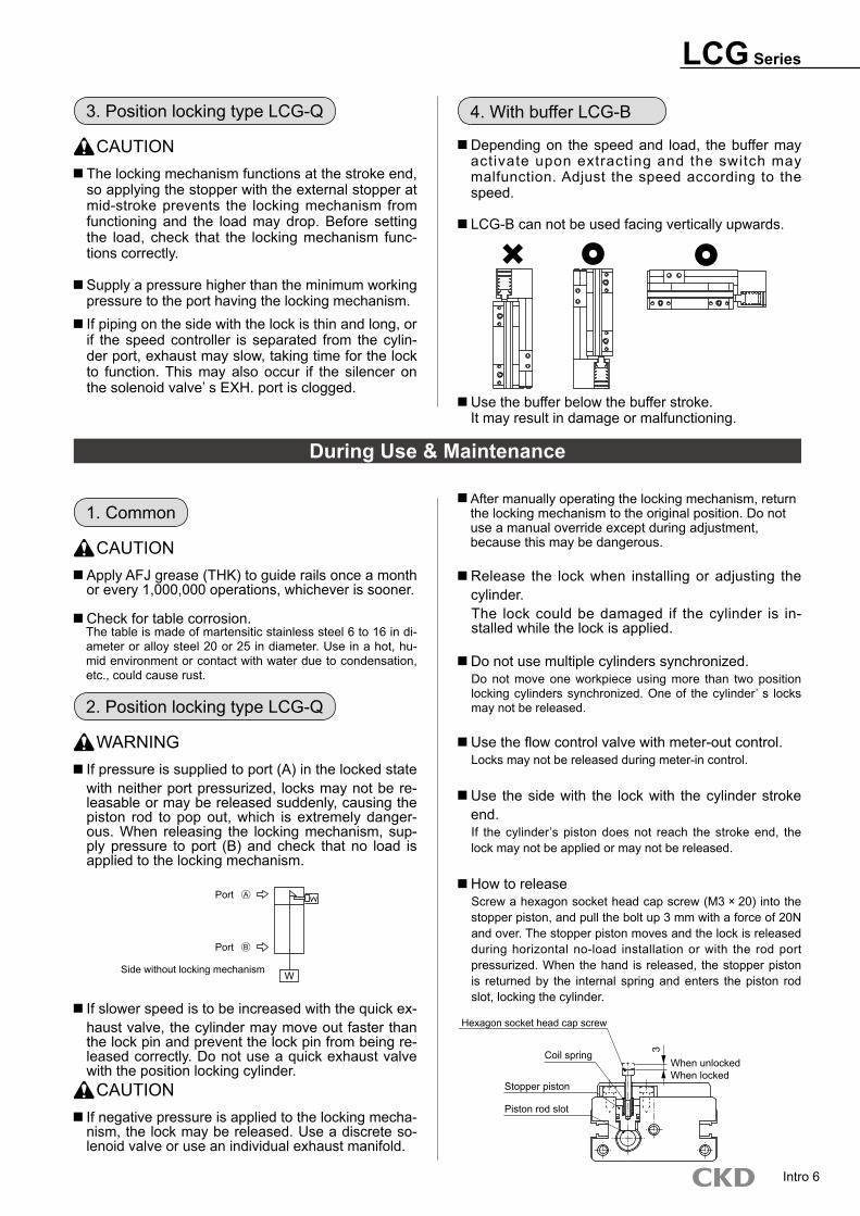
CAUTION The locking mechanism functions at the stroke end, so applying the stopper with the external stopper at mid-stroke prevents the locking mechanism from functioning and the load may drop. Before setting the load, check that the locking mechanism func-tions correctly.
Supply a pressure higher than the minimum working pressure to the port having the locking mechanism. If piping on the side with the lock is thin and long, or if the speed controller is separated from the cylin-der port, exhaust may slow, taking time for the lock to function. This may also occur if the silencer on the solenoid valve’ s EXH. port is clogged.
3. Position locking type LCG-Q
During Use & Maintenance
WARNING If pressure is supplied to port (A) in the locked state with neither port pressurized, locks may not be re-leasable or may be released suddenly, causing the piston rod to pop out, which is extremely danger-ous. When releasing the locking mechanism, sup-ply pressure to port (B) and check that no load is applied to the locking mechanism.
2. Position locking type LCG-Q
If slower speed is to be increased with the quick ex-haust valve, the cylinder may move out faster than the lock pin and prevent the lock pin from being re-leased correctly. Do not use a quick exhaust valve with the position locking cylinder.
CAUTION If negative pressure is applied to the locking mecha-nism, the lock may be released. Use a discrete so-lenoid valve or use an individual exhaust manifold.
After manually operating the locking mechanism, return the locking mechanism to the original position. Do not use a manual override except during adjustment, because this may be dangerous.
Release the lock when installing or adjusting the cylinder.The lock could be damaged if the cylinder is in-stalled while the lock is applied.
Do not use multiple cylinders synchronized.Do not move one workpiece using more than two position locking cylinders synchronized. One of the cylinder’ s locks may not be released.
Use the flow control valve with meter-out control.Locks may not be released during meter-in control.
Use the side with the lock with the cylinder stroke end.If the cylinder’s piston does not reach the stroke end, the lock may not be applied or may not be released.
How to releaseScrew a hexagon socket head cap screw (M3 20) into the stopper piston, and pull the bolt up 3 mm with a force of 20N and over. The stopper piston moves and the lock is released during horizontal no-load installation or with the rod port pressurized. When the hand is released, the stopper piston is returned by the internal spring and enters the piston rod slot, locking the cylinder.
CAUTION Apply AFJ grease (THK) to guide rails once a month or every 1,000,000 operations, whichever is sooner.
Check for table corrosion.The table is made of martensitic stainless steel 6 to 16 in di-ameter or alloy steel 20 or 25 in diameter. Use in a hot, hu-mid environment or contact with water due to condensation, etc., could cause rust.
1. Common
Intro 6
Depending on the speed and load, the buffer may activate upon extracting and the switch may malfunction. Adjust the speed according to the speed.
4. With buffer LCG-B
Use the buffer below the buffer stroke. It may result in damage or malfunctioning.
LCG-B can not be used facing vertically upwards.
Side without locking mechanism
Port
Port
A
B
W
Hexagon socket head cap screw
Coil spring
Stopper piston
Piston rod slot
When unlockedWhen locked
3
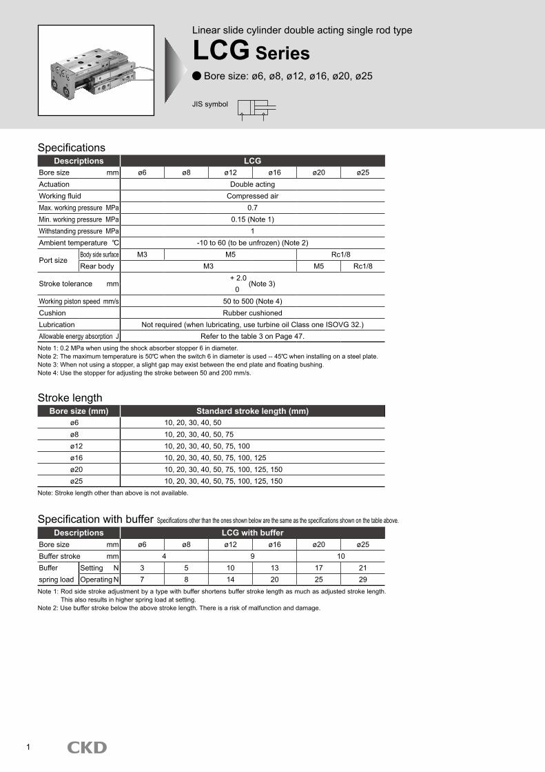
SpecificationsDescriptions LCG
Bore size mm ø6 ø8 ø12 ø16 ø20 ø25Actuation Double actingWorking fluid Compressed airMax. working pressure MPa 0.7Min. working pressure MPa 0.15 (Note 1)Withstanding pressure MPa 1Ambient temperature -10 to 60 (to be unfrozen) (Note 2)
Port sizeBody side surface M3 M5 Rc1/8Rear body M3 M5 Rc1/8
Stroke tolerance mm+ 2.0
(Note 3)0
Working piston speed mm/s 50 to 500 (Note 4)Cushion Rubber cushionedLubrication Not required (when lubricating, use turbine oil Class one ISOVG 32.)Allowable energy absorption J Refer to the table 3 on Page 47.
Stroke length
Note: Stroke length other than above is not available.
Bore size (mm) Standard stroke length (mm)ø6 10, 20, 30, 40, 50ø8 10, 20, 30, 40, 50, 75ø12 10, 20, 30, 40, 50, 75, 100ø16 10, 20, 30, 40, 50, 75, 100, 125ø20 10, 20, 30, 40, 50, 75, 100, 125, 150ø25 10, 20, 30, 40, 50, 75, 100, 125, 150
Note 1: 0.2 MPa when using the shock absorber stopper 6 in diameter.Note 2: The maximum temperature is 50 when the switch 6 in diameter is used -- 45 when installing on a steel plate.Note 3: When not using a stopper, a slight gap may exist between the end plate and floating bushing.Note 4: Use the stopper for adjusting the stroke between 50 and 200 mm/s.
1
JIS symbol
Linear slide cylinder double acting single rod type
LCG Series Bore size: ø6, ø8, ø12, ø16, ø20, ø25
Specification with buffer Specifications other than the ones shown below are the same as the specifications shown on the table above.
Descriptions LCG with bufferBore size mm ø6 ø8 ø12 ø16 ø20 ø25Buffer stroke mm 4 9 10Bufferspring load
Setting N 3 5 10 13 17 21Operating N 7 8 14 20 25 29
Note 1: Rod side stroke adjustment by a type with buffer shortens buffer stroke length as much as adjusted stroke length. This also results in higher spring load at setting.Note 2: Use buffer stroke below the above stroke length. There is a risk of malfunction and damage.
LCG SeriesSpecifications
2
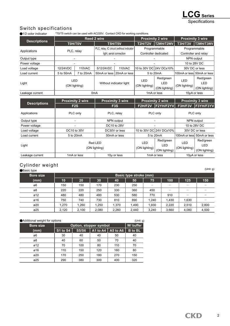
Switch speci f icat ions1/2 color indicator
DescriptionsProximity 2 wire Proximity 3 wire Proximity 2 wire Proximity 3 wire
F2S F3S F2H/F2V F2YH/F2YV F3H/F3V F3YH/F3YV
Applications PLC only PLC, relay PLC only PLC only
Output type - NPN output - NPN outputPower voltage - DC10 to 28V - 10 to 28V DCLoad voltage DC10 to 30V DC30V or less 10 to 30V DC 24V DC 10% 30V DC or lessLoad current 5 to 20mA 50mA or less 5 to 20mA 100mA or less 50mA or less
LightRed LED
(ON lighting)LED
(ON lighting)
Red/greenLED
(ON lighting)
LED (ON lighting)
Red/greenLED
(ON lighting)Leakage current 1mA or less 10μ or less 1mA or less 10 A or less
Cyl inder weightBasic type
Bore size Basic type stroke (mm)(mm) 10 20 30 40 50 75 100 125 150ø6 150 150 170 230 250 - - - -
ø8 220 220 250 330 360 450 - - -
ø12 480 480 480 530 580 770 910 - -
ø16 750 740 730 810 890 1,240 1,430 1,630 -
ø20 1,270 1,260 1,250 1,370 1,490 1,930 2,220 2,510 2,800ø25 2,120 2,100 2,080 2,260 2,440 3,240 3,660 4,080 4,500
Additional weight for optionsBore size Option, stopper symbol W/ buffer
(mm) S1 to S4 S5/S6 A1 to A4 A5 to A6 B to BLø6 30 40 40 50 40ø8 40 60 50 70 40ø12 70 100 80 110 70ø16 110 150 120 160 80ø20 170 250 180 270 150ø25 290 380 300 400 320
(Unit: g)
DescriptionsReed 2 wire Proximity 2 wire Proximity 3 wire
T0H/T0V T5H/T5V T2H/T2V T2WH/T2WV T3H/T3V T3WH/T3WV
Applications PLC, relayPLC, relay, IC circuit (without indicator
light, serial connectionProgrammable
Controller dedicatedProgrammable
Controller and relayOutput type - - - NPN outputPower voltage - - - 10 to 28V DCLoad voltage 12/24VDC 110VAC 5/12/24VDC 110VAC 10 to 30V DC 24V DC 10% 30V DC or lessLoad current 5 to 50mA 7 to 20mA 50mA or less 20mA or less 5 to 20mA 100mA or less 50mA or less
LightLED
(ON lighting)Without indicator light
LED (ON lighting)
Red/greenLED
(ON lighting)
LED (ON lighting)
Red/greenLED
(ON lighting)Leakage current 0mA 1mA or less 10 A or less
*T0/T5 swtich can be used with AC220V. Contact CKD for working conditions.
(Unit: g)
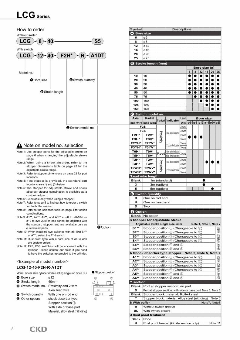
Symbol DescriptionsBore size6 ø68 ø8
12 ø1216 ø1620 ø2025 ø25
Stroke length (mm)Bore size (ø)
6 8 12 16 20 2510 1020 2030 3040 4050 5075 75
100 100125 125150 150
Switch model no.Axial
lead wireRadial
lead wireContact Indicator
Lead wire
Bore sizeø6 ø8 ø12 ø16 ø20 ø25
F2S
Proximity
One color indicator
2-wireF3S 3-wire
F2H* F2V* 2-wireF3H* F3V* 3-wire
F2YH* F2YV*2 color indicator
2-wireF3YH* F3YV* 3-wireT0H* T0V*
ReedOne color indicator
2-wireT5H* T5V* No indicatorT2H* T2V* Proximity
One color indicator2-wire
T3H* T3V* 3-wireT2WH* T2WV*
2 color indicator2-wire
T3WH* T3WV* 3-wire*Lead wire lengthBlank 1m (standard)
3 3m (option)5 5m (option)
Switch quantityR One on rod endH One on head endD Two
OptionBlank No option
S Stopper for adjustable strokeAdjustable stroke single side 5mm Note 1, Note 5, Note 7
S1** Stopper position 1 (Changeable to 4 )
Stoppe
r insta
llation
position
S2** Stopper position 2 (Changeable to 3 )S3** Stopper position 3 (Changeable to 2 )S4** Stopper position 4 (Changeable to 1 )S5** Stopper position 1 and 3
S6** Stopper position 2 and 4
A Shock absorber type stopper Note 2, Note 5, Note 7A1** Stopper position 1 (Changeable to 4 )
Stoppe
r insta
llation
position
A2** Stopper position 2 (Changeable to 3 )A3** Stopper position 3 (Changeable to 2 )A4** Stopper position 4 (Changeable to 1 )A5** Stopper position 1 and 3
A6** Stopper position 2 and 4
** sectionBlank Port at stopper section: no port
D Port at stopper section: with side or base port Note 3, Note 6Blank Stopper block material: Rolled steel
T Stopper block material: Alloy steel (nitriding) Note 6B With buffer Note7, Note8
B Without switch grooveBL With switch groove
U Rust proof treatmentBlank None
U Rust proof treated (Guide section only) Note 11
LCG Series
How to orderWithout switch
With switch
Note on model no. selectionNote 1: Use stopper parts for the adjustable stroke on
page 6 when changing the adjustable stroke range.
Note 2: When using a shock absorber, refer to the stopper dimensions table on page 23 for the adjustable stroke range.
Note 3: Refer to stopper dimensions on page 23 for port locations.
Note 4: If no stopper is provided, the standard port locations are (1) and (3) below.
Note 5: The stopper for adjustable stroke and shock absorber stopper combination is available as a customized part.
Note 6: Selectable only when using a stopper.Note 7: Refer to page 5 to find out how to order a switch
for the buffer section. Note 8: Refer to the selection table on page 4 for option
combinations.Note 9: A1**, A2**, A5**, and A6** at ø6 to ø8-10st or
ø12 to ø25-20st or less cannot be adjusted with the standard stopper, and are available only as customized parts.
Note 10: When installing two switches with ø6-10st S*** or A***, select the F*H switch.
Note 11: Rust proof type with a bore size of ø6 to ø16 are custom orders.
Note 12: F2S, F3S switchesl will be enclosed with the cylinder. Please contact our sales if you need to have the switches assembled to the cylinder.
<Example of model number>LCG-12-40-F2H-R-A1DTModel: Linear slide cylinder double acting single rod type LCGA Bore size : ø12B Stroke length : 40mmC Switch model no. : Proximity and 2 wire Axial lead wireD Switch quantity : With one on rod endE Other options : shock absorber type Stopper position 1
With side or base port Material, alloy steel (nitriding)
LCG S5408
Model no.
Bore sizeA
Stroke lengthB
LCG 4012 F2H* R A1DT
A
B
C
D
E
Switch model no.C
Switch quantityD
E Option
Stopper position
3
1 3
42
LCG SeriesHow to order
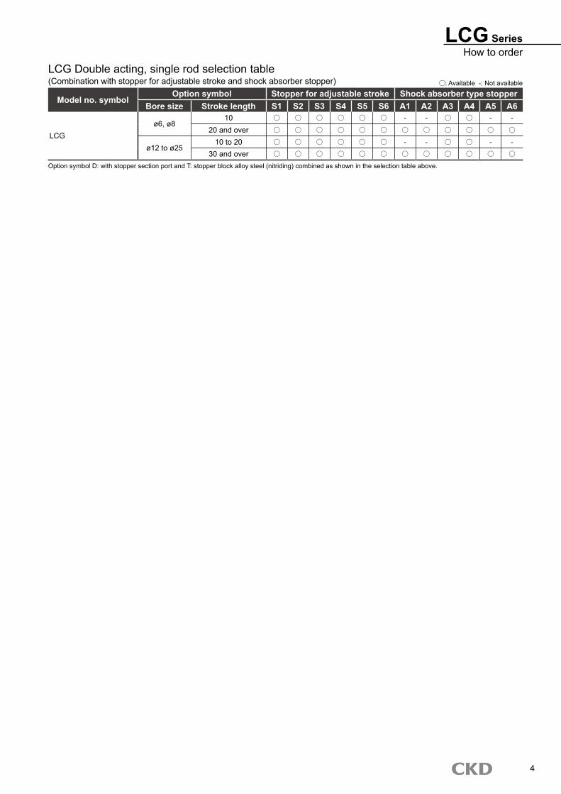
LCG Double acting, single rod selection table(Combination with stopper for adjustable stroke and shock absorber stopper)
Model no. symbolOption symbol Stopper for adjustable stroke Shock absorber type stopper
Bore size Stroke length S1 S2 S3 S4 S5 S6 A1 A2 A3 A4 A5 A6
LCGø6, ø8
10 - - - -
20 and over
ø12 to ø2510 to 20 - - - -
30 and over
: Available -: Not available
Option symbol D: with stopper section port and T: stopper block alloy steel (nitriding) combined as shown in the selection table above.
4
Switch model no.(Page 27 item C )
Switch model no.(Page 27 item C )
LCG Series
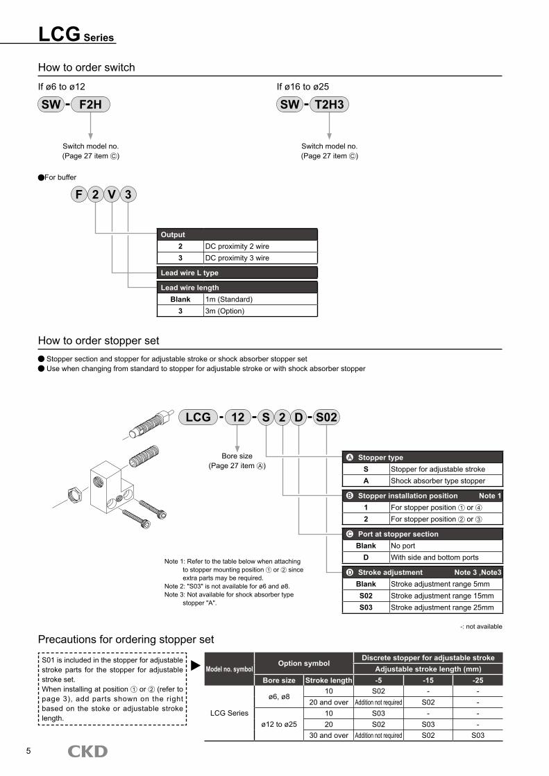
How to order switch
If ø6 to ø12 If ø16 to ø25
How to order stopper set Stopper section and stopper for adjustable stroke or shock absorber stopper set Use when changing from standard to stopper for adjustable stroke or with shock absorber stopper
SW F2H SW T2H3
Precautions for ordering stopper set
S01 is included in the stopper for adjustable stroke parts for the stopper for adjustable stroke set.When installing at position 1 or 2 (refer to page 3), add parts shown on the right based on the stoke or adjustable stroke length.
Model no. symbolOption symbol
Discrete stopper for adjustable strokeAdjustable stroke length (mm)
Bore size Stroke length -5 -15 -25
LCG Series
ø6, ø810 S02 - -
20 and over Addition not required S02 -
ø12 to ø2510 S03 - -20 S02 S03 -
30 and over Addition not required S02 S03
-: not available
5
Stopper typeS Stopper for adjustable strokeA Shock absorber type stopper
Stopper installation position Note 11 For stopper position 1 or 4
2 For stopper position 2 or 3
Port at stopper sectionBlank No port
D With side and bottom ports
Stroke adjustment Note 3 ,Note3Blank Stroke adjustment range 5mmS02 Stroke adjustment range 15mmS03 Stroke adjustment range 25mm
LCG S12 2 D S02
D
Note 1: Refer to the table below when attaching to stopper mounting position 1 or 2 since extra parts may be required.Note 2: "S03" is not available for ø6 and ø8.Note 3: Not available for shock absorber type stopper "A".
For buffer
Output2 DC proximity 2 wire3 DC proximity 3 wire
Lead wire L type
Lead wire lengthBlank 1m (Standard)
3 3m (Option)
2 V 3F
Bore size(Page 27 item A )
A
B
C
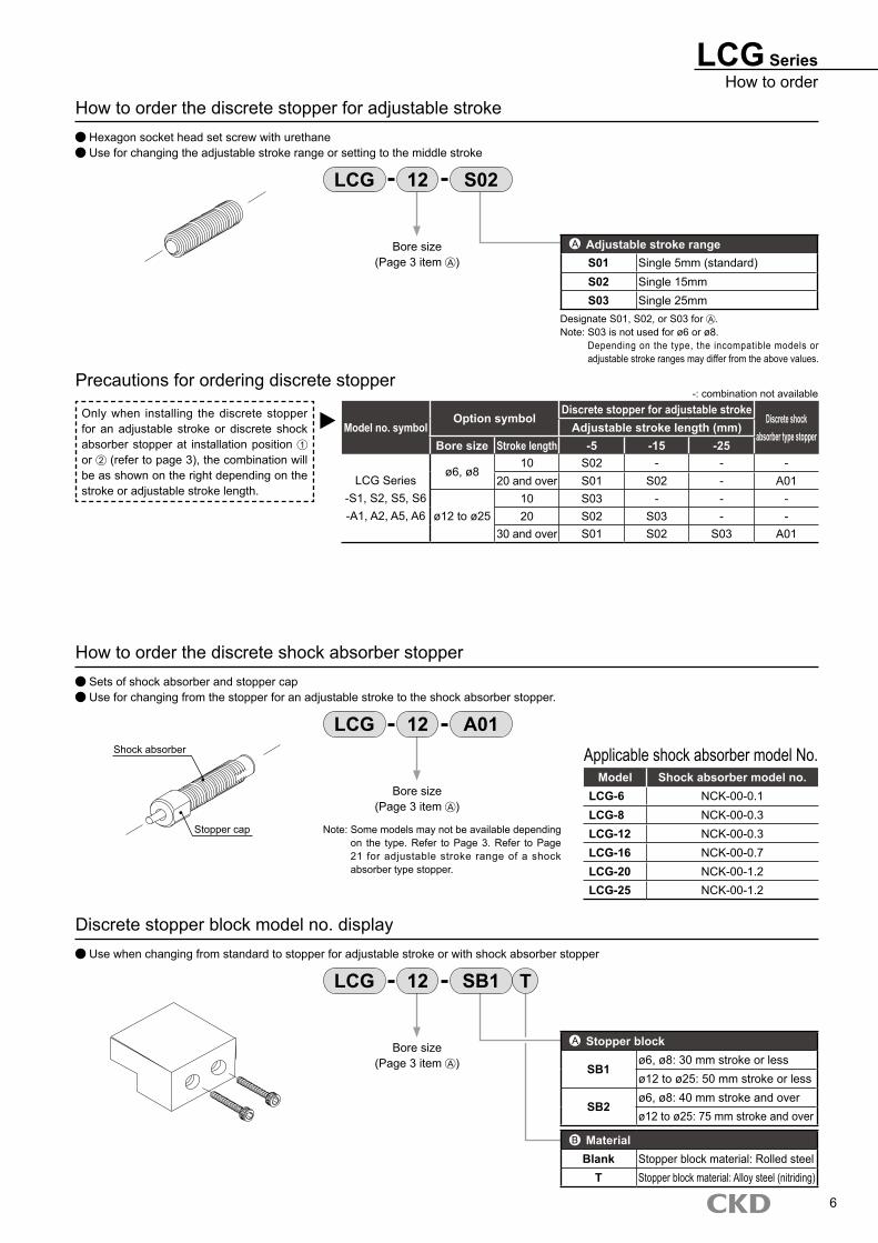
LCG SeriesHow to order
How to order the discrete stopper for adjustable stroke Hexagon socket head set screw with urethane Use for changing the adjustable stroke range or setting to the middle stroke
Adjustable stroke rangeS01 Single 5mm (standard)S02 Single 15mmS03 Single 25mm
ABore size(Page 3 item A )
LCG 12 S02
Precautions for ordering discrete stopper
Only when installing the discrete stopper for an adjustable stroke or discrete shock absorber stopper at installation position 1 or 2 (refer to page 3), the combination will be as shown on the right depending on the stroke or adjustable stroke length.
Model no. symbolOption symbol
Discrete stopper for adjustable strokeDiscrete shock
absorber type stopperAdjustable stroke length (mm)
Bore size Stroke length -5 -15 -25
LCG Series-S1, S2, S5, S6-A1, A2, A5, A6
ø6, ø810 S02 - - -
20 and over S01 S02 - A01
ø12 to ø2510 S03 - - -20 S02 S03 - -
30 and over S01 S02 S03 A01
-: combination not available
How to order the discrete shock absorber stopper Sets of shock absorber and stopper cap Use for changing from the stopper for an adjustable stroke to the shock absorber stopper.
Model Shock absorber model no.LCG-6 NCK-00-0.1LCG-8 NCK-00-0.3LCG-12 NCK-00-0.3LCG-16 NCK-00-0.7LCG-20 NCK-00-1.2LCG-25 NCK-00-1.2
Bore size(Page 3 item A )
LCG 12 A01
Discrete stopper block model no. display Use when changing from standard to stopper for adjustable stroke or with shock absorber stopper
Stopper block
SB1ø6, ø8: 30 mm stroke or lessø12 to ø25: 50 mm stroke or less
SB2ø6, ø8: 40 mm stroke and overø12 to ø25: 75 mm stroke and over
MaterialBlank Stopper block material: Rolled steel
T Stopper block material: Alloy steel (nitriding)
ABore size(Page 3 item A )
LCG 12 SB1
Applicable shock absorber model No.
Note: Some models may not be available depending on the type. Refer to Page 3. Refer to Page 21 for adjustable stroke range of a shock absorber type stopper.
T
B
Designate S01, S02, or S03 for A .Note: S03 is not used for ø6 or ø8.
Depending on the type, the incompatible models or adjustable stroke ranges may differ from the above values.
6
Shock absorber
Stopper cap
LCG Series
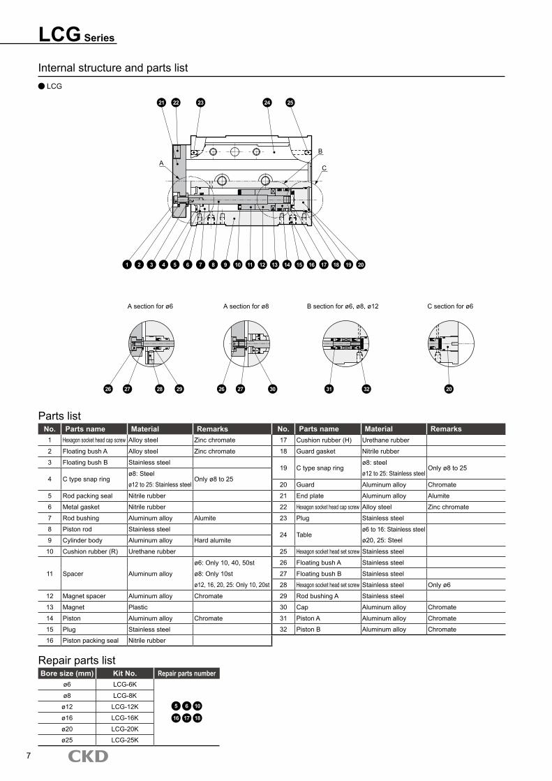
Internal structure and parts list LCG
No. Parts name Material Remarks No. Parts name Material Remarks1 Hexagon socket head cap screw Alloy steel Zinc chromate 17 Cushion rubber (H) Urethane rubber
2 Floating bush A Alloy steel Zinc chromate 18 Guard gasket Nitrile rubber
3 Floating bush B Stainless steel19 C type snap ring
ø8: steelOnly ø8 to 25
4 C type snap ringø8: Steel
Only ø8 to 25ø12 to 25: Stainless steel
ø12 to 25: Stainless steel 20 Guard Aluminum alloy Chromate
5 Rod packing seal Nitrile rubber 21 End plate Aluminum alloy Alumite
6 Metal gasket Nitrile rubber 22 Hexagon socket head cap screw Alloy steel Zinc chromate
7 Rod bushing Aluminum alloy Alumite 23 Plug Stainless steel
8 Piston rod Stainless steel24 Table
ø6 to 16: Stainless steel
9 Cylinder body Aluminum alloy Hard alumite ø20, 25: Steel
10 Cushion rubber (R) Urethane rubber 25 Hexagon socket head set screw Stainless steel
11 Spacer Aluminum alloy
ø6: Only 10, 40, 50st 26 Floating bush A Stainless steel
ø8: Only 10st 27 Floating bush B Stainless steel
ø12, 16, 20, 25: Only 10, 20st 28 Hexagon socket head set screw Stainless steel Only ø6
12 Magnet spacer Aluminum alloy Chromate 29 Rod bushing A Stainless steel
13 Magnet Plastic 30 Cap Aluminum alloy Chromate
14 Piston Aluminum alloy Chromate 31 Piston A Aluminum alloy Chromate
15 Plug Stainless steel 32 Piston B Aluminum alloy Chromate
16 Piston packing seal Nitrile rubber
Parts list
Bore size (mm) Kit No. Repair parts numberø6 LCG-6K
5 6 10
16 17 18
ø8 LCG-8K
ø12 LCG-12K
ø16 LCG-16K
ø20 LCG-20K
ø25 LCG-25K
Repair parts list
7
21 22 23 24 25
1 2 3 4 5 6 7 8 9 10 11 12 13 14 15 16 17 18 19 20
A
B
C
A section for ø6 A section for ø8 B section for ø6, ø8, ø12 C section for ø6
26 27 28 29 26 27 30 31 32 20
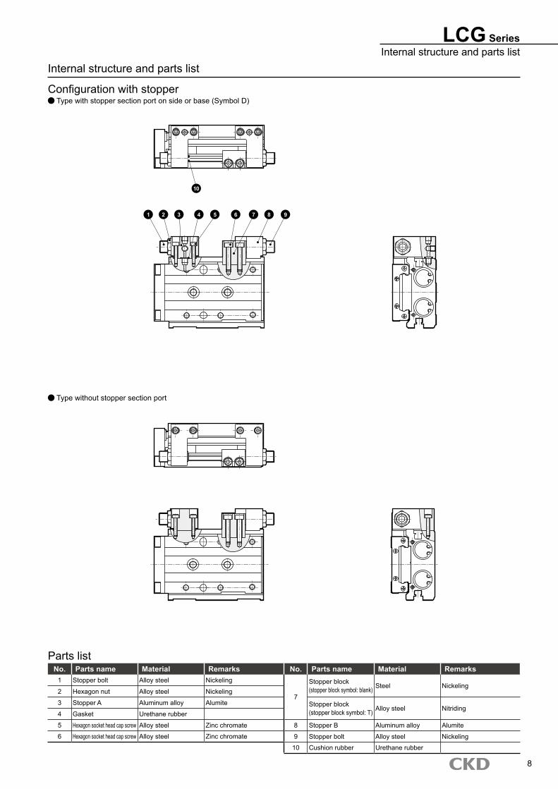
LCG SeriesInternal structure and parts list
Internal structure and parts list
Configuration with stopper Type with stopper section port on side or base (Symbol D)
Type without stopper section port
No. Parts name Material Remarks No. Parts name Material Remarks1 Stopper bolt Alloy steel Nickeling
7
Stopper block(stopper block symbol: blank) Steel Nickeling
2 Hexagon nut Alloy steel Nickeling
3 Stopper A Aluminum alloy Alumite Stopper block(stopper block symbol: T) Alloy steel Nitriding
4 Gasket Urethane rubber
5 Hexagon socket head cap screw Alloy steel Zinc chromate 8 Stopper B Aluminum alloy Alumite
6 Hexagon socket head cap screw Alloy steel Zinc chromate 9 Stopper bolt Alloy steel Nickeling
10 Cushion rubber Urethane rubber
Parts list
8
1 2 3 4 5 6 7 8 9
10
�
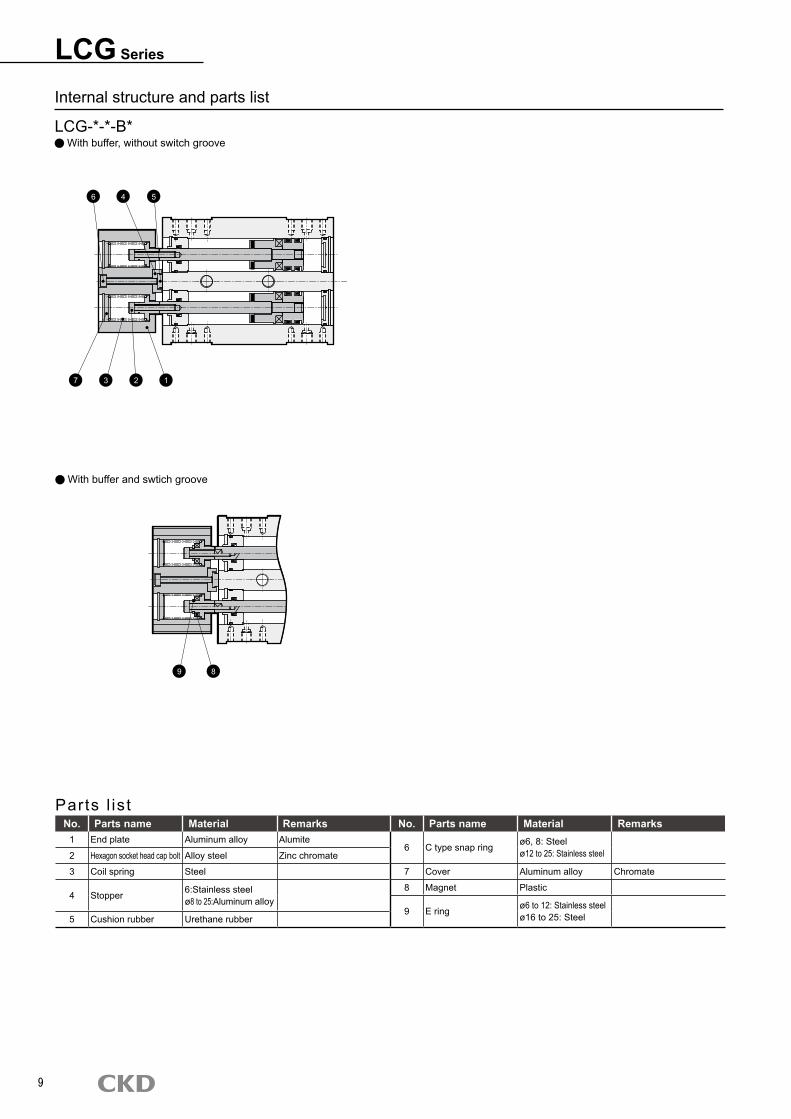
LCG Series
Internal structure and parts list
LCG-*-*-B* With buffer, without switch groove
With buffer and swtich groove
Parts l is tNo. Parts name Material Remarks No. Parts name Material Remarks
1 End plate Aluminum alloy Alumite6 C type snap ring ø6, 8: Steel
ø12 to 25: Stainless steel2 Hexagon socket head cap bolt Alloy steel Zinc chromate
3 Coil spring Steel 7 Cover Aluminum alloy Chromate
4 Stopper 6:Stainless steelø8 to 25:Aluminum alloy
8 Magnet Plastic
9 E ring ø6 to 12: Stainless steel ø16 to 25: Steel5 Cushion rubber Urethane rubber
1237
6 4 5
89

10
M E M OM E M O
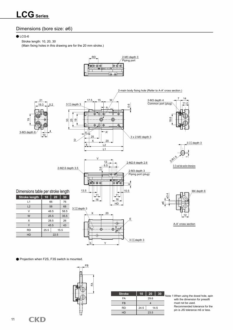
LCG Series
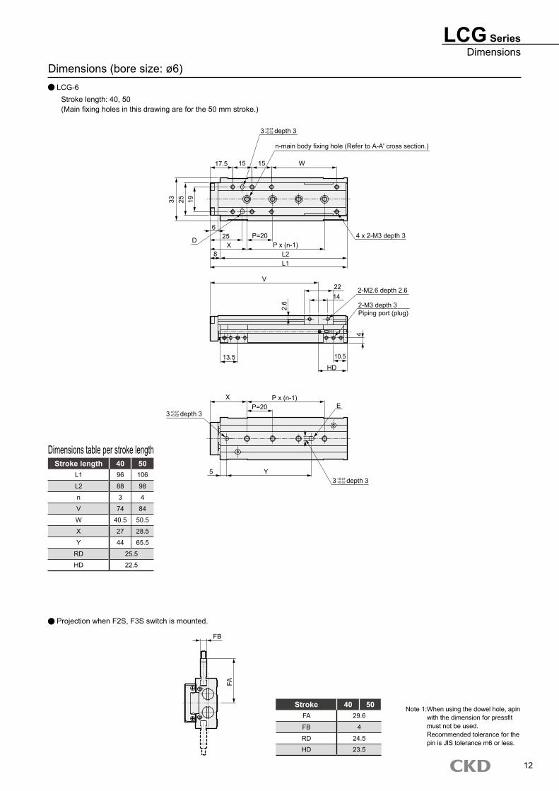
Dimensions (bore size: ø6) LCG-6
Stroke length: 10, 20, 30(Main fixing holes in this drawing are for the 20 mm stroke.)
Stroke length 10 20 30L1 66 76
L2 58 68
V 48.5 58.5
W 25.5 35.5
X 28.5 26
Y 45.5 43
RD 25.5 15.5
HD 22.5
Dimensions table per stroke length
11
Projection when F2S, F3S switch is mounted.
Stroke 10 20 30FA 29.6
FB 4
RD 24.5 14.5
HD 23.5
Note 1: When using the dowel hole, apin with the dimension for pressfit must not be used. Recommended tolerance for the pin is JIS tolerance m6 or less.
FB
FA
RD 2-M3 depth 3Piping port
21
3-M3 depth 6
19.3 0.2
19
410
3 depth 3+0.07+0.02
33 25 19
D
6
8
25X
A'
20L2L1
A 1
17.5 15 W
0.6
2-main body fixing hole (Refer to A-A' cross section.)
3 x 2-M3 depth 3
2-M3 depth 4Common port (plug)
7 14
11.2
18.6
2-M2.6 depth 3.5
V136.5
2.6
2-M2.6 depth 2.6
2-M3 depth 3Piping port (plug)
13.511
16
1116
HD
10.5
4
3 depth 3
X 20
5 Y3 depth 3
E
3 depth 3
2-R1.5
D, E oval hole section dimensions
1M4 depth 6
ø3.4
ø6
12
A-A' cross section
+0.07+0.02
+0.07+0.02
+0.07+0.02
LCG SeriesDimensions
Dimensions (bore size: ø6) LCG-6
Stroke length: 40, 50(Main fixing holes in this drawing are for the 50 mm stroke.)
Stroke length 40 50L1 96 106
L2 88 98
n 3 4
V 74 84
W 40.5 50.5
X 27 28.5
Y 44 65.5
RD 25.5
HD 22.5
Dimensions table per stroke length
12
Projection when F2S, F3S switch is mounted.
Stroke 40 50FA 29.6
FB 4
RD 24.5
HD 23.5
FB
FA
Note 1: When using the dowel hole, apin with the dimension for pressfit must not be used. Recommended tolerance for the pin is JIS tolerance m6 or less.
3 depth 3
n-main body fixing hole (Refer to A-A' cross section.)
17.5 15 15 W33 25 19
D
625
X8
P=20P x (n-1)
L2L1
4 x 2-M3 depth 3
V2214
2-M2.6 depth 2.62.
6 2-M3 depth 3Piping port (plug)
13.5 10.5
HD4
X P x (n-1)EP=20
3 depth 3
5 Y3 depth 3
+0.07+0.02
+0.07+0.02
+0.07+0.02
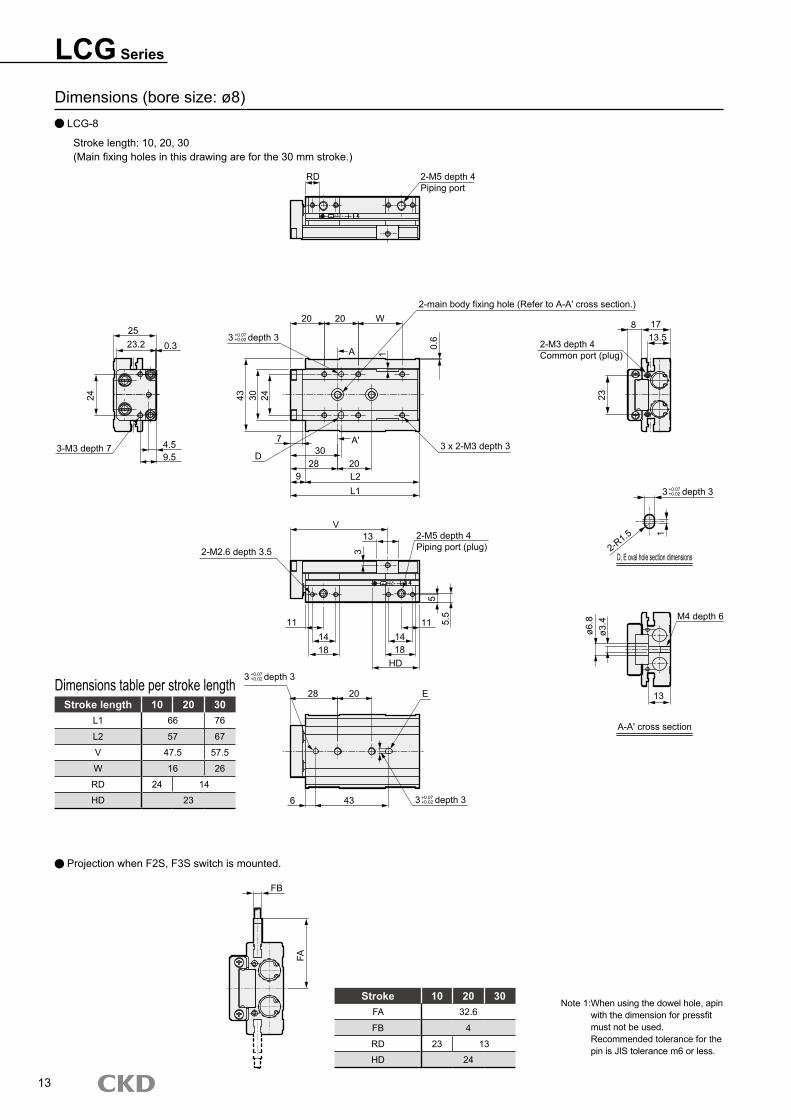
LCG Series
Dimensions (bore size: ø8) LCG-8
Stroke length: 10, 20, 30(Main fixing holes in this drawing are for the 30 mm stroke.)
Stroke length 10 20 30L1 66 76
L2 57 67
V 47.5 57.5
W 16 26
RD 24 14
HD 23
Dimensions table per stroke length
13
Projection when F2S, F3S switch is mounted.
Stroke 10 20 30FA 32.6
FB 4
RD 23 13
HD 24
FB
FA
Note 1: When using the dowel hole, apin with the dimension for pressfit must not be used. Recommended tolerance for the pin is JIS tolerance m6 or less.
RD 2-M5 depth 4Piping port
2523.2 0.3
24
9.53-M3 depth 7 4.5
3 depth 3
20 20 W2-main body fixing hole (Refer to A-A' cross section.)
A 1
0.6
3 x 2-M3 depth 3A' 730
28 20D
9 L2L1
43 30 24
2-M3 depth 4Common port (plug)
23
8 1713.5
3 depth 3
2-R1.5
D, E oval hole section dimensions
1
M4 depth 6
ø6.8
ø3.4
13
A-A' cross section
V13
3
2-M5 depth 4Piping port (plug)
55.
5
111418
HD
111418
2-M2.6 depth 3.5
3 depth 3
28 20 E
3 depth 3436
+0.07+0.02
+0.07+0.02
+0.07+0.02
+0.07+0.02
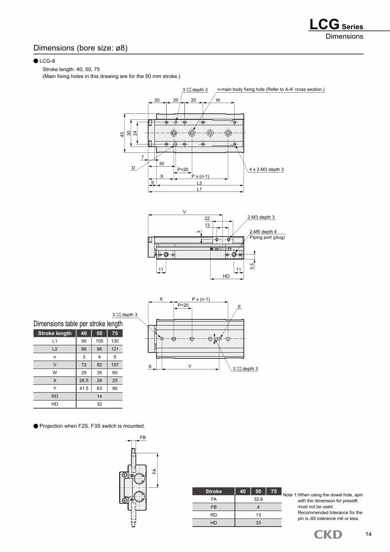
LCG SeriesDimensions
Dimensions (bore size: ø8) LCG-8
Stroke length: 40, 50, 75(Main fixing holes in this drawing are for the 50 mm stroke.)
Stroke length 40 50 75L1 95 105 130
L2 86 96 121
n 3 4 5
V 72 82 107
W 25 35 60
X 26.5 28 25
Y 41.5 63 80
RD 14
HD 32
Dimensions table per stroke length
14
Projection when F2S, F3S switch is mounted.
Stroke 40 50 75FA 32.6
FB 4
RD 13
HD 33
FB
FA
Note 1: When using the dowel hole, apin with the dimension for pressfit must not be used. Recommended tolerance for the pin is JIS tolerance m6 or less.
3 depth 3 n-main body fixing hole (Refer to A-A' cross section.)
20 20 20 W
43 30 24
7
D30
XP=20
9 L2L1
P x (n-1)4 x 2-M3 depth 3
V2213
3
2-M3 depth 3
2-M5 depth 4Piping port (plug)
5.5
11HD
11
X P x (n-1)P=20 E
3 depth 3
3 depth 36 Y
+0.07+0.02
+0.07+0.02
+0.07+0.02
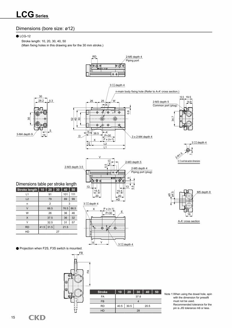
LCG Series
Dimensions (bore size: ø12) LCG-12
Stroke length: 10, 20, 30, 40, 50(Main fixing holes in this drawing are for the 30 mm stroke.)
Stroke length 10 20 30 40 50L1 91 101 111
L2 79 89 99
n 2 3
V 66.5 76.5 86.5
W 26 36 46
X 37.5 36 32
Y 32.5 31 57
RD 41.5 31.5 21.5
HD 27
Dimensions table per stroke length
15
Projection when F2S, F3S switch is mounted.
Stroke 10 20 30 40 50FA 37.8
FB 4
RD 40.5 30.5 20.5
HD 28
FB
FA
Note 1: When using the dowel hole, apin with the dimension for pressfit must not be used. Recommended tolerance for the pin is JIS tolerance m6 or less.
3 depth 4
RD 2-M5 depth 4Piping port
n-main body fixing hole (Refer to A-A' cross section.)
26 25 WA
52 40 30
0.8
9
1
D38.5 A'
X12
P=30P x (n-1)
L2L1
3 x 2-M4 depth 4
V178
5.5
2-M3 depth 5
2-M5 depth 4Piping port (plug)
2-M3 depth 3.5
55.
5131315.5 15.5
20 20HD
3 depth 4
X P x (n-1)P=30 E
8 Y3 depth 4
3028.2 0.3
30
5143-M4 depth 9
2-M3 depth 5Common port (plug)
34.7
10.5 19.5
14.8
3 depth 4
D, E oval hole section dimensions2-R1.5 1
M5 depth 8
ø9 ø4.5
16
A-A' cross section
+0.07+0.02
+0.07+0.02
+0.07+0.02
+0.07+0.02
LCG SeriesDimensions
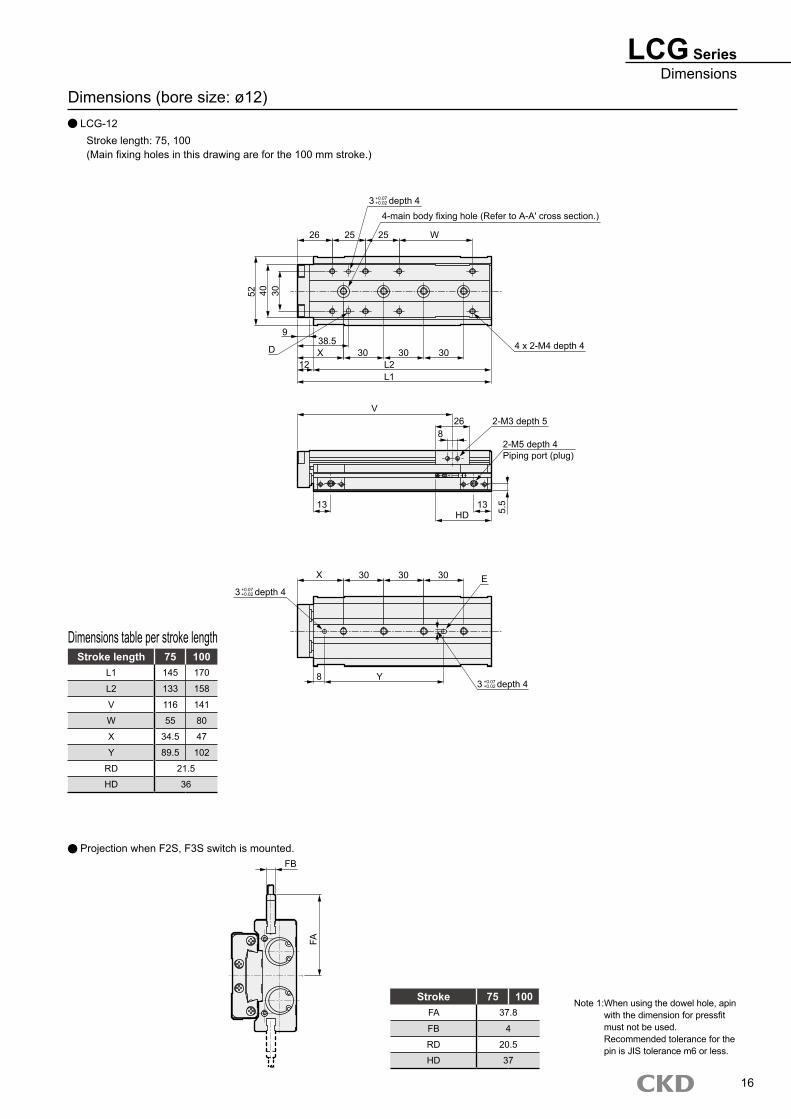
Dimensions (bore size: ø12) LCG-12
Stroke length: 75, 100(Main fixing holes in this drawing are for the 100 mm stroke.)
Stroke length 75 100L1 145 170
L2 133 158
V 116 141
W 55 80
X 34.5 47
Y 89.5 102
RD 21.5
HD 36
Dimensions table per stroke length
16
Stroke 75 100FA 37.8
FB 4
RD 20.5
HD 37
Projection when F2S, F3S switch is mounted.FB
FA
Note 1: When using the dowel hole, apin with the dimension for pressfit must not be used. Recommended tolerance for the pin is JIS tolerance m6 or less.
3 depth 44-main body fixing hole (Refer to A-A' cross section.)
26 25 25 W52 40 30
9
D12
38.5X 30 30 30
L2L1
4 x 2-M4 depth 4
V26
82-M3 depth 5
2-M5 depth 4Piping port (plug)
13 13HD 5.
5
3 depth 4
X 30 30 30 E
3 depth 4Y8
+0.07+0.02
+0.07+0.02
+0.07+0.02
LCG Series
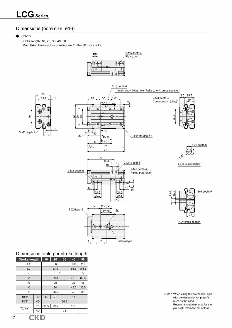
Dimensions (bore size: ø16) LCG-16
Stroke length: 10, 20, 30, 40, 50(Main fixing holes in this drawing are for the 30 mm stroke.)
Stroke length 10 20 30 40 50L1 96 106 116
L2 83.5 93.5 103.5
n 2 3
V 69.8 79.8 89.8
W 28 38 48
X 34 45.5 35.5
Y 28.5 40 60
T0/5* RD 37 27 17
T2/3* HD 36.5
T2/3W*RD 39.5 29.5 19.5
HD 34
Dimensions table per stroke length
17
Note 1: When using the dowel hole, apin with the dimension for pressfit must not be used. Recommended tolerance for the pin is JIS tolerance m6 or less.
6 depth 6
RD 2-M5 depth 4Piping port
n-main body fixing hole (Refer to A-A' cross section.)
28 30 W
A 1 1
62 50 40
D9
43A'
P=30P x (n-1)X
12.5 L2L1
3 x 2-M5 depth 5
V20.5
102-M4 depth 6
2-M3 depth 5 2-M5 depth 4Piping port (plug)
66.
5131415.520.2
15.520.2
HD
6 depth 6
6 depth 6
P x (n-1)XP=30 E
8 Y
2-M3 depth 4Common port (plug)
12.5 25.519.7
39.4
6 depth 6
D, E oval hole section dimensions
2-R3 1
M6 depth 9
ø9.8
ø5.5
21
A-A' cross section
3835.2 0.3
5.518
40
3-M5 depth 9
+0.07+0.02
+0.07+0.02
+0.07+0.02
+0.07+0.02
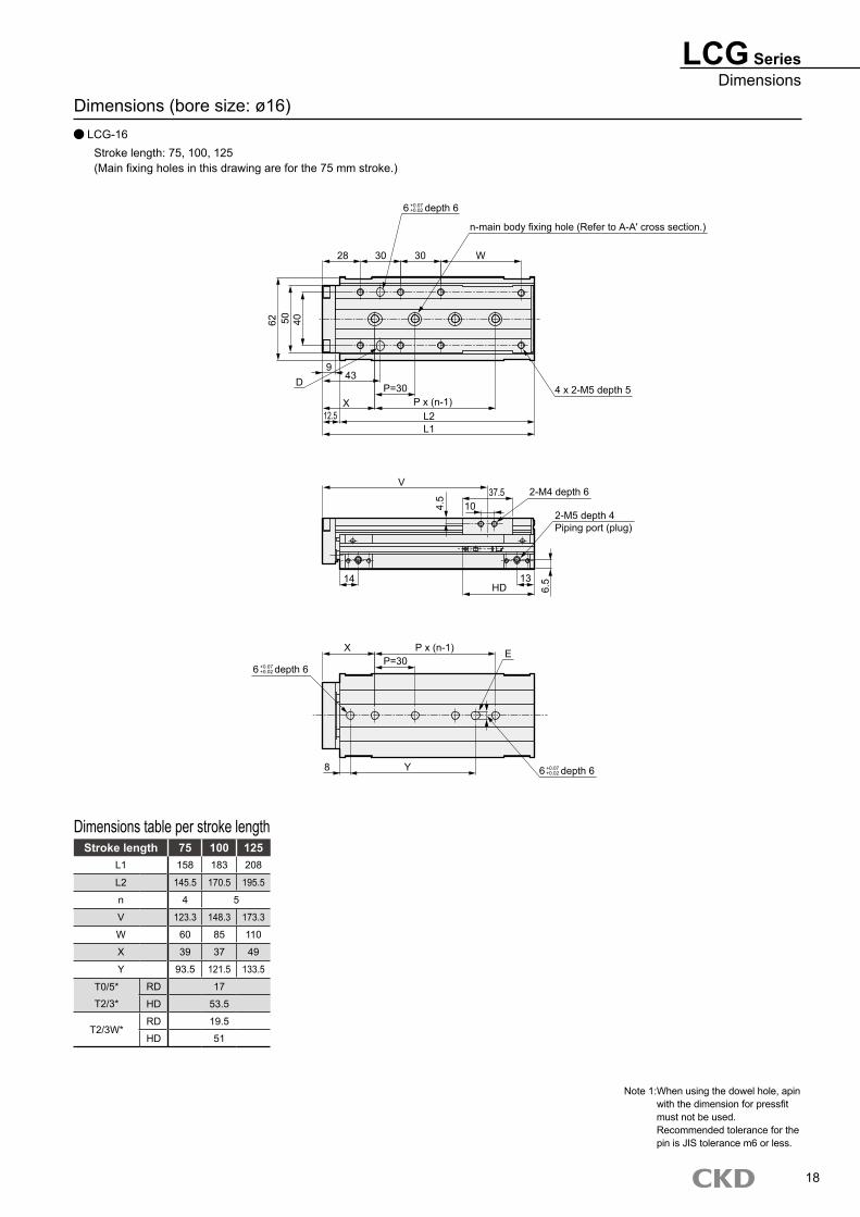
Dimensions (bore size: ø16) LCG-16
Stroke length: 75, 100, 125(Main fixing holes in this drawing are for the 75 mm stroke.)
Stroke length 75 100 125L1 158 183 208
L2 145.5 170.5 195.5
n 4 5
V 123.3 148.3 173.3
W 60 85 110
X 39 37 49
Y 93.5 121.5 133.5
T0/5* RD 17
T2/3* HD 53.5
T2/3W*RD 19.5
HD 51
Dimensions table per stroke length
LCG SeriesDimensions
18
Note 1: When using the dowel hole, apin with the dimension for pressfit must not be used. Recommended tolerance for the pin is JIS tolerance m6 or less.
6 depth 6
n-main body fixing hole (Refer to A-A' cross section.)
28 30 30 W62 50 40
D9
43
X12.5
P=30P x (n-1)
L2L1
4 x 2-M5 depth 5
V37.5
102-M4 depth 6
2-M5 depth 4Piping port (plug)
4.5
6.513
HD14
X
6 depth 6
P x (n-1)P=30
E
8 Y 6 depth 6
+0.07+0.02
+0.07+0.02
+0.07+0.02
LCG Series
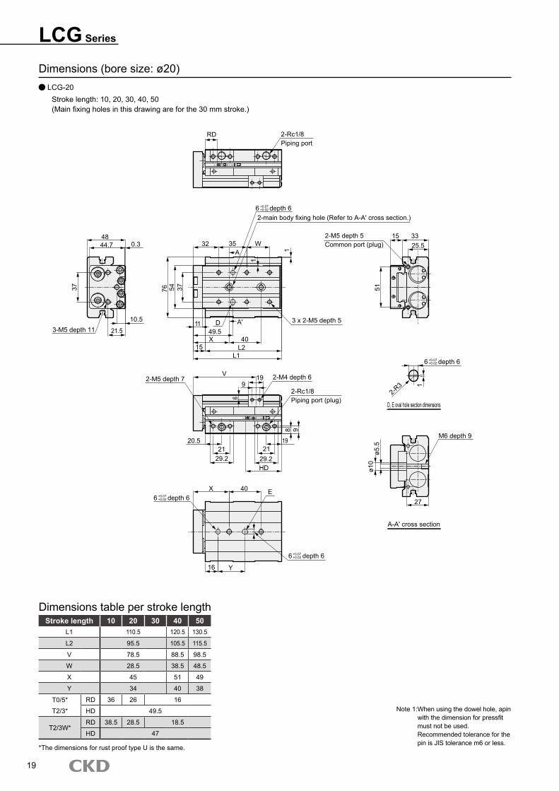
Dimensions (bore size: ø20) LCG-20
Stroke length: 10, 20, 30, 40, 50(Main fixing holes in this drawing are for the 30 mm stroke.)
Stroke length 10 20 30 40 50L1 110.5 120.5 130.5
L2 95.5 105.5 115.5
V 78.5 88.5 98.5
W 28.5 38.5 48.5
X 45 51 49
Y 34 40 38
T0/5* RD 36 26 16
T2/3* HD 49.5
T2/3W*RD 38.5 28.5 18.5
HD 47
Dimensions table per stroke length
19
Note 1: When using the dowel hole, apin with the dimension for pressfit must not be used. Recommended tolerance for the pin is JIS tolerance m6 or less.
*The dimensions for rust proof type U is the same.
2-Rc1/8Piping port (plug)
RD 2-Rc1/8Piping port
6 depth 62-main body fixing hole (Refer to A-A' cross section.)
32 35 WA 1
1
76 54 37
3 x 2-M5 depth 511 D A' 49.5
40X15 L2
L1
4844.7 0.3
10.5
21.53-M5 depth 11
37
2-M5 depth 5Common port (plug)
15 3325.5
51
6 depth 6
2-R3 1
D, E oval hole section dimensions
M6 depth 9
27
A-A' cross section
ø5.5
ø10
2-M4 depth 6V 199
2-M5 depth 7
20.5
6
21 2129.2 29.2
HD
19
8 9
6 depth 6
6 depth 6
X 40 E
Y16
+0.07+0.02
+0.07+0.02
+0.07+0.02
+0.07+0.02
LCG SeriesDimensions
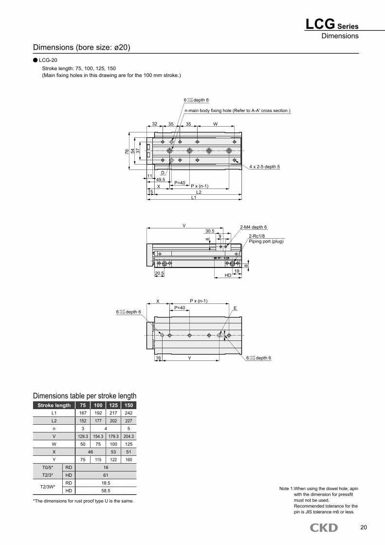
Dimensions (bore size: ø20) LCG-20
Stroke length: 75, 100, 125, 150(Main fixing holes in this drawing are for the 100 mm stroke.)
Stroke length 75 100 125 150L1 167 192 217 242
L2 152 177 202 227
n 3 4 5
V 129.3 154.3 179.3 204.3
W 50 75 100 125
X 46 53 51
Y 75 115 122 160
T0/5* RD 16
T2/3* HD 61
T2/3W*RD 18.5
HD 58.5
Dimensions table per stroke length
20
Note 1: When using the dowel hole, apin with the dimension for pressfit must not be used. Recommended tolerance for the pin is JIS tolerance m6 or less.
*The dimensions for rust proof type U is the same.
6 depth 6
n-main body fixing hole (Refer to A-A' cross section.)
32 35 35 W
4 x 2-5 depth 5
76 54 37
11D
49.5P=40
X15
P x (n-1)L2
L1
V30.5
9
2-M4 depth 6
6 2-Rc1/8Piping port (plug)
8
19HD20.5
P x (n-1)XP=40 E
6 depth 6
6 depth 616 Y
+0.07+0.02
+0.07+0.02
+0.07+0.02
LCG Series
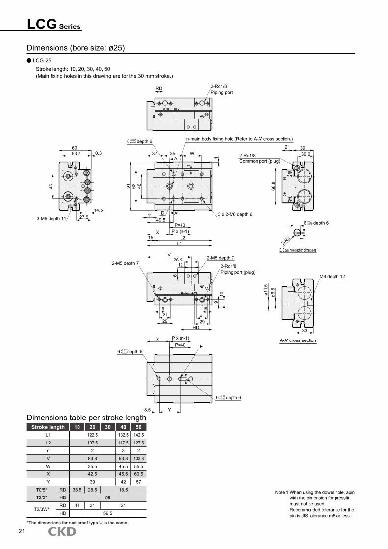
Dimensions (bore size: ø25) LCG-25
Stroke length: 10, 20, 30, 40, 50(Main fixing holes in this drawing are for the 30 mm stroke.)
Stroke length 10 20 30 40 50L1 122.5 132.5 142.5
L2 107.5 117.5 127.5
n 2 3 2
V 83.8 93.8 103.8
W 35.5 45.5 55.5
X 42.5 45.5 60.5
Y 39 42 57
T0/5* RD 38.5 28.5 18.5
T2/3* HD 59
T2/3W*RD 41 31 21
HD 56.5
Dimensions table per stroke length
21*The dimensions for rust proof type U is the same.
Note 1: When using the dowel hole, apin with the dimension for pressfit must not be used. Recommended tolerance for the pin is JIS tolerance m6 or less.
6 depth 6
RD 2-Rc1/8Piping port
6 depth 6 n-main body fixing hole (Refer to A-A' cross section.)
32 35 WA 1
1
91 62 46
3 x 2-M6 depth 611 D A' 49.5
P=40P x (n-1)X
15 L2L1
2-Rc1/8Common port (plug)
21 3930.6
68.8
6 depth 6
D, E oval hole section dimensions2-R
3 1
M8 depth 12
A-A' cross section
33
ø11.
5ø6
.8
2-M5 depth 7
2-Rc1/8Piping port (plug)
V26.5
122-M5 depth 7
1921
6
29
192129
HD
910
X P x (n-1)
EP=40
6 depth 6
8.5 Y
6053.7 0.3
14.527.5
46
3-M6 depth 11
+0.07+0.02
+0.07+0.02
+0.07+0.02
+0.07+0.02
LCG SeriesDimensions
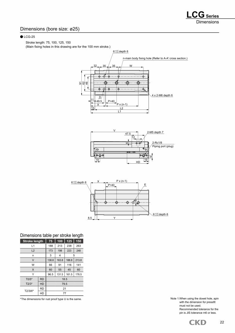
Dimensions (bore size: ø25) LCG-25
Stroke length: 75, 100, 125, 150(Main fixing holes in this drawing are for the 100 mm stroke.)
Stroke length 75 100 125 150L1 188 213 238 263
L2 173 198 223 248
n 3 4 5
V 138.8 163.8 188.8 213.8
W 66 91 116 141
X 60 55 45 60
Y 96.5 131.5 161.5 176.5
T0/5* RD 18.5
T2/3* HD 79.5
T2/3W*RD 21
HD 77
Dimensions table per stroke length
22
Note 1: When using the dowel hole, apin with the dimension for pressfit must not be used. Recommended tolerance for the pin is JIS tolerance m6 or less.
*The dimensions for rust proof type U is the same.
6 depth 6
n-main body fixing hole (Refer to A-A' cross section.)
32 35 35 W
4 x 2-M6 depth 6
91 62 46
D11 49.5 P=40
X P x (n-1)15 L2
L1
V47.5
12
2-M5 depth 7
6
19 19HD
9
2-Rc1/8Piping port (plug)
6 depth 6 X P x (n-1)P=40 E
6 depth 6Y8.5
+0.07+0.02
+0.07+0.02
+0.07+0.02
LCG Series
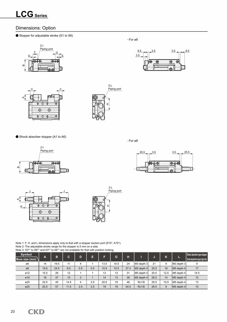
Dimensions: Option Stopper for adjustable stroke (S1 to S6)
Shock absorber stopper (A1 to A6)
SymbolA B C D E F G H I J K L
Shock absorber type stopperStroke adjustment range (single side)Bore size (mm)
ø6 14 19.5 11 4 1 13.5 10.5 24 M3 depth 3 21 9 M3 depth 3 9
ø8 15.6 24.5 9.5 0.5 0.5 10.5 10.5 27.3 M5 depth 4 25.5 16 M5 depth 4 17
ø12 15.5 29 12 1 1 13 13 31 M5 depth 4 25.5 12.5 M5 depth 4 14.5
ø16 18 37 10 2 1 14 13 39 M5 depth 4 28.5 14 M5 depth 4 15
ø20 20.5 45 14.5 4 2.5 20.5 19 46 Rc1/8 29.5 10.5 M5 depth 4 13
ø25 20.5 57 11.5 2.5 2.5 19 19 54.5 Rc1/8 26.5 9 M5 depth 4 10
Note 1: F, H, and L dimensions apply only to that with a stopper section port (S*D*, A*D*).Note 2: The adjustable stroke range for the stopper is 5 mm on a side.Note 3: S3** to S6** and A3** to A6** are not available for that with position locking.
For ø8
For ø8
23
DF G
E
B
2-IPiping port
C C
A
2-LPiping port
H
9.5 3.5
3.5
3.5 9.5
J
B
2-IPiping port
J
K
A
2-LPiping port
H
25.5 3.5 3.5 25.5
24
LCG SeriesOption dimensions
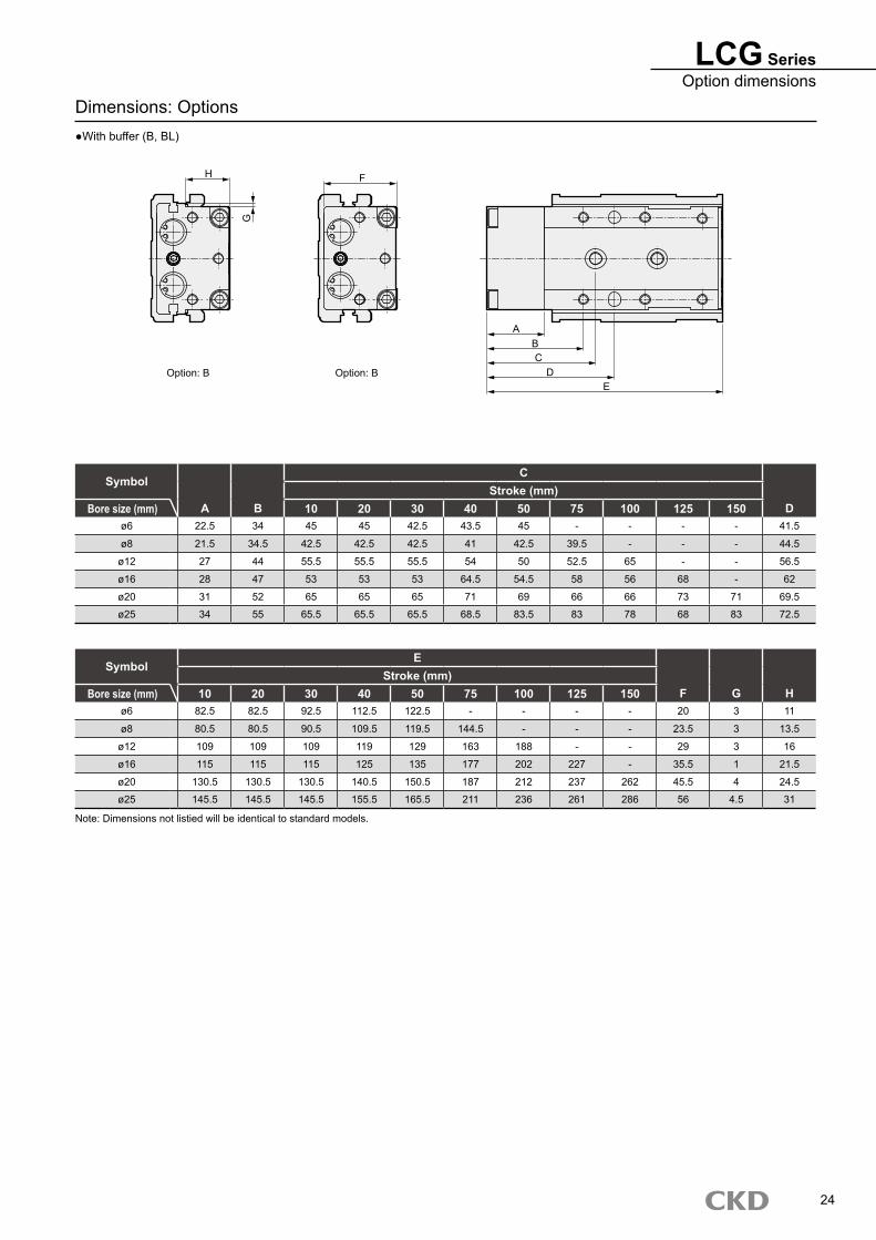
Dimensions: Options●With buffer (B, BL)
SymbolC
Stroke (mm)Bore size (mm) A B 10 20 30 40 50 75 100 125 150 D
ø6 22.5 34 45 45 42.5 43.5 45 - - - - 41.5
ø8 21.5 34.5 42.5 42.5 42.5 41 42.5 39.5 - - - 44.5
ø12 27 44 55.5 55.5 55.5 54 50 52.5 65 - - 56.5
ø16 28 47 53 53 53 64.5 54.5 58 56 68 - 62
ø20 31 52 65 65 65 71 69 66 66 73 71 69.5
ø25 34 55 65.5 65.5 65.5 68.5 83.5 83 78 68 83 72.5
SymbolE
Stroke (mm)Bore size (mm) 10 20 30 40 50 75 100 125 150 F G H
ø6 82.5 82.5 92.5 112.5 122.5 - - - - 20 3 11
ø8 80.5 80.5 90.5 109.5 119.5 144.5 - - - 23.5 3 13.5
ø12 109 109 109 119 129 163 188 - - 29 3 16
ø16 115 115 115 125 135 177 202 227 - 35.5 1 21.5
ø20 130.5 130.5 130.5 140.5 150.5 187 212 237 262 45.5 4 24.5
ø25 145.5 145.5 145.5 155.5 165.5 211 236 261 286 56 4.5 31
Note: Dimensions not listied will be identical to standard models.
ABC
DE
G
H F
Option: BOption: B
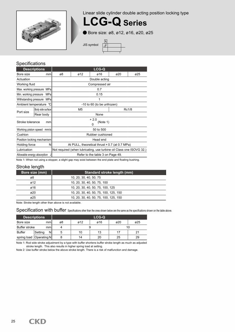
Linear slide cylinder double acting position locking type
LCG-Q SeriesBore size: ø8, ø12, ø16, ø20, ø25
Descriptions LCG-QBore size mm ø8 ø12 ø16 ø20 ø25Actuation Double actingWorking fluid Compressed airMax. working pressure MPa 0.7Min. working pressure MPa 0.15Withstanding pressure MPa 1Ambient temperature -10 to 60 (to be unfrozen)
Port sizeBody side surface M5 Rc1/8Rear body None
Stroke tolerance mm+ 2.0
(Note 1)0
Working piston speed mm/s 50 to 500Cushion Rubber cushionedPosition locking mechanism Head endHolding force N At PULL, theoretical thrust 0.7 (at 0.7 MPa)Lubrication Not required (when lubricating, use turbine oil Class one ISOVG 32.)Allowable energy absorption J Refer to the table 3 on Page 49.
Stroke length
Note: Stroke length other than above is not available.
Bore size (mm) Standard stroke length (mm)ø8 10, 20, 30, 40, 50, 75ø12 10, 20, 30, 40, 50, 75, 100ø16 10, 20, 30, 40, 50, 75, 100, 125ø20 10, 20, 30, 40, 50, 75, 100, 125, 150ø25 10, 20, 30, 40, 50, 75, 100, 125, 150
Note 1: When not using a stopper, a slight gap may exist between the end plate and floating bushing.
Specifications
JIS symbol
25
Linear slide cylinder double acting position locking type
LCG-Q Series Bore size: ø8, ø12, ø16, ø20, ø25
Descriptions LCG-QBore size mm ø8 ø12 ø16 ø20 ø25Buffer stroke mm 4 9 10Bufferspring load
Setting N 5 10 13 17 21Operating N 8 14 20 25 29
Note 1: Rod side stroke adjustment by a type with buffer shortens buffer stroke length as much as adjusted stroke length. This also results in higher spring load at setting.Note 2: Use buffer stroke below the above stroke length. There is a risk of malfunction and damage.
Specification with buffer Specifications other than the ones shown below are the same as the specifications shown on the table above.
LCG-Q SeriesSpecifications
26
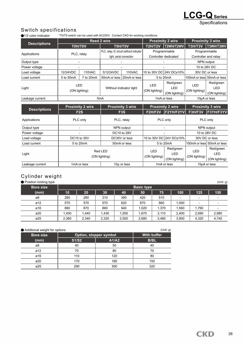
Cyl inder weight Position locking type (Unit: g)
Additional weight for options
Bore size Basic type(mm) 10 20 30 40 50 75 100 125 150ø8 280 280 310 390 420 510 - - -ø12 570 570 570 620 670 860 1,000 - -ø16 880 870 860 940 1,020 1,370 1,560 1,760 -ø20 1,450 1,440 1,430 1,550 1,670 2,110 2,400 2,690 2,980ø25 2,360 2,340 2,320 2,500 2,680 3,480 3,900 4,320 4,740
Bore size Option, stopper symbol With buffer(mm) S1/S2 A1/A2 B/BLø8 40 50 40ø12 70 80 70ø16 110 120 80ø20 170 180 150ø25 290 300 320
(Unit: g)
Switch speci f icat ions1/2 color indicator
DescriptionsProximity 2 wire Proximity 3 wire Proximity 2 wire Proximity 3 wire
F2S F3S F2H/F2V F2YH/F2YV F3H/F3V F3YH/F3YV
Applications PLC only PLC, relay PLC only PLC only
Output type - NPN output - NPN outputPower voltage - DC10 to 28V - 10 to 28V DCLoad voltage DC10 to 30V DC30V or less 10 to 30V DC 24V DC 10% 30V DC or lessLoad current 5 to 20mA 50mA or less 5 to 20mA 100mA or less 50mA or less
LightRed LED
(ON lighting)LED
(ON lighting)
Red/greenLED
(ON lighting)
LED (ON lighting)
Red/greenLED
(ON lighting)Leakage current 1mA or less 10μ or less 1mA or less 10 A or less
DescriptionsReed 2 wire Proximity 2 wire Proximity 3 wire
T0H/T0V T5H/T5V T2H/T2V T2WH/T2WV T3H/T3V T3WH/T3WV
Applications PLC, relayPLC, relay, IC circuit (without indicator
light, serial connectionProgrammable
Controller dedicatedProgrammable
Controller and relayOutput type - - - NPN outputPower voltage - - - 10 to 28V DCLoad voltage 12/24VDC 110VAC 5/12/24VDC 110VAC 10 to 30V DC 24V DC 10% 30V DC or lessLoad current 5 to 50mA 7 to 20mA 50mA or less 20mA or less 5 to 20mA 100mA or less 50mA or less
LightLED
(ON lighting)Without indicator light
LED (ON lighting)
Red/greenLED
(ON lighting)
LED (ON lighting)
Red/greenLED
(ON lighting)Leakage current 0mA 1mA or less 10 A or less
*T0/T5 swtich can be used with AC220V. Contact CKD for working conditions.
LCG-Q Series
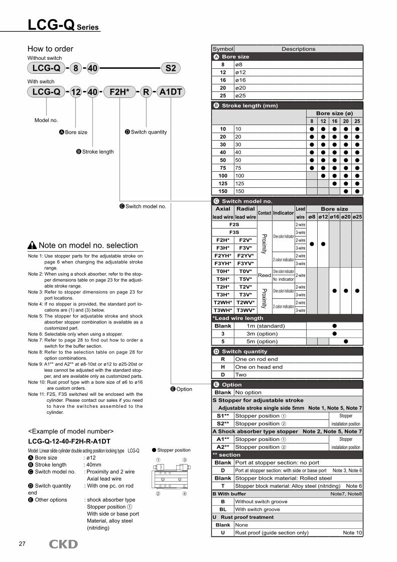
How to orderWithout switch
With switch
LCG-Q S240
Note on model no. selectionNote 1: Use stopper parts for the adjustable stroke on
page 6 when changing the adjustable stroke range.
Note 2: When using a shock absorber, refer to the stop-per dimensions table on page 23 for the adjust-able stroke range.
Note 3: Refer to stopper dimensions on page 23 for port locations.
Note 4: If no stopper is provided, the standard port lo-cations are (1) and (3) below.
Note 5: The stopper for adjustable stroke and shock absorber stopper combination is available as a customized part.
Note 6: Selectable only when using a stopper.Note 7: Refer to page 28 to find out how to order a
switch for the buffer section.Note 8: Refer to the selection table on page 28 for
option combinations.Note 9: A1** and A2** at ø8-10st or ø12 to ø25-20st or
less cannot be adjusted with the standard stop-per, and are available only as customized parts.
Note 10: Rust proof type with a bore size of ø6 to ø16 are custom orders.
Note 11: F2S, F3S switchesl will be enclosed with the cylinder. Please contact our sales if you need to have the switches assembled to the cylinder.
<Example of model number>LCG-Q-12-40-F2H-R-A1DTModel: Linear slide cylinder double acting position locking type LCG-Q A Bore size : ø12B Stroke length : 40mmC Switch model no. : Proximity and 2 wire Axial lead wireD Switch quantity : With one pc. on rod endE Other options : shock absorber type Stopper position 1
With side or base port Material, alloy steel
(nitriding)
8
Model no.
Bore sizeA
Stroke lengthB
LCG-Q 4012 F2H* R A1DT
Switch model no.C
Switch quantityD
E Option
Stopper position
27
Symbol DescriptionsBore size8 ø8
12 ø1216 ø1620 ø2025 ø25
Stroke length (mm)Bore size (ø)
8 12 16 20 2510 1020 2030 3040 4050 5075 75
100 100125 125150 150
Switch model no.Axial
lead wireRadial lead wire
Contact IndicatorLead wire
Bore sizeø8 ø12 ø16 ø20 ø25
F2S
Proximity
One color indicator
2-wireF3S 3-wire
F2H* F2V* 2-wireF3H* F3V* 3-wire
F2YH* F2YV*2 color indicator
2-wireF3YH* F3YV* 3-wireT0H* T0V*
ReedOne color indicator
2-wireT5H* T5V* No indicator
T2H* T2V* Proximity
One color indicator2-wire
T3H* T3V* 3-wireT2WH* T2WV*
2 color indicator2-wire
T3WH* T3WV* 3-wire*Lead wire lengthBlank 1m (standard)
3 3m (option)5 5m (option)
Switch quantityR One on rod endH One on head endD Two
OptionBlank No option
S Stopper for adjustable strokeAdjustable stroke single side 5mm Note 1, Note 5, Note 7S1** Stopper position 1 Stopper
installation positionS2** Stopper position 2
A Shock absorber type stopper Note 2, Note 5, Note 7A1** Stopper position 1 Stopper
installation positionA2** Stopper position 2
** sectionBlank Port at stopper section: no port
D Port at stopper section: with side or base port Note 3, Note 6Blank Stopper block material: Rolled steel
T Stopper block material: Alloy steel (nitriding) Note 6B With buffer Note7, Note8
B Without switch grooveBL With switch groove
U Rust proof treatmentBlank None
U Rust proof (guide section only) Note 10
A
B
C
D
E
1 3
2 4
LCG-Q SeriesHow to order
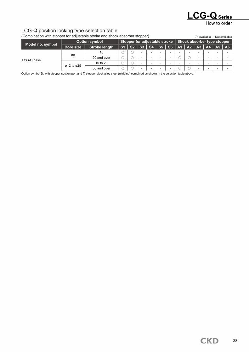
LCG-Q position locking type selection table(Combination with stopper for adjustable stroke and shock absorber stopper) : Available -: Not available
Model no. symbolOption symbol Stopper for adjustable stroke Shock absorber type stopper
Bore size Stroke length S1 S2 S3 S4 S5 S6 A1 A2 A3 A4 A5 A6
LCG-Q baseø8
10 - - - - - - - - - -
20 and over - - - - - - - -
ø12 to ø2510 to 20 - - - - - - - - - -
30 and over - - - - - - - -
Option symbol D: with stopper section port and T: stopper block alloy steel (nitriding) combined as shown in the selection table above.
28
LCG-Q Series
Switch model no.(Page 27 item C )
Switch model no.(Page 27 item C )
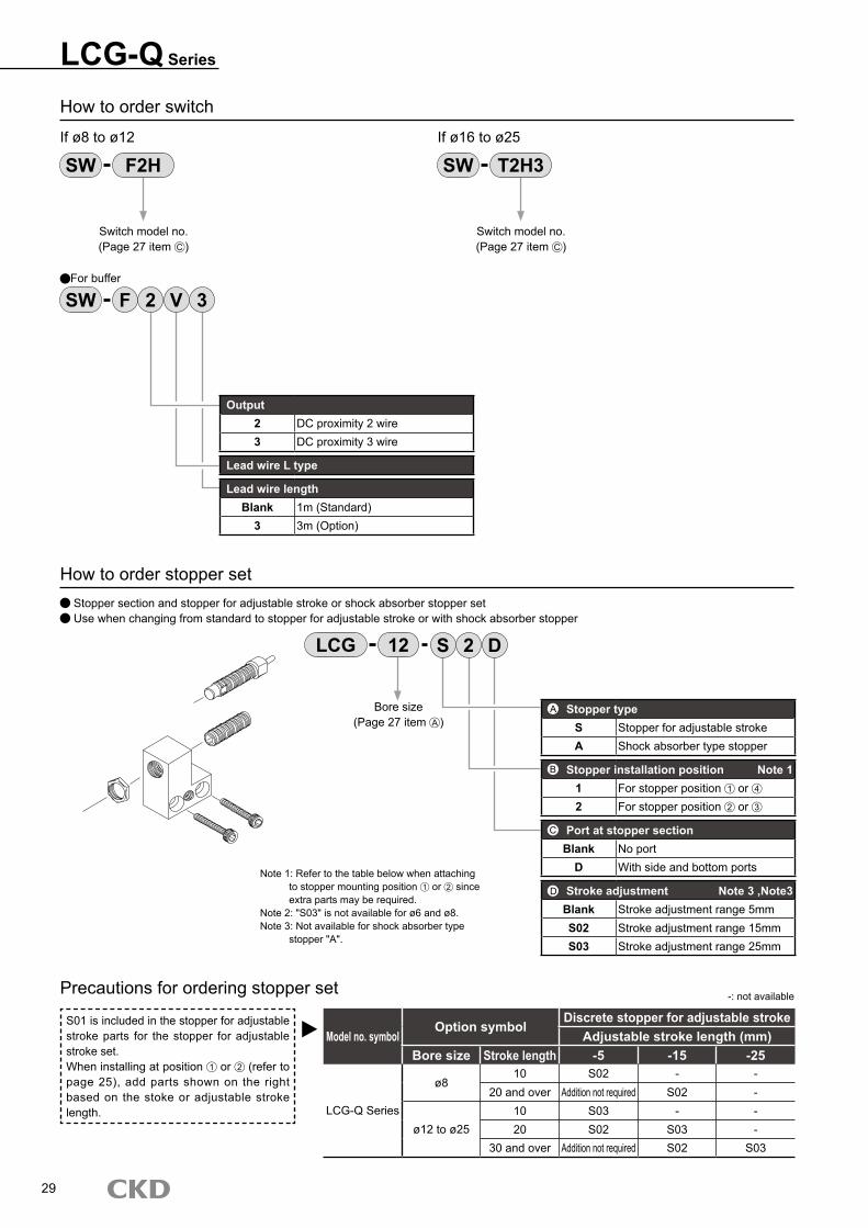
How to order switch
If ø8 to ø12 If ø16 to ø25
How to order stopper set Stopper section and stopper for adjustable stroke or shock absorber stopper set Use when changing from standard to stopper for adjustable stroke or with shock absorber stopper
SW F2H SW T2H3
LCG S12 2 D
Precautions for ordering stopper set
S01 is included in the stopper for adjustable stroke parts for the stopper for adjustable stroke set.When installing at position 1 or 2 (refer to page 25), add parts shown on the right based on the stoke or adjustable stroke length.
Model no. symbolOption symbol
Discrete stopper for adjustable strokeAdjustable stroke length (mm)
Bore size Stroke length -5 -15 -25
LCG-Q Series
ø810 S02 - -
20 and over Addition not required S02 -
ø12 to ø2510 S03 - -20 S02 S03 -
30 and over Addition not required S02 S03
-: not available
29
SW F 2 V 3For buffer
Output2 DC proximity 2 wire3 DC proximity 3 wire
Lead wire L type
Lead wire lengthBlank 1m (Standard)
3 3m (Option)
Stopper typeS Stopper for adjustable strokeA Shock absorber type stopper
Stopper installation position Note 11 For stopper position 1 or 4
2 For stopper position 2 or 3
Port at stopper sectionBlank No port
D With side and bottom ports
Stroke adjustment Note 3 ,Note3Blank Stroke adjustment range 5mmS02 Stroke adjustment range 15mmS03 Stroke adjustment range 25mm
D
Note 1: Refer to the table below when attaching to stopper mounting position 1 or 2 since extra parts may be required.Note 2: "S03" is not available for ø6 and ø8.Note 3: Not available for shock absorber type stopper "A".
Bore size(Page 27 item A )
A
B
C

LCG-Q SeriesHow to order
How to order the discrete stopper for adjustable stroke Hexagon socket head set screw with urethane Use for changing the adjustable stroke range or setting to the middle stroke
Adjustable stroke rangeS01 Single 5mm (standard)S02 Single 15mmS03 Single 25mm
ABore size(Page 25 item A )
LCG 12 S02
Precautions for ordering discrete stopper
Only when installing the discrete stopper for an adjustable stroke or discrete shock absorber stopper at installation position 1 or 2 (refer to page 25), the combination will be as shown on the right depending on the stroke or adjustable stroke length.
Model no. symbolOption symbol
Discrete stopper for adjustable strokeDiscrete shock absorber type stopper
Adjustable stroke length (mm)Bore size Stroke length -5 -15 -25
LCG Series-S1, S2-A1, A2
ø810 S02 - - -
20 and over S01 S02 - A01
ø12 to ø2510 S03 - - -20 S02 S03 - -
30 and over S01 S02 S03 A01
-: combination not available
How to order the discrete shock absorber stopper Sets of shock absorber and stopper cap Use for changing from the stopper for an adjustable stroke to the shock absorber stopper.
Model Shock absorber model no.LCG-8 NCK-00-0.3LCG-12 NCK-00-0.3LCG-16 NCK-00-0.7LCG-20 NCK-00-1.2LCG-25 NCK-00-1.2
Bore size(Page 25 item A )
LCG 12 A01
Discrete stopper block model no. display Use when changing from standard to stopper for adjustable stroke or with shock absorber stopper
Stopper block
SB1ø8: 30 mm stroke or lessø12 to ø25: 50 mm stroke or less
SB2ø8: 40 mm stroke and overø12 to ø25: 75 mm stroke and over
MaterialBlank Stopper block material: Rolled steel
T Stopper block material: Alloy steel (nitriding)
ABore size(Page 27 item A )
LCG 12 SB1
Applicable shock absorber model No.
Note: Some models may not be available depending on the type. Refer to page 25.Refer to page 21 for adjustable stroke range of a shock absorber type stopper.
T
B
Indicate S01, S02 or S03 in A section.Note: S03 is not used for ø8.
Depending on the type, the incompatible models or adjustable stroke ranges may differ from the above values.
30
Shock absorber
Stopper cap
LCG-Q Series
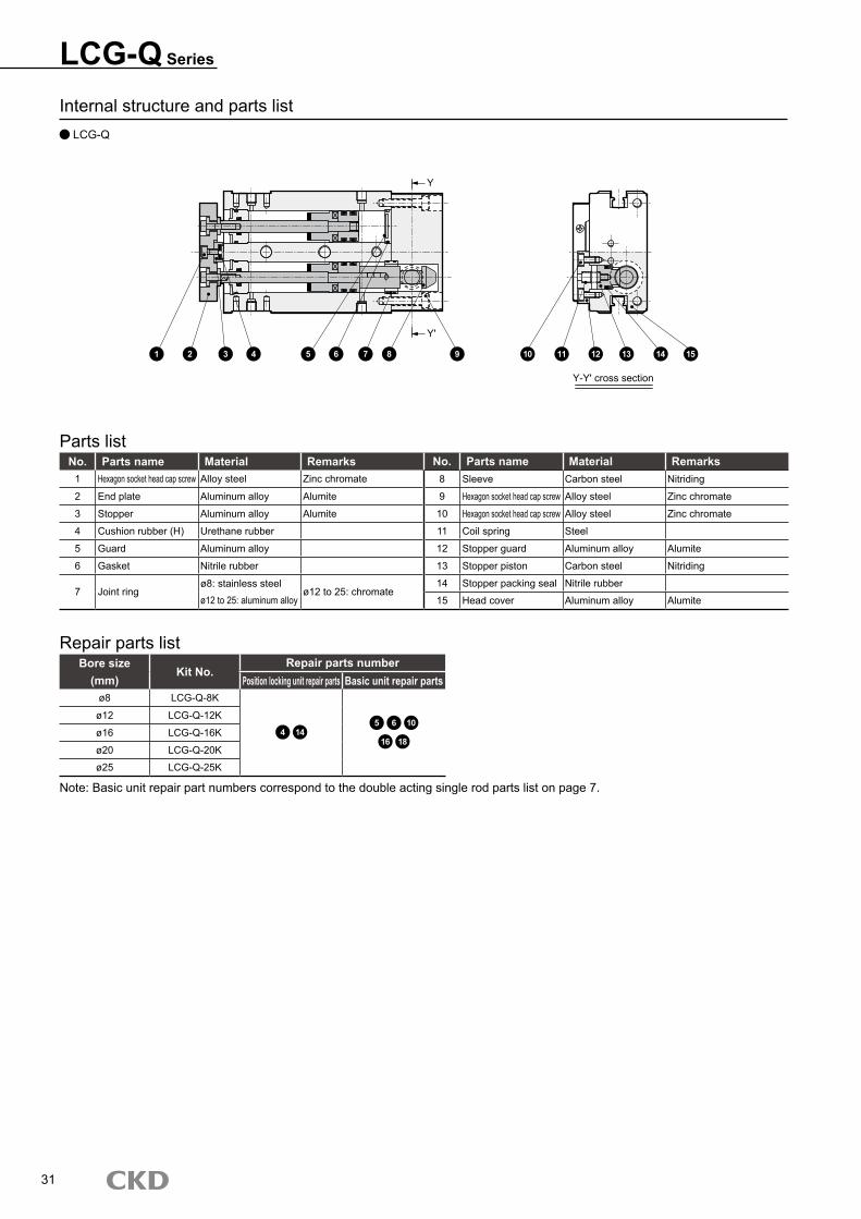
Internal structure and parts list LCG-Q
No. Parts name Material Remarks No. Parts name Material Remarks1 Hexagon socket head cap screw Alloy steel Zinc chromate 8 Sleeve Carbon steel Nitriding
2 End plate Aluminum alloy Alumite 9 Hexagon socket head cap screw Alloy steel Zinc chromate
3 Stopper Aluminum alloy Alumite 10 Hexagon socket head cap screw Alloy steel Zinc chromate
4 Cushion rubber (H) Urethane rubber 11 Coil spring Steel
5 Guard Aluminum alloy 12 Stopper guard Aluminum alloy Alumite
6 Gasket Nitrile rubber 13 Stopper piston Carbon steel Nitriding
7 Joint ringø8: stainless steel
ø12 to 25: chromate14 Stopper packing seal Nitrile rubber
ø12 to 25: aluminum alloy 15 Head cover Aluminum alloy Alumite
Parts list
Bore sizeKit No.
Repair parts number(mm) Position locking unit repair parts Basic unit repair parts
ø8 LCG-Q-8K
4 145 6 10
16 18
ø12 LCG-Q-12K
ø16 LCG-Q-16K
ø20 LCG-Q-20K
ø25 LCG-Q-25K
Repair parts list
Note: Basic unit repair part numbers correspond to the double acting single rod parts list on page 7.
31
Y
Y'
Y-Y' cross section
1 2 3 4 5 6 7 8 9 10 11 12 13 14 15
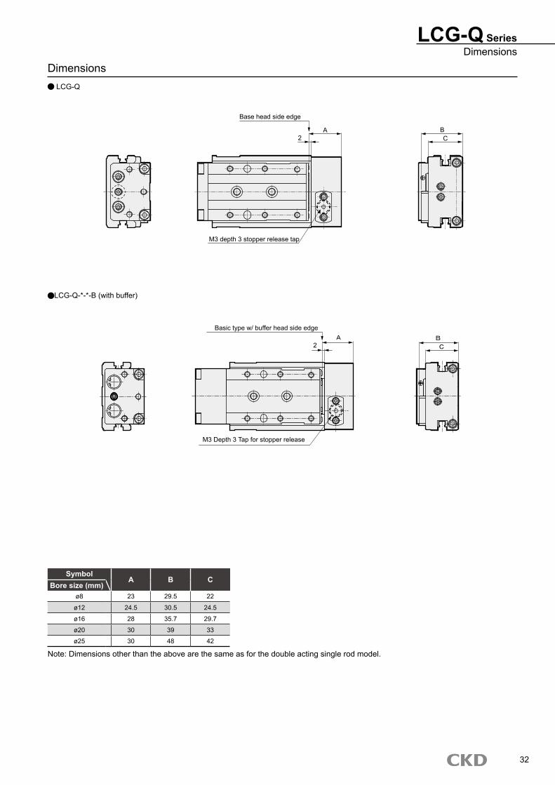
Dimensions LCG-Q
LCG-Q SeriesDimensions
SymbolA B C
Bore size (mm)ø8 23 29.5 22
ø12 24.5 30.5 24.5
ø16 28 35.7 29.7
ø20 30 39 33
ø25 30 48 42
Note: Dimensions other than the above are the same as for the double acting single rod model.
32
LCG-Q-*-*-B (with buffer)
2
Basic type w/ buffer head side edge
M3 Depth 3 Tap for stopper release
A2
BC
Base head side edge
M3 depth 3 stopper release tap
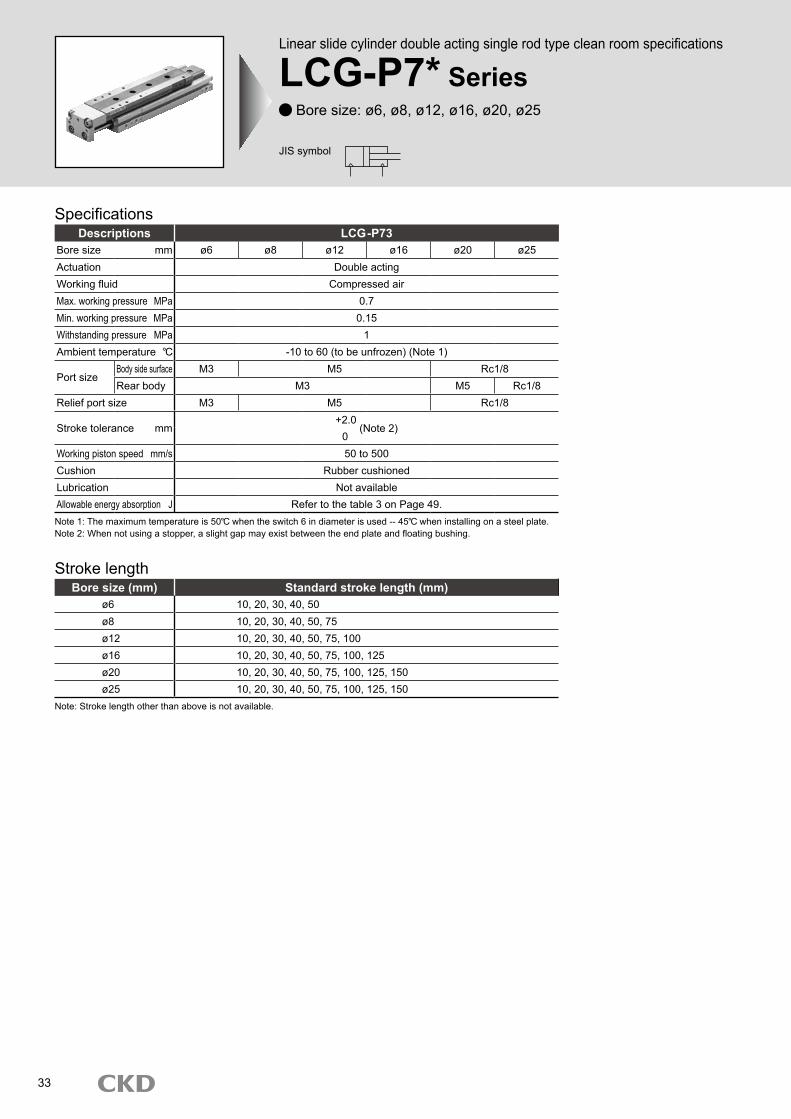
Descriptions LCG-P73Bore size mm ø6 ø8 ø12 ø16 ø20 ø25Actuation Double actingWorking fluid Compressed airMax. working pressure MPa 0.7Min. working pressure MPa 0.15Withstanding pressure MPa 1Ambient temperature -10 to 60 (to be unfrozen) (Note 1)
Port sizeBody side surface M3 M5 Rc1/8Rear body M3 M5 Rc1/8
Relief port size M3 M5 Rc1/8
Stroke tolerance mm+2.0
(Note 2)0
Working piston speed mm/s 50 to 500Cushion Rubber cushionedLubrication Not availableAllowable energy absorption J Refer to the table 3 on Page 49.
Stroke length
Note: Stroke length other than above is not available.
Bore size (mm) Standard stroke length (mm)ø6 10, 20, 30, 40, 50ø8 10, 20, 30, 40, 50, 75ø12 10, 20, 30, 40, 50, 75, 100ø16 10, 20, 30, 40, 50, 75, 100, 125ø20 10, 20, 30, 40, 50, 75, 100, 125, 150ø25 10, 20, 30, 40, 50, 75, 100, 125, 150
Note 1: The maximum temperature is 50 when the switch 6 in diameter is used -- 45 when installing on a steel plate.Note 2: When not using a stopper, a slight gap may exist between the end plate and floating bushing.
Linear slide cylinder double acting single rod type clean room speci-fications
LCG-P7* SeriesBore size: ø6, ø8, ø12, ø16, ø20, ø25
Specifications
JIS symbol
33
Linear slide cylinder double acting single rod type clean room specifications
LCG-P7* Series Bore size: ø6, ø8, ø12, ø16, ø20, ø25
LCG-P7* SeriesSpecifications
(Unit: g)
34
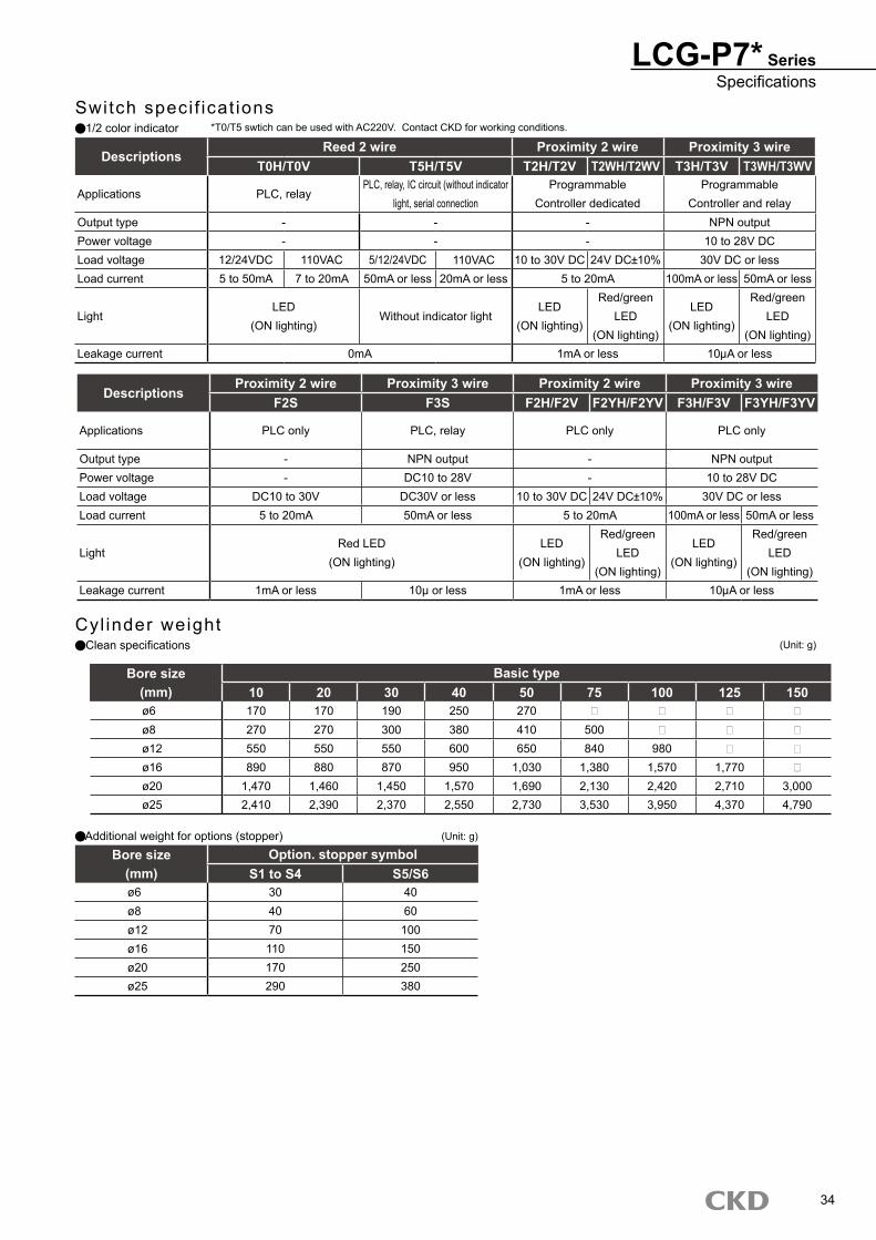
Cyl inder weightClean specifications
Bore size Basic type(mm) 10 20 30 40 50 75 100 125 150ø6 170 170 190 250 270 - - - -ø8 270 270 300 380 410 500 - - -ø12 550 550 550 600 650 840 980 - -ø16 890 880 870 950 1,030 1,380 1,570 1,770 -ø20 1,470 1,460 1,450 1,570 1,690 2,130 2,420 2,710 3,000ø25 2,410 2,390 2,370 2,550 2,730 3,530 3,950 4,370 4,790
Additional weight for options (stopper)Bore size Option. stopper symbol
(mm) S1 to S4 S5/S6ø6 30 40ø8 40 60ø12 70 100ø16 110 150ø20 170 250ø25 290 380
(Unit: g)
Switch speci f icat ions1/2 color indicator
DescriptionsProximity 2 wire Proximity 3 wire Proximity 2 wire Proximity 3 wire
F2S F3S F2H/F2V F2YH/F2YV F3H/F3V F3YH/F3YV
Applications PLC only PLC, relay PLC only PLC only
Output type - NPN output - NPN outputPower voltage - DC10 to 28V - 10 to 28V DCLoad voltage DC10 to 30V DC30V or less 10 to 30V DC 24V DC 10% 30V DC or lessLoad current 5 to 20mA 50mA or less 5 to 20mA 100mA or less 50mA or less
LightRed LED
(ON lighting)LED
(ON lighting)
Red/greenLED
(ON lighting)
LED (ON lighting)
Red/greenLED
(ON lighting)Leakage current 1mA or less 10μ or less 1mA or less 10 A or less
DescriptionsReed 2 wire Proximity 2 wire Proximity 3 wire
T0H/T0V T5H/T5V T2H/T2V T2WH/T2WV T3H/T3V T3WH/T3WV
Applications PLC, relayPLC, relay, IC circuit (without indicator
light, serial connectionProgrammable
Controller dedicatedProgrammable
Controller and relayOutput type - - - NPN outputPower voltage - - - 10 to 28V DCLoad voltage 12/24VDC 110VAC 5/12/24VDC 110VAC 10 to 30V DC 24V DC 10% 30V DC or lessLoad current 5 to 50mA 7 to 20mA 50mA or less 20mA or less 5 to 20mA 100mA or less 50mA or less
LightLED
(ON lighting)Without indicator light
LED (ON lighting)
Red/greenLED
(ON lighting)
LED (ON lighting)
Red/greenLED
(ON lighting)Leakage current 0mA 1mA or less 10 A or less
*T0/T5 swtich can be used with AC220V. Contact CKD for working conditions.
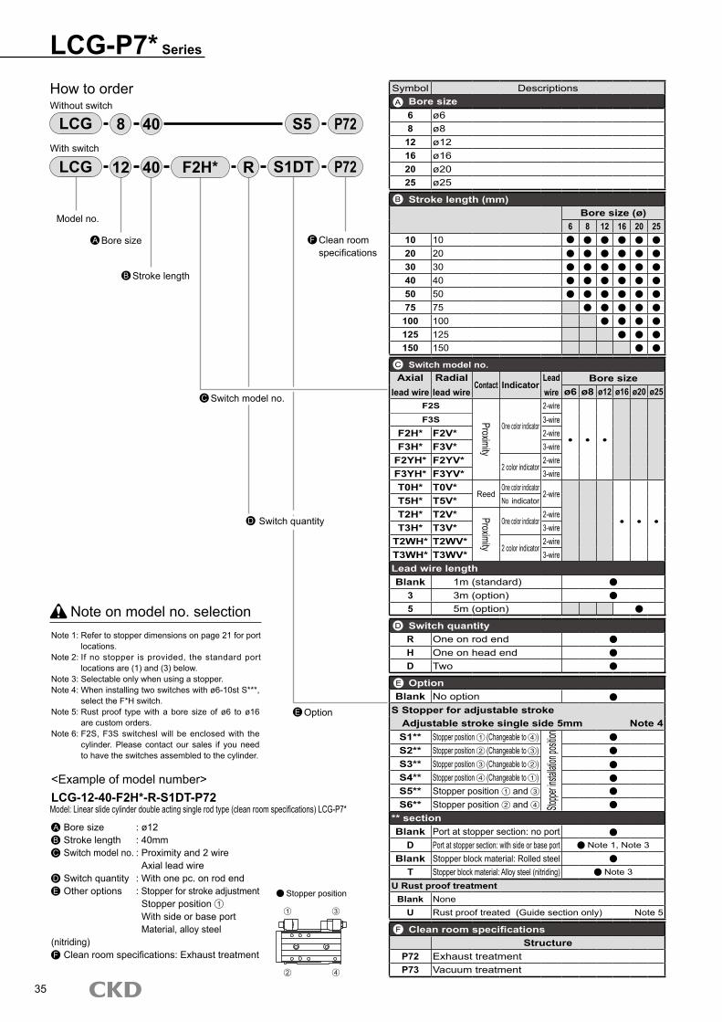
Switch quantityD
LCG-P7* Series
E
How to orderWithout switch
With switch
Note on model no. selectionNote 1: Refer to stopper dimensions on page 21 for port
locations.Note 2: If no stopper is provided, the standard port
locations are (1) and (3) below.Note 3: Selectable only when using a stopper.Note 4: When installing two switches with ø6-10st S***,
select the F*H switch.Note 5: Rust proof type with a bore size of ø6 to ø16
are custom orders.Note 6: F2S, F3S switchesl will be enclosed with the
cylinder. Please contact our sales if you need to have the switches assembled to the cylinder.
<Example of model number>LCG-12-40-F2H*-R-S1DT-P72
A Bore size : ø12B Stroke length : 40mmC Switch model no. : Proximity and 2 wire Axial lead wireD Switch quantity : With one pc. on rod endE Other options : Stopper for stroke adjustment Stopper position 1
With side or base port Material, alloy steel (nitriding)F Clean room specifications: Exhaust treatment
LCG S5408
Model no.
Bore sizeA
Stroke lengthB
LCG 4012 F2H* R S1DT
Switch model no.C
Option
Stopper position
P72
P72
Clean room specifications
F
Symbol DescriptionsBore size6 ø68 ø8
12 ø1216 ø1620 ø2025 ø25
Stroke length (mm)Bore size (ø)
6 8 12 16 20 2510 1020 2030 3040 4050 5075 75
100 100125 125150 150
Switch model no.Axial
lead wireRadial lead wire
Contact IndicatorLead wire
Bore sizeø6 ø8 ø12 ø16 ø20 ø25
F2S
Proximity
One color indicator
2-wire
● ● ●
F3S 3-wireF2H* F2V* 2-wireF3H* F3V* 3-wire
F2YH* F2YV*2 color indicator
2-wireF3YH* F3YV* 3-wireT0H* T0V*
ReedOne color indicator
2-wire
● ● ●
T5H* T5V* No indicator
T2H* T2V* Proximity
One color indicator2-wire
T3H* T3V* 3-wireT2WH* T2WV*
2 color indicator2-wire
T3WH* T3WV* 3-wireLead wire lengthBlank 1m (standard)
3 3m (option)5 5m (option)
Switch quantityR One on rod endH One on head endD Two
OptionBlank No option
S Stopper for adjustable strokeAdjustable stroke single side 5mm Note 4S1** Stopper position 1 (Changeable to 4 )
Stoppe
r insta
llation
positio
n
S2** Stopper position 2 (Changeable to 3 )S3** Stopper position 3 (Changeable to 2 )S4** Stopper position 4 (Changeable to 1 )S5** Stopper position 1 and 3
S6** Stopper position 2 and 4
** sectionBlank Port at stopper section: no port
D Port at stopper section: with side or base port Note 1, Note 3
Blank Stopper block material: Rolled steelT Stopper block material: Alloy steel (nitriding) Note 3
U Rust proof treatmentBlank None
U Rust proof treated (Guide section only) Note 5
Clean room specificationsStructure
P72 Exhaust treatmentP73 Vacuum treatment
35
Model: Linear slide cylinder double acting single rod type (clean room specifications) LCG-P7*
A
B
C
D
E
F
1
4
3
2

36
M E M OM E M O
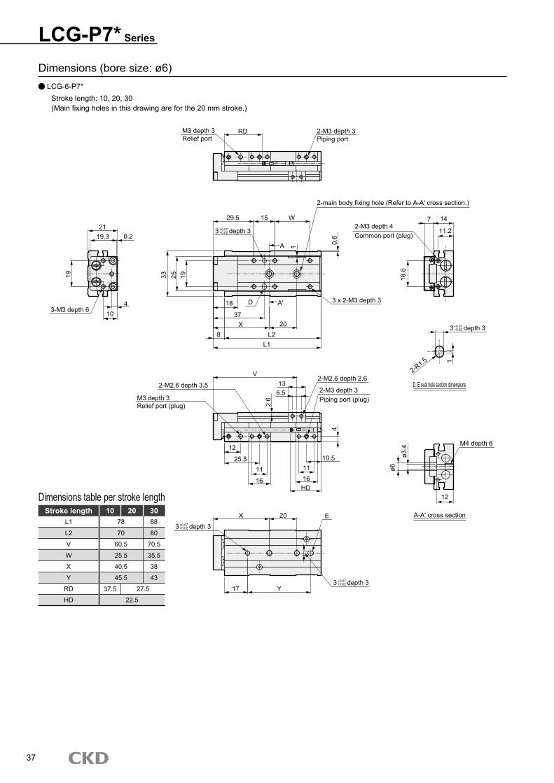
LCG-P7* Series
Stroke length 10 20 30L1 78 88
L2 70 80
V 60.5 70.5
W 25.5 35.5
X 40.5 38
Y 45.5 43
RD 37.5 27.5
HD 22.5
Dimensions table per stroke length
Dimensions (bore size: ø6) LCG-6-P7*
Stroke length: 10, 20, 30(Main fixing holes in this drawing are for the 20 mm stroke.)
37
M3 depth 3Relief port
2-M3 depth 3Piping port
RD
29.5 15 W
A 1 0.6
3 depth 3
33 25 19
2-main body fixing hole (Refer to A-A' cross section.)
2-M3 depth 4Common port (plug)
7 14
11.2
18.6
3 x 2-M3 depth 3
20L2
L1
37
18 D
X8
A'
19.321
0.2
19
104
3-M3 depth 6
3 depth 3
D, E oval hole section dimensions
2-R1.5 1
2-M2.6 depth 2.6
2-M3 depth 3Piping port (plug)
2-M2.6 depth 3.5
M3 depth 3Relief port (plug)
V13
6.5
2.6
25.5
12
11
16
1116
10.5
HD
4
ø3.4
ø6
M4 depth 6
12
A-A' cross sectionE20X
3 depth 3
Y173 depth 3
+0.07+0.02
+0.07+0.02
+0.07+0.02
+0.07+0.02
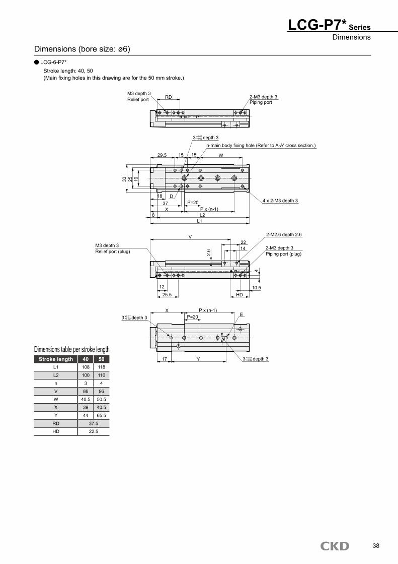
Dimensions (bore size: ø6) LCG-6-P7*
Stroke length: 40, 50(Main fixing holes in this drawing are for the 50 mm stroke.)
LCG-P7* SeriesDimensions
Stroke length 40 50L1 108 118
L2 100 110
n 3 4
V 86 96
W 40.5 50.5
X 39 40.5
Y 44 65.5
RD 37.5
HD 22.5
Dimensions table per stroke length
38
RDM3 depth 3Relief port 2-M3 depth 3
Piping port
3 depth 3
29.5 15 15 W
33 25 19
18 D37X
8
n-main body fixing hole (Refer to A-A' cross section.)
P=20P x (n-1)L2
L1
V
4 x 2-M3 depth 3
2-M2.6 depth 2.6
2-M3 depth 3Piping port (plug)
2214
2.6
12
25.510.5
HD
4
M3 depth 3Relief port (plug)
P=20P x (n-1)X
3 depth 3 E
3 depth 3Y17
+0.07+0.02
+0.07+0.02
+0.07+0.02
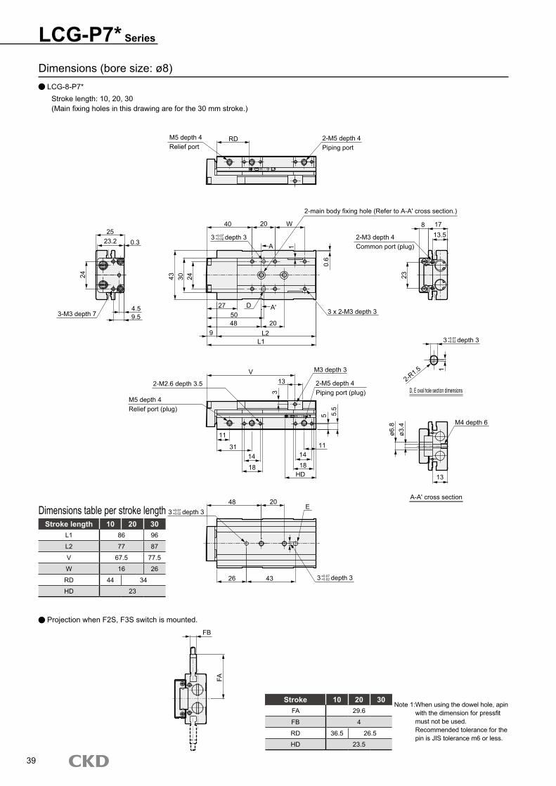
Dimensions (bore size: ø8) LCG-8-P7*
Stroke length: 10, 20, 30(Main fixing holes in this drawing are for the 30 mm stroke.)
Stroke length 10 20 30L1 86 96
L2 77 87
V 67.5 77.5
W 16 26
RD 44 34
HD 23
Dimensions table per stroke length
LCG-P7* Series
39
Stroke 10 20 30FA 29.6
FB 4
RD 36.5 26.5
HD 23.5
FB
FA
Note 1: When using the dowel hole, apin with the dimension for pressfit must not be used. Recommended tolerance for the pin is JIS tolerance m6 or less.
Projection when F2S, F3S switch is mounted.
M5 depth 4Relief port
2-M5 depth 4Piping port
RD
40 20 W
A 1
0.6
3 depth 3
43 30 24
2-main body fixing hole (Refer to A-A' cross section.)
2-M3 depth 4Common port (plug)
8 1713.5
23
3 x 2-M3 depth 3
20L2
L1
5027 D
489
A'
23.225
0.3
24
9.54.5
3-M3 depth 7
3 depth 3
D, E oval hole section dimensions2-R1.5 1M3 depth 3
2-M5 depth 4Piping port (plug)
2-M2.6 depth 3.5
M5 depth 4Relief port (plug)
V13
3
11
14
18HD
11
5
ø3.4
ø6.8 M4 depth 6
13
A-A' cross sectionE
20483 depth 3
4326 3 depth 3
31
5.5
1418
+0.07+0.02
+0.07+0.02
+0.07+0.02
+0.07+0.02
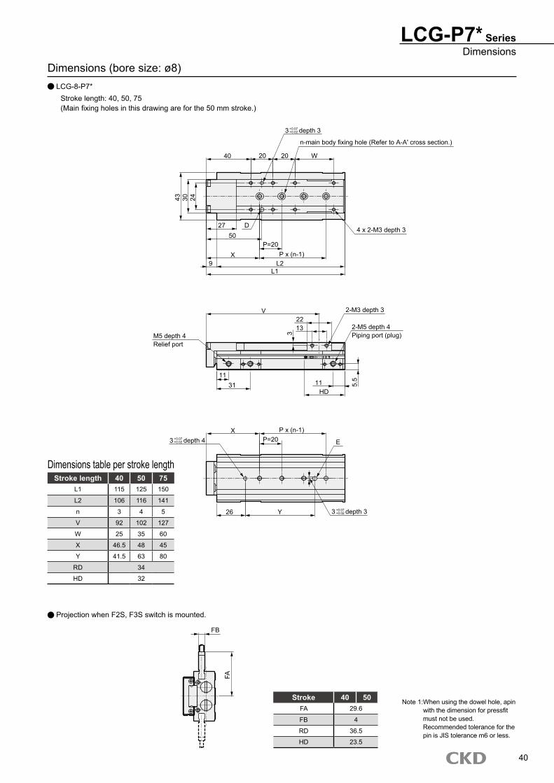
Dimensions (bore size: ø8) LCG-8-P7*
Stroke length: 40, 50, 75(Main fixing holes in this drawing are for the 50 mm stroke.)
Stroke length 40 50 75L1 115 125 150
L2 106 116 141
n 3 4 5
V 92 102 127
W 25 35 60
X 46.5 48 45
Y 41.5 63 80
RD 34
HD 32
Dimensions table per stroke length
LCG-P7* SeriesDimensions
40
Stroke 40 50FA 29.6
FB 4
RD 36.5
HD 23.5
FB
FA
Note 1: When using the dowel hole, apin with the dimension for pressfit must not be used. Recommended tolerance for the pin is JIS tolerance m6 or less.
Projection when F2S, F3S switch is mounted.
3 depth 3
40 20 W
43 30 24
27 D50
X9
n-main body fixing hole (Refer to A-A' cross section.)
P=20P x (n-1)
L2L1
V
4 x 2-M3 depth 3
2-M3 depth 3
2-M5 depth 4Piping port (plug)
2213
3
1131 11
HD
5.5
M5 depth 4Relief port
P=20P x (n-1)X
3 depth 4 E
3 depth 3Y26
20
+0.07+0.02
+0.07+0.02
+0.07+0.02
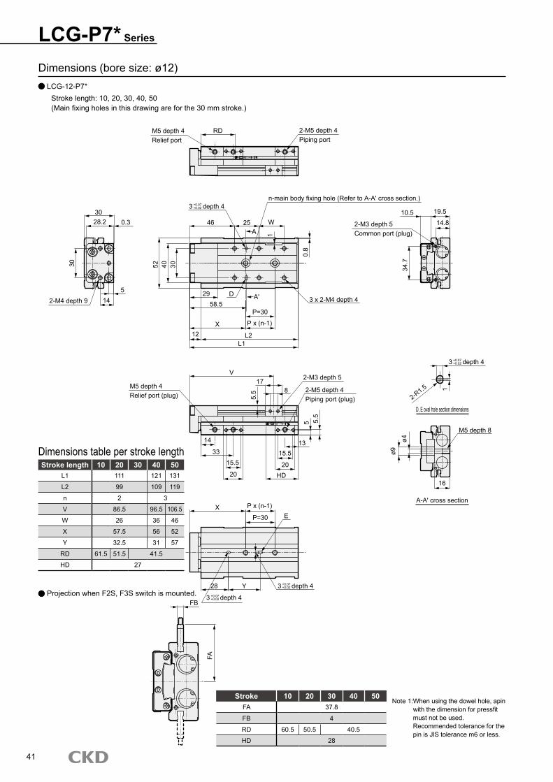
Dimensions (bore size: ø12) LCG-12-P7*
Stroke length: 10, 20, 30, 40, 50(Main fixing holes in this drawing are for the 30 mm stroke.)
Stroke length 10 20 30 40 50L1 111 121 131
L2 99 109 119
n 2 3
V 86.5 96.5 106.5
W 26 36 46
X 57.5 56 52
Y 32.5 31 57
RD 61.5 51.5 41.5
HD 27
Dimensions table per stroke length
LCG-P7* Series
41
Stroke 10 20 30 40 50FA 37.8
FB 4
RD 60.5 50.5 40.5
HD 28
FB
FA
Note 1: When using the dowel hole, apin with the dimension for pressfit must not be used. Recommended tolerance for the pin is JIS tolerance m6 or less.
Projection when F2S, F3S switch is mounted.
M5 depth 4Relief port
2-M5 depth 4Piping port
RD
46 25 WA 1
0.8
3 depth 4
52 40 30
n-main body fixing hole (Refer to A-A' cross section.)
2-M3 depth 5Common port (plug)
10.5 19.5
14.8
34.7
3 x 2-M4 depth 4
L2L1
58.529 D
X12
A'
28.230
0.3
30
145
2-M4 depth 9
3 depth 4
D, E oval hole section dimensions
2-R1.5 1
2-M3 depth 5
2-M5 depth 4Piping port (plug)
M5 depth 4Relief port (plug)
V17
5.5
14
15.5
20 HD
13
5
ø4
ø9
M5 depth 8
16
A-A' cross section
EX
3 depth 4
Y28 3 depth 4
33
5.5
15.5
20
P=30
P x (n-1)
P=30
P x (n-1)
8
+0.07+0.02
+0.07+0.02
+0.07+0.02
+0.07+0.02
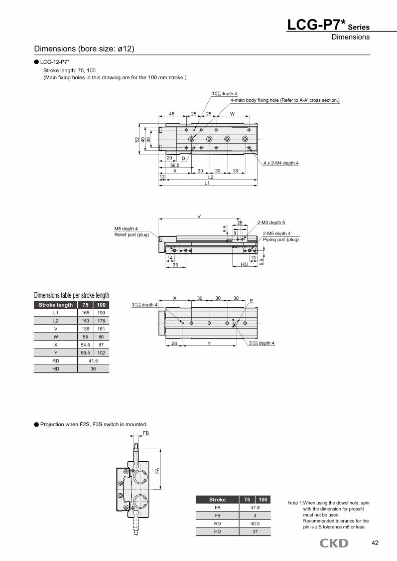
Dimensions (bore size: ø12) LCG-12-P7*
Stroke length: 75, 100(Main fixing holes in this drawing are for the 100 mm stroke.)
Stroke length 75 100L1 165 190
L2 153 178
V 136 161
W 55 80
X 54.5 67
Y 89.5 102
RD 41.5
HD 36
Dimensions table per stroke length
LCG-P7* SeriesDimensions
42
Stroke 75 100FA 37.8
FB 4
RD 40.5
HD 37
FB
FA
Note 1: When using the dowel hole, apin with the dimension for pressfit must not be used. Recommended tolerance for the pin is JIS tolerance m6 or less.
Projection when F2S, F3S switch is mounted.
3 depth 4
46 25 W
52 40 30
29 D58.5
X12
4-main body fixing hole (Refer to A-A' cross section.)
30L2
L1
V
4 x 2-M4 depth 4
2-M3 depth 5
2-M5 depth 4Piping port (plug)
26
85.5
1433
13HD 5.
5
M5 depth 4Relief port (plug)
30X3 depth 4
E
3 depth 4Y28
25
3030
30 30
+0.07+0.02
+0.07+0.02
+0.07+0.02
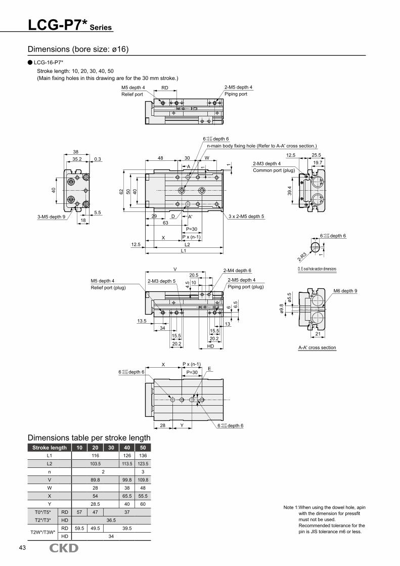
Dimensions (bore size: ø16) LCG-16-P7*
Stroke length: 10, 20, 30, 40, 50(Main fixing holes in this drawing are for the 30 mm stroke.)
Stroke length 10 20 30 40 50L1 116 126 136
L2 103.5 113.5 123.5
n 2 3
V 89.8 99.8 109.8
W 28 38 48
X 54 65.5 55.5
Y 28.5 40 60
T0*/T5* RD 57 47 37
T2*/T3* HD 36.5
T2W*/T3W*RD 59.5 49.5 39.5
HD 34
Dimensions table per stroke length
LCG-P7* Series
43
Note 1: When using the dowel hole, apin with the dimension for pressfit must not be used. Recommended tolerance for the pin is JIS tolerance m6 or less.
M5 depth 4Relief port
2-M5 depth 4Piping port
RD
48 30 W
A 1 1
6 depth 6
62 50 40
n-main body fixing hole (Refer to A-A' cross section.)
2-M3 depth 4Common port (plug)
12.519.725.5
39.4
3 x 2-M5 depth 5
L2L1
6329 D
X12.5
A'
35.238
0.3
40
18
5.53-M5 depth 9
6 depth 6
D, E oval hole section dimensions
2-R3 1
2-M4 depth 6
2-M5 depth 4Piping port (plug)
2-M3 depth 5M5 depth 4Relief port (plug)
V20.5
4.5
13.5
15.5
20.2 HD
13
6
ø5.5
ø9.8
M6 depth 9
21
A-A' cross section
EX
6 depth 6
Y28 6 depth 6
34
6.5
15.520.2
P=30P x (n-1)
P=30
P x (n-1)
10
+0.07+0.02
+0.07+0.02
+0.07+0.02
+0.07+0.02
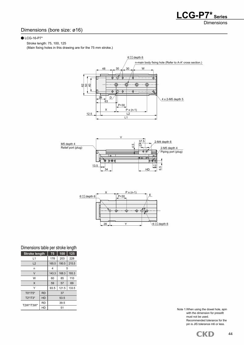
Dimensions (bore size: ø16) LCG-16-P7*
Stroke length: 75, 100, 125(Main fixing holes in this drawing are for the 75 mm stroke.)
Stroke length 75 100 125L1 178 203 228
L2 165.5 190.5 215.5
n 4 5
V 143.3 168.3 193.3
W 60 85 110
X 59 57 69
Y 93.5 121.5 133.5
T0*/T5* RD 37
T2*/T3* HD 53.5
T2W*/T3W*RD 39.5
HD 51
Dimensions table per stroke length
LCG-P7* SeriesDimensions
44
Note 1: When using the dowel hole, apin with the dimension for pressfit must not be used. Recommended tolerance for the pin is JIS tolerance m6 or less.
6 depth 6
48 30 W
62 50 40
29 D63
X12.5
n-main body fixing hole (Refer to A-A' cross section.)
L2L1
V
4 x 2-M5 depth 5
2-M4 depth 6
2-M5 depth 4Piping port (plug)
37.5104.
5
13.534
13HD 6.
5
M5 depth 4Relief port (plug)
X6 depth 6 E
6 depth 6Y28
30
P x (n-1)P=30
P x (n-1)P=30
+0.07+0.02
+0.07+0.02
+0.07+0.02
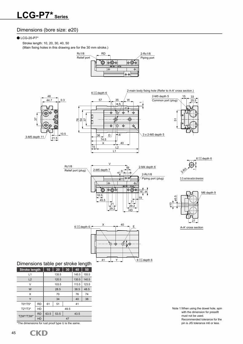
Dimensions (bore size: ø20) LCG-20-P7*
Stroke length: 10, 20, 30, 40, 50(Main fixing holes in this drawing are for the 30 mm stroke.)
Stroke length 10 20 30 40 50L1 135.5 145.5 155.5
L2 120.5 130.5 140.5
V 103.5 113.5 123.5
W 28.5 38.5 48.5
X 70 76 74
Y 34 40 38
T0*/T5* RD 61 51 41
T2*/T3* HD 49.5
T2W*/T3W*RD 63.5 53.5 43.5
HD 47
Dimensions table per stroke length
LCG-P7* Series
45
Note 1: When using the dowel hole, apin with the dimension for pressfit must not be used. Recommended tolerance for the pin is JIS tolerance m6 or less.*The dimensions for rust proof type U is the same.
6 depth 6
Rc1/8Relief port
RD 2-Rc1/8Piping port
6 depth 62-main body fixing hole (Refer to A-A' cross section.)
57 35 WA 1
1
76 54 37
36 D A' 74.5X
15 L2L1
40
3 x 2-M5 depth 5
2-M5 depth 5Common port (plug)
15 3325.5
512-R
3
D, E oval hole section dimensions
1M6 depth 9
ø5.5
ø10
27
A-A' cross section
2-M4 depth 6
2-Rc1/8Piping port (plug)
V19
96
2-M5 depth 7Rc1/8Relief port (plug)
98
1921
29.2HD
18.5
45.521
29.2
4844.7 0.3
10.521.5
37
3-M5 depth 11
6 depth 6X 40 E
6 depth 641 Y
+0.07+0.02
+0.07+0.02
+0.07+0.02
+0.07+0.02
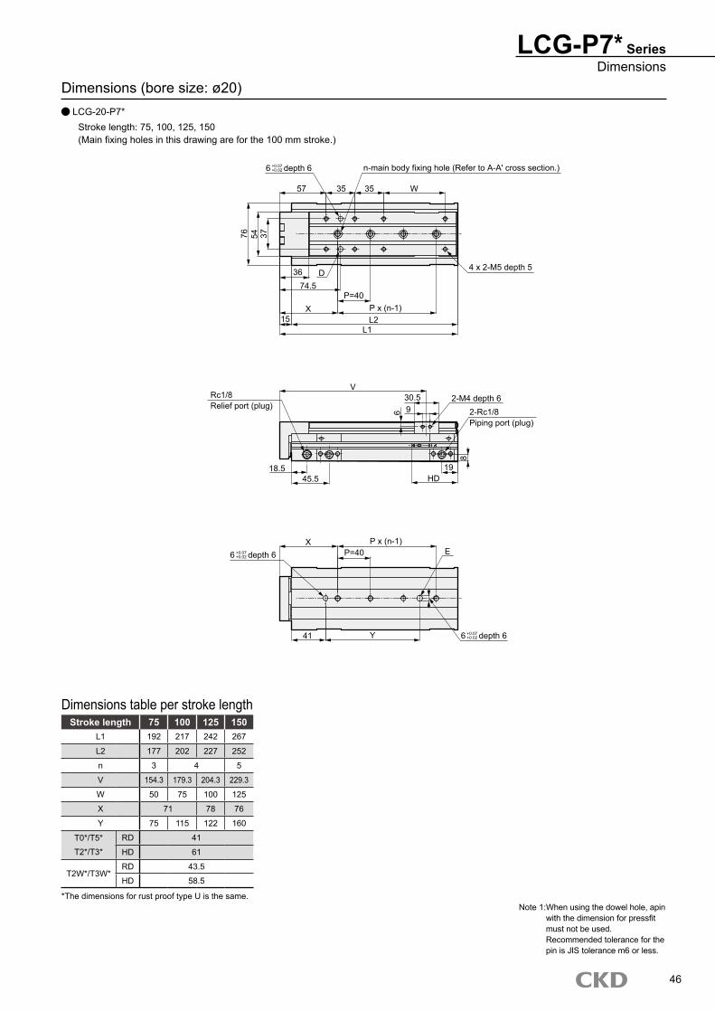
Dimensions (bore size: ø20) LCG-20-P7*
Stroke length: 75, 100, 125, 150(Main fixing holes in this drawing are for the 100 mm stroke.)
Stroke length 75 100 125 150L1 192 217 242 267
L2 177 202 227 252
n 3 4 5
V 154.3 179.3 204.3 229.3
W 50 75 100 125
X 71 78 76
Y 75 115 122 160
T0*/T5* RD 41
T2*/T3* HD 61
T2W*/T3W*RD 43.5
HD 58.5
Dimensions table per stroke length
LCG-P7* SeriesDimensions
46
Note 1: When using the dowel hole, apin with the dimension for pressfit must not be used. Recommended tolerance for the pin is JIS tolerance m6 or less.
*The dimensions for rust proof type U is the same.
6 depth 6 n-main body fixing hole (Refer to A-A' cross section.)
57 35 35 W
4 x 2-M5 depth 5
76 54 3736 D
74.5P=40
X P x (n-1)15 L2
L1
V30.59
2-M4 depth 66 2-Rc1/8
Piping port (plug)
819
HD18.5
45.5
Rc1/8Relief port (plug)
6 depth 6X P x (n-1)
P=40 E
6 depth 6Y41
+0.07+0.02
+0.07+0.02
+0.07+0.02
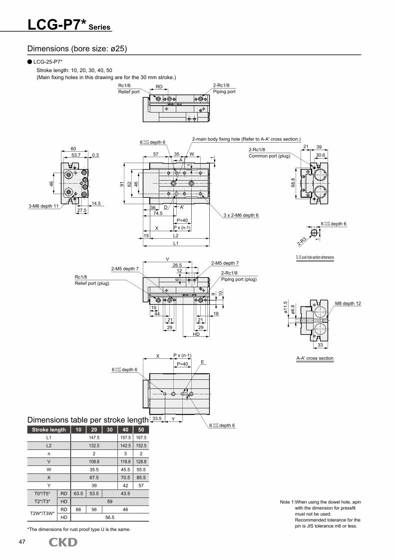
Dimensions (bore size: ø25) LCG-25-P7*
Stroke length: 10, 20, 30, 40, 50(Main fixing holes in this drawing are for the 30 mm stroke.)
Stroke length 10 20 30 40 50L1 147.5 157.5 167.5
L2 132.5 142.5 152.5
n 2 3 2
V 108.8 118.8 128.8
W 35.5 45.5 55.5
X 67.5 70.5 85.5
Y 39 42 57
T0*/T5* RD 63.5 53.5 43.5
T2*/T3* HD 59
T2W*/T3W*RD 66 56 46
HD 56.5
Dimensions table per stroke length
LCG-P7* Series
47
Note 1: When using the dowel hole, apin with the dimension for pressfit must not be used. Recommended tolerance for the pin is JIS tolerance m6 or less.
*The dimensions for rust proof type U is the same.
6 depth 6
Rc1/8Relief port
RD 2-Rc1/8Piping port
2-main body fixing hole (Refer to A-A' cross section.)
57 35 WA 1
1
91 62 46
3 x 2-M6 depth 636 D A'
74.5P=40
P x (n-1)
L2L1
X15
2-Rc1/8Common port (plug)
21 39
30.6
68.8
6 depth 6
2-R3
D, E oval hole section dimensions
1
6053.7 0.3
46
14.527.5
3-M6 depth 11
2-M5 depth 7
Rc1/8Relief port (plug)
V26.5
122-M5 depth 7
2-Rc1/8Piping port (plug)6
9 10
1919
21212929
HD
44
6 depth 6
6 depth 6
X P x (n-1)
P=40 E
33.5 Y
ø11.
5ø6
.8
M8 depth 12
33
A-A' cross section
+0.07+0.02
+0.07+0.02
+0.07+0.02
+0.07+0.02
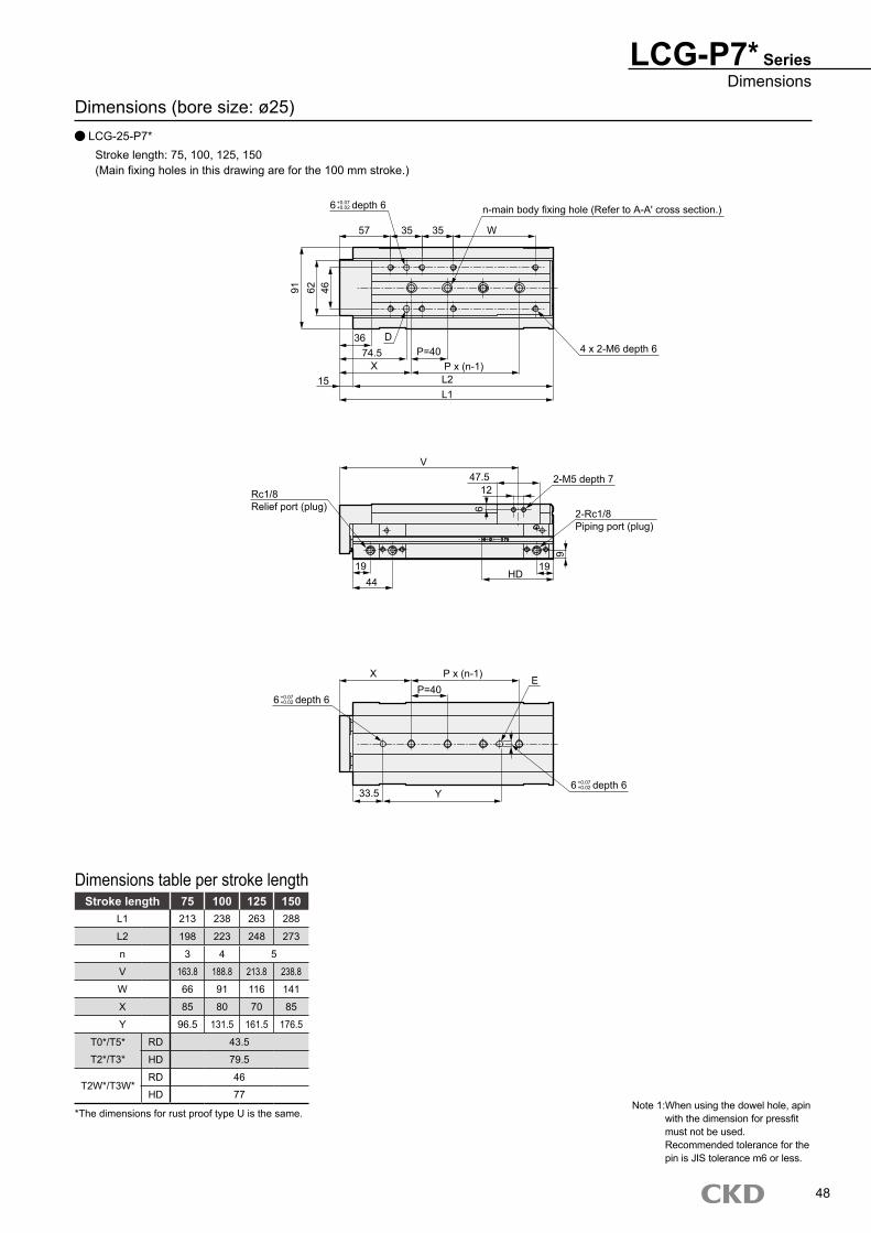
Dimensions (bore size: ø25) LCG-25-P7*
Stroke length: 75, 100, 125, 150(Main fixing holes in this drawing are for the 100 mm stroke.)
Stroke length 75 100 125 150L1 213 238 263 288
L2 198 223 248 273
n 3 4 5
V 163.8 188.8 213.8 238.8
W 66 91 116 141
X 85 80 70 85
Y 96.5 131.5 161.5 176.5
T0*/T5* RD 43.5
T2*/T3* HD 79.5
T2W*/T3W*RD 46
HD 77
Dimensions table per stroke length
LCG-P7* SeriesDimensions
48
Note 1: When using the dowel hole, apin with the dimension for pressfit must not be used. Recommended tolerance for the pin is JIS tolerance m6 or less.
*The dimensions for rust proof type U is the same.
6 depth 6 n-main body fixing hole (Refer to A-A' cross section.)
57 35 35 W
91 62 4636 D
X15
74.5 P=40P x (n-1)L2L1
4 x 2-M6 depth 6
V47.5
12
2-Rc1/8Piping port (plug)
62-M5 depth 7
919
HD19
44
Rc1/8Relief port (plug)
X
6 depth 6
P x (n-1)P=40
E
33.5 Y6 depth 6
+0.07+0.02
+0.07+0.02
+0.07+0.02
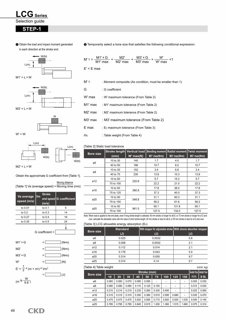
LCG SeriesSelection guide
STEP-1
1 Obtain the load and impact moment generated in each direction at the stroke end.
2 Temporarily select a bore size that satisfies the following conditional expression:
M' T = M1' GM1' max
+ M2' M2' max
+ M3' GM3' max
+ W' W' max
<1
E' < E max
M' T : Moment composite (As condition, must be smaller than 1)
G : G coefficient
W' max : W' maximum tolerance (From Table 2)
M1' max : M1' maximum tolerance (From Table 2)
M2' max : M2' maximum tolerance (From Table 2)
M3' max : M3' maximum tolerance (From Table 2)
E max : E0 maximum tolerance (From Table 3)
m : Table weight (From Table 4)
M1' = L W
M3' = L W
W' = W
M2' = L W
Obtain the approximate G coefficient from [Table 1].
[Table 1] Va (average speed) = Moving distanceMoving time (m/s)
Va average speed (m/s)
VmStroke end speed G coefficient(m/s)
to 0.07 to 0.1 5
to 0.2 to 0.3 14
to 0.27 to 0.4 19
to 0.35 to 0.5 24
G coefficient =
M1' G = (N m)
M2' = (N m)
M3' G = (N m)
W' = (N)
E' = 12 (m + m ) Vm2
= (J)
(m W9.8 )
[Table 2] Static load tolerance
Bore sizeStroke length Vertical load Bending moment Radial moment Twist moment
(mm) W' max(N) M1' max(N m) M2' max(N m) M3' max(N m)
ø610 to 30 140 1.7 4.0 1.7
40 to 50 186 10.7 6.0 10.7
ø810 to 30 152 3.4 6.8 3.4
40 to 75 230 13.8 10.3 13.8
ø1210 to 50
220.85.7 15.2 5.7
75 to 100 22.2 21.0 22.2
ø1610 to 50
380.817.8 36.0 17.8
75 to 125 37.3 40.0 37.3
ø2010 to 50
548.831.1 60.3 31.1
75 to 150 56.2 61.6 56.2
ø2510 to 50
961.565.1 131.8 65.1
75 to 150 127.5 132.0 127.5
[Table 3] LCG allowable energy absorption (E0)
Bore sizeStandard With stopper for adjustable stroke With shock absorber stopper
(J) (J) (J)ø6 0.025 0.0032 0.6
ø8 0.058 0.0032 2.1
ø12 0.112 0.014 2.1
ø16 0.176 0.043 5.4
ø20 0.314 0.055 9.7
ø25 0.314 0.14 9.7
[Table 4] Table weight (Unit: kg)
49
Note: When load is applied to the end plate, even if long stroke length is selected; 40 mm stroke or longer for ø6.8, or 75 mm stroke or longer for ø12 and over, calculate the allowable valve with the value of short stroke length; 30 mm stroke or less for ø6.8, or 50 mm stroke or less for ø12 and over.
Bore sizeStroke (mm) Add for
P72 P73Add forB BL10 20 30 40 50 75 100 125 150
ø6 0.060 0.060 0.070 0.085 0.095 - - - - 0.005 0.030
ø8 0.080 0.080 0.090 0.110 0.125 0.150 - - - 0.015 0.030
ø12 0.210 0.210 0.210 0.235 0.260 0.335 0.400 - - 0.025 0.060
ø16 0.315 0.315 0.315 0.350 0.380 0.515 0.595 0.680 - 0.035 0.070
ø20 0.475 0.475 0.475 0.520 0.565 0.715 0.820 0.930 1.035 0.045 0.140
ø25 0.785 0.785 0.785 0.845 0.915 1.200 1.360 1.515 1.680 0.075 0.310
W(N)
L(m)
W(N)
L(m)
W
W(N)
L(m)
W(N)
L(m)
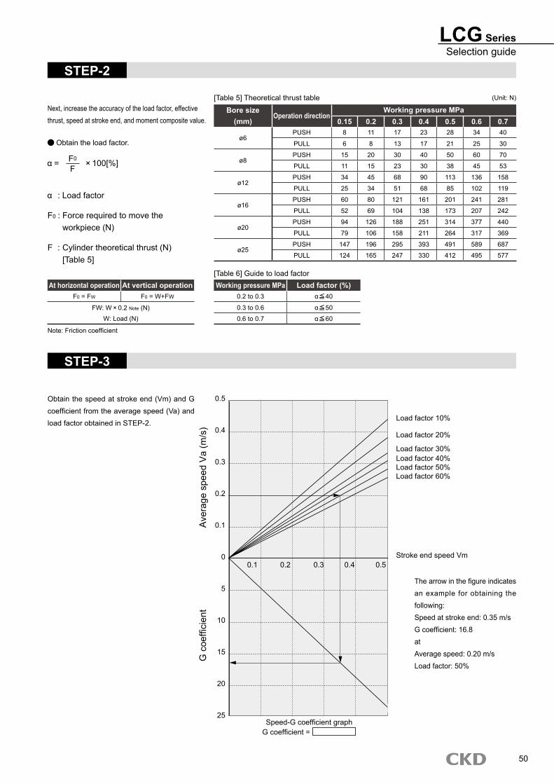
LCG SeriesSelection guide
STEP-2
Next, increase the accuracy of the load factor, effective thrust, speed at stroke end, and moment composite value.
At horizontal operation At vertical operationF0 = FW F0 = W+FW
FW: W 0.2 Note (N)W: Load (N)
[Table 5] Theoretical thrust table (Unit: N)
Bore sizeOperation direction
Working pressure MPa(mm) 0.15 0.2 0.3 0.4 0.5 0.6 0.7
ø6PUSH 8 11 17 23 28 34 40
PULL 6 8 13 17 21 25 30
ø8PUSH 15 20 30 40 50 60 70
PULL 11 15 23 30 38 45 53
ø12PUSH 34 45 68 90 113 136 158
PULL 25 34 51 68 85 102 119
ø16PUSH 60 80 121 161 201 241 281
PULL 52 69 104 138 173 207 242
ø20PUSH 94 126 188 251 314 377 440
PULL 79 106 158 211 264 317 369
ø25PUSH 147 196 295 393 491 589 687
PULL 124 165 247 330 412 495 577
Obtain the load factor.
= F0
F 100[%]
: Load factor
F0 : Force required to move the workpiece (N)
F : Cylinder theoretical thrust (N) [Table 5]
Note: Friction coefficient
Working pressure MPa Load factor (%)0.2 to 0.3 40
0.3 to 0.6 50
0.6 to 0.7 60
[Table 6] Guide to load factor
STEP-3
Obtain the speed at stroke end (Vm) and G coefficient from the average speed (Va) and load factor obtained in STEP-2.
The arrow in the figure indicates an example for obtaining the following:Speed at stroke end: 0.35 m/sG coefficient: 16.8atAverage speed: 0.20 m/sLoad factor: 50%
50
Ave
rage
spe
ed V
a (m
/s)
G c
oeffi
cien
t
0.5
0.4
0.3
0.2
0.1
0
5
10
15
20
25
0.1 0.2 0.3 0.4 0.5
Speed-G coefficient graphG coefficient =
Load factor 10%
Load factor 20%
Load factor 30%Load factor 40%Load factor 50%Load factor 60%
Stroke end speed Vm
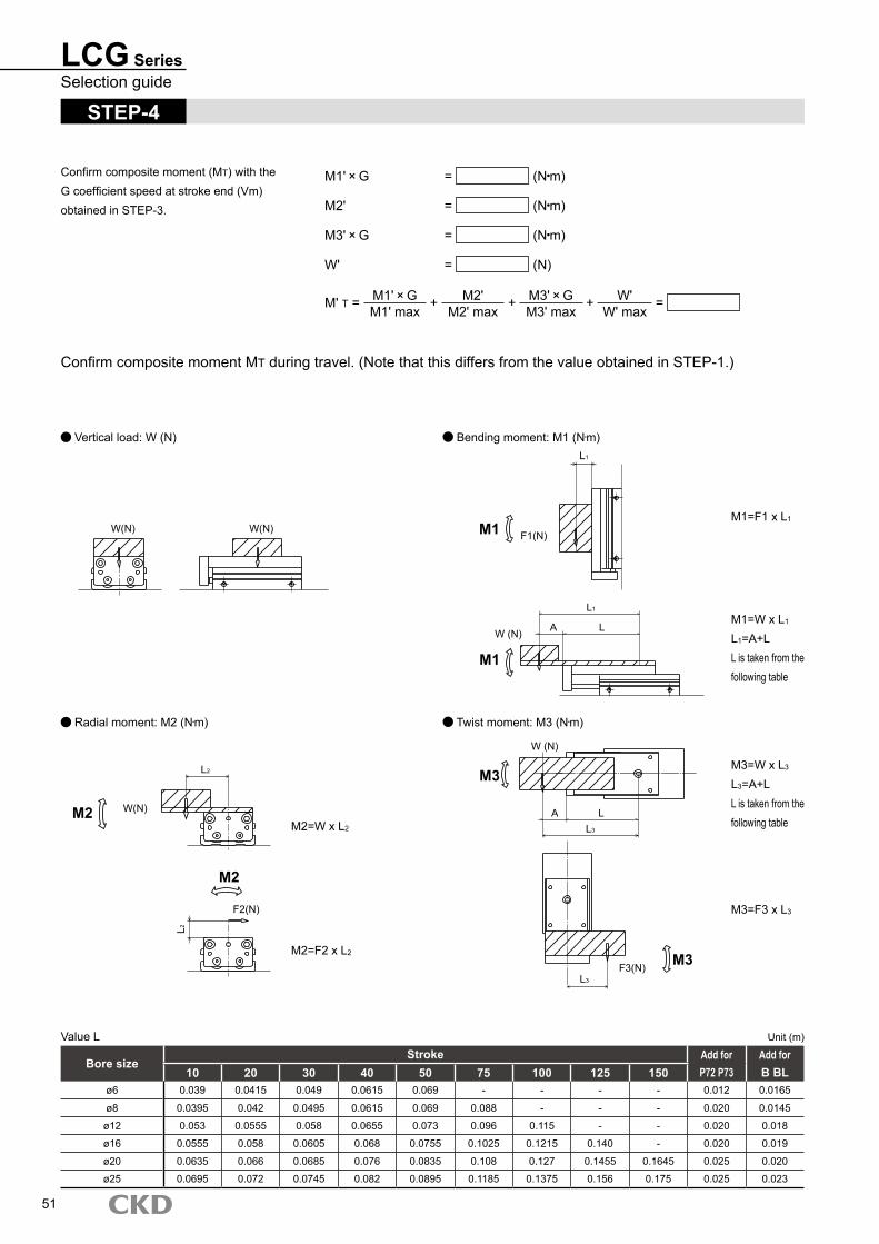
LCG SeriesSelection guide
STEP-4
Confirm composite moment (MT) with the G coefficient speed at stroke end (Vm) obtained in STEP-3.
M1' G = (N m)
M2' = (N m)
M3' G = (N m)
W' = (N)
M' T = M1' GM1' max
+ M2' M2' max
+ M3' GM3' max
+ W' W' max
=
Confirm composite moment MT during travel. (Note that this differs from the value obtained in STEP-1.)
Vertical load: W (N) Bending moment: M1 (Nm)
Radial moment: M2 (Nm) Twist moment: M3 (Nm)
Value L Unit (m)
51
Bore sizeStroke Add for Add for
10 20 30 40 50 75 100 125 150 P72 P73 B BLø6 0.039 0.0415 0.049 0.0615 0.069 - - - - 0.012 0.0165
ø8 0.0395 0.042 0.0495 0.0615 0.069 0.088 - - - 0.020 0.0145
ø12 0.053 0.0555 0.058 0.0655 0.073 0.096 0.115 - - 0.020 0.018
ø16 0.0555 0.058 0.0605 0.068 0.0755 0.1025 0.1215 0.140 - 0.020 0.019
ø20 0.0635 0.066 0.0685 0.076 0.0835 0.108 0.127 0.1455 0.1645 0.025 0.020
ø25 0.0695 0.072 0.0745 0.082 0.0895 0.1185 0.1375 0.156 0.175 0.025 0.023
W(N) W(N)
W(N)
L2
L2
F2(N)
M2
M2
L1
M1 F1(N)
L1
LAW (N)
M1
M3
W (N)
LAL3
M3F3(N)L3
M2=W x L2
M2=F2 x L2
M1=F1 x L1
M1=W x L1
L1=A+LL is taken from the following table
M3=W x L3
L3=A+LL is taken from the following table
M3=F3 x L3
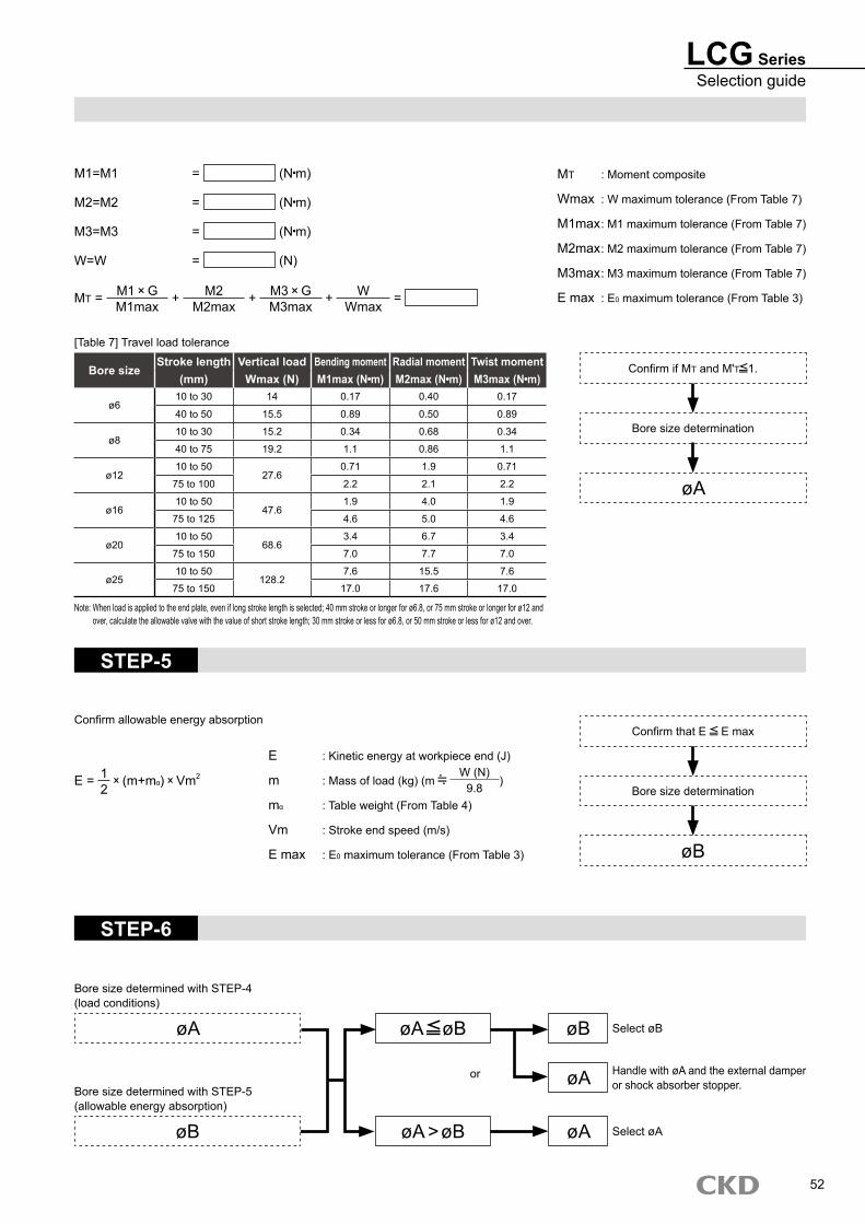
LCG SeriesSelection guide
M1=M1 = (N m)
M2=M2 = (N m)
M3=M3 = (N m)
W=W = (N)
MT = M1 GM1max
+ M2M2max
+ M3 GM3max
+ WWmax
=
MT : Moment composite
Wmax : W maximum tolerance (From Table 7)
M1max : M1 maximum tolerance (From Table 7)
M2max : M2 maximum tolerance (From Table 7)
M3max : M3 maximum tolerance (From Table 7)
E max : E0 maximum tolerance (From Table 3)
[Table 7] Travel load tolerance
Bore sizeStroke length Vertical load Bending moment Radial moment Twist moment
(mm) Wmax (N) M1max (N m) M2max (N m) M3max (N m)
ø610 to 30 14 0.17 0.40 0.17
40 to 50 15.5 0.89 0.50 0.89
ø810 to 30 15.2 0.34 0.68 0.34
40 to 75 19.2 1.1 0.86 1.1
ø1210 to 50
27.60.71 1.9 0.71
75 to 100 2.2 2.1 2.2
ø1610 to 50
47.61.9 4.0 1.9
75 to 125 4.6 5.0 4.6
ø2010 to 50
68.63.4 6.7 3.4
75 to 150 7.0 7.7 7.0
ø2510 to 50
128.27.6 15.5 7.6
75 to 150 17.0 17.6 17.0
Confirm if MT and M'T 1.
Bore size determination
øA
STEP-5
Confirm allowable energy absorption
E = 12
(m+m ) Vm2
E : Kinetic energy at workpiece end (J)
m : Mass of load (kg) (m W (N)
9.8 )
m : Table weight (From Table 4)
Vm : Stroke end speed (m/s)
E max : E0 maximum tolerance (From Table 3)
Confirm that E E max
Bore size determination
øB
STEP-6
Bore size determined with STEP-4 (load conditions)
øA
Bore size determined with STEP-5 (allowable energy absorption)
øB
øA øB
øA >øB
øB
øA
øAor
Select øB
Handle with øA and the external damper or shock absorber stopper.
Select øA
52
Note: When load is applied to the end plate, even if long stroke length is selected; 40 mm stroke or longer for ø6.8, or 75 mm stroke or longer for ø12 and over, calculate the allowable valve with the value of short stroke length; 30 mm stroke or less for ø6.8, or 50 mm stroke or less for ø12 and over.
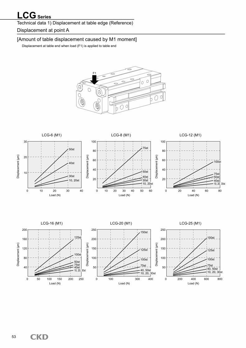
LCG SeriesTechnical data 1) Displacement at table edge (Reference)Displacement at point A
[Amount of table displacement caused by M1 moment]Displacement at table end when load (F1) is applied to table end
LCG-6 (M1) LCG-8 (M1) LCG-12 (M1)
LCG-16 (M1) LCG-20 (M1) LCG-25 (M1)
53
F1
Dis
plac
emen
t (m
)
30
20
10
0 10 20 30 40Load (N)
50st
40st
30st10, 20st
Dis
plac
emen
t (m
)
100
80
60
40
20
0 10 20 30 40 50 60Load (N)
75st
50st
40st30st10, 20st
Dis
plac
emen
t (m
)
Load (N)
100
80
60
40
20
0 20 40 60 80
100st
75st50st40st10, 20, 30st
Dis
plac
emen
t (m
)
80
0 50Load (N)
120
160
200
40
100 150 200 250
125st
100st
50st75st40st10, 20, 30st
Dis
plac
emen
t (m
)
0 100Load (N)
50
100
150
200
250
300 400
150st
125st
100st
75st40, 50st10, 20, 30st
Dis
plac
emen
t (m
)
0 200Load (N)
50
100
150
200
250
400 600 800
150st
125st
100st
75st40, 50st10, 20, 30st
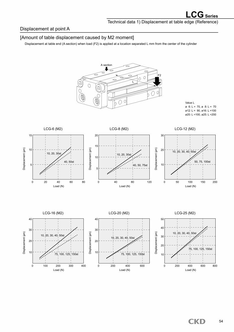
LCG-6 (M2) LCG-8 (M2) LCG-12 (M2)
LCG-16 (M2) LCG-20 (M2) LCG-25 (M2)
Displacement at point A
[Amount of table displacement caused by M2 moment]Displacement at table end (A section) when load (F2) is applied at a location separated L mm from the center of the cylinder
LCG SeriesTechnical data 1) Displacement at table edge (Reference)
Value Lø 6: L = 70, ø 8: L = 70ø12: L = 90, ø 16: L =100ø20: L =100, ø25: L =200
54
A section
F2
Dis
plac
emen
t (m
)
Load (N)
5
0
10
15
20 40 60 80
Dis
plac
emen
t (m
)
Load (N)
5
0
10
15
20
40 80 120
Dis
plac
emen
t (m
)
Load (N)
10
0
20
30
50 100 150 200
Dis
plac
emen
t (m
)
Load (N)
10
0
Dis
plac
emen
t (m
)
Load (N)
10
0
Dis
plac
emen
t (m
)
Load (N)
10
0
20
30
40
100 200 300 400
20
30
40
200 400 600
20
30
40
50
200 400 600 800
10, 20, 30st
40, 50st
10, 20, 30st
40, 50, 75st
10, 20, 30, 40, 50st
50, 75, 100st
10, 20, 30, 40, 50st
75, 100, 125, 150st
10, 20, 30, 40, 50st
75, 100, 125, 150st
10, 20, 30, 40, 50st
75, 100, 125, 150st
L
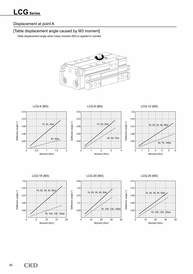
Displacement at point A
[Table displacement angle caused by M3 moment]Table displacement angle when rotary moment (M3) is applied to cylinder
LCG Series
LCG-6 (M3) LCG-8 (M3) LCG-12 (M3)
LCG-16 (M3) LCG-20 (M3) LCG-25 (M3)
55
M3
Defl
ectio
n an
gle
(°)
Moment (N m)0
0.003
0.006
0.009
0.012
0.015
0.5 1 1.5 2
Defl
ectio
n an
gle
(°)
Moment (N m)0
0.003
0.006
0.009
0.012
0.015
1 2 3 4
Defl
ectio
n an
gle
(°)
Moment (N m)0
0.004
0.008
0.012
0.016
0.02
1 2 3 4 5 6
Defl
ectio
n an
gle
(°)
Moment (N m)0
Defl
ectio
n an
gle
(°)
Moment (N m)
0.01
0
Defl
ectio
n an
gle
(°)
Moment (N m)0
0.004
0.008
0.012
0.016
0.02
5 10 15 20
0.015
0.02
0.025
10 20 30 40
0.003
0.006
0.009
0.012
0.015
10 20 30 40
10, 20, 30st
40, 50st
10, 20, 30, 40, 50st
50, 75, 100st
10, 20, 30st
40, 50, 75st
10, 20, 30, 40, 50st
75, 100, 125, 150st
10, 20, 30, 40, 50st
75, 100, 125, 150st
10, 20, 30, 40, 50st
75, 100, 125, 150st0.005
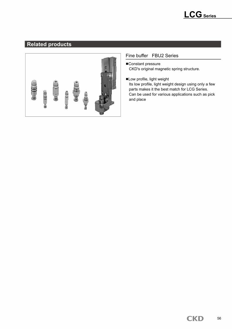
LCG Series
56
Related products
Fine buffer FBU2 Series■�Constant pressure CKD's original magnetic spring structure.
■�Low profile, light weight Its low profile, light weight design using only a few parts makes it the best match for LCG Series. Can be used for various applications such as pick and place

57
M E M OM E M O

M E M OM E M O
58