
High-Precision Vertical Machining Center for Die & Mold ...
12
NVD5000 α 1 HSC Machining Center HSC: High Speed Cutting High-Precision Vertical Machining Center for Die & Mold Manufacturers NVD5000 α 1 HSC
Transcript of High-Precision Vertical Machining Center for Die & Mold ...
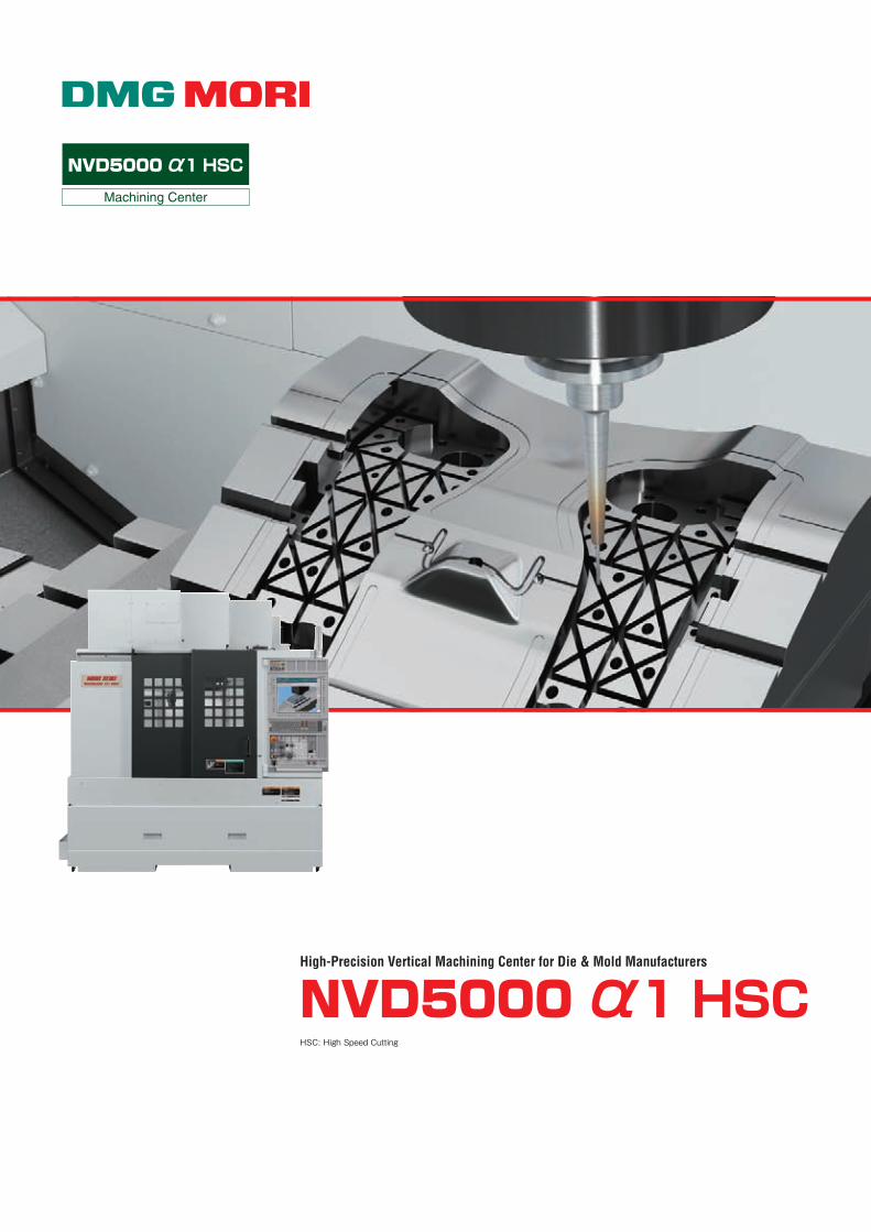
NVD5000 α1 HSC
Machining Center
HSC: High Speed Cutting
High-Precision Vertical Machining Center for Die & Mold Manufacturers
NVD5000 α1 HSC
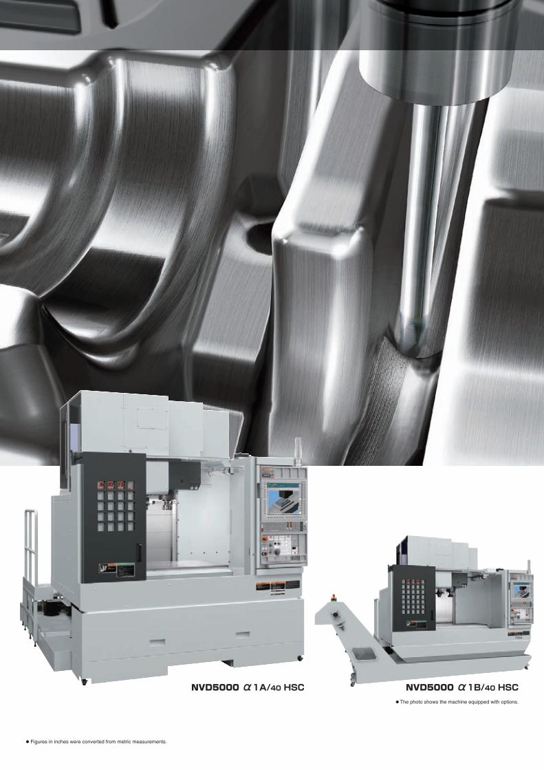
● Figures in inches were converted from metric measurements.
● The photo shows the machine equipped with options.
NVD5000 α1A/40 HSC NVD5000 α1B/40 HSC
CONTENTS
4
5
6
7
8
9
11
12
13
14
15
High precision
Die & Mold Specifications/Sample workpieces
Precision
Spindle
Improved workability
Peripheral equipment
MAPPS ⅣDiagrams
Standard & optional features
Numerical control unit specifications
Machine specifications
High-Precision Vertical Machining Center for Die & Mold Manufacturers
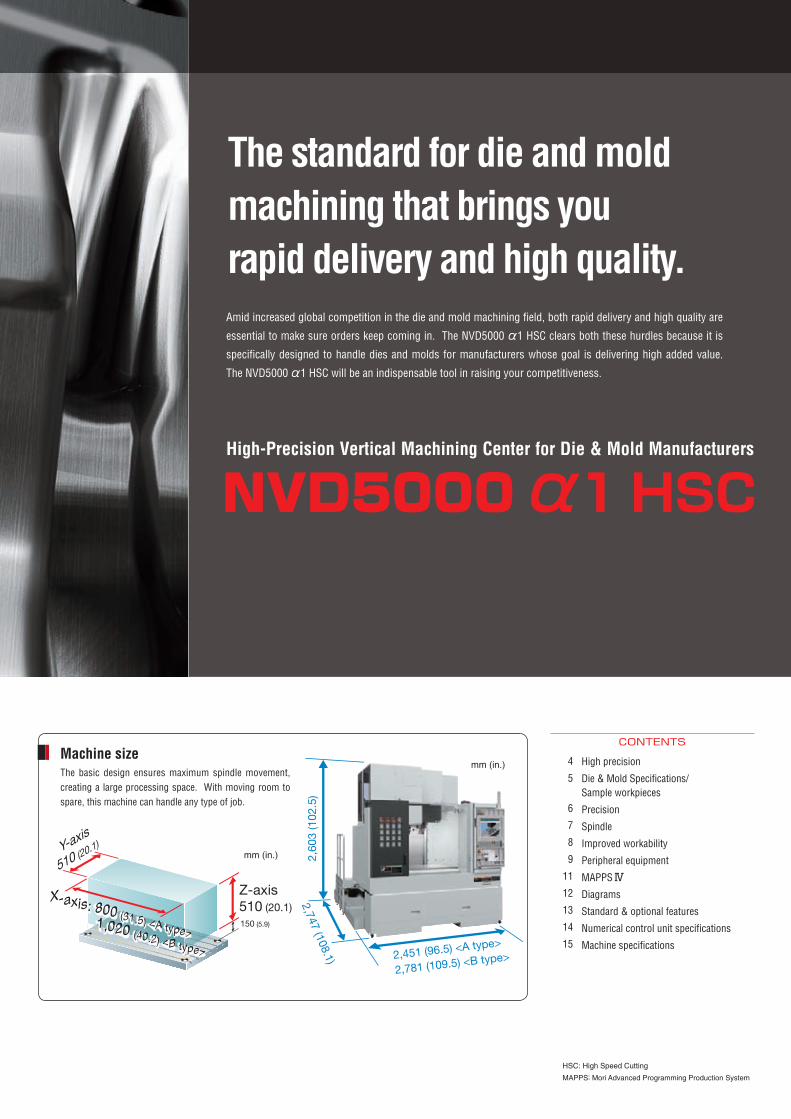
The basic design ensures maximum spindle movement, creating a large processing space. With moving room to spare, this machine can handle any type of job.
The standard for die and mold machining that brings yourapid delivery and high quality.
HSC: High Speed Cutting
MAPPS: Mori Advanced Programming Production System
Amid increased global competition in the die and mold machining field, both rapid delivery and high quality are
essential to make sure orders keep coming in. The NVD5000 α1 HSC clears both these hurdles because it is
specifically designed to handle dies and molds for manufacturers whose goal is delivering high added value.
The NVD5000 α1 HSC will be an indispensable tool in raising your competitiveness.
Machine size
2,451 (96.5) <A type>
2,781 (109.5) <B type>
2,747 (108.1)
2,60
3 (1
02.5
)
Y-axis
510 (20.1)
X-axis: 800 (31.5) <A type>
1,020 (40.2) <B type>
X-axis: 800 (31.5) <A type>
1,020 (40.2) <B type>
Z-axis 510 (20.1)150 (5.9)
mm (in.)
mm (in.)
NVD5000 α1 HSC
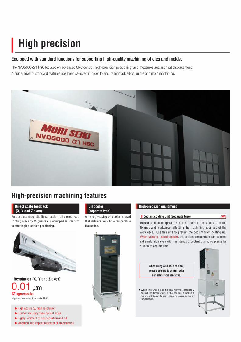
Equipped with standard functions for supporting high-quality machining of dies and molds.
The NVD5000 α1 HSC focuses on advanced CNC control, high-precision positioning, and measures against heat displacement.
A higher level of standard features has been selected in order to ensure high added-value die and mold machining.
High precision
High-precision machining features
An absolute magnetic linear scale (full closed-loop control) made by Magnescale is equipped as standard to offer high-precision positioning.
An energy-saving oil cooler is used that delivers very little temperature fluctuation.
Direct scale feedback (X, Y and Z axes)
Oil cooler (separate type)
High-precision equipment
■ Coolant cooling unit (separate type)
When using oil-based coolant, please be sure to consult with
our sales representative.
● While this unit is not the only way to completelycontrol the temperature of the coolant, it makes amajor contribution to preventing increases in the oiltemperature.
OP
Raised coolant temperature causes thermal displacement in the fixtures and workpiece, affecting the machining accuracy of the workpiece. Use this unit to prevent the coolant from heating up. When using oil-based coolant, the coolant temperature can become extremely high even with the standard coolant pump, so please be sure to select this unit.
High accuracy absolute scale SR87
0.01 μm■ Resolution (X, Y and Z axes)
● High accuracy, high resolution● Greater accuracy than optical scale ● Highly resistant to condensation and oil● Vibration and impact resistant characteristics
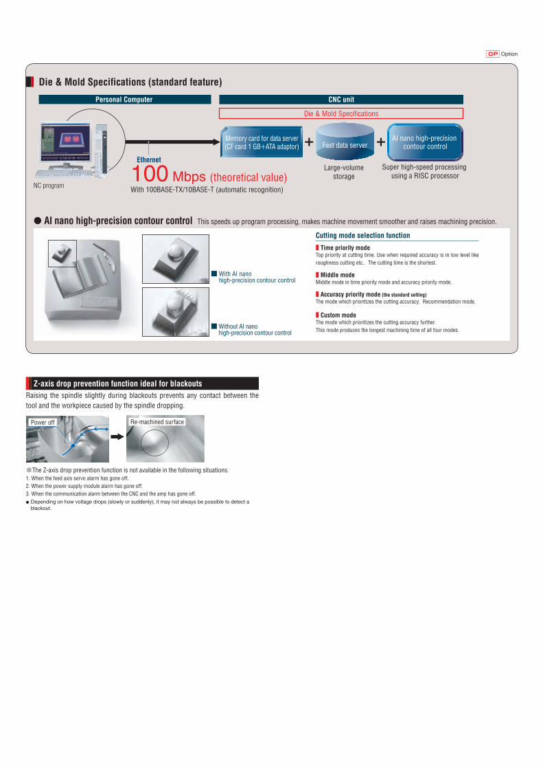
Re-machined surface
※The Z-axis drop prevention function is not available in the following situations.1. When the feed axis servo alarm has gone off.2. When the power supply module alarm has gone off.3. When the communication alarm between the CNC and the amp has gone off.● Depending on how voltage drops (slowly or suddenly), it may not always be possible to detect a
blackout.
Power off
Raising the spindle slightly during blackouts prevents any contact between the tool and the workpiece caused by the spindle dropping.
Z-axis drop prevention function ideal for blackouts
OptionOP
100 Mbps (theoretical value)With 100BASE-TX/10BASE-T (automatic recognition)
CNC unit
Die & Mold Specifications
EthernetLarge-volume
storageSuper high-speed processing
using a RISC processor
Fast data server
Personal Computer
AI nano high-precision contour control
Memory card for data server(CF card 1 GB+ATA adaptor)
Die & Mold Specifications (standard feature)
NC program
● AI nano high-precision contour control This speeds up program processing, makes machine movement smoother and raises machining precision.
Cutting mode selection function
■ Time priority modeTop priority at cutting time. Use when required accuracy is in low level like roughness cutting etc.. The cutting time is the shortest.
■ Middle modeMiddle mode in time priority mode and accuracy priority mode.
■ Accuracy priority mode (the standard setting)The mode which prioritizes the cutting accuracy. Recommendation mode.
■ Custom modeThe mode which prioritizes the cutting accuracy further.This mode produces the longest machining time of all four modes.
■ With AI nano high-precision contour control
■ Without AI nano high-precision contour control

Approximately 70% longerCompared with previous model
High-speed, high-power DDS motor.
Super high speeds are achieved with the stable supply of lubricant and the internal cooling effect of the air. It is further equipped with a long-life spindle bearing with greater wear-resistance and burn-resistance than previous models.
Oil-air lubrication
● �Oil feed is kept to a minimum to reducefrictional loss
●�Air purge prevents dust infiltration
DDS: Direct Drive Spindle
Spindle
Spindle bearing design
Spindle bearing roller life
■ BT40 (standard)
■ Spindle acceleration time ■ Spindle deceleration time
■ HSK-A63 (option)
High-speed spindle bearing
Dual contact specifications
Reduced by
50%Reduced by
53%
Spindle acceleration/deceleration time
● Please use a dual contact tool when cutting at 15,000 min-1 or higher.
Oil-air lubrication
Eco-friendly design
■ Automatic sleep function
■ Automatic machine light function
If the keyboard is not touched for a certain amount of time and NC operation is not being performed, power is cut off to the servo motor, the spindle, the coolant pump and the chip conveyor, thereby saving energy.
�If the operating panel is not touched for a certain amount of time, the interior light turns off. This saves energy and lengthens the life of the machine lights.
Energy-saving settings screen
Reduced consumption of lubricating oil Reduced consumption of electricity
■ Oil-bath ATC
An oil-bath design has been integrated into the ATC unit design. Compared with conventional oil drip designs, the amount of lubricating oil used has been radically reduced.
Previous model
5.32 sec.
Previous model
5.48 sec.2.68 sec. 2.56 sec.
Constrainedface
Constrainedface
NVD5000�α1�HSC NVD5000�α1�HSC
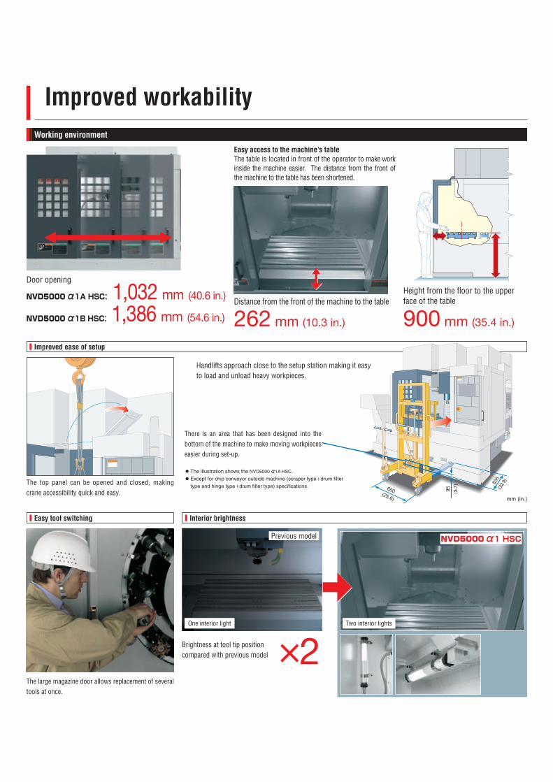
■ Improved ease of setup
The large magazine door allows replacement of several tools at once.
Previous model
The top panel can be opened and closed, making crane accessibility quick and easy.
One interior light Two interior lights
Brightness at tool tip position compared with previous model ×2
Easy access to the machine’s tableThe table is located in front of the operator to make work inside the machine easier. The distance from the front of the machine to the table has been shortened.
There is an area that has been designed into the bottom of the machine to make moving workpieces easier during set-up.
Improved workabilityWorking environment
■ Easy tool switching ■ Interior brightness
Height from the floor to the upper face of the table
900 mm (35.4 in.)
Distance from the front of the machine to the table
262 mm (10.3 in.)
NVD5000 α1A HSC: 1,032 mm (40.6 in.)
NVD5000 α1B HSC: 1,386 mm (54.6 in.)
● The illustration shows the NVD5000 α1A HSC.● Except for chip conveyor outside machine (scraper type+drum filter
type and hinge type+drum filter type) specifications.
Door opening
NVD5000�α1�HSC
650(25.6)
835
(32.
9)
95 (3.7
)
mm (in.)
Handlifts approach close to the setup station making it easy to load and unload heavy workpieces.
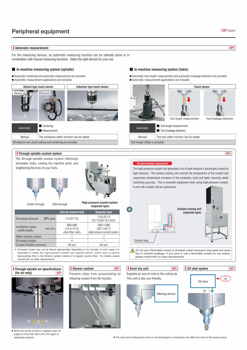
Prevents chips from accumulating by releasing coolant from the nozzles.
Supplies air and oil mist to the cutting tip. This unit is also eco-friendly.
Misting device
Peripheral equipment
■ Automatic measurement
For the measuring devices, an automatic measuring function can be selected alone or in combination with manual measuring functions. Select the right devices for your use.
■ In-machine measuring system (table)
● Automatic tool length measurement and automatic breakage detection are possible.● Automatic measurement applications are included.
■ In-machine measuring system (spindle)
● Automatic centering and automatic measurement are possible.● Automatic measurement applications are included.
OP
Optical type touch sensor Inductive type touch sensor Touch sensor
Tool length measurement Tool breakage detection
Sensor Receiver
● When the tool tip air blow is regularly used, air
supply of more than 300 L/min (79.2 gpm) is
separately required.
AirAir
Automatic■ Centering
■ MeasurementAutomatic
■ Tool length measurement
■ Tool breakage detection
Manual The workpiece setter function can be added
Workpiece zero point setting and centering are possible
Manual The tool setter function can be added
Tool length offset is possible
OptionOP
■ Shower coolant ■ Semi-dry unit ■ Oil shot system■ Through-spindle air specifications (for air only) OP
OPOPOP
エアオイルタンク
オイル
Oil tankAir
Oil
The high-pressure coolant unit generates a lot of heat because it discharges coolant at
high pressure. The coolant cooling unit controls the temperature of the coolant and
suppresses temperature increases in the workpiece, tools and table, ensuring stable
machining accuracy. This is essential equipment when using high-pressure coolant.
A unit with a heater will be customized.
Recommended equipment
+ Coolant cooling unit (separate type)
■ Through-spindle coolant system
Coolant tank
OP
The through-spindle coolant system effectively eliminates chips, cooling the machine point, and lengthening the lives of your tools.
Unit on coolant tank Separate type
Discharge pressure�� MPa (psi) 1.5 (217.5) 1.5/3.5/7.0(217.5/507.5/1,015)
Installation space <width×depth> mm (in.)
360×360(14.2×14.2)
<line filter unit>
780×1,085(30.7×42.7)
<high-pressure coolant system>Water-soluble coolant ○ ○Oil-based coolant × ○*
Coolant filtration accuracy 40 μm 20 μm* Oil-based coolant may not be filtered appropriately depending on its viscosity. In such cases it is
advisable to select the high-pressure coolant unit (special option), which uses a ceramic backwashing filter in the filtration system instead of a regular cyclone filter. For details, please consult with our sales representative.
High-pressure coolant system (separate type)
Center through Side through
● The colors and configurations shown in the photographs or illustrations may differ from those of the actual product.
Do not use a flammable coolant or oil-based coolant because it may ignite and cause fire or machine breakage. If you have to use a flammable coolant for any reason, please consult with our sales representative.
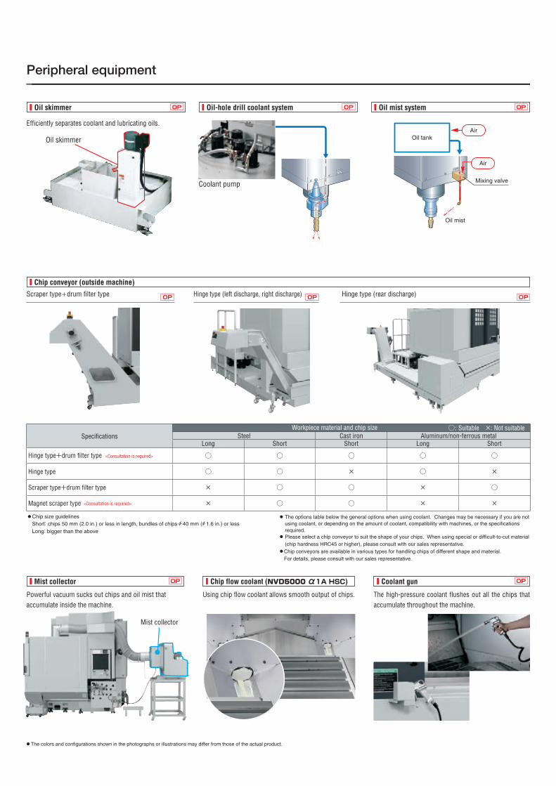
Coolant pump
Oil skimmer
■ Oil skimmer ■ Oil-hole drill coolant system ■ Oil mist systemOP OP OP
Powerful vacuum sucks out chips and oil mist that accumulate inside the machine.
The high-pressure coolant flushes out all the chips that accumulate throughout the machine.
Using chip flow coolant allows smooth output of chips.
Mist collector
■ Chip conveyor (outside machine)
■ Mist collector ■ Chip flow coolant (NVD5000 α1A HSC)
Scraper type+drum filter type Hinge type (left discharge, right discharge) Hinge type (rear discharge)
■ Coolant gun
OPOPOP
OP OP
SpecificationsWorkpiece material and chip size ○: Suitable ×: Not suitable
Steel Cast iron Aluminum/non-ferrous metalLong Short Short Long Short
Hinge type+drum filter type ○ ○ ○ ○ ○
Hinge type ○ ○ × ○ ×
Scraper type+drum filter type × ○ ○ × ○
Magnet scraper type × ○ ○ × ×
● Chip size guidelines Short: chips 50 mm (2.0 in.) or less in length, bundles of chips A 40 mm (A 1.6 in.) or lessLong: bigger than the above
● The options table below the general options when using coolant. Changes may be necessary if you are not using coolant, or depending on the amount of coolant, compatibility with machines, or the specifications required.
● Please select a chip conveyor to suit the shape of your chips. When using special or difficult-to-cut material (chip hardness HRC45 or higher), please consult with our sales representative.
● Chip conveyors are available in various types for handling chips of different shape and material.For details, please consult with our sales representative.
Peripheral equipment
Mixing valve
Oil tank
Oil mist
Air
Air
Efficiently separates coolant and lubricating oils.
<Consultation is required>
<Consultation is required>
● The colors and configurations shown in the photographs or illustrations may differ from those of the actual product.
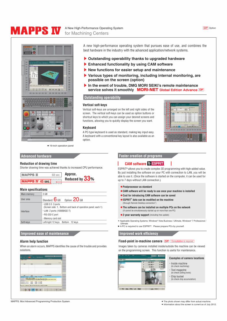
OptionOPA New High-Performance Operating System
for Machining Centers
● 19-inch operation panel
MAPPS: Mori Advanced Programming Production System ● The photo shown may differ from actual machine.● Information about the screen is current as of July 2012.
Reduction of drawing time
Main specifications
Shorter drawing time was achieved thanks to increased CPU performance.
Main memory 3 GB
User area Standard: 6 GB Option: 20 GB
Interface
・ USB 2.0 3 ports(Screen side: 1, Bottom and back of operation panel: each 1)
・LAN 2 ports (1000BASE-T)
・RS-232-C port
・Memory card slot
Soft-keys Left/right 12 keys Bottom 12 keys
Advanced hardware
Approx. Reduced by 33%
68 sec.
45 sec.MAPPS Ⅳ
MAPPS Ⅲ
Faster creation of programs
* Applicable Operating Systems: Windows® Vista Business / Ultimate, Windows® 7 Professional / Ultimate
● A PC is required to use ESPRIT®. Please prepare PCs by yourself.
ESPRIT® allows you to create complex 3D programming with high-added value. By just installing the software on your PC with connection to LAN, you will be able to use it. (Once the software is started on the computer, it can be used for up to 7 days without LAN connection.)
⃝Postprocessor as standard
⃝CAM software will be ready to use once your machine is installed
⃝Cost for introducing CAM software can be saved
⃝ ESPRIT® data can be modifi ed on the machine (through Remote Desktop connection*)
⃝�The software can be installed on multiple PCs on the network (It cannot be simultaneously started up on more than one PC)
⃝2-year warranty support (including free update)
CAM software
A new high-performance operating system that pursues ease of use, and combines the best hardware in the industry with the advanced application/network systems.
Vertical soft-keys
Keyboard
Vertical soft-keys are arranged on the left and right sides of the screen. The vertical soft-keys can be used as option buttons or shortcut keys to which you can assign your desired screens and functions, allowing you to quickly display the screen you want.
A PC-type keyboard is used as standard, making key input easy. A keyboard with a conventional key layout is also available as an option.
Outstanding operability
▶ Outstanding operability thanks to upgraded hardware▶ Enhanced functionality by using CAM software▶ New functions for easier setup and maintenance▶ Various types of monitoring, including internal monitoring, are
possible on the screen (option)▶ In the event of trouble, DMG MORI SEIKI’s remote maintenance
service solves it smoothly MORI-NET Global Edition Advance OP
Alarm help functionWhen an alarm occurs, MAPPS identifi es the cause of the trouble and provides solutions.
Improved ease of maintenance Improved work effi ciency
Examples of camera locations
・ Inside machine (to check machining)
・ Tool magazine (to check cutting tools)
・ Chip bucket (to check chip accumulation)
Fixed-point in-machine cameraImages taken by cameras installed inside/outside the machine can be viewedon the programming screen. This function is useful for maintenance.
Consultation is requiredOP
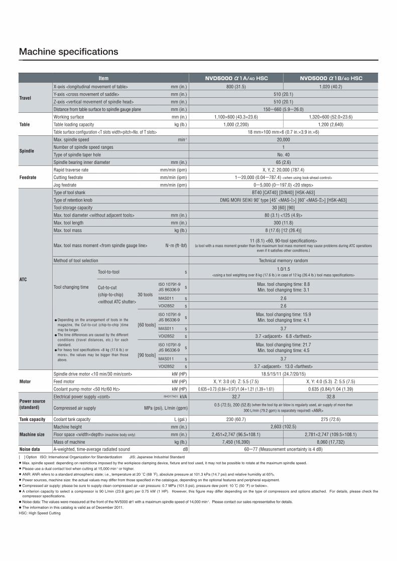
Machine specifications
Item NVD5000 α1A/40 HSC NVD5000 α1B/40 HSC
Travel
X-axis <longitudinal movement of table> mm (in.) 800 (31.5) 1,020 (40.2)
Y-axis <cross movement of saddle> mm (in.) 510 (20.1)
Z-axis <vertical movement of spindle head> mm (in.) 510 (20.1)
Distance from table surface to spindle gauge plane mm (in.) 150−660 (5.9−26.0)
Table
Working surface mm (in.) 1,100×600 (43.3×23.6) 1,320×600 (52.0×23.6)
Table loading capacity kg (lb.) 1,000 (2,200) 1,200 (2,640)
Table surface configuration <T slots width×pitch×No. of T slots> 18 mm×100 mm×6 (0.7 in.×3.9 in.×6)
Spindle
Max. spindle speed min-1 20,000
Number of spindle speed ranges 1
Type of spindle taper hole No. 40
Spindle bearing inner diameter mm (in.) 65 (2.6)
Feedrate
Rapid traverse rate mm/min (ipm) X, Y, Z: 20,000 (787.4)
Cutting feedrate mm/min (ipm) 1−20,000 (0.04−787.4) <when using look-ahead control>
Jog feedrate mm/min (ipm) 0−5,000 (0−197.0) <20 steps>
ATC
Type of tool shank BT40 [CAT40] [DIN40] [HSK-A63]
Type of retention knob DMG MORI SEIKI 90˚ type [45˚ <MAS-Ⅰ>] [60˚ <MAS-Ⅱ>] [HSK-A63]
Tool storage capacity 30 [60] [90]
Max. tool diameter <without adjacent tools> mm (in.) 80 (3.1) <125 (4.9)>
Max. tool length mm (in.) 300 (11.8)
Max. tool mass kg (lb.) 8 (17.6) [12 (26.4)]
Max. tool mass moment <from spindle gauge line> N・m (ft・lbf)11 (8.1) <60, 90-tool specifications>
{a tool with a mass moment greater than the maximum tool mass moment may cause problems during ATC�operations even if it satisfies other conditions.}
Method of tool selection Technical memory random
Tool changing time
Tool-to-tool s 1.0/1.5<using a tool weighting over 8 kg (17.6 lb.) in case of 12 kg (26.4 lb.) tool mass specifications>
Cut-to-cut(chip-to-chip)<without ATC shutter>
30 tools
ISO 10791-9JIS B6336-9 s Max. tool changing time: 8.8
Min. tool changing time: 3.1
MAS011 s 2.6
VDI2852 s 2.6
● Depending on the arrangement of tools in themagazine, the Cut-to-cut (chip-to-chip )timemay be longer.
● The time differences are caused by the different conditions (travel distances, etc.) for eachstandard.
● For heavy tool specifications <8 kg (17.6 lb.) or more>, the values may be bigger than thoseabove.
[60 tools]
ISO 10791-9JIS B6336-9 s Max. tool changing time: 15.9
Min. tool changing time: 4.1
MAS011 s 3.7
VDI2852 s 3.7 <adjacent> 6.8 <farthest>
[90 tools]
ISO 10791-9JIS B6336-9 s Max. tool changing time: 21.7
Min. tool changing time: 4.5
MAS011 s 3.7
VDI2852 s 3.7 <adjacent> 13.0 <farthest>
Motor
Spindle drive motor <10 min/30 min/cont> kW (HP) 18.5/15/11 (24.7/20/15)
Feed motor kW (HP) X, Y: 3.0 (4) Z: 5.5 (7.5) X, Y: 4.0 (5.3) Z: 5.5 (7.5)
Coolant pump motor <50 Hz/60 Hz> kW (HP) 0.635+0.73 (0.84+0.97)/1.04+1.21 (1.39+1.61) 0.635 (0.84)/1.04 (1.39)
Power source(standard)
Electrical power supply <cont> I94317A01 kVA 32.7 32.8
Compressed air supply MPa (psi), L/min (gpm)0.5 (72.5), 200 (52.8) {when the tool tip air blow is regularly used, air supply of more than
300 L/min (79.2 gpm) is separately required} <ANR>
Tank capacity Coolant tank capacity L (gal.) 230 (60.7) 275 (72.6)
Machine size
Machine height mm (in.) 2,603 (102.5)
Floor space <width×depth> {machine body only} mm (in.) 2,451×2,747 (96.5×108.1) 2,781×2,747 (109.5×108.1)
Mass of machine kg (lb.) 7,450 (16,390) 8,060 (17,732)Noise data A-weighted, time-average radiated sound dB 60ー77 (Measurement uncertainty is 4 dB)
[ ] Option ISO: International Organization for Standardization JIS: Japanese Industrial Standard X Max. spindle speed: depending on restrictions imposed by the workpiece clamping device, fixture and tool used, it may not be possible to rotate at the maximum spindle speed.
X Please use a dual contact tool when cutting at 15,000 min-1 or higher.
X ANR: ANR refers to a standard atmospheric state; i.e., temperature at 20 ˚C (68 ˚F), absolute pressure at 101.3 kPa (14.7 psi) and relative humidity at 65%.
X Power sources, machine size: the actual values may differ from those specified in the catalogue, depending on the optional features and peripheral equipment. ● Compressed air supply: please be sure to supply clean compressed air <air pressure: 0.7 MPa (101.5 psi), pressure dew point: 10 ℃ (50 ˚F) or below>.● A criterion capacity to select a compressor is 90 L/min (23.8 gpm) per 0.75 kW (1 HP). However, this figure may differ depending on the type of compressors and options attached. For details, please check the
compressor specifications.
● Noise data: The values were measured at the front of the NV5000 α1 with a maximum spindle speed of 14,000 min-1. Please contact our sales representative for details.● The information in this catalog is valid as of December 2011.
HSC: High Speed Cutting

EXPORTATION: All contracts are subject to export permit by the Government of Japan. Customer shall comply with the laws and regulations of the exporting country governing the exportation or re-exportation of the Equipment, including but not limited to the Export Administration Regulations. The Equipment is subject to export restrictions imposed by Japan and other exporting countries and the Customer will not export or permit the export of the Equipment anywhere outside the exporting country without proper government authorization. To prevent the illegal diversion of the Equipment to individuals or nations that threaten international security, it may include a “Relocation Machine Security Function” that automatically disables the Equipment if it is moved following installation. If the Equipment is so-disabled, it can only be re-enabled by contacting DMG MORI SEIKI or its distributor representative. DMG MORI SEIKI and its distributor representative may refuse to re-enable the Equipment if it determines that doing so would be an unauthorized export of technology or otherwise violates applicable export restrictions. DMG MORI SEIKI and its distributor representative shall have no obligation to re-enable such Equipment. DMG MORI SEIKI and its distributor representative shall have no liability (including for lost profits or business interruption or under the limited service warranty included herein) as a result of the Equipment being disabled.
<Precautions for Machine Relocation>
● DCG, DDM, BMT and ORC are trademarks or registered trademarks of DMG MORI SEIKI CO., LTD. in Japan, the USA and other countries.● If you have any questions regarding the content, contact our sales representative.● The information in this catalog is valid as of October 2013. Designs and specifications are subject to changes without notice.● The machines shown in the catalog may differ from the actual machines. The location and the size of the nameplates may also differ from the actual machines, or the nameplates may not be
attached to some machines.● DMG MORI SEIKI is not responsible for differences between the information in the catalog and the actual machine.
NVD5000a1-EE02ABD(N)
D.1310.CDT.0000
Created in Japan
2-year warranty, twice the peace of mind. For machines delivered outside of Japan, parts relating to machine breakdown will be guaranteed free for 2 years from the date of installation, and labor costs to repair will be free for 1 year. Please contact our sales representative for details.
Nagoya Head Office □ 2-35-16 Meieki, Nakamura-ku, Nagoya City, Aichi 450-0002, Japan Phone: +81-52-587-1811
Tokyo Branch □ 18th floor, Shinagawa Intercity Tower A, 2-15-1 Konan Minato-ku, Tokyo 108-6018, Japan Phone: +81-3-5460-3570Nara Campus Nara No. 1 Plant □ 362 Idono-cho, Yamato-Koriyama City, Nara 639-1183, Japan Phone: +81-743-53-1121
Nara No. 2 Plant □ 106 Kita-Koriyama-cho, Yamato-Koriyama City, Nara 639-1160, Japan Phone: +81-743-53-1125Iga Campus □ 201 Midai, Iga City, Mie 519-1414, Japan Phone: +81-595-45-4151Chiba Campus □ 488-19 Suzumi-cho, Funabashi City, Chiba 274-0052, Japan Phone: +81-47-410-8800
DMG MORI SEIKI CO., LTD.