High Photo-Current in Solution Processed Organic Solar ...
41
Page 1 of 41 High Photo-Current in Solution Processed Organic Solar Cells Based on Porphyrin Core A-π-D-π-A as Electron Donor Material Núria F. Montcada, a Susana Arrechea, b Agustín Molina-Ontoria, c Ana I. Aljarilla, b Pilar de la Cruz, b Luis Echegoyen, *c Emilio Palomares *a,d and Fernando Langa *b a Institute of Chemical Research of Catalonia (ICIQ), The Barcelona Institute of Science and Technology. Avda. Països Catalans, 16. Tarragona. E-43007. Spain. E-mail: [email protected] b Universidad de Castilla-La Mancha, Institute of Nanoscience, Nanotechnology and Molecular Materials (INAMOL), Campus de la Fábrica de Armas, Toledo, Spain. Tel: 34 9252 68843. E-mail: [email protected] c Department of Chemistry, University of Texas at El Paso, El Paso, TX 79968, USA. Tel: 915-747-7573. E-mail: [email protected] d ICREA, Passeig Lluis Companys 23, Barcelona E-08010, Spain. *Manuscript Click here to view linked References
Transcript of High Photo-Current in Solution Processed Organic Solar ...

Page 1 of 41
High Photo-Current in Solution Processed Organic
Solar Cells Based on Porphyrin Core A-π-D-π-A as
Electron Donor Material
Núria F. Montcada,a Susana Arrechea,
b Agustín Molina-Ontoria,
c Ana I. Aljarilla,
b Pilar de la
Cruz,b Luis Echegoyen,
*c Emilio Palomares
*a,d and Fernando Langa
*b
a Institute of Chemical Research of Catalonia (ICIQ), The Barcelona Institute of Science and
Technology. Avda. Països Catalans, 16. Tarragona. E-43007. Spain. E-mail:
b Universidad de Castilla-La Mancha, Institute of Nanoscience, Nanotechnology and
Molecular Materials (INAMOL), Campus de la Fábrica de Armas, Toledo, Spain. Tel: 34
9252 68843. E-mail: [email protected]
c Department of Chemistry, University of Texas at El Paso, El Paso, TX 79968, USA. Tel:
915-747-7573. E-mail: [email protected]
d ICREA, Passeig Lluis Companys 23, Barcelona E-08010, Spain.
*ManuscriptClick here to view linked References
Page 2 of 41
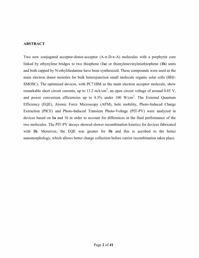
ABSTRACT
Two new conjugated acceptor-donor-acceptor (A--D--A) molecules with a porphyrin core
linked by ethynylene bridges to two thiophene (1a) or thienylenevinylenethiophene (1b) units
and both capped by N-ethylrhodanine have been synthesized. These compounds were used as the
main electron donor moieties for bulk heterojunction small molecule organic solar cells (BHJ-
SMOSC). The optimized devices, with PC71BM as the main electron acceptor molecule, show
remarkable short circuit currents, up to 13.2 mA/cm2, an open circuit voltage of around 0.85 V,
and power conversion efficiencies up to 4.3% under 100 W/cm2. The External Quantum
Efficiency (EQE), Atomic Force Microscopy (AFM), hole mobility, Photo-Induced Charge
Extraction (PICE) and Photo-Induced Transient Photo-Voltage (PIT-PV) were analyzed in
devices based on 1a and 1b in order to account for differences in the final performance of the
two molecules. The PIT-PV decays showed slower recombination kinetics for devices fabricated
with 1b. Moreover, the EQE was greater for 1b and this is ascribed to the better
nanomorphology, which allows better charge collection before carrier recombination takes place.
Page 3 of 41
1. Introduction
Solution processed organic solar cells (OSCs) have improved significantly in recent decades,[1-
4] due to the judicious design of push-pull low band-gap copolymers, optimization of the
nanoscale morphologies of the photoactive layers and enhanced carrier mobility, all of which
have led to power conversion efficiencies (PCEs) of 10% for single-junction polymer solar cells
(PSCs)[5, 6] and up to 11% for tandem PSCs.[7] Moreover, small molecule organic solar cells
(SMOSCs) have emerged as complementary systems to the polymeric materials and they have
undergone rapid development in recent years as SMOSCs offer potential advantages such as the
possibility of obtaining better-defined molecular structures, easier purification and better batch-
to-batch reproducibility.[8, 9] Indeed, power conversion efficiencies for bulk heterojunction
small molecule organic solar cells (BHJ-SMOSCs) have exceeded 10% and these are expected to
be higher for tandem devices.[10-13]
Numerous different chemical architectures, especially as donor moieties, have been explored for
SMOSCs [11, 14-19] and the most promising are the donor-acceptor (D-A) ‘push-pull’
molecules. Within this group, the use of porphyrin moieties (POR) as the main donor has
recently been reported but this remains relatively unexplored.
Inspired by natural photosynthetic structures, such us chlorophylls, porphyrins and their
derivatives, these excellent building blocks offer efficient light harvesting architectures, high
stability, and their large and rigid planar structure allows fine tuning of their energetic and
morphological properties.[20] For example, POR-based photosensitizers are among the best
sensitizers in dye sensitized solar cells (DSSCs). In recent years, remarkable progress has been
made on using POR as the main donor moieties[21-26] and efficiencies as high as 8% have been
Page 4 of 41
reached in SMOSC [27] devices while in DSSC systems efficiencies close to 12% have been
described.[28]
Recently, we described two similar conjugated acceptor-donor-acceptor (A--D--A)
compounds that also contained a Zn-porphyrin but were capped by dicyanovinylene groups as
acceptor units – these materials gave a photoconversion efficiency (PCE) of 3.21%.[29] With the
aim of significantly improving the design and thus the performance of the final device, we report
here: (a) the synthesis and characterization of two new conjugated POR-based acceptor-donor-
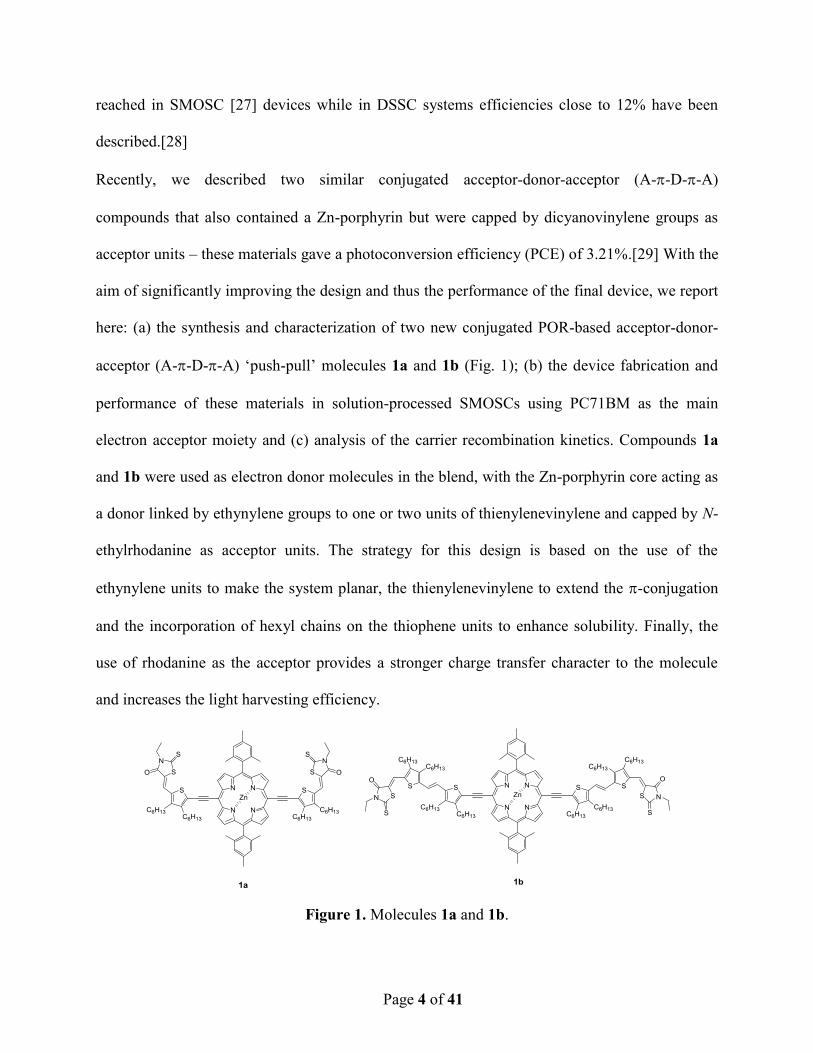
acceptor (A--D--A) ‘push-pull’ molecules 1a and 1b (Fig. 1); (b) the device fabrication and
performance of these materials in solution-processed SMOSCs using PC71BM as the main
electron acceptor moiety and (c) analysis of the carrier recombination kinetics. Compounds 1a
and 1b were used as electron donor molecules in the blend, with the Zn-porphyrin core acting as
a donor linked by ethynylene groups to one or two units of thienylenevinylene and capped by N-
ethylrhodanine as acceptor units. The strategy for this design is based on the use of the
ethynylene units to make the system planar, the thienylenevinylene to extend the -conjugation
and the incorporation of hexyl chains on the thiophene units to enhance solubility. Finally, the
use of rhodanine as the acceptor provides a stronger charge transfer character to the molecule
and increases the light harvesting efficiency.
Figure 1. Molecules 1a and 1b.
Page 5 of 41
Synthesis and Characterization
Compounds 1a-b were obtained in 82% and 45% yield, respectively, by Knoevenagel
condensation of 2a-b[28] with N-ethylrhodanine and piperidine as base (Scheme 1). Both new
compounds were satisfactorily characterized by 1H and
13C NMR, FT-IR and MALDI-MS (see
Supporting Information for synthetic details and full analytical and spectroscopic data). In the 1H
NMR spectra of 1a and 1b a new signal was observed at 8.00 ppm and 7.95 ppm, respectively,
and this confirms the success of the condensation reaction. The mass spectrum of 1a showed the
molecular ion peak at m/z 1498.75 amu and 1b gave a molecular ion peak at m/z 2051.69 amu.
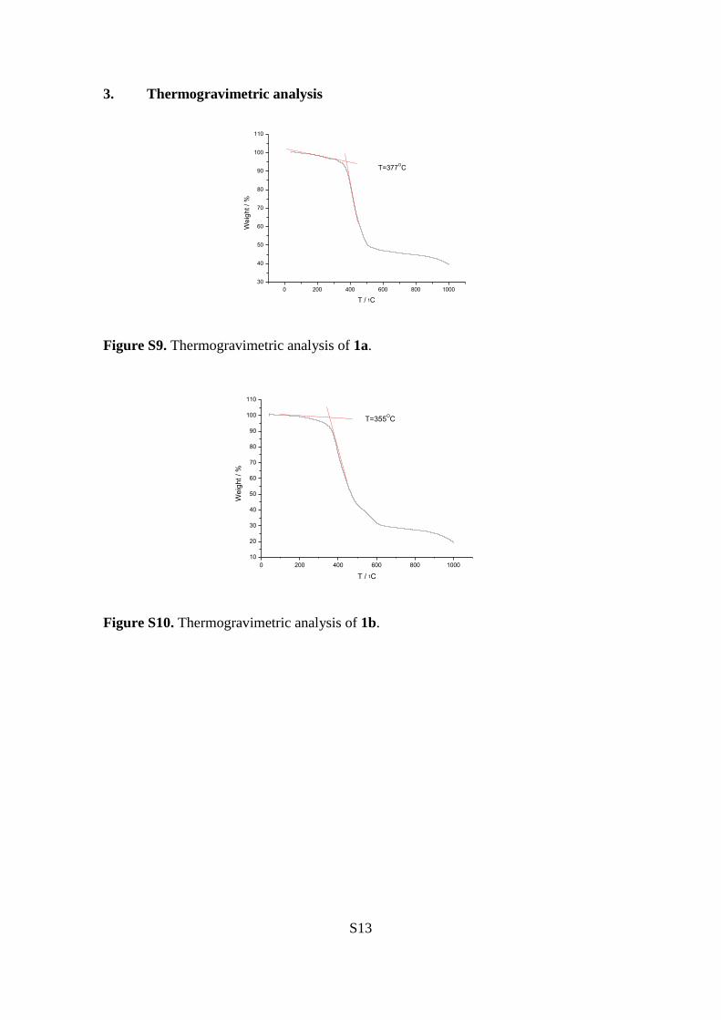
Compounds 1a-b showed excellent thermal stability up to 300 °C, with Td values of 377 °C and
355 °C for 1a and 1b, respectively (Figure S9 and S10); this thermal stability is suitable for
photovoltaic applications.
Optical Properties
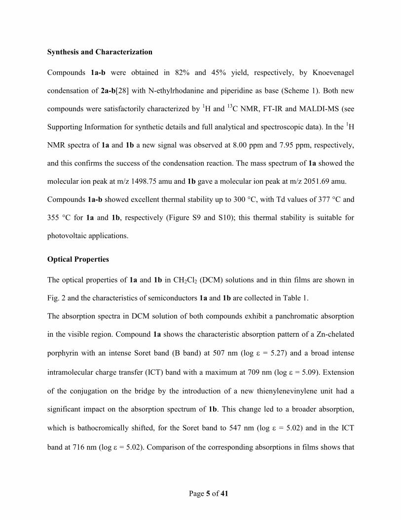
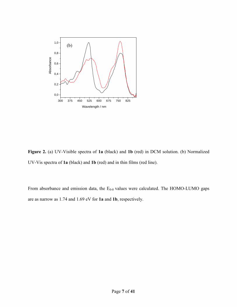
The optical properties of 1a and 1b in CH2Cl2 (DCM) solutions and in thin films are shown in
Fig. 2 and the characteristics of semiconductors 1a and 1b are collected in Table 1.
The absorption spectra in DCM solution of both compounds exhibit a panchromatic absorption
in the visible region. Compound 1a shows the characteristic absorption pattern of a Zn-chelated
porphyrin with an intense Soret band (B band) at 507 nm (log = 5.27) and a broad intense
intramolecular charge transfer (ICT) band with a maximum at 709 nm (log = 5.09). Extension
of the conjugation on the bridge by the introduction of a new thienylenevinylene unit had a
significant impact on the absorption spectrum of 1b. This change led to a broader absorption,
which is bathocromically shifted, for the Soret band to 547 nm (log = 5.02) and in the ICT
band at 716 nm (log = 5.02). Comparison of the corresponding absorptions in films shows that

Page 6 of 41
the absorption bands became broader and red-shifted as a consequence of the closer
intermolecular interactions in solution.
The fluorescence spectra of 1a-b, measured in DCM (CH2Cl2) and with excitation at 481 and
482 nm, respectively, show emission bands at 727 and 746 nm, respectively (Figure S13 and
S14).
400 500 600 700 800 9000,0
0,2
0,4
0,6
Ab
so
rba
nce
Wavelength / nm
(a)
Page 7 of 41
Figure 2. (a) UV-Visible spectra of 1a (black) and 1b (red) in DCM solution. (b) Normalized
UV-Vis spectra of 1a (black) and 1b (red) and in thin films (red line).
From absorbance and emission data, the E0-0 values were calculated. The HOMO-LUMO gaps
are as narrow as 1.74 and 1.69 eV for 1a and 1b, respectively.
300 375 450 525 600 675 750 825
0,0
0,2
0,4
0,6
0,8
1,0
Ab
so
rba
nce
Wavelength / nm
(b)

Page 8 of 41
Table 1 UV-Vis,a Fluorescence Emission
a and OSWV
b data for compounds 1a-b
max sol
(nm)
log () max film
(nm)
em
(nm)
E0-0 c
(eV)
E1
oxb,d
(V)
EHOMOe
(eV)
ELUMO
(eV)
1a 481
507
709
5.16
5.27
5.09
435
522
768
727 1.74 0.26 -5.36 -3.62
1b 482
547
716
4.95
5.02
5.02
510
540
762
746 1.69 0.14 -5.24 -3.55
a 10
–5 M in dichloromethane (DCM);
b 10
–3 M in o-dichlorobenze (ODCB)-acetonitrile (4:1) versus Fc/Fc
+ (Eox =
0.04 V) glassy carbon, Pt counter electrode, 20 °C, 0.1 M Bu4NClO4, scan rate = 100 mV s–1
; c estimated from the
intersection between the normalized absorption and normalized emission spectra at max; d reversible processes;
e
calculated with respect to ferrocene, EHOMO: –5.1 eV.
Electrochemical Properties
The electrochemical properties of 1a and 1b were investigated by Cyclic Voltammetry (CV) and
Osteryoung Square Wave Voltammetry (OSWV) in o-dichlorobenze (ODCB)-acetonitrile (4:1)
(Table 1, Figures S15 and S16). On the cathodic side, both compounds showed a first reversible
one-electron oxidation wave at 0.26 V for 1a and 0.14 V for 1b (vs Fc/Fc+ in all cases). This first
oxidation potential is ascribed to the oxidation of the porphyrin core; it can be remarked that the
extended conjugation in 1b gives rise to a decrease in the Eox value by 12 mV with respect to 1a.
A second reversible oxidation wave was observed at 0.65 V for 1a and at 0.42 V for 1b, and this
is attributed to the thienylenevinylene units. Compound 1b showed two more non-reversible
oxidation waves at 0.63 and 0.88 V, which are attributed to oxidation of the thienylenevinylene
moieties. The estimated EHOMO values were determined to be –5.36 eV for 1a and –5.24 eV for
1b.
Low-lying HOMO levels should result in high open-circuit voltages (Voc).[30-32] The ELUMO
values of 1a-b are higher than the ELUMO of PC71BM (–4.0 eV), i.e., –3.62 and –3.55 eV for 1a
Page 9 of 41
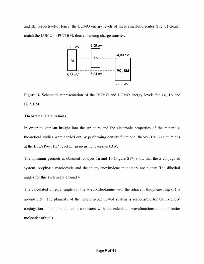
and 1b, respectively. Hence, the LUMO energy levels of these small-molecules (Fig. 3) clearly
match the LUMO of PC71BM, thus enhancing charge transfer.
Figure 3. Schematic representation of the HOMO and LUMO energy levels for 1a, 1b and
PC71BM.
Theoretical Calculations
In order to gain an insight into the structure and the electronic properties of the materials,
theoretical studies were carried out by performing density functional theory (DFT) calculations
at the B3LYP/6-31G* level in vacuo using Gaussian 03W.
The optimum geometries obtained for dyes 1a and 1b (Figure S17) show that the -conjugated
system, porphyrin macrocycle and the thienylenevinylene monomers are planar. The dihedral
angles for this system are around 4°.
The calculated dihedral angle for the N-ethylrhodanine with the adjacent thiophene ring () is
around 1.5°. The planarity of the whole -conjugated system is responsible for the extended
conjugation and this situation is consistent with the calculated wavefunctions of the frontier
molecular orbitals.
Page 10 of 41
The HOMO and LUMO are spread over the whole porphyrin and the corresponding
thienylenvinylene system. Thus, both orbitals are overlapped and this promotes the HOMO to
LUMO electronic transitions (Figure S18).
The theoretical HOMO–LUMO gaps are similar for both dyes, with a slightly lower value for
compound 1b (1.72 eV) than for 1a (1.85 eV). These values are of the same order of magnitude
as those determined by electrochemical measurements.
The greater extent of the conjugation in dye 1b results in an increase in the HOMO energy level
and, as a consequence, a bathochromic shift in the maximum absorption wavelength, which in
turn improves the light harvesting behavior.
The differences between the HOMO of the donor (1a or 1b) and the LUMO of the acceptor
(PC71BM)[24] (1a: 1.12 eV, 1b: 0.86 eV) point to efficient Voc values. Furthermore, the
difference between the LUMO of the dyes 1a and 1b and the LUMO of PC71BM (1a: 0.73 eV,
1b: 0.85 eV) ensures efficient exciton dissociation at the D/A interface.
Device Characterization
The photovoltaic (PV) properties of 1a and 1b were investigated by fabricating solar cells using
the conventional sandwich structure of ITO/poly(3,4-ethylenedioxythiophene):
polystyrenesulfonate (PEDOT:PSS)/small-molecule:acceptor/Ca/Al. The fabrication method and
other details are provided in the Supporting Information. The electrical characterization of all
devices was performed under ambient conditions with AM 1.5 G simulated illumination at an
intensity of 100 mW cm-2
. The current density-voltage characteristics and the external quantum
efficiency (EQE) are shown in Fig. 4 and the performance parameters are summarized in Table 2
as a function of the donor:PC71BM weight ratios . Average values were taken from 12 devices.
Page 11 of 41
The devices based on a 1a:PC71BM blend film with a w/w ratio of 1:2 exhibited an average
power conversion efficiency (PCE) above 3%, with an open-circuit voltage (Voc) of 0.85 V,
high short-circuit current (Jsc) and poor FF of 30.8% (Fig. 4a). On the other hand, the
photovoltaic device with 1b:PC71BM at a blend ratio of 1:4 w/w showed a record PCE of
4.24%, with Voc 0.8 V, a Jsc of 13.2 mA/cm2 and a FF of 40.1% (Fig. 4b). Moreover, the EQE
values, which are displayed in Figures 4c and 4d, were measured under monochromatic light for
1a:PC71BM and 1b:PC71BM complete devices at different blend ratios. Both spectra exhibit a
broad spectral response, ranging from 300 to 800 nm, whereas the mixture of 1b:PC71BM at a
1:4 w/w ratio gave the highest incident photon-to-current efficiency (80%) at 423 nm. This
finding is consistent with the devices with the highest Jsc and PCE. Furthermore, the EQE
integration against the 1.5 AM G sun spectra results was in good agreement with the measured
photocurrents. As can be seen, all the solar cells display fill factor values below 50% (see Table
2). This issue was independent of the donor/acceptor ratio although, for the best solar cells with a
ratio of 1:4 we achieved the highest fill factor values. From these results, it is difficult and too
speculative to infer the reasons for the low fill factor. Nevertheless, we believe that the low
mobility measured for the “only hole devices” and the unbalanced charge transport between
holes and electrons are, definitively important factors that effect a change on the fill factor
Page 12 of 41
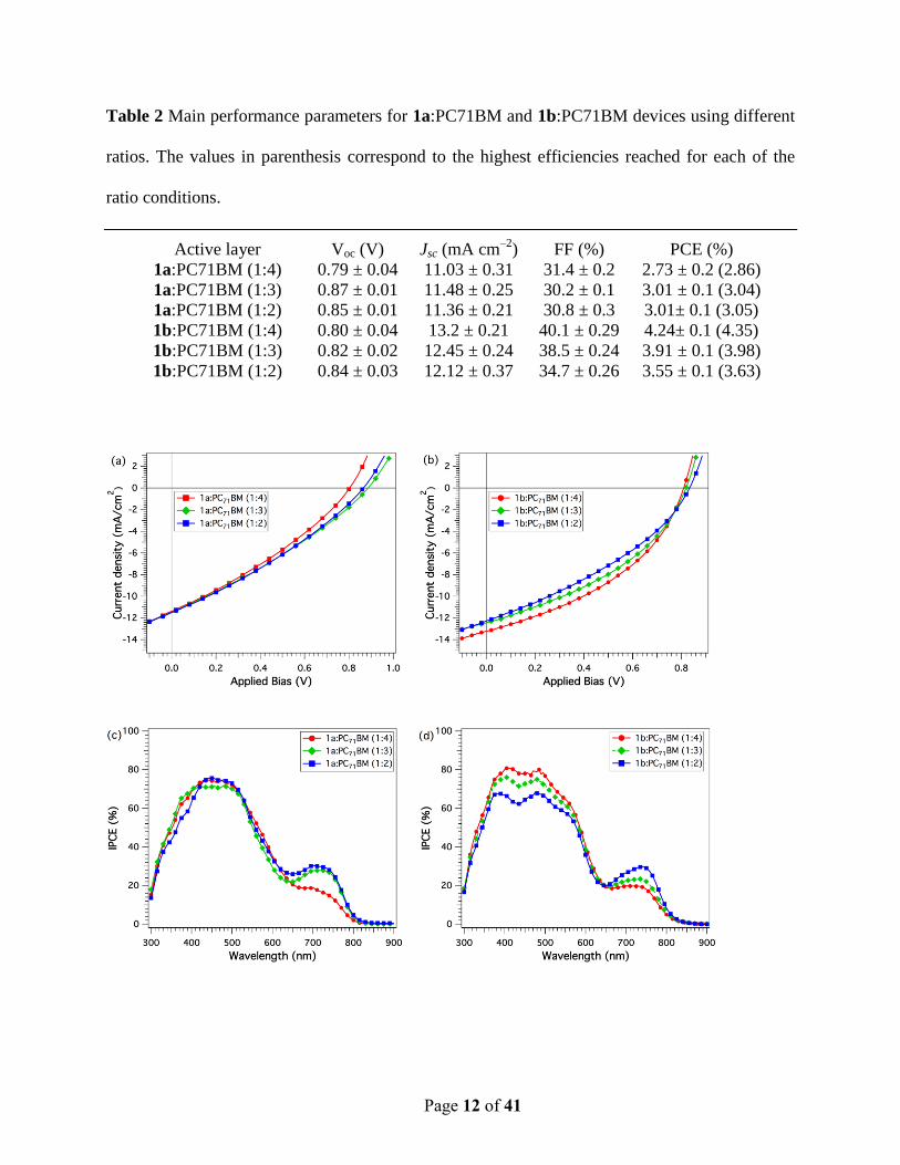
Table 2 Main performance parameters for 1a:PC71BM and 1b:PC71BM devices using different
ratios. The values in parenthesis correspond to the highest efficiencies reached for each of the
ratio conditions.
Active layer Voc (V) Jsc (mA cm–2
) FF (%) PCE (%)
1a:PC71BM (1:4) 0.79 ± 0.04 11.03 ± 0.31 31.4 ± 0.2 2.73 ± 0.2 (2.86)
1a:PC71BM (1:3) 0.87 ± 0.01 11.48 ± 0.25 30.2 ± 0.1 3.01 ± 0.1 (3.04)
1a:PC71BM (1:2) 0.85 ± 0.01 11.36 ± 0.21 30.8 ± 0.3 3.01± 0.1 (3.05)
1b:PC71BM (1:4) 0.80 ± 0.04 13.2 ± 0.21 40.1 ± 0.29 4.24± 0.1 (4.35)
1b:PC71BM (1:3) 0.82 ± 0.02 12.45 ± 0.24 38.5 ± 0.24 3.91 ± 0.1 (3.98)
1b:PC71BM (1:2) 0.84 ± 0.03 12.12 ± 0.37 34.7 ± 0.26 3.55 ± 0.1 (3.63)
Page 13 of 41
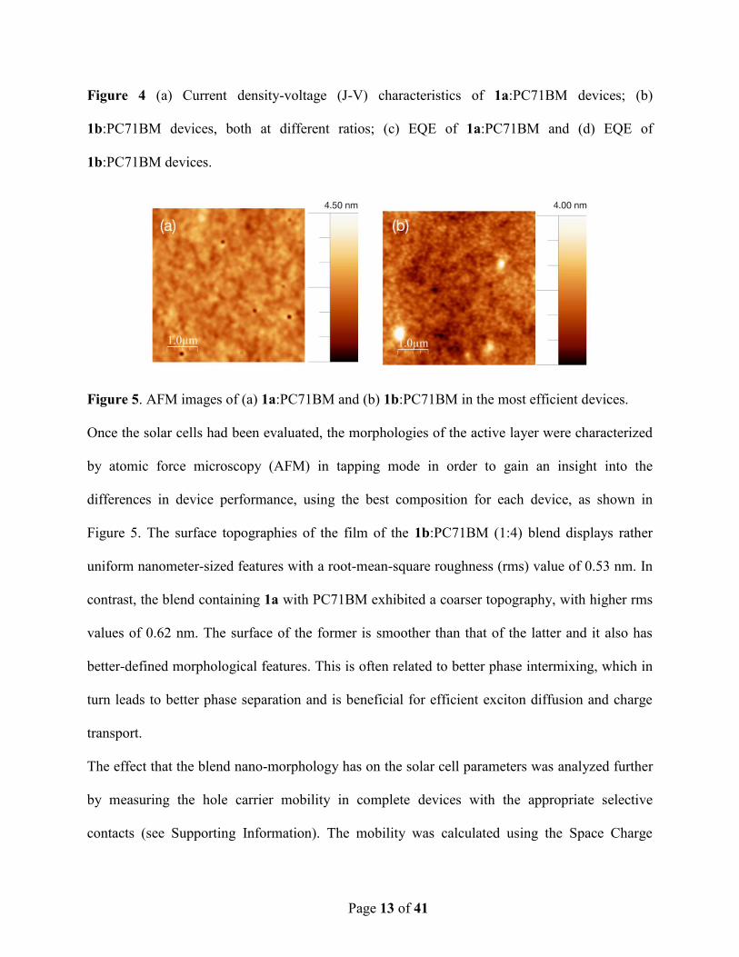
Figure 4 (a) Current density-voltage (J-V) characteristics of 1a:PC71BM devices; (b)
1b:PC71BM devices, both at different ratios; (c) EQE of 1a:PC71BM and (d) EQE of
1b:PC71BM devices.
Figure 5. AFM images of (a) 1a:PC71BM and (b) 1b:PC71BM in the most efficient devices.
Once the solar cells had been evaluated, the morphologies of the active layer were characterized
by atomic force microscopy (AFM) in tapping mode in order to gain an insight into the
differences in device performance, using the best composition for each device, as shown in
Figure 5. The surface topographies of the film of the 1b:PC71BM (1:4) blend displays rather
uniform nanometer-sized features with a root-mean-square roughness (rms) value of 0.53 nm. In
contrast, the blend containing 1a with PC71BM exhibited a coarser topography, with higher rms
values of 0.62 nm. The surface of the former is smoother than that of the latter and it also has
better-defined morphological features. This is often related to better phase intermixing, which in
turn leads to better phase separation and is beneficial for efficient exciton diffusion and charge
transport.
The effect that the blend nano-morphology has on the solar cell parameters was analyzed further
by measuring the hole carrier mobility in complete devices with the appropriate selective
contacts (see Supporting Information). The mobility was calculated using the Space Charge
Page 14 of 41
Limited Current method (SCLC) as described in the Supporting Information (Figure S19).
Values for 1a and 1b of 1.25±0.8×10⁻⁵
Vcm-2
s-1
and 1.53±0.3×10⁻⁵
Vcm–2
s-1
, respectively, were
obtained. It should be noted that, in contrast to previous publications,[33-40] the effect of the
alkyl chains in these molecules on the hole carrier mobility is less critical. Moreover, it was
determined that the hole carrier mobility is not responsible for the difference between the two
porphyrin-based devices and, more importantly, this physical characteristic is not considered to
be a determinant factor for the final device performance.
Finally, the carrier losses were evaluated by measuring the interfacial carrier recombination
kinetics as reported previously.[33, 34, 41-48]
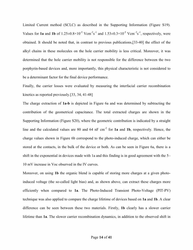
The charge extraction of 1a-b is depicted in Figure 6a and was determined by subtracting the
contribution of the geometrical capacitance. The total extracted charges are shown in the
Supporting Information (Figure S20), where the geometric contribution is indicated by a straight
line and the calculated values are 80 and 64 nF cm-2
for 1a and 1b, respectively. Hence, the
charge values shown in Figure 6b correspond to the photo-induced charge, which can either be
stored at the contacts, in the bulk of the device or both. As can be seen in Figure 6a, there is a
shift in the exponential in devices made with 1a and this finding is in good agreement with the 5–
10 mV increase in Voc observed in the IV curves.
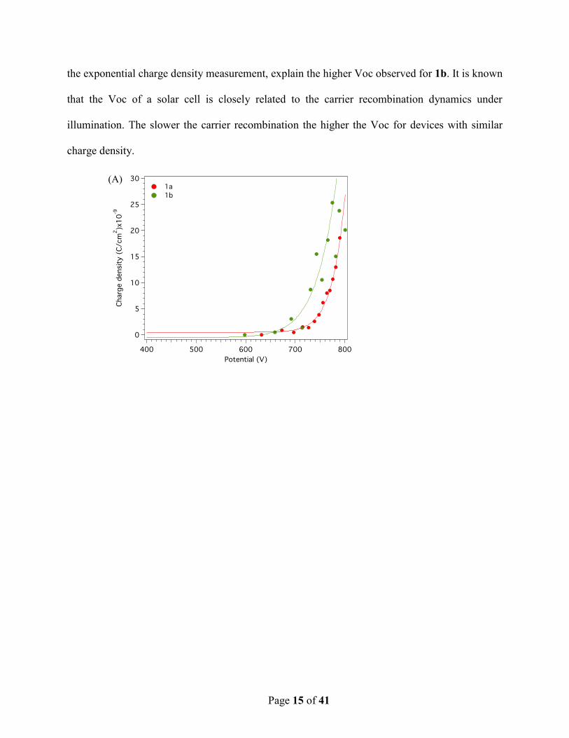
Moreover, on using 1b the organic blend is capable of storing more charges at a given photo-
induced voltage (the so-called light bias) and, as shown above, can extract these charges more
efficiently when compared to 1a. The Photo-Induced Transient Photo-Voltage (PIT-PV)
technique was also applied to compare the charge lifetime of devices based on 1a and 1b. A clear
difference can be seen between these two materials. Firstly, 1b clearly has a slower carrier
lifetime than 1a. The slower carrier recombination dynamics, in addition to the observed shift in
Page 15 of 41
the exponential charge density measurement, explain the higher Voc observed for 1b. It is known
that the Voc of a solar cell is closely related to the carrier recombination dynamics under
illumination. The slower the carrier recombination the higher the Voc for devices with similar
charge density.
(A)
Page 16 of 41
Figure 6. (A) Charge density at different light intensities (light bias) of 1a (red line) and 1b
(green line). The charges correspond to the extracted charges under different illumination
conditions. (B) The carrier life-time of 1a (red line) and 1b (green line) at different charge
values.
The results described above indicate that the molecular structure of 1b favors better film nano-
morphology and thus improved charge collection and slower carrier recombination dynamics.
Conclusions
Two conjugated molecules bearing a Zn-porphyrin, which act as an electron donor, linked by
ethynylene units to one or two thienylenevinylene moieties and capped by ethylenerhodanine
groups as acceptor units have been synthesized and characterized for solution processed small
(B)
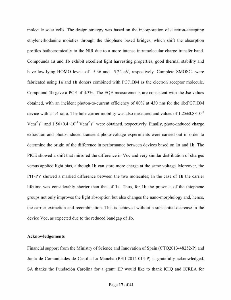
Page 17 of 41
molecule solar cells. The design strategy was based on the incorporation of electron-accepting
ethylenerhodanine moieties through the thiophene based bridges, which shift the absorption
profiles bathocromically to the NIR due to a more intense intramolecular charge transfer band.
Compounds 1a and 1b exhibit excellent light harvesting properties, good thermal stability and
have low-lying HOMO levels of –5.36 and –5.24 eV, respectively. Complete SMOSCs were
fabricated using 1a and 1b donors combined with PC71BM as the electron acceptor molecule.
Compound 1b gave a PCE of 4.3%. The EQE measurements are consistent with the Jsc values
obtained, with an incident photon-to-current efficiency of 80% at 430 nm for the 1b:PC71BM
device with a 1:4 ratio. The hole carrier mobility was also measured and values of 1.25±0.8×10⁻⁵
Vcm-2
s-1
and 1.56±0.4×10⁻⁵
Vcm-2
s-1
were obtained, respectively. Finally, photo-induced charge
extraction and photo-induced transient photo-voltage experiments were carried out in order to
determine the origin of the difference in performance between devices based on 1a and 1b. The
PICE showed a shift that mirrored the difference in Voc and very similar distribution of charges
versus applied light bias, although 1b can store more charge at the same voltage. Moreover, the
PIT-PV showed a marked difference between the two molecules; In the case of 1b the carrier
lifetime was considerably shorter than that of 1a. Thus, for 1b the presence of the thiophene
groups not only improves the light absorption but also changes the nano-morphology and, hence,
the carrier extraction and recombination. This is achieved without a substantial decrease in the
device Voc, as expected due to the reduced bandgap of 1b.
Acknowledgements
Financial support from the Ministry of Science and Innovation of Spain (CTQ2013-48252-P) and
Junta de Comunidades de Castilla-La Mancha (PEII-2014-014-P) is gratefully acknowledged.
SA thanks the Fundación Carolina for a grant. EP would like to thank ICIQ and ICREA for
Page 18 of 41
financial support as well as the MINECO projects CTQ2013-47183r and the Severo Ochoa
Accreditation (SO-2013-0319). L.E. thanks the Robert A. Welch Foundation for an endowed
chair, grant #AH-0033, the US National Science Foundation, grant DMR-1205302 (PREM
Program).
Notes and references
[1] G. Yu, J. Gao, J.C. Hummelen, F. Wudl, A.J. Heeger, Polymer Photovoltaic Cells: Enhanced
Efficiencies via a Network of Internal Donor-Acceptor Heterojunctions, Science, 270 (1995)
1789-1791.
[2] H.-Y. Chen, J. Hou, S. Zhang, Y. Liang, G. Yang, Y. Yang, L. Yu, Y. Wu, G. Li, Polymer
solar cells with enhanced open-circuit voltage and efficiency, Nat Photon, 3 (2009) 649-653.
[3] G. Li, R. Zhu, Y. Yang, Polymer solar cells, Nat Photon, 6 (2012) 153-161.
[4] R.F. Service, Outlook Brightens for Plastic Solar Cells, Science, 332 (2011) 293-293.
[5] T. Yang, M. Wang, C. Duan, X. Hu, L. Huang, J. Peng, F. Huang, X. Gong, Inverted polymer
solar cells with 8.4% efficiency by conjugated polyelectrolyte, Energy & Environmental Science,
5 (2012) 8208-8214.
[6] J. Subbiah, B. Purushothaman, M. Chen, T. Qin, M. Gao, D. Vak, F.H. Scholes, X. Chen,
S.E. Watkins, G.J. Wilson, A.B. Holmes, W.W.H. Wong, D.J. Jones, Organic Solar Cells Using
a High-Molecular-Weight Benzodithiophene–Benzothiadiazole Copolymer with an Efficiency of
9.4%, Advanced Materials, 27 (2015) 702-705.
[7] T. Ameri, N. Li, C.J. Brabec, Highly efficient organic tandem solar cells: a follow up review,
Energy & Environmental Science, 6 (2013) 2390-2413.
[8] F.C. Krebs, N. Espinosa, M. Hösel, R.R. Søndergaard, M. Jørgensen, 25th Anniversary
Article: Rise to Power – OPV-Based Solar Parks, Advanced Materials, 26 (2014) 29-39.
[9] A.J. Heeger, 25th Anniversary Article: Bulk Heterojunction Solar Cells: Understanding the
Mechanism of Operation, Advanced Materials, 26 (2014) 10-28.
[10] C.-C. Chen, W.-H. Chang, K. Yoshimura, K. Ohya, J. You, J. Gao, Z. Hong, Y. Yang, An
Efficient Triple-Junction Polymer Solar Cell Having a Power Conversion Efficiency Exceeding
11%, Advanced Materials, 26 (2014) 5670-5677.
[11] B. Kan, Q. Zhang, M. Li, X. Wan, W. Ni, G. Long, Y. Wang, X. Yang, H. Feng, Y. Chen,
Solution-Processed Organic Solar Cells Based on Dialkylthiol-Substituted Benzodithiophene
Unit with Efficiency near 10%, Journal of the American Chemical Society, 136 (2014) 15529-
15532.
[12] J. Roncali, P. Leriche, P. Blanchard, Molecular Materials for Organic Photovoltaics: Small
is Beautiful, Advanced Materials, 26 (2014) 3821-3838.
[13] Y. Liu, J. Zhao, Z. Li, C. Mu, W. Ma, H. Hu, K. Jiang, H. Lin, H. Ade, H. Yan, Aggregation
and morphology control enables multiple cases of high-efficiency polymer solar cells, Nat
Commun, 5 (2014).
[14] J. Xue, S. Uchida, B.P. Rand, S.R. Forrest, Asymmetric tandem organic photovoltaic cells
with hybrid planar-mixed molecular heterojunctions, Applied Physics Letters, 85 (2004) 5757-
5759.
Page 19 of 41
[15] V. Steinmann, N.M. Kronenberg, M.R. Lenze, S.M. Graf, D. Hertel, K. Meerholz, H.
Bürckstümmer, E.V. Tulyakova, F. Würthner, Simple, Highly Efficient Vacuum-Processed Bulk
Heterojunction Solar Cells Based on Merocyanine Dyes, Advanced Energy Materials, 1 (2011)
888-893.
[16] S. Yoo, B. Domercq, B. Kippelen, Efficient thin-film organic solar cells based on
pentacene/C60 heterojunctions, Applied Physics Letters, 85 (2004) 5427-5429.
[17] G. Wei, S. Wang, K. Sun, M.E. Thompson, S.R. Forrest, Solvent-Annealed Crystalline
Squaraine: PC70BM (1:6) Solar Cells, Advanced Energy Materials, 1 (2011) 184-187.
[18] B. Walker, A.B. Tamayo, X.-D. Dang, P. Zalar, J.H. Seo, A. Garcia, M. Tantiwiwat, T.-Q.
Nguyen, Nanoscale Phase Separation and High Photovoltaic Efficiency in Solution-Processed,
Small-Molecule Bulk Heterojunction Solar Cells, Advanced Functional Materials, 19 (2009)
3063-3069.
[19] J. Kesters, P. Verstappen, M. Kelchtermans, L. Lutsen, D. Vanderzande, W. Maes,
Porphyrin-Based Bulk Heterojunction Organic Photovoltaics: The Rise of the Colors of Life,
Advanced Energy Materials, 5 (2015) n/a-n/a.
[20] H. Imahori, T. Umeyama, S. Ito, Large π-Aromatic Molecules as Potential Sensitizers for
Highly Efficient Dye-Sensitized Solar Cells, Accounts of Chemical Research, 42 (2009) 1809-
1818.
[21] L. Li, Y. Huang, J. Peng, Y. Cao, X. Peng, Enhanced performance of solution-processed
solar cells based on porphyrin small molecules with a diketopyrrolopyrrole acceptor unit and a
pyridine additive, Journal of Materials Chemistry A, 1 (2013) 2144-2150.
[22] H. Qin, L. Li, F. Guo, S. Su, J. Peng, Y. Cao, X. Peng, Solution-processed bulk
heterojunction solar cells based on a porphyrin small molecule with 7% power conversion
efficiency, Energy & Environmental Science, 7 (2014) 1397-1401.
[23] C. Vijay Kumar, L. Cabau, E.N. Koukaras, G.D. Sharma, E. Palomares, Synthesis, optical
and electrochemical properties of the A-[small pi]-D-[small pi]-A porphyrin and its application
as an electron donor in efficient solution processed bulk heterojunction solar cells, Nanoscale, 7
(2015) 179-189.
[24] J. Rawson, A.C. Stuart, W. You, M.J. Therien, Tailoring Porphyrin-Based Electron
Accepting Materials for Organic Photovoltaics, Journal of the American Chemical Society, 136
(2014) 17561-17569.
[25] S. Chen, L. Xiao, X. Zhu, X. Peng, W.-K. Wong, W.-Y. Wong, Solution-processed new
porphyrin-based small molecules as electron donors for highly efficient organic photovoltaics,
Chemical Communications, 51 (2015) 14439-14442.
[26] H. Wang, L. Xiao, L. Yan, S. Chen, X. Zhu, X. Peng, X. Wang, W.-K. Wong, W.-Y. Wong,
Structural engineering of porphyrin-based small molecules as donors for efficient organic solar
cells, Chemical Science, 7 (2016) 4301-4307.
[27] K. Gao, L. Li, T. Lai, L. Xiao, Y. Huang, F. Huang, J. Peng, Y. Cao, F. Liu, T.P. Russell,
R.A.J. Janssen, X. Peng, Deep Absorbing Porphyrin Small Molecule for High-Performance
Organic Solar Cells with Very Low Energy Losses, Journal of the American Chemical Society,
137 (2015) 7282-7285.
[28] A. Yella, H.-W. Lee, H.N. Tsao, C. Yi, A.K. Chandiran, M.K. Nazeeruddin, E.W.-G. Diau,
C.-Y. Yeh, S.M. Zakeeruddin, M. Grätzel, Porphyrin-Sensitized Solar Cells with Cobalt
(II/III)–Based Redox Electrolyte Exceed 12 Percent Efficiency, Science, 334 (2011) 629-634.
Page 20 of 41
[29] S. Arrechea, A.n. Molina-Ontoria, A. Aljarilla, P. de la Cruz, F. Langa, L. Echegoyen, New
acceptor‚p-porphyrin‚p-acceptor systems for solution-processed small molecule organic solar
cells, Dyes and Pigments, 121 (2015) 109-117.
[30] A. Cravino, Origin of the open circuit voltage of donor-acceptor solar cells: Do polaronic
energy levels play a role?, Applied Physics Letters, 91 (2007) 243502.
[31] G. Dennler, M.C. Scharber, C.J. Brabec, Polymer-Fullerene Bulk-Heterojunction Solar
Cells, Advanced Materials, 21 (2009) 1323-1338.
[32] M.C. Scharber, D. Mühlbacher, M. Koppe, P. Denk, C. Waldauf, A.J. Heeger, C.J. Brabec,
Design Rules for Donors in Bulk-Heterojunction Solar Cells—Towards 10 % Energy-
Conversion Efficiency, Advanced Materials, 18 (2006) 789-794.
[33] N.F. Montcada, L. Cabau, C.V. Kumar, W. Cambarau, E. Palomares, Indoline as electron
donor unit in “Push–Pull” organic small molecules for solution processed organic solar
cells: Effect of the molecular π-bridge on device efficiency, Organic Electronics, 20 (2015)
15-23.
[34] N.F. Montcada, R. Dominguez, B. Pelado, P.d.l. Cruz, E. Palomares, A. Viterisi, F. Langa,
Correction: High photocurrent in oligo-thienylenevinylene-based small molecule solar cells with
4.9% solar-to-electrical energy conversion, Journal of Materials Chemistry A, 3 (2015) 12097-
12097.
[35] G.F.A. Dibb, F.C. Jamieson, A. Maurano, J. Nelson, J.R. Durrant, Limits on the Fill Factor
in Organic Photovoltaics: Distinguishing Nongeminate and Geminate Recombination
Mechanisms, The Journal of Physical Chemistry Letters, 4 (2013) 803-808.
[36] T. Kirchartz, T. Agostinelli, M. Campoy-Quiles, W. Gong, J. Nelson, Understanding the
Thickness-Dependent Performance of Organic Bulk Heterojunction Solar Cells: The Influence of
Mobility, Lifetime, and Space Charge, The Journal of Physical Chemistry Letters, 3 (2012)
3470-3475.
[37] B.-G. Kim, X. Ma, C. Chen, Y. Ie, E.W. Coir, H. Hashemi, Y. Aso, P.F. Green, J. Kieffer, J.
Kim, Energy Level Modulation of HOMO, LUMO, and Band-Gap in Conjugated Polymers for
Organic Photovoltaic Applications, Advanced Functional Materials, 23 (2013) 439-445.
[38] Y. Li, Molecular Design of Photovoltaic Materials for Polymer Solar Cells: Toward
Suitable Electronic Energy Levels and Broad Absorption, Accounts of Chemical Research, 45
(2012) 723-733.
[39] J. Zhou, X. Wan, Y. Liu, Y. Zuo, Z. Li, G. He, G. Long, W. Ni, C. Li, X. Su, Y. Chen,
Small Molecules Based on Benzo[1,2-b:4,5-b′]dithiophene Unit for High-Performance
Solution-Processed Organic Solar Cells, Journal of the American Chemical Society, 134 (2012)
16345-16351.
[40] A. Mishra, P. Bäuerle, Small Molecule Organic Semiconductors on the Move: Promises for
Future Solar Energy Technology, Angewandte Chemie International Edition, 51 (2012) 2020-
2067.
[41] C.G. Shuttle, A. Maurano, R. Hamilton, B. O’Regan, J.C. de Mello, J.R. Durrant, Charge
extraction analysis of charge carrier densities in a polythiophene/fullerene solar cell: Analysis of
the origin of the device dark current, Applied Physics Letters, 93 (2008) 183501.
[42] A. Sánchez-Díaz, M. Izquierdo, S. Filippone, N. Martin, E. Palomares, The Origin of the
High Voltage in DPM12/P3HT Organic Solar Cells, Advanced Functional Materials, 20 (2010)
2695-2700.

Page 21 of 41
[43] A. Sánchez-Díaz, R. Pacios, U. Muñecas, T. Torres, E. Palomares, Charge transfer reactions
in near IR absorbing small molecule solution processed organic bulk-heterojunction solar,
Organic Electronics, 12 (2011) 329-335.
[44] A. Guerrero, N.F. Montcada, J. Ajuria, I. Etxebarria, R. Pacios, G. Garcia-Belmonte, E.
Palomares, Charge carrier transport and contact selectivity limit the operation of PTB7-based
organic solar cells of varying active layer thickness, Journal of Materials Chemistry A, 1 (2013)
12345-12354.
[45] N.r.F. Montcada, B. Pelado, A. Viterisi, J. Albero, J. Coro, P.d.l. Cruz, F. Langa, E.
Palomares, High open circuit voltage in efficient thiophene-based small molecule solution
processed organic solar cells, Organic Electronics, 14 (2013) 2826-2832.
[46] D. Fernandez, A. Viterisi, J.W. Ryan, F. Gispert-Guirado, S. Vidal, S. Filippone, N. Martin,
E. Palomares, Small molecule BHJ solar cells based on DPP(TBFu)2 and
diphenylmethanofullerenes (DPM): linking morphology, transport, recombination and
crystallinity, Nanoscale, 6 (2014) 5871-5878.
[47] J.W. Ryan, T. Kirchartz, A.l. Viterisi, J. Nelson, E. Palomares, Understanding the Effect of
Donor Layer Thickness and a MoO3 Hole Transport Layer on the Open-Circuit Voltage in
Squaraine/C60 Bilayer Solar Cells, The Journal of Physical Chemistry C, 117 (2013) 19866-
19874.
[48] A. Sánchez-Díaz, L. Burtone, M. Riede, E. Palomares, Measurements of Efficiency Losses
in Blend and Bilayer-Type Zinc Phthalocyanine/C60 High-Vacuum-Processed Organic Solar
Cells, The Journal of Physical Chemistry C, 116 (2012) 16384-16390.
Supplementary Information.
High Current Porphyrin Core Based A-π-D-π-A Small Molecule for Solution
Processed Organic Solar Cells
Núria Fernández,c Susana Arrechea,
a Agustín Molina-Ontoria,
b Ana Aljarilla,
a Pilar de
la Cruz,a Luis Echegoyen,
b* Emilio Palomares,
c,d* and Fernando Langa
a*
a Universidad de Castilla-La Mancha. Institute of Nanoscience, Nanotechnology and
Molecular Materials (INAMOL), Campus de la Fábrica de Armas, Toledo. Spain. Tel:
34 9252 68843. E-mail: [email protected]
bDepartment of Chemistry, University of Texas at El Paso, El Paso, TX 79968. USA.
Tel: 915-747-7573.
cInstitute of Chemical Research of Catalonia (ICIQ). The Barcelona Institute of Science
and Technology. Avda. Països Catalans, 14. Tarragona. E-43007. Spain. E-mail:
[email protected] [email protected]
d ICREA. Passeig Lluis Companys, 23. Barcelona. E-08010. Spain.
TABLE OF CONTENTS
1. Experimental details S2
2. 1H -NMR,
13C-NMR, FT-IR and MALDI-TOF MS spectra S6
3. Thermogravimetric analysis S12
4. Absorption and emission spectroscopies S13
5. Cyclic and Square Wave voltammetry plots S15
6. Hole mobility measurement S17
7. Charge Extraction and Transient Photo-Voltage details S18

S2
S3
1. Experimental details
Synthetic procedures were carried out under inert argon atmosphere, in dry solvent
unless otherwise noted. All reagents and solvents were reagent grade and were used
without further purification. Chromatographic purifications were performed using silica
gel 60 SDS (particle size 0.040-0.063 mm). Analytical thin-layer chromatography was
performed using Merck TLC silica gel 60 F254. 1H-NMR spectra were obtained on
Bruker TopSpin AV-400 (400 MHz) spectrometer. Chemical shifts are reported in parts
per million (ppm) relative to the solvent residual peak (CDCl3, 7.27 ppm). 13
C-NMR
chemical shifts () are reported relative to the solvent residual peak (CDCl3, 77.0 ppm).
UV-Vis measurements were carried out on a Shimadzu UV 3600 spectrophotometer.
For extinction coefficient determination, solutions of different concentration were
prepared in CH2Cl2 (HPLC grade) with absorption between 0.1-1 of absorbance using a
1 cm UV cuvette. The emission measurements were carried out on Cary Eclipse
fluorescence spectrophotometer. Mass spectra (MALDI-TOF) were recorded on a
VOYAGER DETM
STR mass spectrometer using dithranol as matrix. Melting points are
uncorrected.
The molecular geometries and frontier molecular orbitals of these new dyes have been
optimized by density functional theory (DFT) calculations at the B3LYP/6-31G* level.1
Cyclic and Square Wave voltammetries were performed in ODCB-acetonitrile (4:1)
solutions. Tetrabutylammonium perchlorate (0.1 M as supporting electrolyte) were
purchased from Acros and used without purification. Solutions were deoxygenated by
1 Gaussian 03, Revision D.02, Frisch, M. J.; Trucks, G. W.; Schlegel, H. B.; Scuseria,
G. E.; Robb, M. A.; Cheeseman, J. R.; Montgomery Jr., J. A.; Vreven, T.; Kudin, K. N.;
Burant, J. C.; Millam, J. M.; Iyengar, S. S.; Tomasi, J.; Barone, V.; Mennucci, B.;
Cossi, M.; Scalmani, G.; Rega, N.; Petersson, G. A.; Nakatsuji, H.; Hada, M.; Ehara,
M.; Toyota, K.; Fukuda, R.; Hasegawa, J.; Ishida, M.; Nakajima, T.; Honda, Y.; Kitao,
O.; Nakai, H.; Klene, M.; Li, X.; Knox, J. E.; Hratchian, H. P.; Cross, J. B.; Bakken, V.;
Adamo, C.; Jaramillo, J.; Gomperts, R.; Stratmann, R. E.; Yazyev, O.; Austin, A. J.;
Cammi, R.; Pomelli, C.; Ochterski, J. W.; Ayala, P. Y.; Morokuma, K.; Voth, G. A.;
Salvador, P.; Dannenberg, J. J.; Zakrzewski, V. G.; Dapprich, S.; Daniels, A. D.; Strain,
M. C.; Farkas, O.; Malick, D. K.; Rabuck, A. D.; Raghavachari, K.; Foresman, J. B.;
Ortiz, J. V.; Cui, Q.; Baboul, A. G.; Clifford, S.; Cioslowski, J.; Stefanov, B. B.; Liu,
G.; Liashenko, A.; Piskorz, P.; Komaromi, I.; Martin, R. L.; Fox, D. J.; Keith, T.; Al-
Laham, M. A.; Peng, C. Y.; Nanayakkara, A.; Challacombe, M.; Gill, P. M. W.;
Johnson, B.; Chen, W.; Wong, M. W.; Gonzalez, C.; Pople, J. A. Gaussian, Inc.,
Wallingford CT, 2004.
S4
argon bubbling prior to each experiment which was run under argon atmosphere.
Experiments were done in a one-compartment cell equipped with a platinum working
microelectrode ( = 2 mm) and a platinum wire counter electrode. An Ag/AgNO3 (0.01
M in CH3CN) electrode was used as reference and checked against the
ferrocene/ferrocenium couple (Fc/Fc+) before and after each experiment.
The thermal stability was evaluated by TGA on a Mettler Toledo TGA/DSC Starte
System under nitrogen, with a heating rate of 10 ºC/min. Heating of crystalline samples
leads to melting of the solids, but no recrystallization was observed.
SM BHJ device preparation
PC71BM were purchased from American Dye Source and used as received. The ITO-
coated glasses (Delta technologies, 5-15 Ω) were pre-cleaned stepwise by
ultracentrifugation 15 minutes in detergent, deionized water, methanol, acetone and iso-
propanol and then by a 30 minutes UV-ozone treatment. A thin layer of PEDOT:PSS
(Clevios P VP AI 4083, 5000 rpm, 30 seconds, 30 nm) was spin-coated onto the ITO
and baked at 150 ºC for 15 minutes in air. Subsequently, the active layer (1a-b:PC61BM,
30 mg/mL) with varying weight ratios (1:4, 1:2 and 1:1) was spin-coated at 1500 rpm
from chlorobenzene solutions. 1a or 1b, 1a-b:PC71BM (1:2, 30 mg/mL) was spin-
coated at 1500 rpm. Then the devices were transferred to a N2 filled glove box (<0.1
ppm O2 and < 0.1 ppm H2O) for further processing. The photoactive layer was annealed
at 80 ºC for 10 minutes followed by thermal evaporation of 20 nm of calcium and 80
nm of aluminum (1 x 10⁻⁶
mbar) with a shadow mask of 0.4 cm2.
Device characterization.
The Jsc–Voc values were recorded with a Keithley 2420 source unit. CE and TPV
measurements were carried out using a white LED ring LUXEON® Lumileds and the
signal measured in an oscilloscope Yokogawa DLM2052 registering the drops in
voltage.
S5
Synthetic Procedure
General method for the Knoevenagel condensations. To a solution of 2a-b (1 eq) in
75 mL/mmol of CHCl3. 3-ethylrhodanine (10 eq) and 3 drops of piperidine were added.
The reaction mixture was refluxed and stirred for 12 h and quenched by the addition of
water and extracted with CHCl3 (3 x 150 mL). The combined organic extract was dried
over anhydrous MgSO4 and filtered. The solvent was removed by rotary evaporation.
The product was purified by column chromatography (silica gel, CHCl3) and
recrystallized with CH2Cl2: MeOH.
1a: Using the general procedure previously described from 2a (0.06 mmol, 80 mg) in 5
mL of CHCl3, 3-ethylrhodanine (0.65 mmol, 110 mg). 1a was obtained as a green solid
(81 mg, 0.05 mmol, 82% yield). M. p. > 300°C. 1
H NMR (400 MHz, CDCl3) δ/ppm:
9.57 (d, 4H, J = 4.8 Hz), 8.78 (d, 4H, J = 4.4 Hz), 8.00 (s, 2H), 7.33 (s, 4H), 4.22 (d,
4H, J = 5.7 Hz), 3.11 (m, 4H), 2.88 (m, 4H), 2.67 (s, 6H), 1.88 (s, 12 H), 1.65 (m, 8H),
1.54-1.52 (m, 12H), 1.39-1.30 (m,18), 0.95 (m, 6H), 0.81- 0.77 (m, 6H).13
C NMR (100
MHz, CDCl3) δ/ppm: 192.4, 167.6, 151.7, 150.2, 149.2, 148.4, 139.1, 138.0, 133.7,
132.0, 131.3, 128.0, 127.7, 123.6, 122.3, 120.7, 40.1, 32.0, 31.9, 31.7, 31.0, 29.9, 29.6,
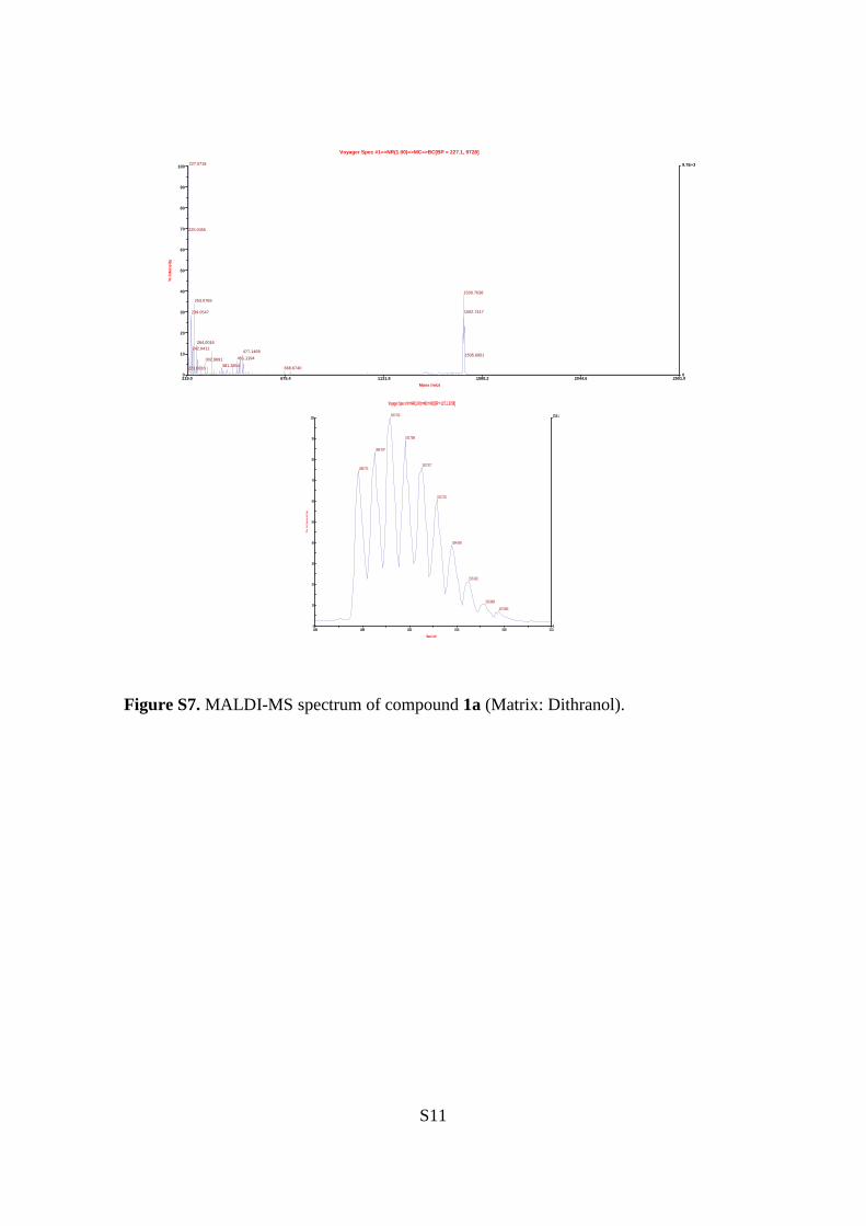
29.4, 28.1, 22.8, 21.7, 21.6, 14.2, 14.1, 12.5. MALDI-TOF MS (m/z): [M]+ calculated
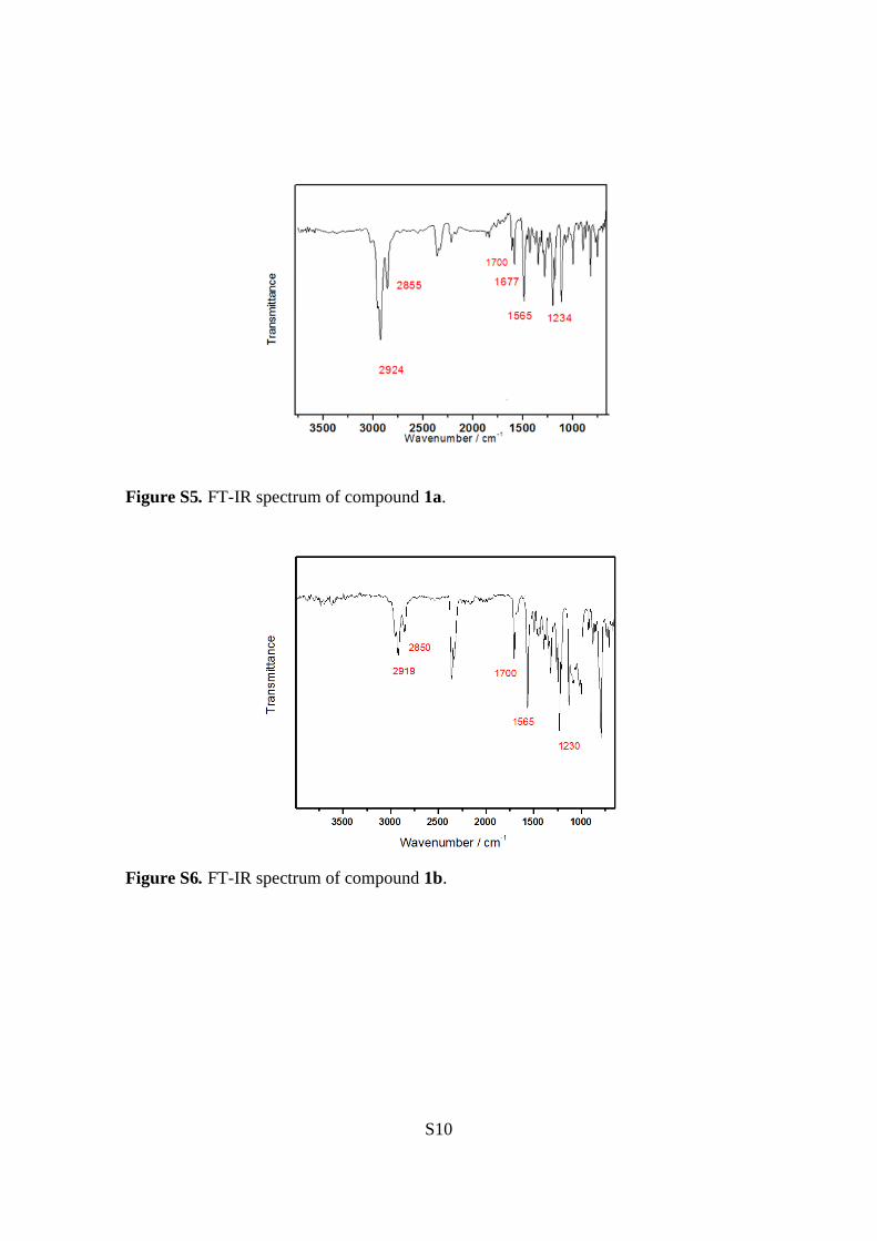
for C88H94N6S6O2Zn: 1498.51; found:1498.75. FT-IR (ATR) υ/cm-1
: 2924, 2855, 1700,
1677, 1565, 1500, 1400, 1322, 1234, 1203, 1130, 998, 883, 794, 709.
1b: Using the general procedure previously described from 2b (0.04 mmol, 80 mg) in 5
mL of CHCl3, 3-ethylrhodanine (0.45 mmol, 72 mg). 1b was obtained as a green solid
(42 mg, 0.05 mmol, 45% yield). M. p. > 300°C. 1H NMR (400 MHz, CDCl3) δ/ppm:
9.58 (d, 4H, J = 4.1 Hz), 8.74 (d, 4H, J = 3.4 Hz), 7.95 (s, 2H), 7.36 (d, 2H), 7.32 (s,
4H), 7.18 (d, 2H, J = 15.4 Hz), 4.22 (d, 4H, J = 6.8 Hz), 3.35, (m, 2H), 3.08 (t, 4H, J =
6.8 Hz), 2.82-2.67 (s, 14H), 2.18 (s, 12H), 1.95-1.85 (m, 14H), 1.67 (t, 4H, J = 5.79
Hz), 1.55 (s,12H), 1.43-1.26 (m, 30H), 0.97-0.80 (m, 18H), 0.08 (t, 18H, J = 4.3 Hz).
13C NMR (100 MHz, CDCl3) δ/ppm: 192.7, 167.7, 151.9, 151.0, 149.9, 149.0, 145.7,
142.8, 142.6, 139.3, 138.1, 137.8, 131.8, 131.4, 130.9, 128.0, 121.8, 119.3, 101.6,
101.1, 40.2, 32.1, 31.9, 31.9, 31.8, 31.7, 31.4, 31.2, 30.0, 29.6, 29.6, 27.7, 22.9, 22.8,
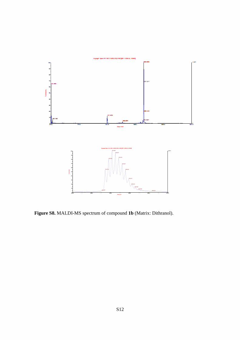
21.8, 14.5, 14.4, 14.3, 12.6. MALDI-TOF MS (m/z): [M]+ calculated for
S6
C122H150N6O2S8Zn: 2050.89; found: 2051.69. FT-IR (ATR) υ/cm-1
: 2958, 2919, 2850,
1700, 1565, 1496, 1457, 1434, 1392,1322, 1261,1230, 1130, 1091, 998, 925, 883, 794,
736.
S7
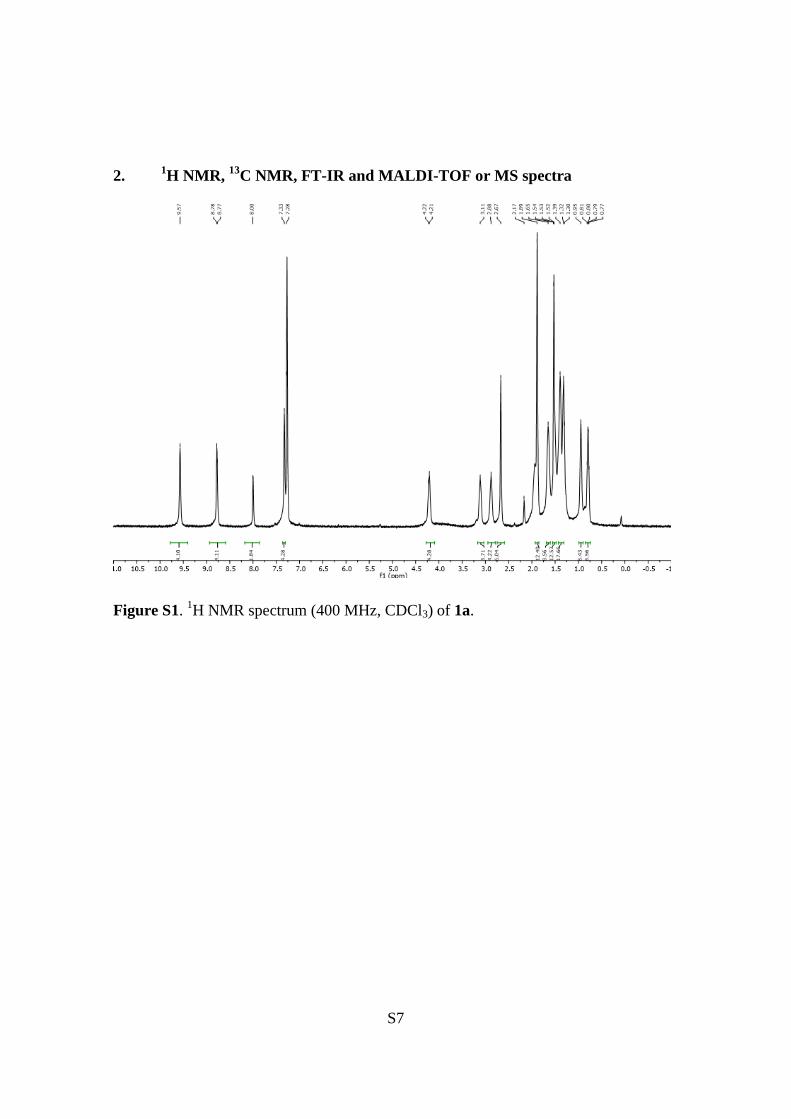
2. 1H NMR,
13C NMR, FT-IR and MALDI-TOF or MS spectra
Figure S1. 1H NMR spectrum (400 MHz, CDCl3) of 1a.
S8
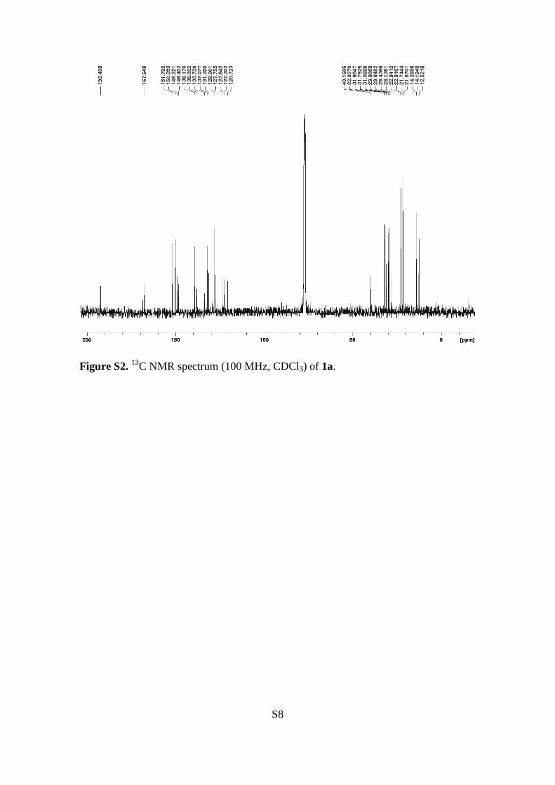
Figure S2. 13
C NMR spectrum (100 MHz, CDCl3) of 1a.
S9
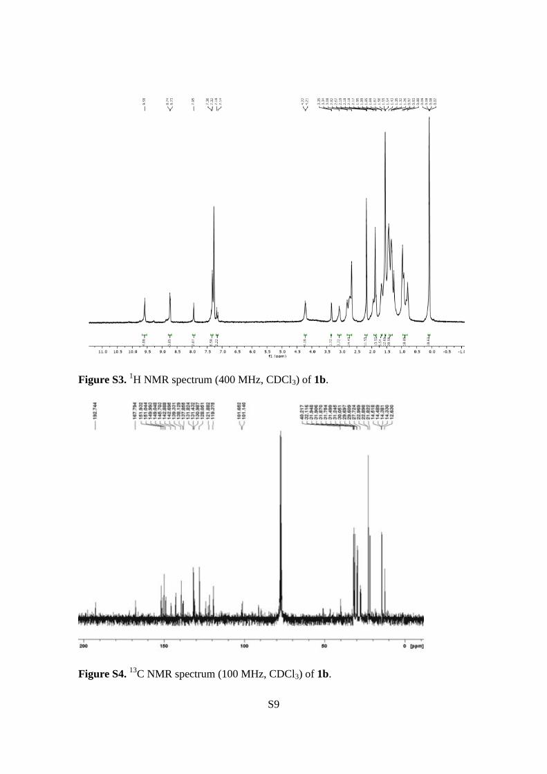
Figure S3. 1H NMR spectrum (400 MHz, CDCl3) of 1b.
Figure S4. 13
C NMR spectrum (100 MHz, CDCl3) of 1b.
S10
Figure S5. FT-IR spectrum of compound 1a.
Figure S6. FT-IR spectrum of compound 1b.
S11
219.0 675.4 1131.8 1588.2 2044.6 2501.0
Mass (m/z)
0
9.7E+3
0
10
20
30
40
50
60
70
80
90
100%
In
ten
sit
y
Voyager Spec #1=>NR(1.00)=>MC=>BC[BP = 227.1, 9728]
227.0718
225.0455
1500.7638
253.0769
1502.7417239.0547
264.0016
242.0411477.1468
1505.6951451.1194302.9691
381.2854668.6740223.0816
1496 1499 1502 1505 1508 1511
Mass (m/z)
0
3715.1
0
10
20
30
40
50
60
70
80
90
100
% In
ten
sity
Voyager Spec #1=>NR(1.00)=>MC=>BC[BP = 227.1, 9728]
1500.7638
1501.7566
1499.7947
1502.74171498.7751
1503.7221
1504.6899
1505.6951
1506.6930
1507.5848
Figure S7. MALDI-MS spectrum of compound 1a (Matrix: Dithranol).
S12
2043.0 2048.6 2054.2 2059.8 2065.4 2071.0
Mass (m/z)
0
1.1E+4
0
10
20
30
40
50
60
70
80
90
100
% In
ten
sity
Voyager Spec #1=>BC=>NR(2.00)=>MC[BP = 2054.6, 10968]
2054.5848
2055.5670
2056.5355
2053.5929
2057.5577
2052.6115 2058.5440
2059.5187
2060.4404
2061.3032
2062.3903
2051.69072066.3112
Figure S8. MALDI-MS spectrum of compound 1b (Matrix: Dithranol).
S13
3. Thermogravimetric analysis
0 200 400 600 800 1000
30
40
50
60
70
80
90
100
110
We
igh
t / %
T / ؛C
T=377OC
Figure S9. Thermogravimetric analysis of 1a.
0 200 400 600 800 1000
10
20
30
40
50
60
70
80
90
100
110
We
igh
t / %
T / ؛C
T=355OC
Figure S10. Thermogravimetric analysis of 1b.
S14
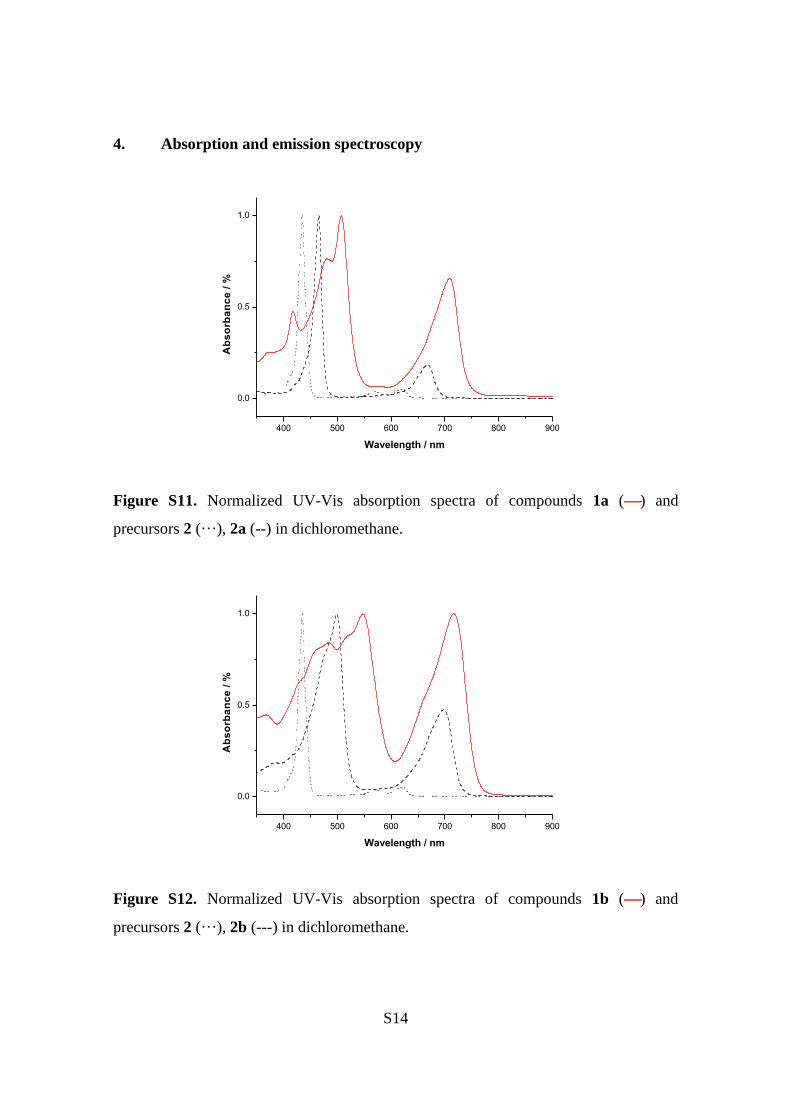
4. Absorption and emission spectroscopy
400 500 600 700 800 900
0.0
0.5
1.0
Ab
so
rba
nc
e /
%
Wavelength / nm
Figure S11. Normalized UV-Vis absorption spectra of compounds 1a () and
precursors 2 (···), 2a (--) in dichloromethane.
400 500 600 700 800 900
0.0
0.5
1.0
Ab
so
rba
nc
e /
%
Wavelength / nm
Figure S12. Normalized UV-Vis absorption spectra of compounds 1b () and
precursors 2 (···), 2b (---) in dichloromethane.
S15
400 500 600 700 800 900
0.0
0.5
1.0
Inte
ns
ity
/a.u
Ab
so
rba
nc
e /
%
Wavelength / nm
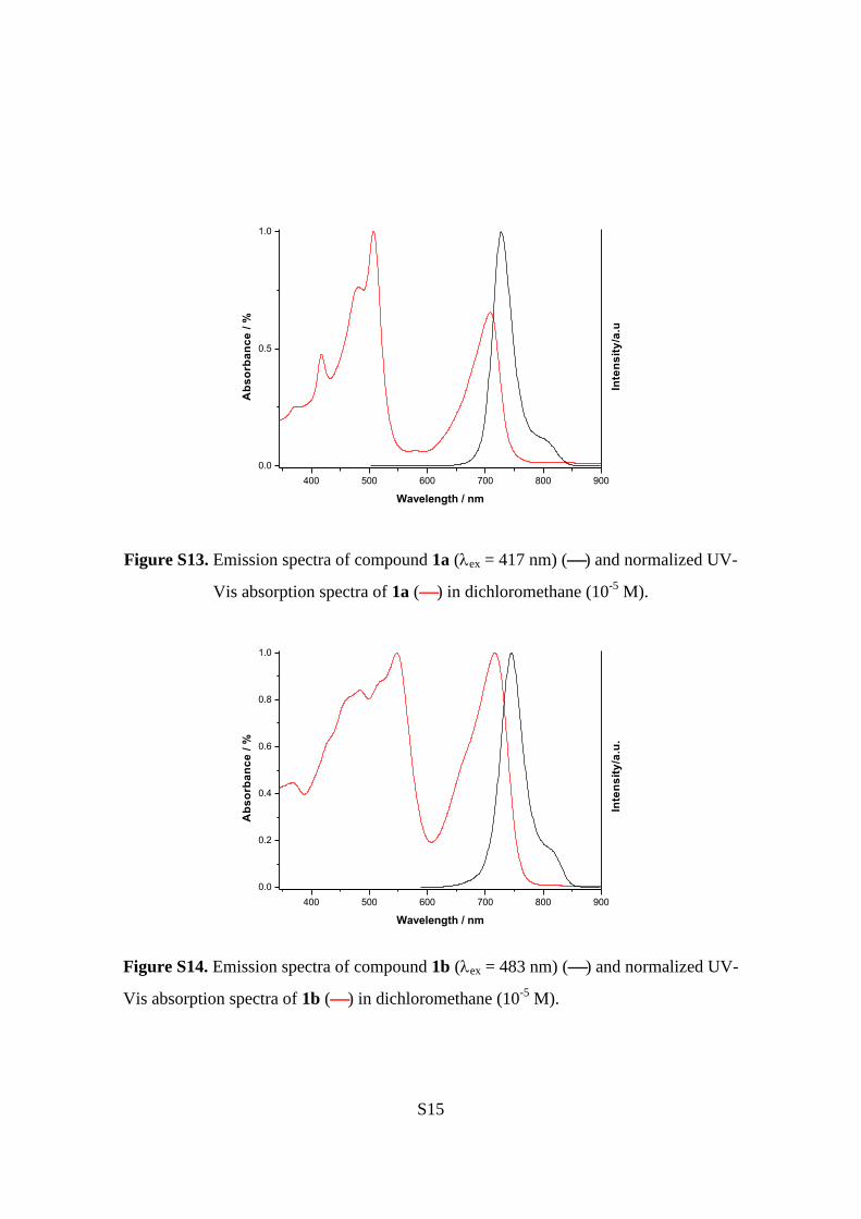
Figure S13. Emission spectra of compound 1a (ex = 417 nm) () and normalized UV-
Vis absorption spectra of 1a () in dichloromethane (10-5
M).
400 500 600 700 800 900
0.0
0.2
0.4
0.6
0.8
1.0
In
ten
sit
y/a
.u.
Ab
so
rba
nc
e /
%
Wavelength / nm
Figure S14. Emission spectra of compound 1b (ex = 483 nm) () and normalized UV-
Vis absorption spectra of 1b () in dichloromethane (10-5
M).
S16
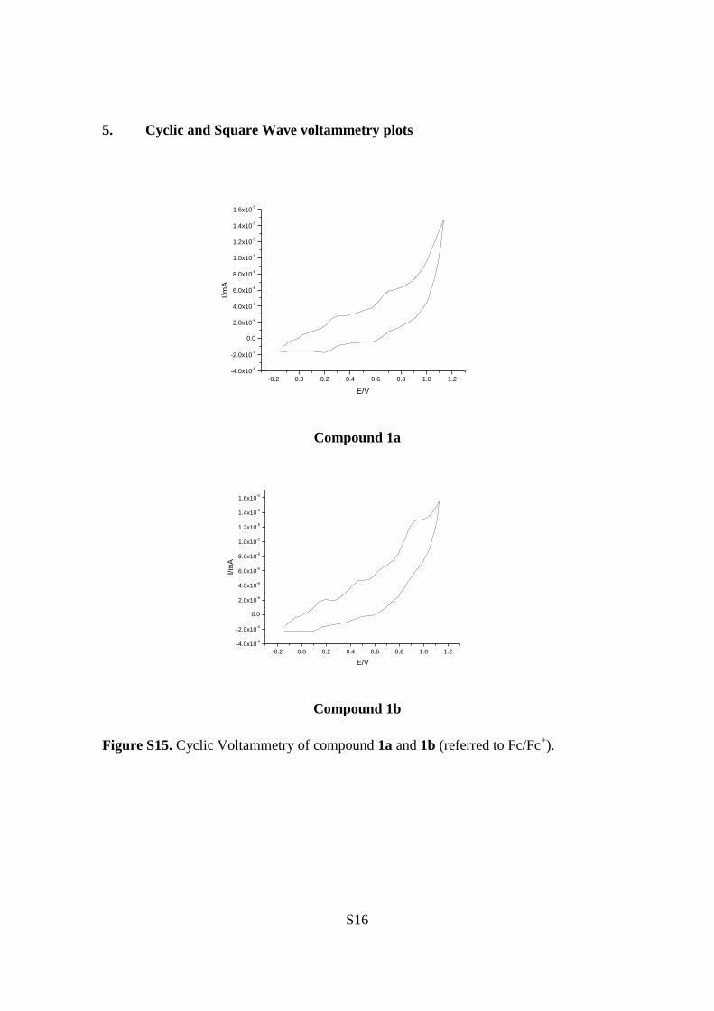
5. Cyclic and Square Wave voltammetry plots
-0.2 0.0 0.2 0.4 0.6 0.8 1.0 1.2
-4.0x10⁻⁶
-2.0x10⁻⁶
0.0
2.0x10⁻⁶
4.0x10⁻⁶
6.0x10⁻⁶
8.0x10⁻⁶
1.0x10⁻⁵
1.2x10⁻⁵
1.4x10⁻⁵
1.6x10⁻⁵
I/m
A
E/V
Compound 1a
-0.2 0.0 0.2 0.4 0.6 0.8 1.0 1.2
-4.0x10⁻⁶
-2.0x10⁻⁶
0.0
2.0x10⁻⁶
4.0x10⁻⁶
6.0x10⁻⁶
8.0x10⁻⁶
1.0x10⁻⁵
1.2x10⁻⁵
1.4x10⁻⁵
1.6x10⁻⁵
I/m
A
E/V
Compound 1b
Figure S15. Cyclic Voltammetry of compound 1a and 1b (referred to Fc/Fc+).
S17
-0.2 0.0 0.2 0.4 0.6 0.8
-2.0x10⁻⁷
0.0
2.0x10⁻⁷
4.0x10⁻⁷
6.0x10⁻⁷
8.0x10⁻⁷
1.0x10⁻⁶
1.2x10⁻⁶
1.4x10⁻⁶
1.6x10⁻⁶
1.8x10⁻⁶
I/m
A
E/V
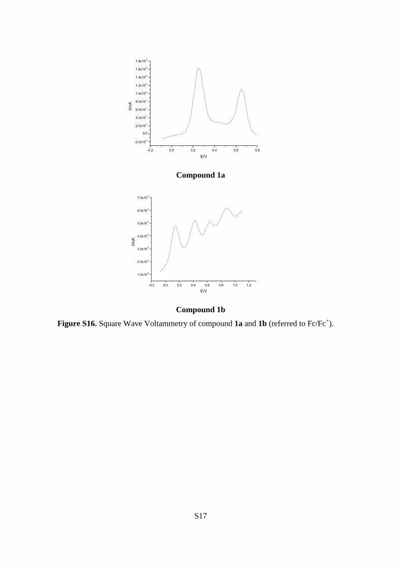
Compound 1a
-0.2 0.0 0.2 0.4 0.6 0.8 1.0 1.2
1.0x10⁻⁶
2.0x10⁻⁶
3.0x10⁻⁶
4.0x10⁻⁶
5.0x10⁻⁶
6.0x10⁻⁶
7.0x10⁻⁶
I/m
A
E/V
Compound 1b
Figure S16. Square Wave Voltammetry of compound 1a and 1b (referred to Fc/Fc+).
S18
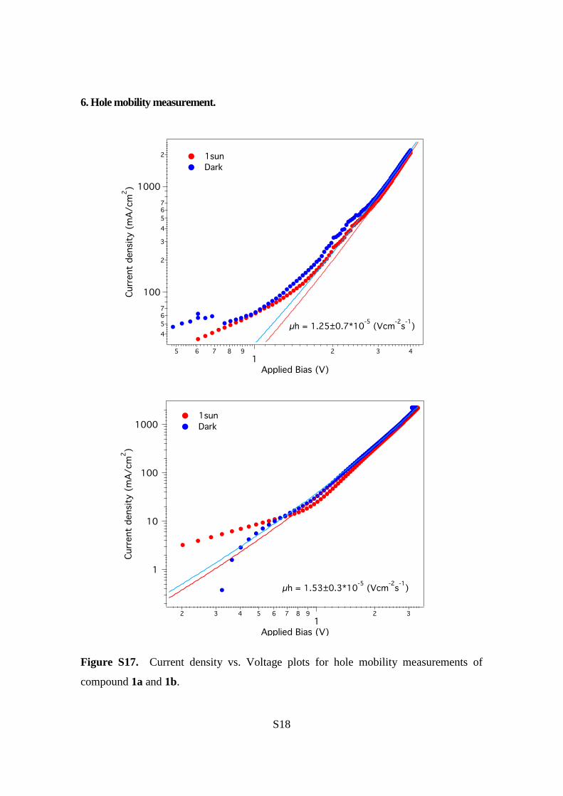
6. Hole mobility measurement.
Figure S17. Current density vs. Voltage plots for hole mobility measurements of
compound 1a and 1b.
S19
The hole mobility was calculated using the Space Charge Limited Current method
(SCLC). The IV curves in Figure S17 were then fitted to the following equation:
JSCLC =9
8emVeff
2
d3exp
0.89b Veff
d
æ
è
çç
ö
ø
÷÷
Where (cm2 V
-1 s
-1) is the mobility coefficient, d (cm) is the film thickness, Veff (V)
is the applied voltage, (cm1/2
V1/2
) is the Poole-Frenkle factor and (0r3) is the
media permittivity.
7. Charge Extraction and Transient Photo-Voltage details.
The Charge Extraction method (CE) consist of a LED ring that apply the desired light
intensity; devices are connected to a DC power supply and a function generator TGP110
to reach a background illumination from 1 sun to dark. The LEDs are typically turned
on for approximately few seconds in order to allow the device to reach steady state
conditions without overheating. Devices are placed before LEDs and held at open
circuit conditions during the illumination, once steady state is reached, the light is
turned off and simultaneously the device is switched to short circuit conditions allowing
it to discharge. The Signal is measured in an oscilloscope that registers the drop in
voltage between a resistance of 50 Ω. Finally, the voltage drop was converted to current
and integrated over time to calculate charge density at every applied bias.
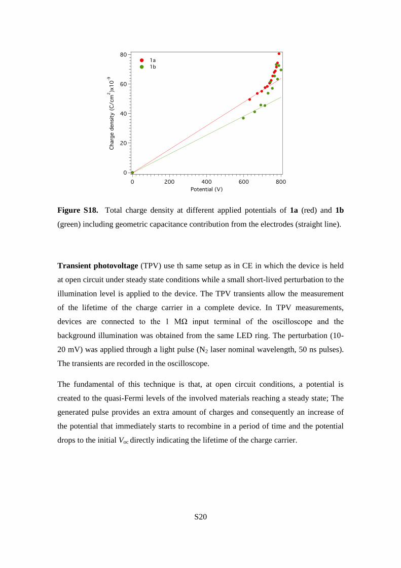
S20
Figure S18. Total charge density at different applied potentials of 1a (red) and 1b
(green) including geometric capacitance contribution from the electrodes (straight line).
Transient photovoltage (TPV) use th same setup as in CE in which the device is held
at open circuit under steady state conditions while a small short-lived perturbation to the
illumination level is applied to the device. The TPV transients allow the measurement
of the lifetime of the charge carrier in a complete device. In TPV measurements,
devices are connected to the 1 MΩ input terminal of the oscilloscope and the
background illumination was obtained from the same LED ring. The perturbation (10-
20 mV) was applied through a light pulse (N2 laser nominal wavelength, 50 ns pulses).
The transients are recorded in the oscilloscope.
The fundamental of this technique is that, at open circuit conditions, a potential is
created to the quasi-Fermi levels of the involved materials reaching a steady state; The
generated pulse provides an extra amount of charges and consequently an increase of
the potential that immediately starts to recombine in a period of time and the potential
drops to the initial Voc directly indicating the lifetime of the charge carrier.