HHM9007R Digital Multimeter - Omega Engineering · 1. Digital Multimeter 2. Test Lead Set (one...
21
e-mail: [email protected] For latest product manuals: www.omegamanual.info Shop online at omega.com ® User’s Guide HHM9007R Digital Multimeter MADE IN TAIWAN μ Ω Ω μ Digital Multimeter HHM9007R
Transcript of HHM9007R Digital Multimeter - Omega Engineering · 1. Digital Multimeter 2. Test Lead Set (one...

e-mail: [email protected] For latest product manuals:
www.omegamanual.info
Shop online at omega.com®
User’s Guide
HHM9007RDigital Multimeter
MADE IN TAIWAN
µ Ω
Ω
µ
DigitalMultimeter
HHM9007R
FOR WARRANTY RETURNS, please have the following information available BEFORE contacting OMEGA:1. Purchase Order number
under which the product was PURCHASED,
2. Model and serial number of the product under warranty, and
3. Repair instructions and/or specific problems relative to the product.
FOR NON-WARRANTY REPAIRS, consult OMEGA for current repair charges. Have the following information available BEFORE contacting OMEGA:1. Purchase Order number to cover
the COST of the repair,2. Model and serial number of the
product, and3. Repair instructions and/or
specific problems relative to the product.
OMEGA’s policy is to make running changes, not model changes, whenever an improvement is possible. This affords our customers the latest in technology and engineering.OMEGA is a registered trademark of OMEGA ENGINEERING, INC.© Copyright 2014 OMEGA ENGINEERING, INC. All rights reserved. This document may not be copied, photocopied, reproduced, translated, or reduced to any electronic medium or machine-readable form, in whole or in part, without the prior written consent of OMEGA ENGINEERING, INC.
RETURN REQUESTS/ INQUIRIESDirect all warranty and repair requests/inquiries to the OMEGA Customer Service Department. BEFORE RETURNING ANY PRODUCT(S) TO OMEGA, PURCHASER MUST OBTAIN AN AUTHORIZED RETURN (AR) NUMBER FROM OMEGA’S CUSTOMER SERVICE DEPARTMENT (IN ORDER TO AVOID PROCESSING DELAYS). The assigned AR number should then be marked on the outside of the return package and on any correspondence. The purchaser is responsible for shipping charges, freight, insurance and proper packaging to prevent breakage in transit.
Servicing North America:U.S.A.: Omega Engineering, Inc., One Omega Drive, P.O. Box 4047, SStamford, CT 06907-0047 USA
Toll-Free: 1-800-826-6342 (USA & Canada only) Customer Service: 1-800-622-2378 (USA & Canada only) Engineering Service: 1-800-872-9436 (USA & Canada only) Tel: (203) 359-1660 Fax: (203) 359-7700 e-mail: [email protected]
For Other Locations Visit omega.com/worldwide
omega.com [email protected]
The information contained in this document is believed to be correct, but OMEGA accepts no liability for any errors it contains, and reserves the right to alter specifications without notice.WARNING: These products are not designed for use in, and should not be used for, human applications.
INTRODUCTIONThis manual contains information and warnings that must be followed to ensure safe operation and retain the meter in safe condition.
WARNINGREAD "SAFETY INFORMATION" BEFORE
USING THE METER.
This Digital Insulation Camp Meter is a handheld 6000-count instrument that is designed for use in the laboratory, field servicing, at home, and any circumstance where high current measurement is required.The clamp meter is built with a design of finger guard which ensures users operating the instrument under a safety situation; a rugged case that is shock resistant and fire-retardant; and electronic overload protection for all functions and ranges. In addition, a carrying case (optional accessory) is available for easy portability of the meter and avoiding damage.
UNPACKING AND INSPECTIONUpon removing your new Digital Insulation Clamp Meter from it’s packing, you should have the following items:
1. Digital Multimeter2. Test Lead Set (one black, one red)3. 9-volt Battery4. Type-K thermocouple5. CD software, USB cable (on RS232 function
model)6. Instruction Manual
SAFETY PRECAUTIONS:The following safety precautions must be observed to ensure maximum personal safety during the operation, service and repair of this meter:
1
2
1. Read these operating instructions thoroughly and
completely before operating your meter. Pay particular
attention to WARNINGS that will inform you of
potentially dangerous procedures. The instructions in
these warnings must be followed.
2. Always inspect your meter, test leads and accessories
for any sign of damage or abnormality before every use.
If any abnormal conditions exist (eg-broken test leads,
cracked cases, display not reading, etc.), do not attempt
to take any measurements.
3. Do not expose the instrument to direct sunlight, extreme
temperature or moisture.
4. Never ground yourself when taking electrical
measurements. Do not touch exposed metal pipes,
outlets, fixtures, etc., which might be at ground potential.
Keep your body isolated from ground by using dry
clothing, rubber shoes, rubber mats, or any approved
insulating material.
5. To avoid electric shock use CAUTION when working
with voltages above DC60V or AC30V rms. Such
voltages pose a shock hazard.
6. Never exceed the maximum allowable input value of any
function when taking a measurement. Refer to the
specifications for maximum inputs.
7. Never touch exposed wiring, connections or any live
circuit when attempting to take measurements.
8. Do not attempt to operate this instrument in an
explosive atmosphere (i.e. in the presence of flammable
gases or fumes, vapor or dust).
9. When testing for the presence of voltage, make sure the
voltage function is operating properly by reading a
known voltage in that function before assuming that a
zero reading indicates a no-voltage condition. Always
test your meter before and after taking measurements
on a known live circuit.
3
SAFETY INFORMATION
CleaningWipe the case with a damp cloth and mild
detergent. Do not use abrasives or solvents. Dirt or
moisture in the terminals can affect readings.
Safety: Conforms to IEC/EN 61010-1, IEC/EN
61010-2-033, CAT III 1000V, CAT IV 600V,
Class II, Pollution degree 2 Indoor use.
CAT III: Is for measurements performed in the
building installation.
CAT IV: Is for measurements performed at the
source of the low-voltage installation.
EMC: Conforms to EN 61326-1.
The symbols used on this instrumentare:
Dangerous voltage.
Caution, refer to accompanying
documents
Equipment protected throughout by
Double insulation (Class II)
Alternating current
Direct current
Ground
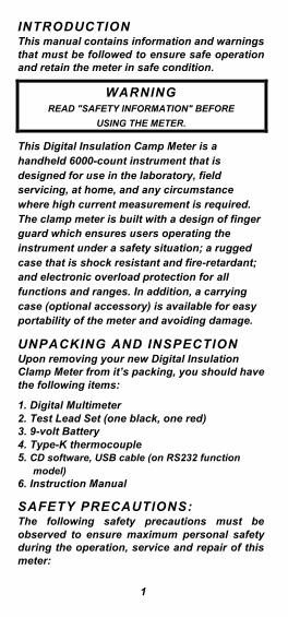
INSTRUMENT LAYOUT
4
16
11
1098
7
6
2
1
(6000 or RS232)
15
14
13
12
5
4
3
cal>2s±
+
+
ns
mV+
V+
mV
MAX 400mA
TRUE RMS AC+DC
DigitalMultimeter
HHM9007R
30VMAX
%
AUTO POWER OFF
CAT.III
V
Hz %
SHIFT
C F
K-Type+
CATIV 600V
0 10 20 5030 40 60
HOLDMIN/MAXRANGE REL
COMmAA20A
20A/30secFUSED
MAX
FUSED
V
750V
MAX1000V
CATIII 1000V
5
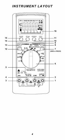
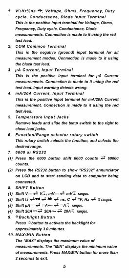
1. V Hz%ns , Voltage, Ohms, Frequency, Duty
cycle, Conductance, Diode Input Terminal
This is the positive input terminal for Voltage, Ohms,
Frequency, Duty cycle, Conductance, Diode
measurements. Connection is made to it using the red
test lead.
2. COM Common Terminal
This is the negative (ground) input terminal for all
measurement modes. Connection is made to it using
the black test lead.
3. µA Current, Input Terminal
This is the positive input terminal for µA Current
measurements. Connection is made to it using the red
test lead. Input warning detects wrong.
4. mA/20A Current, Input Terminal
This is the positive input terminal for mA/20A Current
measurement. Connection is made to it using the red
test lead.
5. Temperature Input Jacks
Remove leads and slide the temp switch to the right to
close lead jacks.
6. Function/Range selector rotary switch
This rotary switch selects the function, and selects the
desired range.
7. 6000 or RS232
(1) Press the 6000 button shift 6000 counts 60000
counts.
(2) Press the RS232 button to show "RS232" annunciator
on LCD and to start sending data to computer being
connected.
8. SHIFT Button
(1) Shift V V + , mV mV + ranges.
(2) Shift ns, C °F, Hz % ranges.
(3) Shift µA + ranges.
(4) Shift 20A 20A 20A + ranges.
9. Backlight Button
Press button to activate the backlight for
approximately 3.0 minutes.
10. MAX/MIN Button
The "MAX" displays the maximum value of
measurements. The "MIN" displays the minimum value
of measurements. Press MAX/MIN button for more than
2 seconds to exit.
11. HOLD Button
(1) Press [HOLD] button to toggle in and out of the Data
Hold mode. In the data hold mode, the "HOLD
annunciator is displayed and the last reading is held on
the display.
(2) Press [HOLD] button again to release the hold and
current readings are once again displayed.
12. HFR Button
Shift "HFR1" (High Frequency reject: > 1kHz)
"HFR2" (High Frequency reject: > 100kHz), on
AC Volts range.
13. PEAK± cal>2s Button
(1) Record the peak+ or peak- value in a measurement. It is
usable with AC voltage, AC current measurements. If
the pressed time >2 sec, the PEAK function will enter to
calibration mode, the LCD will show "CAL" and the
internal buffer will remember the internal op off set
voltage then back to the measure mode.
(2) Press PEAK± button for more than 2 seconds to exit.
(3) Response time: more than 1ms.
14. REL Button
(1) Press (REL ) button to enter the Relative mode. The
" " appears to indicate that the relative mode is
activated and non-zero number is offset and saved. The
flashing " " appears and the offset value displays at
the same time for comparison with the reading of
measurement.
(2) After finishing the measurement, press (REL ) button
for more than 2 seconds to exit.
15. RANGE Button
(1) Press (RANGE) button to select the Manual Range
mode (The meter remains in the range it was in when
manual ranging was selected).
(2) In the Manual Range mode, each time you press
(RANGE) button, the range (and the input range
annunciator) increments, and a new value is displayed.
To exit the Manual Range mode and return to
autoranging, press and hold down (RANGE) button for
2 seconds.
16. Display
The display indicates the measured value of a signal,
function mode, and annunciator.
6
7
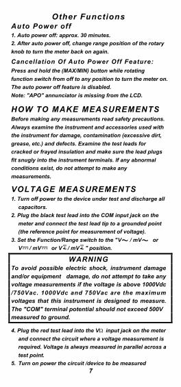
Other FunctionsAuto Power off1. Auto power off: approx. 30 minutes.
2. After auto power off, change range position of the rotary
knob to turn the meter back on again.
Cancellation Of Auto Power Off Feature:Press and hold the (MAX/MIN) button while rotating
function switch from off to any position to turn the meter on.
The auto power off feature is disabled.
Note: "APO" annunciator is missing from the LCD.
HOW TO MAKE MEASUREMENTSBefore making any measurements read safety precautions.
Always examine the instrument and accessories used with
the instrument for damage, contamination (excessive dirt,
grease, etc.) and defects. Examine the test leads for
cracked or frayed insulation and make sure the lead plugs
fit snugly into the instrument terminals. If any abnormal
conditions exist, do not attempt to make any
measurements.
VOLTAGE MEASUREMENTS1. Turn off power to the device under test and discharge all
capacitors.
2. Plug the black test lead into the COM input jack on the
meter and connect the test lead tip to a grounded point
(the reference point for measurement of voltage).
3. Set the Function/Range switch to the "V / mV or
V / mV or V + / mV + " position.
WARNINGTo avoid possible electric shock, instrument damage
and/or equipment damage, do not attempt to take any voltage measurements if the voltage is above 1000Vdc
/750Vac. 1000Vdc and 750Vac are the maximumvoltages that this instrument is designed to measure.
The "COM" terminal potential should not exceed 500V measured to ground.
4. Plug the red test lead into the V input jack on the meter
and connect the circuit where a voltage measurement is
required. Voltage is always measured in parallel across a
test point.
5. Turn on power the circuit /device to be measured
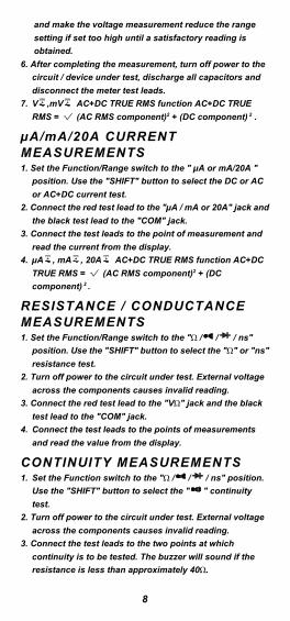
and make the voltage measurement reduce the range
setting if set too high until a satisfactory reading is
obtained.
6. After completing the measurement, turn off power to the
circuit / device under test, discharge all capacitors and
disconnect the meter test leads.
7. V + ,mV + AC+DC TRUE RMS function AC+DC TRUE
RMS = (AC RMS component)2 + (DC component) 2 .
µA/mA/20A CURRENTMEASUREMENTS1. Set the Function/Range switch to the " µA or mA/20A "
position. Use the "SHIFT" button to select the DC or AC
or AC+DC current test.
2. Connect the red test lead to the "µA / mA or 20A" jack and
the black test lead to the "COM" jack.
3. Connect the test leads to the point of measurement and
read the current from the display.
4. µA + , mA + , 20A + AC+DC TRUE RMS function AC+DC
TRUE RMS = (AC RMS component)2 + (DC
component) 2 .
RESISTANCE / CONDUCTANCEMEASUREMENTS1. Set the Function/Range switch to the " / / / ns"
position. Use the "SHIFT" button to select the " " or "ns"
resistance test.
2. Turn off power to the circuit under test. External voltage
across the components causes invalid reading.
3. Connect the red test lead to the "V " jack and the black
test lead to the "COM" jack.
4. Connect the test leads to the points of measurements
and read the value from the display.
CONTINUITY MEASUREMENTS1. Set the Function switch to the " / / / ns" position.
Use the "SHIFT" button to select the " " continuity
test.
2. Turn off power to the circuit under test. External voltage
across the components causes invalid reading.
3. Connect the test leads to the two points at which
continuity is to be tested. The buzzer will sound if the
resistance is less than approximately 40 .
8
9
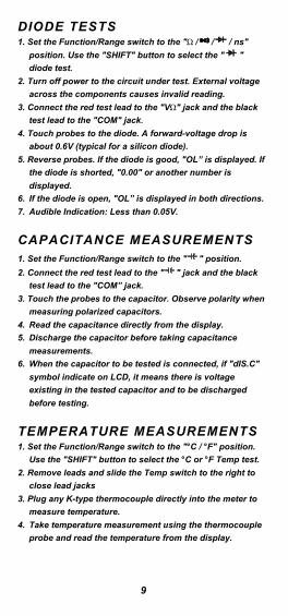
DIODE TESTS1. Set the Function/Range switch to the " / / / ns"
position. Use the "SHIFT" button to select the " "
diode test.
2. Turn off power to the circuit under test. External voltage
across the components causes invalid reading.
3. Connect the red test lead to the "V " jack and the black
test lead to the "COM" jack.
4. Touch probes to the diode. A forward-voltage drop is
about 0.6V (typical for a silicon diode).
5. Reverse probes. If the diode is good, "OL” is displayed. If
the diode is shorted, "0.00" or another number is
displayed.
6. If the diode is open, "OL” is displayed in both directions.
7. Audible Indication: Less than 0.05V.
CAPACITANCE MEASUREMENTS1. Set the Function/Range switch to the " " position.
2. Connect the red test lead to the " " jack and the black
test lead to the "COM” jack.
3. Touch the probes to the capacitor. Observe polarity when
measuring polarized capacitors.
4. Read the capacitance directly from the display.
5. Discharge the capacitor before taking capacitance
measurements.
6. When the capacitor to be tested is connected, if "dIS.C"
symbol indicate on LCD, it means there is voltage
existing in the tested capacitor and to be discharged
before testing.
TEMPERATURE MEASUREMENTS1. Set the Function/Range switch to the "°C / °F" position.
Use the "SHIFT" button to select the °C or °F Temp test.
2. Remove leads and slide the Temp switch to the right to
close lead jacks
3. Plug any K-type thermocouple directly into the meter to
measure temperature.
4. Take temperature measurement using the thermocouple
probe and read the temperature from the display.
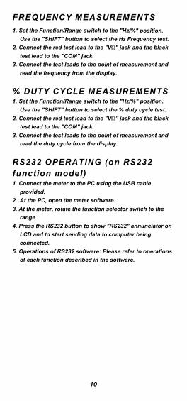
FREQUENCY MEASUREMENTS
1. Set the Function/Range switch to the "Hz/%" position.
Use the "SHIFT" button to select the Hz Frequency test.
2. Connect the red test lead to the "V " jack and the black
test lead to the "COM" jack.
3. Connect the test leads to the point of measurement and
read the frequency from the display.
% DUTY CYCLE MEASUREMENTS1. Set the Function/Range switch to the "Hz/%" position.
Use the "SHIFT" button to select the % duty cycle test.
2. Connect the red test lead to the "V ” jack and the black
test lead to the "COM" jack.
3. Connect the test leads to the point of measurement and
read the duty cycle from the display.
RS232 OPERATING (on RS232function model)1. Connect the meter to the PC using the USB cable
provided.
2. At the PC, open the meter software.
3. At the meter, rotate the function selector switch to the
range
4. Press the RS232 button to show "RS232" annunciator on
LCD and to start sending data to computer being
connected.
5. Operations of RS232 software: Please refer to operations
of each function described in the software.
10
11
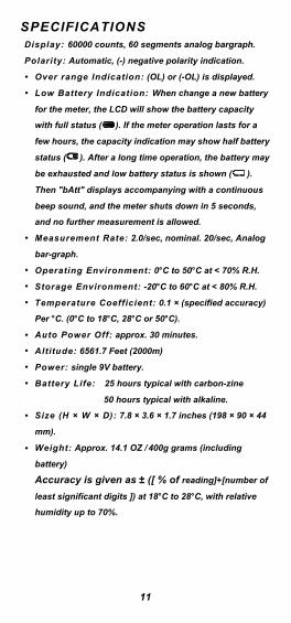
SPECIFICATIONSDisplay: 60000 counts, 60 segments analog bargraph.
Polarity: Automatic, (-) negative polarity indication.
O•
•
•
•
•
•
•
•
•
•
•
•
ver range Indication: (OL) or (-OL) is displayed.
Low Battery Indication: When change a new battery
for the meter, the LCD will show the battery capacity
with full status ( ). If the meter operation lasts for a
few hours, the capacity indication may show half battery
status ( ). After a long time operation, the battery may
be exhausted and low battery status is shown ( ).
Then "bAtt" displays accompanying with a continuous
beep sound, and the meter shuts down in 5 seconds,
and no further measurement is allowed.
Measurement Rate: 2.0/sec, nominal. 20/sec, Analog
bar-graph.
Operating Environment: 0°C to 50°C at < 70% R.H.
Storage Environment: -20°C to 60°C at < 80% R.H.
Temperature Coefficient: 0.1 (specified accuracy)
Per °C. (0°C to 18°C, 28°C or 50°C).
Auto Power Off: approx. 30 minutes.
Altitude: 6561.7 Feet (2000m)
Power: single 9V battery.
Battery Life: 25 hours typical with carbon-zine
50 hours typical with alkaline.
Size (H W D): 7.8 3.6 1.7 inches (198 90 44
mm).
Weight: Approx. 14.1 OZ / 400g grams (including
battery)
Accuracy is given as ± ([ % of reading]+[number of
least significant digits ]) at 18°C to 28°C, with relative
humidity up to 70%.
12
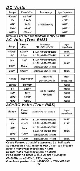
DC VoltsRange Resolution Accuracy lnput lmpedance
600mV 0.01mV
± (0.08% red+5d)
10M
6V 0.1mV 11M
60V 1mV 10M
600V 10mV 10M
1000V 100mV 10M
Overload protection: 1000V DC or 750V AC RMS
AC Volts (True RMS)
RangeResolu
-tionAccuracy
(45~2kHz )/HFR2lnput
lmpedance
600mV 0.01mV ± (1.0% red+20d) 45~500Hz
± (1.5% red+20d) 500~1kHz
10M
6V 0.1mV 11M
60V 1mV ± (1.0% red+20d) 45~500Hz
± (1.5% red+20d) 500~1kHz
± (2.0% red+20d) 1k~2kHz
10M600V 10mV
750V 100mV ± (2.0% red+20d) 45~1kHz 10M
Range ResolutionAccuracy
(45~60Hz)/HFR1
lnput
lmpedance
600mV 0.01mV
± (2.0% red+20d)
45~60Hz
10M
6V 0.1mV 11M
60V 1mV 10M
600V 10mV 10M
750V 100mV 10M
AC+DC Volts (True RMS)
Range Reso-lution
Accuracy ( 45~2kHz ) lnputlmpedance
600mV 0.01m
V
± (1.5% red+30d) 45~500Hz
± (2.0% red+30d) 500~1kHz
10M
6V 0.1mV 11M
60V 1mV ± (1.5% red+30d) 45~500Hz
± (2.0% red+30d) 500~1kHz
± (2.5% red+30d) 1k~2kHz
10M600V 10mV
750V 100m
V
± (2.5% red+30d) 45~1kHz 10M
Crest Factor: 3 at full scale and 6 at half scaleAC coupled true RMS specified from 2% to 100% of rangeHFR1: High Frequency reject: > 1kHzHFR2: High Frequency reject: > 100kHzPeak Hold Accuracy: ± (3.0% rdg + 500 dgts)45~500Hz on AC 60V to 750V rangesOverload protection: 1000V DC or 750V AC RMS
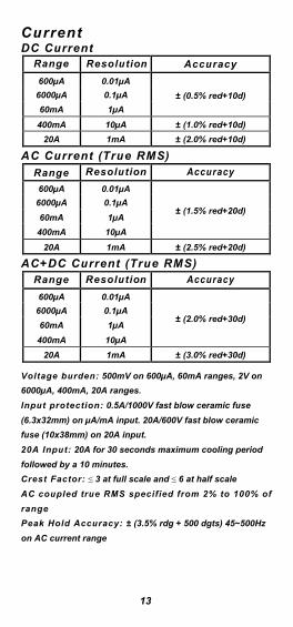
CurrentDC Current
Range Resolution Accuracy
600µA 0.01µA
± (0.5% red+10d)6000µA 0.1µA
60mA 1µA
400mA 10µA ± (1.0% red+10d)
20A 1mA ± (2.0% red+10d)
AC Current (True RMS)
Range Resolution Accuracy
600µA 0.01µA
± (1.5% red+20d)6000µA 0.1µA
60mA 1µA
400mA 10µA
20A 1mA ± (2.5% red+20d)
AC+DC Current (True RMS)Range Resolution Accuracy
600µA 0.01µA
± (2.0% red+30d)6000µA 0.1µA
60mA 1µA
400mA 10µA
20A 1mA ± (3.0% red+30d)
Voltage burden: 500mV on 600µA, 60mA ranges, 2V on
6000µA, 400mA, 20A ranges.
Input protection: 0.5A/1000V fast blow ceramic fuse
(6.3x32mm) on µA/mA input. 20A/600V fast blow ceramic
fuse (10x38mm) on 20A input.
20A Input: 20A for 30 seconds maximum cooling period
followed by a 10 minutes.
Crest Factor: 3 at full scale and 6 at half scale
AC coupled true RMS specified from 2% to 100% of
range
Peak Hold Accuracy: ± (3.5% rdg + 500 dgts) 45~500Hz
on AC current range
13
14
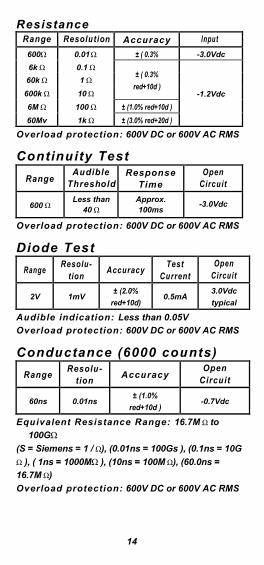
ResistanceRange Resolution Accuracy lnput
600 0.01 ± ( 0.3%
red+20d )
-3.0Vdc
6k 0.1± ( 0.3%
red+10d )-1.2Vdc
60k 1
600k 10
6M 100 ± (1.0% red+10d )
60Mv 1k ± (3.0% red+20d )
Overload protection: 600V DC or 600V AC RMS
Continuity Test
RangeAudible
ThresholdResponse
TimeOpen
Circuit
600Less than
40Approx. 100ms
-3.0Vdc
Overload protection: 600V DC or 600V AC RMS
Diode Test
RangeResolu-
tionAccuracy
TestCurrent
OpenCircuit
2V 1mV± (2.0%
red+10d)0.5mA
3.0Vdc
typical
Audible indication: Less than 0.05V
Overload protection: 600V DC or 600V AC RMS
Conductance (6000 counts)
RangeResolu-
tionAccuracy
OpenCircuit
60ns 0.01ns± (1.0%
red+10d )-0.7Vdc
Equivalent Resistance Range: 16.7M to
100G
(S = Siemens = 1 / ), (0.01ns = 100Gs ), (0.1ns = 10G
), ( 1ns = 1000M ), (10ns = 100M ), (60.0ns =
16.7M )
Overload protection: 600V DC or 600V AC RMS
15
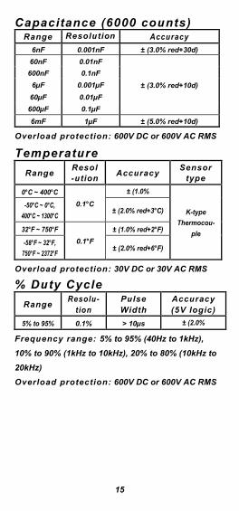
Capacitance (6000 counts)Range Resolution Accuracy
6nF 0.001nF ± (3.0% red+30d)
60nF 0.01nF
± (3.0% red+10d)
600nF 0.1nF
6µF 0.001µF
60µF 0.01µF
600µF 0.1µF
6mF 1µF ± (5.0% red+10d)
Overload protection: 600V DC or 600V AC RMS
Temperature
RangeResol-ution
AccuracySensor
type
0°C ~ 400°C
0.1°C
± (1.0%
red+1°C )K-type
Thermocou-
ple
-50°C ~ 0°C,
400°C ~ 1300°C± (2.0% red+3°C)
32°F ~ 750°F
0.1°F
± (1.0% red+2°F)
-58°F ~ 32°F,
750°F ~ 2372°F± (2.0% red+6°F)
Overload protection: 30V DC or 30V AC RMS
% Duty Cycle
RangeResolu-
tionPulseWidth
Accuracy(5V logic)
5% to 95% 0.1% > 10µs ± (2.0%
red+10d )Frequency range: 5% to 95% (40Hz to 1kHz),
10% to 90% (1kHz to 10kHz), 20% to 80% (10kHz to
20kHz)
Overload protection: 600V DC or 600V AC RMS
16
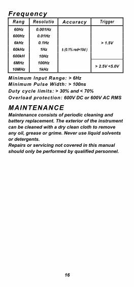
FrequencyRang
eResolutio
nAccuracy Trigger
Leve160Hz 0.001Hz
± (0.1% red+10d )
> 1.5V
600Hz 0.01Hz
6kHz 0.1Hz
60kHz 1Hz
600kH
z
10Hz
6MHz 100Hz> 2.5V <5.0V
10MHz 1kHz
Minimum lnput Range: > 6HzMinimum Pulse Width: > 100ns
Duty cycle limits: > 30% and < 70%
Overload protection: 600V DC or 600V AC RMS
MAINTENANCEMaintenance consists of periodic cleaning andbattery replacement. The exterior of the instrument can be cleaned with a dry clean cloth to removeany oil, grease or grime. Never use liquid solvents or detergents.Repairs or servicing not covered in this manual should only be performed by qualified personnel.
17
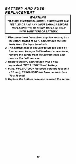
BATTERY AND FUSEREPLACEMENT
WARNINGTO AVOID ELECTRICAL SHOCK, DISCONNECT THE
TEST LEADS AND ANY INPUT SIGNALS BEFORE
REPLACING THE BATTERY. REPLACE ONLY WITH SAME TYPE OF BATTERY.
1. Disconnect test leads from any live source, turn the rotary switch to OFF, and remove the test leads from the input terminals.
2. The bottom case is secured to the top case by four screws. Using a Phillips-head screwdriver, remove the screw from the bottom case and remove the bottom case.
3. Remove battery and replace with a new equivalent "NEDA 1604" 9-volt battery.
4. Fuse: F1/0.5A/1000V fast blow ceramic fuse (6.3x 32 mm); F2/20A/600V fast blow ceramic fuse (10 x 38 mm).
5. Replace the bottom case and reinstall the screw.

WARRANTY/DISCLAIMEROMEGA ENGINEERING, INC. warrants this unit to be free of defects in materials and workmanship for a period of 13 months from date of purchase. OMEGA’s Warranty adds an additional one (1) month grace period to the normal one (1) year product warranty to cover handling and shipping time. This ensures that OMEGA’s customers receive maximum coverage on each product. If the unit malfunctions, it must be returned to the factory for evaluation. OMEGA’s Customer Service Department will issue an Authorized Return (AR) number immediately upon phone or written request. Upon examination by OMEGA, if the unit is found to be defective, it will be repaired or replaced at no charge. OMEGA’s WARRANTY does not apply to defects resulting from any action of the purchaser, including but not limited to mishandling, improper interfacing, operation outside of design limits, improper repair, or unauthorized modification. This WARRANTY is VOID if the unit shows evidence of having been tampered with or shows evidence of having been damaged as a result of excessive corrosion; or current, heat, moisture or vibration; improper specification; misapplication; misuse or other operating conditions outside of OMEGA’s control. Components in which wear is not warranted, include but are not limited to contact points, fuses, and triacs.OMEGA is pleased to offer suggestions on the use of its various products. However, OMEGA neither assumes responsibility for any omissions or errors nor assumes liability for any damages that result from the use of its products in accordance with information provided by OMEGA, either verbal or written. OMEGA warrants only that the parts manufactured by the company will be as specified and free of defects. OMEGA MAKES NO OTHER WARRANTIES OR REPRESENTATIONS OF ANY KIND WHATSOEVER, EXPRESSED OR IMPLIED, EXCEPT THAT OF TITLE, AND ALL IMPLIED WARRANTIES INCLUDING ANY WARRANTY OF MERCHANTABILITY AND FITNESS FOR A PARTICULAR PURPOSE ARE HEREBY DISCLAIMED. LIMITATION OF LIABILITY: The remedies of purchaser set forth herein are exclusive, and the total liability of OMEGA with respect to this order, whether based on contract, warranty, negligence, indemnification, strict liability or otherwise, shall not exceed the purchase price of the component upon which liability is based. In no event shall OMEGA be liable for consequential, incidental or special damages.CONDITIONS: Equipment sold by OMEGA is not intended to be used, nor shall it be used: (1) as a “Basic Component” under 10 CFR 21 (NRC), used in or with any nuclear installation or activity; or (2) in medical applications or used on humans. Should any Product(s) be used in or with any nuclear installation or activity, medical application, used on humans, or misused in any way, OMEGA assumes no responsibility as set forth in our basic WARRANTY/ DISCLAIMER language, and, additionally, purchaser will indemnify OMEGA and hold OMEGA harmless from any liability or damage whatsoever arising out of the use of the Product(s) in such a manner.
TEMPERATUREMU Thermocouple, RTD & Thermistor Probes, Connectors,
Panels & AssembliesMU Wire: Thermocouple, RTD & ThermistorMU Calibrators & Ice Point ReferencesMU Recorders, Controllers & Process MonitorsMU Infrared PyrometersPRESSURE, STRAIN AND FORCEMU Transducers & Strain GagesMU Load Cells & Pressure GagesMU Displacement TransducersMU Instrumentation & AccessoriesFLOW/LEVELMU Rotameters, Gas Mass Flowmeters & Flow ComputersMU Air Velocity IndicatorsMU Turbine/Paddlewheel SystemsMU Totalizers & Batch ControllerspH/CONDUCTIVITYMU pH Electrodes, Testers & AccessoriesMU Benchtop/Laboratory MetersMU Controllers, Calibrators, Simulators & PumpsMU Industrial pH & Conductivity EquipmentDATA ACQUISITIONMU Data Acquisition & Engineering SoftwareMU Communications-Based Acquisition SystemsMU Plug-in Cards for Apple, IBM & CompatiblesMU Data Logging SystemsMU Recorders, Printers & PlottersHEATERSMU Heating CableMU Cartridge & Strip HeatersMU Immersion & Band HeatersMU Flexible HeatersMU Laboratory HeatersENVIRONMENTAL MONITORING AND CONTROLMU Metering & Control InstrumentationMU RefractometersMU Pumps & TubingMU Air, Soil & Water MonitorsMU Industrial Water & Wastewater TreatmentMU pH, Conductivity & Dissolved Oxygen Instruments
Where Do I Find Everything I Need for Process Measurement
and Control? OMEGA…Of Course!
Shop online at omega.com sm
M5415/0714


![FM- Frequency Modulation PM - Phase · PDF file7 PM and digital modulation [] [] s p where 2 is the pk-pk phase change in one symbol duration, T For Digital signals the modulation](https://static.fdocument.org/doc/165x107/5abcf34a7f8b9a567c8e631b/fm-frequency-modulation-pm-phase-pm-and-digital-modulation-s-p-where-2.jpg)