The 2 charged particles analyzer: All-sky camera concept ...
page 1
108A Harmonic Power Analyzer
Swiss Made
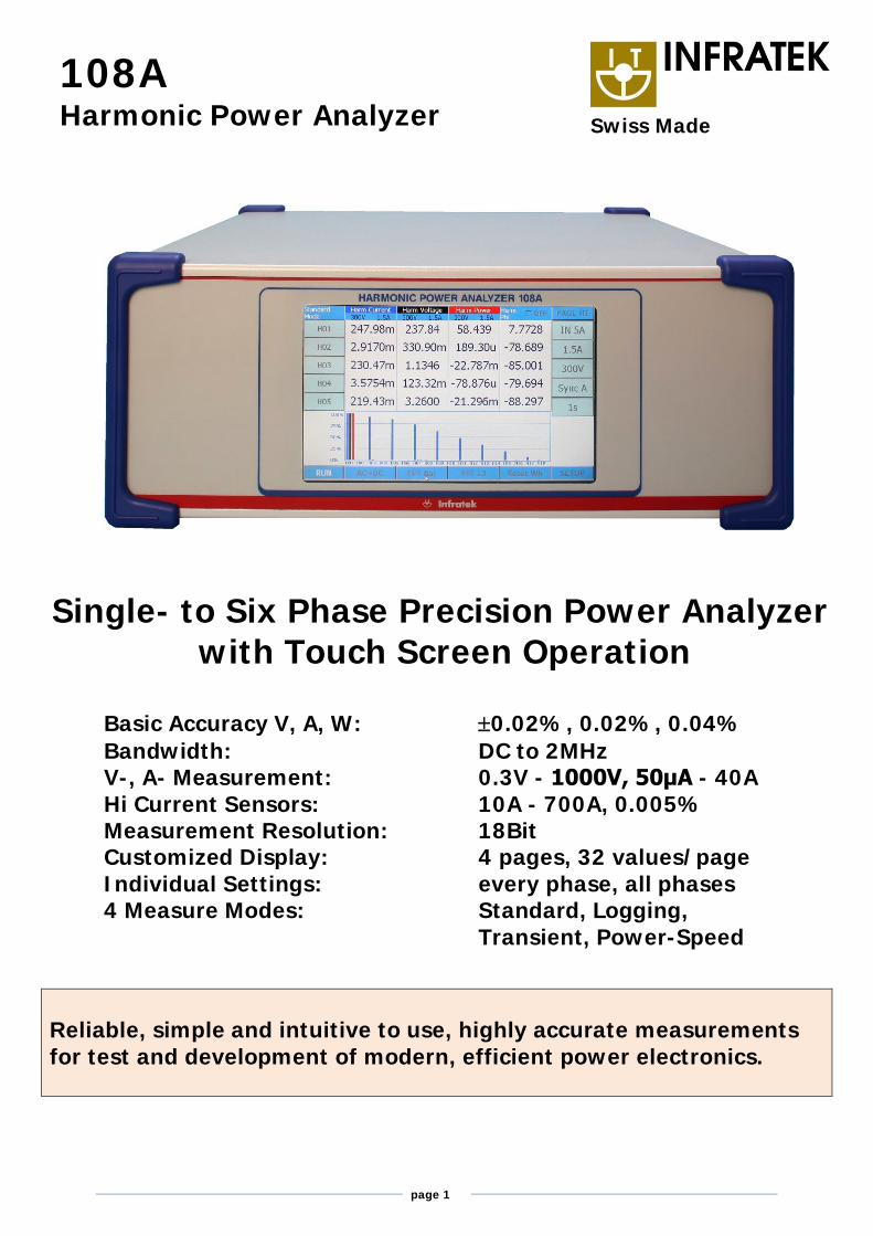
Single- to Six Phase Precision Power Analyzer with Touch Screen Operation
Basic Accuracy V, A, W: 0.02%, 0.02%, 0.04% Bandwidth: DC to 2MHz V-, A- Measurement: 0.3V - 1000V, 50μA - 40A Hi Current Sensors: 10A - 700A, 0.005% Measurement Resolution: 18Bit Customized Display: 4 pages, 32 values/page Individual Settings: every phase, all phases 4 Measure Modes: Standard, Logging, Transient, Power-Speed
Reliable, simple and intuitive to use, highly accurate measurements for test and development of modern, efficient power electronics.
page 2
The MODEL 108A UNIVERSAL HIGH PRECISION POWER ANALYZER measures 280 electrical quantities on every phase. Energies, harmonics, motor- and transformer values, power sums, power ratios, analog- and frequency inputs can be displayed, or read via interface at any time
FEATURES - Available as 1-, 2-, 3-, 4-, 5-, 6-phase instrument - 18 bit resolution. High accuracy at 10% full scale - Simple to operate, most settings in 2 steps (2 touches) - Extremely fast data transfer; up to 3400 values per seconds - 4 current inputs: 1mA–1A, 15mA–5A, 1A–50A, Shunt - Optional interfaces: Ethernet, RS-232 / USB, IEEE-488 - Interface commands for fast data transmission - Optional high precision, broadband, current sensors 0.004% - 6 analog inputs and 2 frequency inputs, 12 analog outputs - Highest precision available: 0.02% + 0.02% range
- Wide angle, touch-screen TFT display (800 x 480 pixels) - Standard-, Logging-, Transient-, Power-Speed measure modes - High DC precision for solar applications - Voltage Ranges: 0.3V to 1000V - Two optional operating softwares under Windows - Software to read data from four 108A-6 - Simple servicing, modular concept, pre-calibrated inputs - 4G Byte Memory for storing measurement data - Reasonably priced by virtue of smart design - Individual settings for every phase and all phases
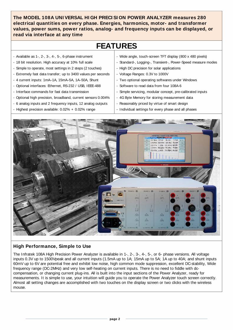
High Performance, Simple to Use The Infratek 108A High Precision Power Analyzer is available in 1-, 2-, 3-, 4-, 5-, or 6- phase versions. All voltage inputs 0.3V up to 1500Vpeak and all current inputs (1.5mA up to 1A; 15mA up to 5A; 1A up to 40A; and shunt inputs 60mV up to 6V are potential free and exhibit low noise, high common mode suppression, excellent DC-stability, Wide frequency range (DC-2MHz) and very low self-heating on current inputs. There is no need to fiddle with dc-compensation, or changing current plug-ins. All is built into the input sections of the Power Analyzer, ready for measurements. It is simple to use, your intuition will guide you to operate the Power Analyzer touch screen correctly. Almost all setting changes are accomplished with two touches on the display screen or two clicks with the wireless mouse.
page 3
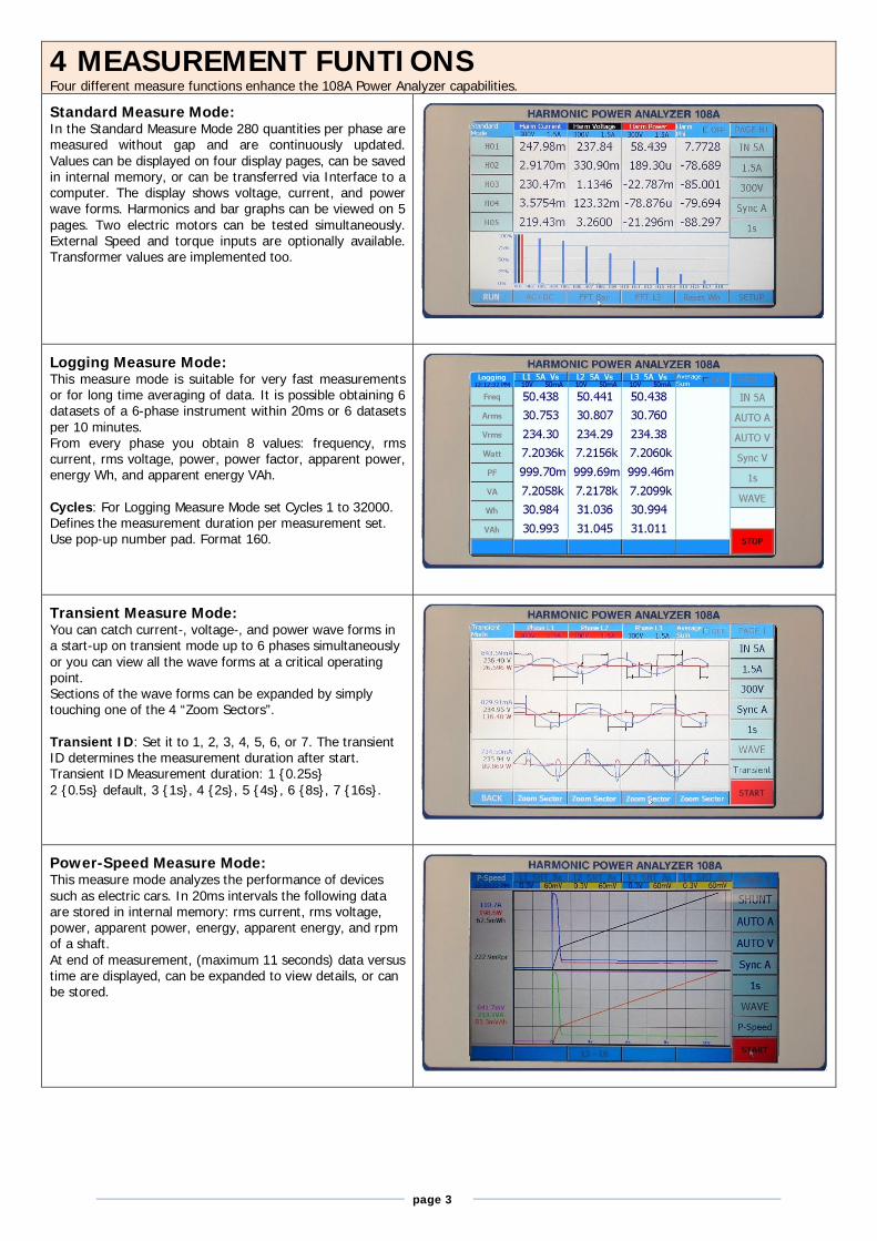
4 MEASUREMENT FUNTIONS Four different measure functions enhance the 108A Power Analyzer capabilities. Standard Measure Mode: In the Standard Measure Mode 280 quantities per phase are measured without gap and are continuously updated. Values can be displayed on four display pages, can be saved in internal memory, or can be transferred via Interface to a computer. The display shows voltage, current, and power wave forms. Harmonics and bar graphs can be viewed on 5 pages. Two electric motors can be tested simultaneously. External Speed and torque inputs are optionally available. Transformer values are implemented too.
Logging Measure Mode: This measure mode is suitable for very fast measurements or for long time averaging of data. It is possible obtaining 6 datasets of a 6-phase instrument within 20ms or 6 datasets per 10 minutes. From every phase you obtain 8 values: frequency, rms current, rms voltage, power, power factor, apparent power, energy Wh, and apparent energy VAh. Cycles: For Logging Measure Mode set Cycles 1 to 32000. Defines the measurement duration per measurement set. Use pop-up number pad. Format 160.
Transient Measure Mode: You can catch current-, voltage-, and power wave forms in a start-up on transient mode up to 6 phases simultaneously or you can view all the wave forms at a critical operating point. Sections of the wave forms can be expanded by simply touching one of the 4 “Zoom Sectors”. Transient ID: Set it to 1, 2, 3, 4, 5, 6, or 7. The transient ID determines the measurement duration after start. Transient ID Measurement duration: 1 {0.25s} 2 {0.5s} default, 3 {1s}, 4 {2s}, 5 {4s}, 6 {8s}, 7 {16s}.
Power-Speed Measure Mode: This measure mode analyzes the performance of devices such as electric cars. In 20ms intervals the following data are stored in internal memory: rms current, rms voltage, power, apparent power, energy, apparent energy, and rpm of a shaft. At end of measurement, (maximum 11 seconds) data versus time are displayed, can be expanded to view details, or can be stored.
page 4
APPLICATIONS
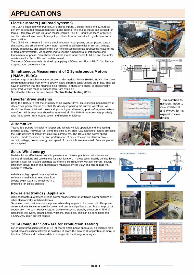
Electric Motors (Railroad systems) The 108A-6 equipped with (Option03) 6 analog inputs, 2 digital inputs and 12 outputs perform all required measurements for motor testing. The analog inputs can be used for torque-, temperature and vibration measurements. The TTL inputs for speed or torque, and the external synchronization input per phase from an encoder to synchronize to the pole position. The 108A-6 can measure 2 motors simultaneously: input power, output power, torque, slip, speed, and efficiency of every motor, as well as all harmonics of current, voltage, power, impedance, and phase angle. For none sinusoidal signals (trapezoidal wave-forms or frequency inverters), we recommend to use the fundamental of impedance and fundamental of phase. From these values the motor inductances L, Ld, Lq and the motor resistances R = Rm + Rdc can be determined. The motor DC-resistance is obtained by applying a DC-current: Rdc = Pdc / I2dc. Rm is a magnetization dependent loss. Simultaneous Measurement of 2 Synchronous Motors (PMSM, BLDC) A wide range of synchronous motors are on the market (PMSM, IPMSM, BLDC). The power consumption ranges from mW to 500kW. Many different constructions are in use. They all have in common that the magnetic field rotation (2 phase or 3 phase) is electronically generated. A wide range of speeds (rpm) are available. See also the Infratek documentation: Electric Motor Testing (PDF)
Inverter drive systems Using the 108A-6 to test the efficiency of an inverter drive, simultaneous measurement of all electrical parameters is essential. By visually inspecting the current waveform, we should see three individual currents all producing an alternating positive/negative pattern waveform. All three phases should be symmetrical. The 108A-6 measures very precisely total input power, total output power and inverter efficiency! Automotive Testing fuel pumps is crucial for proper and reliable vehicle operation and long lasting product quality. Individual fuel pump tests like Start-Stop, Low-Speed/Full-Speed are used; the 108A delivers all important electrical parameters. The 108A in the power-speed measure mode measures the start performance of an electric car. In 20ms intervals current, voltage, power, energy, and speed of the vehicle are measured. Data are plotted versus speed.
Solar/Wind energy Decisive for an effective technical implementation of solar plants and wind farms are various simulations and correlations for each location. In these tests, exactly defined levels are simulated. All relevant electrical parameters like frequency, voltage, current, power, efficiency, power factor and energies are measured by the 108A and can be read via computer software. A dedicated high speed data acquisition software is available to read data from several 108A. Data are combined in a single file for simple analysis.
Power electronics / Appliance Wide bandwidth guarantees precise power measurement of switching power supplies or other electronically switched devices. Some electronic devices consume power when they appear to be turned off. This power consumption is known as standby power and can be a significant contribution to product energy use. The 108A Power Analyzer precisely measure standby power on all kind of appliances like ovens, ceramic hobs, washers, dryers etc. This can be done using the 1.5mA/5mA/15mA current ranges. 108A Computer Software for Production Testing For efficient production testing of 12 (or more) single phase apparatus, a dedicated high speed data acquisition software is available. It reads the data of 12 apparatus (or more) in less than 100ms and combines data in a single file for storage or analysis.
108A switched to transient mode to view inverter U, I, and P wave forms; expand to view details.
page 5
Specifications
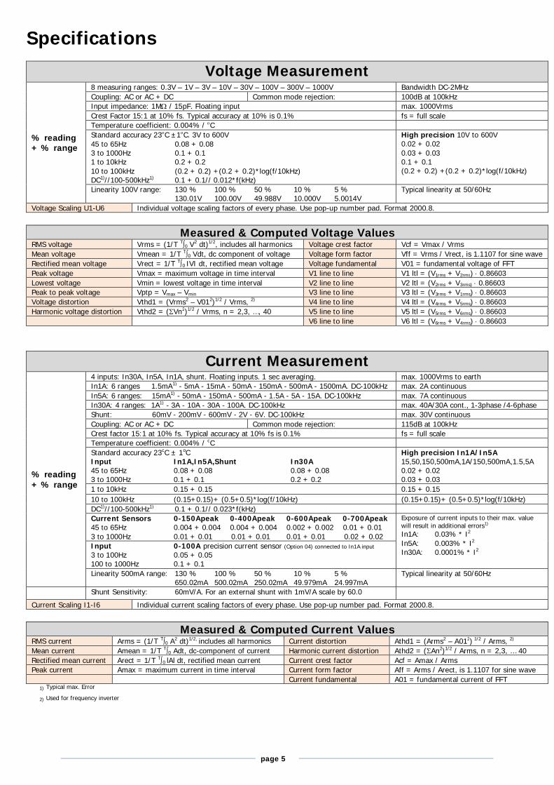
Voltage Measurement
% reading + % range
8 measuring ranges: 0.3V – 1V – 3V – 10V – 30V – 100V – 300V – 1000V Bandwidth DC-2MHz Coupling: AC or AC + DC Common mode rejection: 100dB at 100kHz Input impedance: 1M / 15pF. Floating input max. 1000Vrms Crest Factor 15:1 at 10% fs. Typical accuracy at 10% is 0.1% fs = full scale Temperature coefficient: 0.004% / C Standard accuracy 23C ±1C. 3V to 600V 45 to 65Hz 0.08 + 0.08 3 to 1000Hz 0.1 + 0.1 1 to 10kHz 0.2 + 0.2 10 to 100kHz (0.2 + 0.2) +(0.2 + 0.2)*log(f/10kHz) DC1)//100-500kHz1) 0.1 + 0.1// 0.012*f(kHz)
High precision 10V to 600V 0.02 + 0.02 0.03 + 0.03 0.1 + 0.1 (0.2 + 0.2) +(0.2 + 0.2)*log(f/10kHz)
Linearity 100V range: 130 % 100 % 50 % 10 % 5 % 130.01V 100.00V 49.988V 10.000V 5.0014V
Typical linearity at 50/60Hz
Voltage Scaling U1-U6 Individual voltage scaling factors of every phase. Use pop-up number pad. Format 2000.8.
Measured & Computed Voltage Values RMS voltage Vrms = (1/T T0 V2 dt)1/2, includes all harmonics Voltage crest factor Vcf = Vmax / Vrms Mean voltage Vmean = 1/T T0 Vdt, dc component of voltage Voltage form factor Vff = Vrms / Vrect, is 1.1107 for sine wave Rectified mean voltage Vrect = 1/T T0 IVI dt, rectified mean voltage Voltage fundamental V01 = fundamental voltage of FFT Peak voltage Vmax = maximum voltage in time interval V1 line to line V1 ltl = (V1rms + V2rms) 0.86603 Lowest voltage Vmin = lowest voltage in time interval V2 line to line V2 ltl = (V2rms + V3rms) 0.86603 Peak to peak voltage Vptp = Vmax – Vmin V3 line to line V3 ltl = (V3rms + V1rms) 0.86603 Voltage distortion Vthd1 = (Vrms2 – V012)1/2 / Vrms, 2) V4 line to line V4 ltl = (V4rms + V5rms) 0.86603 Harmonic voltage distortion Vthd2 = (Vn2)1/2 / Vrms, n = 2,3, …, 40 V5 line to line V5 ltl = (V5rms + V6rms) 0.86603 V6 line to line V6 ltl = (V6rms + V4rms) 0.86603
Current Measurement
% reading + % range
4 inputs: In30A, In5A, In1A, shunt. Floating inputs. 1 sec averaging. max. 1000Vrms to earth In1A: 6 ranges 1.5mA1) - 5mA - 15mA - 50mA - 150mA - 500mA - 1500mA. DC-100kHz max. 2A continuous In5A: 6 ranges: 15mA1) - 50mA - 150mA - 500mA - 1.5A - 5A - 15A. DC-100kHz max. 7A continuous In30A: 4 ranges: 1A1) - 3A - 10A - 30A - 100A. DC-100kHz max. 40A/30A cont., 1-3phase /4-6phase Shunt: 60mV - 200mV - 600mV - 2V - 6V. DC-100kHz max. 30V continuous Coupling: AC or AC + DC Common mode rejection: 115dB at 100kHz Crest factor 15:1 at 10% fs. Typical accuracy at 10% fs is 0.1% fs = full scale Temperature coefficient: 0.004% / oC Standard accuracy 23oC ± 1oC Input In1A,In5A,Shunt In30A 45 to 65Hz 0.08 + 0.08 0.08 + 0.08 3 to 1000Hz 0.1 + 0.1 0.2 + 0.2
High precision In1A/In5A 15,50,150,500mA,1A/150,500mA,1.5,5A 0.02 + 0.02 0.03 + 0.03
1 to 10kHz 0.15 + 0.15 0.15 + 0.15 10 to 100kHz (0.15+0.15)+ (0.5+0.5)*log(f/10kHz) (0.15+0.15)+ (0.5+0.5)*log(f/10kHz) DC1)//100-500kHz1) 0.1 + 0.1// 0.023*f(kHz) Current Sensors 0-150Apeak 0-400Apeak 0-600Apeak 0-700Apeak 45 to 65Hz 0.004 + 0.004 0.004 + 0.004 0.002 + 0.002 0.01 + 0.01 3 to 1000Hz 0.01 + 0.01 0.01 + 0.01 0.01 + 0.01 0.02 + 0.02
Exposure of current inputs to their max. value will result in additional errors1) In1A: 0.03% * I2 In5A: 0.003% * I2 In30A: 0.0001% * I2
Input 0-100A precision current sensor (Option 04) connected to In1A input 3 to 100Hz 0.05 + 0.05 100 to 1000Hz 0.1 + 0.1 Linearity 500mA range: 130 % 100 % 50 % 10 % 5 % 650.02mA 500.02mA 250.02mA 49.979mA 24.997mA
Typical linearity at 50/60Hz
Shunt Sensitivity: 60mV/A. For an external shunt with 1mV/A scale by 60.0 Current Scaling I1-I6 Individual current scaling factors of every phase. Use pop-up number pad. Format 2000.8.
Measured & Computed Current Values
RMS current Arms = (1/T T0 A2 dt)1/2, includes all harmonics Current distortion Athd1 = (Arms2 – A012) 1/2 / Arms, 2) Mean current Amean = 1/T T0 Adt, dc-component of current Harmonic current distortion Athd2 = (An2)1/2 / Arms, n = 2,3, … 40 Rectified mean current Arect = 1/T T0 lAl dt, rectified mean current Current crest factor Acf = Amax / Arms Peak current Amax = maximum current in time interval Current form factor Aff = Arms / Arect, is 1.1107 for sine wave Current fundamental A01 = fundamental current of FFT
1) Typical max. Error
2) Used for frequency inverter
page 6
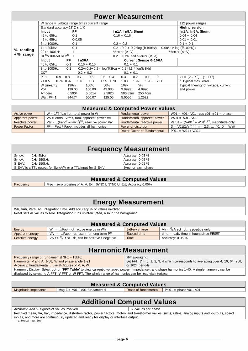
Power Measurement
% reading +% range
W range = voltage range times current range 112 power ranges Standard accuracy 23oC ± 1oC Input PF In1A, In5A, Shunt 45 to 65Hz 0-1 0.16 + 0.16 45 to 65Hz 0-0.05 3 to 1000Hz 0-1 0.2 + 0.2
High precision In1A, In5A, Shunt 0.04 + 0.04 0.01 + 0.01 0.1 + 0.1
1 to 20kHz 0-1 0.2+(0.2 + 0.2*log (f/100Hz) + 0.08*k1*log (f/100Hz)) 20 to 100kHz 1 %error (A+V) %error (A+V) DC1)//100-500kHz1) 1 0.2 + 0.2// add %error (V+A) Input PF In30A Current Sensor 0-100A 45 to 65Hz 0-1 0.16 + 0.16 0.1 + 0.1
3 to 1000Hz 0-1 0.2+(0.2+0.2 * log(f/3Hz) + 0.1 *k1 * log(f/3Hz) DC1) 0.2 + 0.2 0.1 + 0.1 PF 1 0.9 0.8 0.7 0.6 0.5 0.4 0.3 0.2 0.1 0 k1 0.5 0.74 0.97 1.18 1.38 1.55 1.70 1.83 1.92 1.98 2.00
k1 = (2 –PF4) / (1+PF2) 1) Typical max. error
W Linearity 130% 100% 50% 10% 5% Volt 130.00 100.00 49.985 9.9992 4.9990 Ampere 6.5004 5.0014 2.5020 500.82m 250.40m Watt PF=1 844.74 500.07 125.05 5.0056 1.2522
Typical linearity of voltage, current and power
Measured & Computed Power Values
Active power W = 1/T T0 ui dt, total power in W Fundamental power W01 = A01 V01 cos 01, 01 = phase Apparent power VA = Arms Vrms, total apparent power VA Fundamental apparent power VA01 = A01 V01 Reactive power Var = (Papp2 – Pact2)1/2, reactive power Var Fundamental reactive power Var01 = (VA012 – W012)1/2, magnitude only Power Factor PF = Pact / Papp, includes all harmonics Power of distortion D = V01(An2)1/2, n = 2,3, …, 40; D in Watt Power Factor of Fundamental PF01 = W01 / VA01
Frequency Measurement SyncA: 2Hz-5kHz SyncV: 2Hz-150kHz S_ExtV: 2Hz-150kHz S_ExtV is a TTL output for SyncA/V or a TTL input for S_ExtV
Accuracy: 0.05 % Accuracy: 0.05 % Accuracy: 0.05 % Sync for each phase
Measured & Computed Values
Frequency Freq =zero crossing of A, V, Ext; SYNC I, SYNC U, Ext; Accuracy 0.05%
Energy Measurement Wh, VAh, Varh, Ah, integration time. Add accuracy % of values involved. Reset sets all values to zero. Integration runs uninterrupted, also in the background.
Measured & Computed Values
Energy Wh = t0 Pact dt, active energy in Wh Battery charge Ah = t0 Arect dt, is positive only Apparent energy VAh = t0 Papp dt, use it for long term PF Elapsed time time = t0 dt, time in hours since RESET Reactive energy VAR = t0 Prea dt, can be positive / negative Time Accuracy: 0.05 %
Harmonic Measurement
Frequency range of fundamental 3Hz – 15kHz Harmonics: V and A: 1-88; W and phase angle 1-21 Accuracy: Fundamental1), use % figures of V, A, W
FFT averaging: Set FFT ID = 0, 1, 2, 3, 4 which corresponds to averaging over 4, 16, 64, 256, or 1024 periods.
Harmonic Display: Select button ‘FFT Table’ to view current-, voltage-, power-, impedance-, and phase harmonics 1-40. A single harmonic can be displayed by selecting A FFT, V FFT or W FFT. The whole range of harmonics can be read via interface.
Measured & Computed Values
Magnitude impedance Mag Z = V01 / A01 fundamental Phase of fundamental Phi01 = phase V01, A01
Additional Computed Values Accuracy: Add % figures of values involved 65 values per phase Rectified mean, VA, Var, impedance, distortion factor, power factors, motor- and transformer values, sums, ratios, analog inputs and -outputs, speed inputs, and more are continuously updated and ready for display or interface output.
1) Typical max. Error
page 7
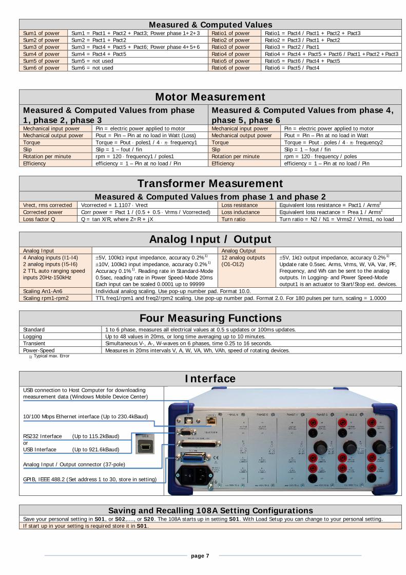
Measured & Computed Values Sum1 of power Sum1 = Pact1 + Pact2 + Pact3; Power phase 1+2+3 Ratio1 of power Ratio1 = Pact4 / Pact1 + Pact2 + Pact3 Sum2 of power Sum2 = Pact1 + Pact2 Ratio2 of power Ratio2 = Pact3 / Pact1 + Pact2 Sum3 of power Sum3 = Pact4 + Pact5 + Pact6; Power phase 4+5+6 Ratio3 of power Ratio3 = Pact2 / Pact1 Sum4 of power Sum4 = Pact4 + Pact5 Ratio4 of power Ratio4 = Pact4 + Pact5 + Pact6 / Pact1 +Pact2 +Pact3 Sum5 of power Sum5 = not used Ratio5 of power Ratio5 = Pact6 / Pact4 + Pact5 Sum6 of power Sum6 = not used Ratio6 of power Ratio6 = Pact5 / Pact4
Motor Measurement Measured & Computed Values from phase 1, phase 2, phase 3
Measured & Computed Values from phase 4, phase 5, phase 6
Mechanical input power Pin = electric power applied to motor Mechanical input power Pin = electric power applied to motor Mechanical output power Pout = Pin – Pin at no load in Watt (Loss) Mechanical output power Pout = Pin – Pin at no load in Watt Torque Torque = Pout poles1 / 4 frequency1 Torque Torque = Pout poles / 4 frequency2 Slip Slip = 1 – fout / fin Slip Slip = 1 – fout / fin Rotation per minute rpm = 120 frequency1 / poles1 Rotation per minute rpm = 120 frequency / poles Efficiency efficiency = 1 – Pin at no load / Pin Efficiency efficiency = 1 – Pin at no load / Pin
Transformer Measurement
Measured & Computed Values from phase 1 and phase 2 Vrect, rms corrected Vcorrected = 1.1107 Vrect Loss resistance Equivalent loss resistance = Pact1 / Arms2 Corrected power Corr power = Pact 1 / (0.5 + 0.5 Vrms / Vcorrected) Loss inductance Equivalent loss reactance = Prea 1 / Arms2 Loss factor Q Q = tan X/R, where Z=R + jX Turn ratio Turn ratio = N2 / N1 = Vrms2 / Vrms1, no load
Analog Input / Output
Analog Input Analog Output 4 Analog inputs (I1-I4) 2 analog inputs (I5-I6) 2 TTL auto ranging speed inputs 20Hz-150kHz
5V, 100k input impedance, accuracy 0.2%1) 10V, 100k input impedance, accuracy 0.2%1) Accuracy 0.1%1). Reading rate in Standard-Mode 0.5sec, reading rate in Power Speed-Mode 20ms Each input can be scaled 0.0001 up to 99999
12 analog outputs (O1-O12)
5V, 1k output impedance, accuracy 0.2%1) Update rate 0.5sec. Arms, Vrms, W, VA, Var, PF, Frequency, and Wh can be sent to the analog outputs. In Logging- and Power Speed-Mode output1 is an actuator to Start/Stop ext. devices.
Scaling An1-An6 Individual analog scaling. Use pop-up number pad. Format 10.0. Scaling rpm1-rpm2 TTL freq1/rpm1 and freq2/rpm2 scaling. Use pop-up number pad. Format 2.0. For 180 pulses per turn, scaling = 1.0000
Four Measuring Functions
Standard 1 to 6 phase, measures all electrical values at 0.5 s updates or 100ms updates. Logging Up to 48 values in 20ms, or long time averaging up to 10 minutes. Transient Simultaneous V-, A-, W-waves on 6 phases, time 0.25 to 16 seconds. Power-Speed Measures in 20ms intervals V, A, W, VA, Wh, VAh, speed of rotating devices.
1) Typical max. Error
Interface
USB connection to Host Computer for downloading measurement data (Windows Mobile Device Center) 10/100 Mbps Ethernet interface (Up to 230.4kBaud) RS232 Interface (Up to 115.2kBaud) or USB Interface (Up to 921.6kBaud) Analog Input / Output connector (37-pole) GPIB, IEEE 488.2 (Set address 1 to 30, store in setting)
Saving and Recalling 108A Setting Configurations Save your personal setting in S01, or S02,...., or S20. The 108A starts up in setting S01. With Load Setup you can change to your personal setting. If start up in your setting is required store it in S01.
page 8
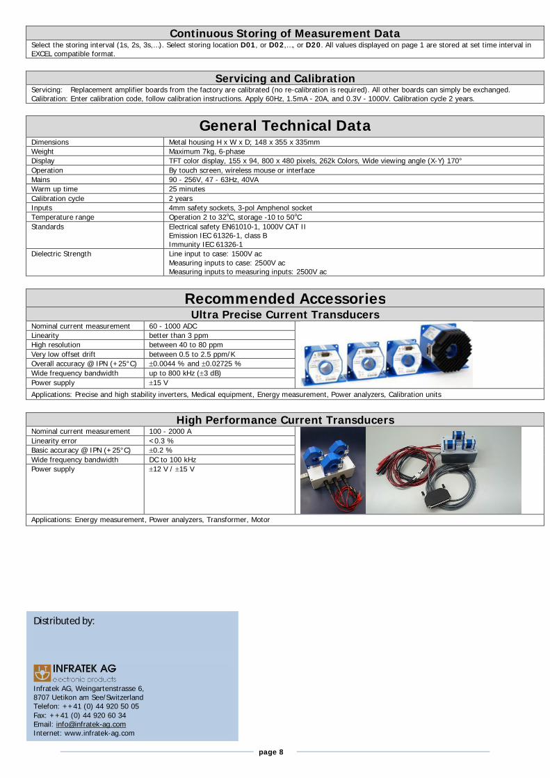
Continuous Storing of Measurement Data Select the storing interval (1s, 2s, 3s,…). Select storing location D01, or D02,…, or D20. All values displayed on page 1 are stored at set time interval in EXCEL compatible format.
Servicing and Calibration
Servicing: Replacement amplifier boards from the factory are calibrated (no re-calibration is required). All other boards can simply be exchanged. Calibration: Enter calibration code, follow calibration instructions. Apply 60Hz, 1.5mA - 20A, and 0.3V - 1000V. Calibration cycle 2 years.
General Technical Data
Dimensions Metal housing H x W x D; 148 x 355 x 335mm Weight Maximum 7kg, 6-phase Display TFT color display, 155 x 94, 800 x 480 pixels, 262k Colors, Wide viewing angle (X-Y) 170° Operation By touch screen, wireless mouse or interface Mains 90 - 256V, 47 - 63Hz, 40VA Warm up time 25 minutes Calibration cycle 2 years Inputs 4mm safety sockets, 3-pol Amphenol socket Temperature range Operation 2 to 32oC, storage -10 to 50oC Standards Electrical safety EN61010-1, 1000V CAT II
Emission IEC 61326-1, class B Immunity IEC 61326-1
Dielectric Strength Line input to case: 1500V ac Measuring inputs to case: 2500V ac Measuring inputs to measuring inputs: 2500V ac
Recommended Accessories Ultra Precise Current Transducers
Nominal current measurement 60 - 1000 ADC
Linearity better than 3 ppm High resolution between 40 to 80 ppm Very low offset drift between 0.5 to 2.5 ppm/K Overall accuracy @ IPN (+25°C) 0.0044 % and 0.02725 % Wide frequency bandwidth up to 800 kHz (3 dB) Power supply 15 V Applications: Precise and high stability inverters, Medical equipment, Energy measurement, Power analyzers, Calibration units
High Performance Current Transducers
Nominal current measurement 100 - 2000 A
Linearity error <0.3 % Basic accuracy @ IPN (+25°C) 0.2 % Wide frequency bandwidth DC to 100 kHz Power supply 12 V / 15 V
Applications: Energy measurement, Power analyzers, Transformer, Motor
Distributed by:
Infratek AG, Weingartenstrasse 6, 8707 Uetikon am See/Switzerland Telefon: ++41 (0) 44 920 50 05 Fax: ++41 (0) 44 920 60 34 Email: [email protected] Internet: www.infratek-ag.com

![IBM Cognos Dynamic Query Analyzer 1021 Gn Upublic.dhe.ibm.com/software/data/cognos/... · ]to IBM Cognos Dynamic Query Analyzer sWS MμCªi≤UzW M {íípªñAH ∩ ÷V DC p ÷ΩTA](https://static.fdocument.org/doc/165x107/5fa869d672140d6d3b0d5244/ibm-cognos-dynamic-query-analyzer-1021-gn-to-ibm-cognos-dynamic-query-analyzer.jpg)


![IBM Cognos Dynamic Query Analyzer 1020 Gn Upublic.dhe.ibm.com/software/data/cognos/documentation/docs/zh-t… · ]to IBM Cognos Dynamic Query Analyzer sWS MμCªi≤UzW M {íípªñAH](https://static.fdocument.org/doc/165x107/5fa869d672140d6d3b0d5247/ibm-cognos-dynamic-query-analyzer-1020-gn-to-ibm-cognos-dynamic-query-analyzer.jpg)