Harmonic Minimization using PSO of meld μgird-MLCI
7
M.Manigandan et al. Int. Journal of Engineering Research and Applications www.ijera.com ISSN : 2248-9622, Vol. 5, Issue 5, ( Part -1) May 2015, pp.75-81 www.ijera.com 75 | Page Harmonic Minimization using PSO of meld μgird-MLCI M.Manigandan *1 , Dr.B.Basavaraja 2 and G.Srikanth 3 Assistant Professor *1 , Professor & Chairman 2 , M.Tech Student 3 Dept. of E.E.E. GITAM University 1, 3 , University BDT College of Engineering 2 Abstract Microgrids are new approach of electrical systems consisting of distributed generators, renewable energy sources and sensitive loads. The objective of microgrid operation is to serve reliable and high-quality electric power regardless of faults or abnormal operating conditions. A transformation is being observed to advance the part of distributed generations from alternate the constitutional source in the network of microgrid. In this paper Microgrid with three important distributed generators & an effective solution for protection of sensitive loads against voltage disturbances in power distribution system are considered. The main objective is to lower the total harmonic distortion (THD) of the cascaded multilevel inverter, which is an optimization problem and can be clear up by applying particle swarm optimization (PSO) approach are considered in the paper. The simulation outcome fair that the prospective PSO method is truly adept of concluding outstanding attributes of the decision to eliminate the 3rd, 5th and 7th order harmonics and within the range of modulation index the total harmonic distortion must be reduced for meld μgrid-MLCI. Keywords- Microgrid (μ-grid), Optimized harmonic stepped waveform (OHSW), particle swarm optimization (PSO), Total harmonic distortion (THD) I. INTRODUCTION The electrical grid is tending to be more distributed, intelligent, and flexible. The trend of this new grid is to become more and more distributed, and hence the energy generation and consumption areas cannot be conceived separately. Nowadays, electrical and energy engineering has to face a new scenario in which small distributed power generators and dispersed energy storage devices have to be integrated together into the grid. The use of distributed generation (DG) of energy systems makes no sense without using distributed storage systems to cope with the energy balances. Microgrids (MG), also named minigrids, are becoming an important concept to integrate DG and energy storage systems [1-3]. The concept has been developed to cope with the penetration of renewable energy systems, which can be realistic if the final user is able to generate, storage, control, and manage part of the energy that will consume. A trend for the change in the performance of existing distributed generations from backup to immediate energy supply and to have a malleable contact approach which sets up for the concept of Microgrid have become incipient. Managerial and technology, variation for power generation, environmental and economical enticements and the expansion of smaller generating systems like solar, wind, microturbine power generators have opened new goal for on-site power generation by electricity consumers [4]. Most of the home use appliances use DC power either from a battery or after rectification of the AC source. Cascaded Multilevel inverters have drawn terrific importance in huge power operations. It organizes a crave output voltage from DC voltages as inputs. The desired output of a Cascaded Multilevel inverters is incorporating by several individual sources of DC voltages, with a hike of individual sources of DC voltages, the converter voltage output waveform approaches a nearly sinusoidal waveform while using a fundamental frequency switching scheme. There are three major multilevel topologies: cascaded H-bridge, diode clamped, and capacitor clamped. Previously for harmonic elimination several methods have been presented in those mainly optimized harmonic stepped waveform (OHSW) is being used [5]. It is difficult to solve the OHSW equations as these are highly nonlinear in nature and may produce simple, multiple, or even no solutions for a particular value of modulation index. To solve the OHSW equations, they are changed into linear equations which are producing only one solution set, and even for this a proper initial opinion and starting value of modulation index for which the solutions exist, are required. Particle Swarm Optimization (PSO) for solving these equations and attain the harmonic distortion lesser compare to Newton Raphson (NR) methods which are used in OHSW method is implemented. This paper presents the analysis of 7-level cascaded inverter with three H- bridges, solution of three transcendental equations using PSO and elimination of 3 rd , 5 th and 7th order with minimum harmonic distortion and obtain desired fundamental voltage. In this paper Solar, RESEARCH ARTICLE OPEN ACCESS
-
Upload
ijera-editor -
Category
Documents
-
view
219 -
download
0
description
Microgrids are new approach of electrical systems consisting of distributed generators, renewable energy sources and sensitive loads. The objective of microgrid operation is to serve reliable and high-quality electric power regardless of faults or abnormal operating conditions. A transformation is being observed to advance the part of distributed generations from alternate the constitutional source in the network of microgrid. In this paper Microgrid with three important distributed generators & an effective solution for protection of sensitive loads against voltage disturbances in power distribution system are considered. The main objective is to lower the total harmonic distortion (THD) of the cascaded multilevel inverter, which is an optimization problem and can be clear up by applying particle swarm optimization (PSO) approach are considered in the paper. The simulation outcome fair that the prospective PSO method is truly adept of concluding outstanding attributes of the decision
Transcript of Harmonic Minimization using PSO of meld μgird-MLCI
M.Manigandan et al. Int. Journal of Engineering Research and Applications www.ijera.com
ISSN : 2248-9622, Vol. 5, Issue 5, ( Part -1) May 2015, pp.75-81
www.ijera.com 75 | P a g e
Harmonic Minimization using PSO of meld µgird-MLCI
M.Manigandan*1
, Dr.B.Basavaraja
2 and G.Srikanth
3
Assistant Professor*1
, Professor & Chairman2, M.Tech Student
3 Dept. of E.E.E.
GITAM University1, 3
, University BDT College of Engineering2
Abstract Microgrids are new approach of electrical systems consisting of distributed generators, renewable energy
sources and sensitive loads. The objective of microgrid operation is to serve reliable and high-quality electric
power regardless of faults or abnormal operating conditions. A transformation is being observed to advance the
part of distributed generations from alternate the constitutional source in the network of microgrid. In this paper
Microgrid with three important distributed generators & an effective solution for protection of sensitive loads
against voltage disturbances in power distribution system are considered. The main objective is to lower the
total harmonic distortion (THD) of the cascaded multilevel inverter, which is an optimization problem and can
be clear up by applying particle swarm optimization (PSO) approach are considered in the paper. The simulation
outcome fair that the prospective PSO method is truly adept of concluding outstanding attributes of the decision
to eliminate the 3rd, 5th and 7th order harmonics and within the range of modulation index the total harmonic
distortion must be reduced for meld µgrid-MLCI.
Keywords- Microgrid (µ-grid), Optimized harmonic stepped waveform (OHSW), particle swarm optimization
(PSO), Total harmonic distortion (THD)
I. INTRODUCTION The electrical grid is tending to be more
distributed, intelligent, and flexible. The trend of this
new grid is to become more and more distributed,
and hence the energy generation and consumption
areas cannot be conceived separately. Nowadays,
electrical and energy engineering has to face a new
scenario in which small distributed power generators
and dispersed energy storage devices have to be
integrated together into the grid. The use of
distributed generation (DG) of energy systems makes
no sense without using distributed storage systems to
cope with the energy balances. Microgrids (MG),
also named minigrids, are becoming an important
concept to integrate DG and energy storage systems
[1-3]. The concept has been developed to cope with
the penetration of renewable energy systems, which
can be realistic if the final user is able to generate,
storage, control, and manage part of the energy that
will consume. A trend for the change in the
performance of existing distributed generations from
backup to immediate energy supply and to have a
malleable contact approach which sets up for the
concept of Microgrid have become incipient.
Managerial and technology, variation for power
generation, environmental and economical
enticements and the expansion of smaller generating
systems like solar, wind, microturbine power
generators have opened new goal for on-site power
generation by electricity consumers [4]. Most of the
home use appliances use DC power either from a
battery or after rectification of the AC source.
Cascaded Multilevel inverters have drawn
terrific importance in huge power operations. It
organizes a crave output voltage from DC voltages as
inputs. The desired output of a Cascaded Multilevel
inverters is incorporating by several individual
sources of DC voltages, with a hike of individual
sources of DC voltages, the converter voltage output
waveform approaches a nearly sinusoidal waveform
while using a fundamental frequency switching
scheme. There are three major multilevel topologies:
cascaded H-bridge, diode clamped, and capacitor
clamped.
Previously for harmonic elimination several
methods have been presented in those mainly
optimized harmonic stepped waveform (OHSW) is
being used [5]. It is difficult to solve the OHSW
equations as these are highly nonlinear in nature and
may produce simple, multiple, or even no solutions
for a particular value of modulation index. To solve
the OHSW equations, they are changed into linear
equations which are producing only one solution set,
and even for this a proper initial opinion and starting
value of modulation index for which the solutions
exist, are required. Particle Swarm Optimization
(PSO) for solving these equations and attain the
harmonic distortion lesser compare to Newton
Raphson (NR) methods which are used in OHSW
method is implemented. This paper presents the
analysis of 7-level cascaded inverter with three H-
bridges, solution of three transcendental equations
using PSO and elimination of 3rd
, 5th and 7th order
with minimum harmonic distortion and obtain
desired fundamental voltage. In this paper Solar,
RESEARCH ARTICLE OPEN ACCESS
M.Manigandan et al. Int. Journal of Engineering Research and Applications www.ijera.com
ISSN : 2248-9622, Vol. 5, Issue 5, ( Part -1) May 2015, pp.75-81
www.ijera.com 76 | P a g e
Wind and Fuel cell are used as DC sources for
Cascaded Multilevel Inverter
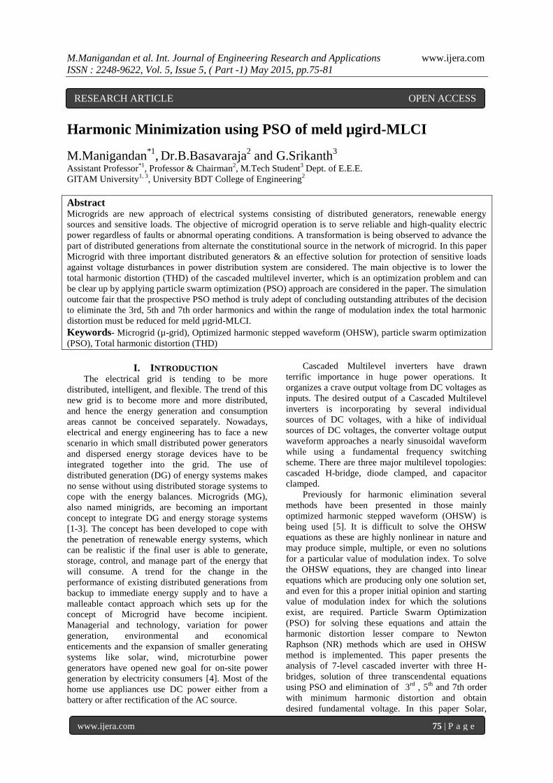
II. PROPOSED CASCADED MULTILEVEL
INVERTER The development of semiconductor technology
has been done by many power electronics research
communities to reach the higher nominal voltages
and currents. In conventional multilevel inverters, the
power semiconductor, switches are combined to
produce a high frequency waveform in positive and
negative polarities. However, there is no need to
utilize all the switches for generating bipolar levels.
This idea has been put into practice by the new
topology. The Cascade multilevel inverter subsists of
a series of the H-bridge inverter units. The cascade
multilevel inverter is to incorporate a desired voltage
from several separate DC sources as shown in
Fig.1.[6] The number of output phase voltage levels
is 2S+1, where S is the number of DC sources and „s‟
is the number of H-bridges connected in cascade per
phase. Among „s‟ number of switching angles,
generally one switching angle is used for
fundamental voltage selection and the remaining (s-
1) switching angles are used to eliminate certain
predominating lower order harmonics. In a three-
phase system with isolated neutral, triplen harmonics
are cancelled out automatically, and only non-triplen
odd harmonics are present. The fundamental voltage
is obtained from the calculated switching angles α1,
α2, α3… αn and „n‟ represents the order of the
harmonics and the switching angles are identical to
the number of DC-sources. The sum of all of the
individual inverter outputs (V1+V2+V3=Vout) as
shown in Figure.2 which are the AC output of each
H-bridge inverter is connected in series such that the
incorporated voltage waveform and accomplished by
connecting the DC source to the AC output side by
using different combinations of the switches .
Fig.1: Schematic diagram of H-bridge series-
connected multilevel inverter.
Fig.2: Switching angles of H-bridge MLCI.
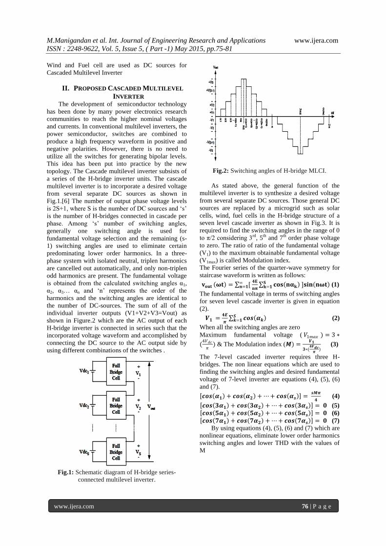
As stated above, the general function of the
multilevel inverter is to synthesize a desired voltage
from several separate DC sources. Those general DC
sources are replaced by a microgrid such as solar
cells, wind, fuel cells in the H-bridge structure of a
seven level cascade inverter as shown in Fig.3. It is
required to find the switching angles in the range of 0
to π/2 considering 3rd
, 5th
and 7th
order phase voltage
to zero. The ratio of ratio of the fundamental voltage
(V1) to the maximum obtainable fundamental voltage
(V1max) is called Modulation index.
The Fourier series of the quarter-wave symmetry for
staircase waveform is written as follows:
𝐯𝐨𝐮𝐭 𝛚𝐭 = [ 𝟒𝐄
𝐧𝛑 𝐜𝐨𝐬 𝐧𝛂𝐤
𝐒𝐤=𝟏
∞𝐧=𝟏 ]𝐬𝐢𝐧 𝐧𝛚𝐭 (1)
The fundamental voltage in terms of switching angles
for seven level cascade inverter is given in equation
(2).
𝑽𝟏 =𝟒𝑬
𝝅 𝒄𝒐𝒔 𝜶𝒌 𝑺
𝒌=𝟏 (2)
When all the switching angles are zero
Maximum fundamental voltage ( 𝑉1𝑚𝑎𝑥 ) = 3 ∗
(4𝑉𝑑𝑐
𝜋) & The Modulation index (𝑴) =
𝑽𝟏
𝟑∗(𝟒𝑽𝒅𝒄
𝝅) (3)
The 7-level cascaded inverter requires three H-
bridges. The non linear equations which are used to
finding the switching angles and desired fundamental
voltage of 7-level inverter are equations (4), (5), (6)
and (7).
𝒄𝒐𝒔 𝜶𝟏 + 𝒄𝒐𝒔 𝜶𝟐 + ⋯ + 𝒄𝒐𝒔 𝜶𝒔 = 𝒔𝑴𝝅
𝟒 (4)
𝒄𝒐𝒔 𝟑𝜶𝟏 + 𝒄𝒐𝒔 𝟑𝜶𝟐 + ⋯ + 𝒄𝒐𝒔 𝟑𝜶𝒔 = 𝟎 (5)
𝒄𝒐𝒔 𝟓𝜶𝟏 + 𝒄𝒐𝒔 𝟓𝜶𝟐 + ⋯ + 𝒄𝒐𝒔 𝟓𝜶𝒔 = 𝟎 (6)
𝒄𝒐𝒔 𝟕𝜶𝟏 + 𝒄𝒐𝒔 𝟕𝜶𝟐 + ⋯ + 𝒄𝒐𝒔 𝟕𝜶𝒔 = 𝟎 (7)
By using equations (4), (5), (6) and (7) which are
nonlinear equations, eliminate lower order harmonics
switching angles and lower THD with the values of
M
M.Manigandan et al. Int. Journal of Engineering Research and Applications www.ijera.com
ISSN : 2248-9622, Vol. 5, Issue 5, ( Part -1) May 2015, pp.75-81
www.ijera.com 77 | P a g e
Fig.3: Schematic diagram of an H-bridge series-
connected cascaded multilevel inverter with
Microgrid as DC Sources.
All the above Equations are evaluated by
considering input voltage values of the Solar (Vpv),
Wind (VW) and Fuel Cell (VFC).
III. MICROGRID (µ-GRID) A. Solar PV:
The PV cell is a specially designed PN junction or
Schottky barrier device. The well-known diode
equation describes the operation of the shaded PV
cell. [7]. In order to obtain an adequate output
voltage, which is a constant DC whose magnitude
depends on the composition in which the solar cells/
modules are connected PV cells are connected in
series to form a PV module.
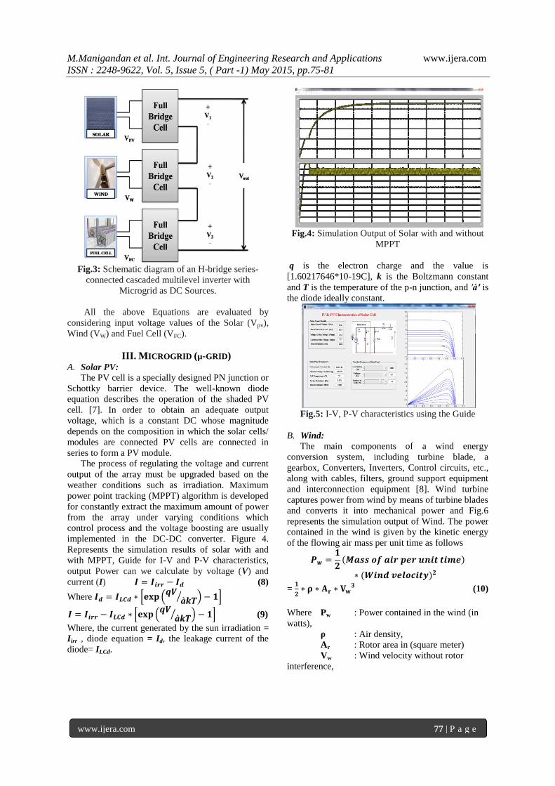
The process of regulating the voltage and current
output of the array must be upgraded based on the
weather conditions such as irradiation. Maximum
power point tracking (MPPT) algorithm is developed
for constantly extract the maximum amount of power
from the array under varying conditions which
control process and the voltage boosting are usually
implemented in the DC-DC converter. Figure 4.
Represents the simulation results of solar with and
with MPPT, Guide for I-V and P-V characteristics,
output Power can we calculate by voltage (V) and
current (I) 𝑰 = 𝑰𝒊𝒓𝒓 − 𝑰𝒅 (8)
Where 𝑰𝒅 = 𝑰𝑳𝑪𝒅 ∗ 𝐞𝐱𝐩 𝒒𝑽
à𝒌𝑻 − 𝟏
𝑰 = 𝑰𝒊𝒓𝒓 − 𝑰𝑳𝑪𝒅 ∗ 𝐞𝐱𝐩 𝒒𝑽
à𝒌𝑻 − 𝟏 (9)
Where, the current generated by the sun irradiation =
Iirr , diode equation = Id, the leakage current of the
diode= ILCd.
Fig.4: Simulation Output of Solar with and without
MPPT
q is the electron charge and the value is
[1.60217646*10-19C], k is the Boltzmann constant
and T is the temperature of the p-n junction, and ′à′ is
the diode ideally constant.
Fig.5: I-V, P-V characteristics using the Guide
B. Wind:
The main components of a wind energy
conversion system, including turbine blade, a
gearbox, Converters, Inverters, Control circuits, etc.,
along with cables, filters, ground support equipment
and interconnection equipment [8]. Wind turbine
captures power from wind by means of turbine blades
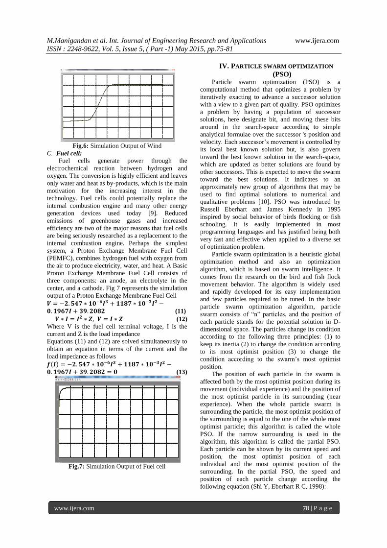
and converts it into mechanical power and Fig.6
represents the simulation output of Wind. The power
contained in the wind is given by the kinetic energy
of the flowing air mass per unit time as follows
𝑷𝒘 =𝟏
𝟐 𝑴𝒂𝒔𝒔 𝒐𝒇 𝒂𝒊𝒓 𝒑𝒆𝒓 𝒖𝒏𝒊𝒕 𝒕𝒊𝒎𝒆
∗ (𝑾𝒊𝒏𝒅 𝒗𝒆𝒍𝒐𝒄𝒊𝒕𝒚)𝟐
= 𝟏
𝟐∗ 𝛒 ∗ 𝐀𝐫 ∗ 𝐕𝐰
𝟑 (10)
Where Pw : Power contained in the wind (in
watts),
ρ : Air density,
Ar : Rotor area in (square meter)
Vw : Wind velocity without rotor
interference,
M.Manigandan et al. Int. Journal of Engineering Research and Applications www.ijera.com
ISSN : 2248-9622, Vol. 5, Issue 5, ( Part -1) May 2015, pp.75-81
www.ijera.com 78 | P a g e
Fig.6: Simulation Output of Wind
C. Fuel cell:
Fuel cells generate power through the
electrochemical reaction between hydrogen and
oxygen. The conversion is highly efficient and leaves
only water and heat as by-products, which is the main
motivation for the increasing interest in the
technology. Fuel cells could potentially replace the
internal combustion engine and many other energy
generation devices used today [9]. Reduced
emissions of greenhouse gases and increased
efficiency are two of the major reasons that fuel cells
are being seriously researched as a replacement to the
internal combustion engine. Perhaps the simplest
system, a Proton Exchange Membrane Fuel Cell
(PEMFC), combines hydrogen fuel with oxygen from
the air to produce electricity, water, and heat. A Basic
Proton Exchange Membrane Fuel Cell consists of
three components: an anode, an electrolyte in the
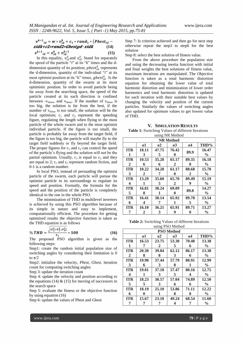
center, and a cathode. Fig 7 represents the simulation
output of a Proton Exchange Membrane Fuel Cell
𝑽 = −𝟐. 𝟓𝟒𝟕 ∗ 𝟏𝟎−𝟔𝑰𝟑 + 𝟏𝟏𝟖𝟕 ∗ 𝟏𝟎−𝟑𝑰𝟐 −𝟎. 𝟏𝟗𝟔𝟕𝑰 + 𝟑𝟗. 𝟐𝟎𝟖𝟐 (11)
𝑽 ∗ 𝑰 = 𝑰𝟐 ∗ 𝒁, 𝑽 = 𝑰 ∗ 𝒁 (12)
Where V is the fuel cell terminal voltage, I is the
current and Z is the load impedance
Equations (11) and (12) are solved simultaneously to
obtain an equation in terms of the current and the
load impedance as follows
𝒇 𝑰 = −𝟐. 𝟓𝟒𝟕 ∗ 𝟏𝟎−𝟔𝑰𝟑 + 𝟏𝟏𝟖𝟕 ∗ 𝟏𝟎−𝟑𝑰𝟐 −𝟎. 𝟏𝟗𝟔𝟕𝑰 + 𝟑𝟗. 𝟐𝟎𝟖𝟐 = 𝟎 (13)
Fig.7: Simulation Output of Fuel cell
IV. PARTICLE SWARM OPTIMIZATION
(PSO) Particle swarm optimization (PSO) is a
computational method that optimizes a problem by
iteratively exacting to advance a successor solution
with a view to a given part of quality. PSO optimizes
a problem by having a population of successor
solutions, here designate bit, and moving these bits
around in the search-space according to simple
analytical formulae over the successor 's position and
velocity. Each successor‟s movement is controlled by
its local best known solution but, is also govern
toward the best known solution in the search-space,
which are updated as better solutions are found by
other successors. This is expected to move the swarm
toward the best solutions. It indicates to an
approximately new group of algorithms that may be
used to find optimal solutions to numerical and
qualitative problems [10]. PSO was introduced by
Russell Eberhart and James Kennedy in 1995
inspired by social behavior of birds flocking or fish
schooling. It is easily implemented in most
programming languages and has justified being both
very fast and effective when applied to a diverse set
of optimization problem.
Particle swarm optimization is a heuristic global
optimization method and also an optimization
algorithm, which is based on swarm intelligence. It
comes from the research on the bird and fish flock
movement behavior. The algorithm is widely used
and rapidly developed for its easy implementation
and few particles required to be tuned. In the basic
particle swarm optimization algorithm, particle
swarm consists of “n” particles, and the position of
each particle stands for the potential solution in D-
dimensional space. The particles change its condition
according to the following three principles: (1) to
keep its inertia (2) to change the condition according
to its most optimist position (3) to change the
condition according to the swarm‟s most optimist
position.
The position of each particle in the swarm is
affected both by the most optimist position during its
movement (individual experience) and the position of
the most optimist particle in its surrounding (near
experience). When the whole particle swarm is
surrounding the particle, the most optimist position of
the surrounding is equal to the one of the whole most
optimist particle; this algorithm is called the whole
PSO. If the narrow surrounding is used in the
algorithm, this algorithm is called the partial PSO.
Each particle can be shown by its current speed and
position, the most optimist position of each
individual and the most optimist position of the
surrounding. In the partial PSO, the speed and
position of each particle change according the
following equation (Shi Y, Eberhart R C, 1998):
M.Manigandan et al. Int. Journal of Engineering Research and Applications www.ijera.com
ISSN : 2248-9622, Vol. 5, Issue 5, ( Part -1) May 2015, pp.75-81
www.ijera.com 79 | P a g e
𝒗𝒌+𝟏𝒊𝒅 = 𝒘 ∗ 𝒗𝒊𝒅
𝒌 + 𝒄𝟏 ∗ 𝒓𝒂𝒏𝒅𝟏 ∗ 𝑷𝒃𝒆𝒔𝒕𝒊𝒅 −
𝒙𝒊𝒅𝒌+𝒄𝟐∗𝒓𝒂𝒏𝒅𝟐∗𝑮𝒃𝒆𝒔𝒕𝒈𝒅−𝒙𝒊𝒅𝒌 (14)
𝒙𝒌+𝟏𝒊𝒅 = 𝒙𝒊𝒅
𝒌 + 𝒗𝒊𝒅𝒌+𝟏 (15)
In this equality, 𝑣𝑖𝑑𝑘 and 𝑥𝑖𝑑
𝑘 Stand for separately
the speed of the particle “i” at its “k” times and the d-
dimension quantity of its position; 𝑝𝑏𝑒𝑠𝑡𝑖𝑑𝑘 represents
the d-dimension, quantity of the individual “i” at its
most optimist position at its “k” times, 𝑔𝑏𝑒𝑠𝑡𝑖𝑑𝑘 Is the
d-dimension, quantity of the swarm at its most
optimistic position. In order to avoid particle being
far away from the searching space, the speed of the
particle created at its each direction is confined
between -vdmax, and vdmax. If the number of vdmax is
too big, the solution is far from the best, if the
number of vdmax is too small, the solution will be the
local optimism; c1 and c2 represent the speeding
figure, regulating the length when flying to the most
particle of the whole swarm and to the most optimist
individual particle. If the figure is too small, the
particle is probably far away from the target field, if
the figure is too big, the particle will maybe fly to the
target field suddenly or fly beyond the target field.
The proper figures for c1 and c2 can control the speed
of the particle‟s flying and the solution will not be the
partial optimism. Usually, c1 is equal to c2 and they
are equal to 2; r1 and r2 represent random fiction, and
0-1 is a random number.
In local PSO, instead of persuading the optimist
particle of the swarm, each particle will pursue the
optimist particle in its surroundings to regulate its
speed and position. Formally, the formula for the
speed and the position of the particle is completely
identical to the one in the whole PSO.
The minimization of THD in multilevel inverters
is achieved by using this PSO algorithm because of
its simple in nature and easy to implement,
computationally efficient. The procedure for getting
optimized results the objective function is taken as
the THD equation is as follows
% 𝑻𝑯𝑫 = (𝑽𝟐
𝟐+𝑽𝟑𝟐+𝑽𝒏
𝟐)
𝑽𝟏∗ 𝟏𝟎𝟎 (16)
The proposed PSO algorithm is given as the
following steps:
Step1: create the random initial population size of
switching angles by considering their limitation is 0
to π/2
Step2: initialize the velocity, Pbest, Gbest, iteration
count for computing switching angles
Step 3: update the iteration count
Step 4: update the velocity and position according to
the equations (14) & (15) for moving of successors in
the search space
Step 5: evaluate the fitness or the objective function
by using equation (16)
Step 6: update the values of Pbest and Gbest
Step 7: Is criterion achieved and then go for next step
otherwise repeat the step3 to step6 for the best
solution
Step 8: select the best solution of fitness value.
From the above procedure the population size
and using the decreasing inertia function with initial
and final weights the best solutions of fitness value,
maximum iterations are manipulated. The Objective
function is taken as a total harmonic distortion
equation for obtaining the lower value of total
harmonic distortion and minimization of lower order
harmonics and total harmonic distortion is updated
for each iteration with their suitable best values by
changing the velocity and position of the current
particles. Similarly the values of switching angles
also updated for optimum values to get lowest value
of THD.
V. SIMULATION RESULTS Table 1: Switching Values of different Iterations
using NR Method
NR Method
α1 α2 α3 α4 THD%
ITR
1
18.11
3
47.75
5
76.42
0 89.9
16.47
%
ITR
2
10.53
6
35.28
6
65.17
2
89.35
8
16.18
%
ITR
3
10.22
2
34.28
7
61.17
0
88.68
2
15.70
%
ITR
4
13.29
1
35.60
5
65.70
2
89.49
9
15.19
%
ITR
5
16.81
8
38.24
1
69.09
0 89.8
14.27
%
ITR
6
16.41
4
38.14
7
65.92
1
89.78
5
13.54
%
ITR
7
16.10
2
36.21
3
65.91
9
89.71
0
13.27
%
Table 2: Switching Values of different Iterations
using PSO Method
PSO Method
α1 α2 α3 α4 THD%
ITR
1
16.53
7
23.75
2
53.30
5
70.48
6
13.38
%
ITR
2
20.30
8
39.84
8
62.12
3
86.17
6
13.38
%
ITR
3
19.90
6
37.44
3
57.79
8
80.91
1
12.99
%
ITR
4
19.01
1
37.18
3
57.47
5
80.16
4
12.75
%
ITR
5
18.23
5
30.57
3
57.04
6
74.89
6
12.50
%
ITR
6
18.19
0
25.10
1
53.86
8
71.11
8
12.22
%
ITR
7
15.67
7
23.10
7
49.24
4
68.54
7
11.60
%
M.Manigandan et al. Int. Journal of Engineering Research and Applications www.ijera.com
ISSN : 2248-9622, Vol. 5, Issue 5, ( Part -1) May 2015, pp.75-81
www.ijera.com 80 | P a g e
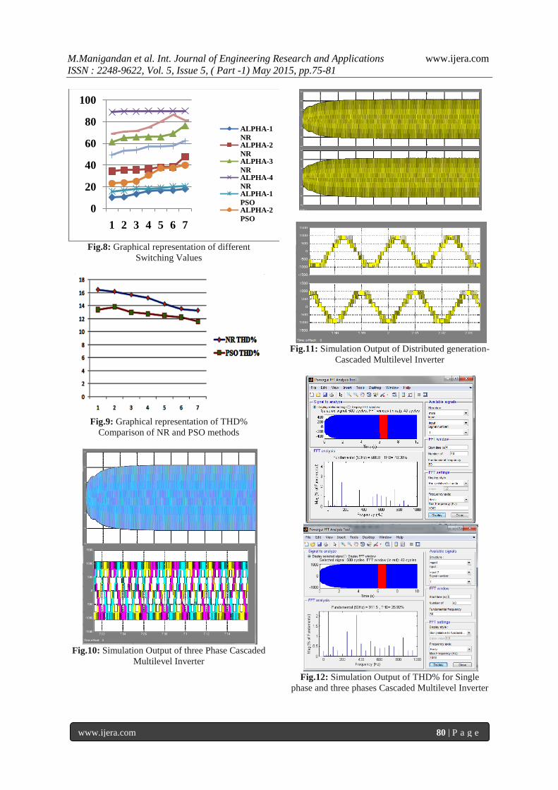
Fig.8: Graphical representation of different
Switching Values
Fig.9: Graphical representation of THD%
Comparison of NR and PSO methods
Fig.10: Simulation Output of three Phase Cascaded
Multilevel Inverter
Fig.11: Simulation Output of Distributed generation-
Cascaded Multilevel Inverter
Fig.12: Simulation Output of THD% for Single
phase and three phases Cascaded Multilevel Inverter
0
20
40
60
80
100
1 2 3 4 5 6 7
ALPHA-1
NRALPHA-2
NRALPHA-3
NRALPHA-4
NRALPHA-1
PSOALPHA-2
PSO

M.Manigandan et al. Int. Journal of Engineering Research and Applications www.ijera.com
ISSN : 2248-9622, Vol. 5, Issue 5, ( Part -1) May 2015, pp.75-81
www.ijera.com 81 | P a g e
VI. CONCLUSION As the renewable energy sources increase in day
to day life, microgrid will have more advantage in
having for the perfect effective DC source for
different resources and connected to the different
application. The Transmission and Distribution
network are already loaded to their full capacity and
more energy can be fed to the customers only with
additional spending on Transmission and Distribution
expansion. The Microgrid is an aggregation of these
resources and connected to the different application
as DC source. The PSO method gives the lower
THD% compared to the other Iterative methods like
NR method. In recent years the approach for the
elimination of harmonics in multilevel inverters by
using PSO method has been done by taking better
switching angles as the objective function. The paper
discusses about the effective elimination of lower
order harmonics and better results in minimization of
THD% are a presented for meld µgird-MLCI for the
benefit of the
REFERENCE [1] R. E. Brow, J. Pan, X. Feng and K. Koutlev,
“Sitting Distributed Generation to defer
T&D Expansion,” Proc. 2001 IEEE PES
Transmission and Distribution Conf. Expo.
vol.2, pp. 622-627.
[2] T.E. McDermott and R.C. Dugan,
“Distributed Generation Impact on
Reliability and Power Quality” in Proc. of
IEEE Conf. on Rural Electric Power,2002,
pp. D3-D3_7.
[3] R. Lasseter, A. Akhil, C. Marnay, J.
Stephens, J. Dagle, R. Guttromson, A. S.
Meliopoulous, R. Yinger, and J. Eto, “White
paper on Integration of Distributed Energy
Resources ,The CERTS MICROGRID
Concept,” Consultant Report California
Energy Commission, U.S. Department of
Energy, Berkeley, CA, LBNL-50829, April
2002.
[4] P. Chiredeja and R. Ramakumar, “An
approach to quantify the technical benefits
of distributed generation,” IEEE Trans.
Energy Conversation, vol.19, no. 4, pp. 746-
773, Dec. 2004.
[5] Zhong Du, Leon M. Tolbert, John N.
Chiasson “Reduced Switching Frequency
Computed PWM method for multilevel
converter control” Power Electronics
Specialists Conference, 2005. PESC ‟05.
IEEE, 2005, Page(s): 2560 – 2564.
[6] John N. Chiasson, Leon M. Tolbert,
“Elimination of Harmonics In Multilevel
Inverters Using the theory of Symmetric
polynomial and Resultant” Proceedings of
the 42nd IEEE Conference on Decision and
Control Maui, Hawaii USA, December
2003.
[7] S.L. Helter et.al, “photovoltaic module and
array evaluation,”IEEE 1984,pp 700-704.
[8] Hoa M Nguyen and D.Subbaram Naidu
“Advanced control strategies for wind
energy systems”IEEE PES power system
conference & Exposition
(PSCE),Phonix,AZ,USA 20-23 march 2011.
[9] EG&G Technical Services Inc., “Fuel cell
handbook (6th
edition),” Tech. Rep., U.S.
Department of Energy - N.E.T.L., 2002.
[10] H.Taghizadeh and M. Tarafdar Hagh,
“Harmonic Elimination of Multilevel
Inverters Using Particle Swarm
Optimization” Industrial electronics, 2008,
ISIE 2008. IEEE International symposium
on Industrial Electronics. 18th November
2008.


![HITCHIN HARMONIC MAPS ARE IMMERSIONShomepages.math.uic.edu › ~andysan › HitImmersion.pdf · HITCHIN HARMONIC MAPS ARE IMMERSIONS ANDREW SANDERS ... [SY78] about harmonic maps](https://static.fdocument.org/doc/165x107/5f13addc3b5c9d385756c3dc/hitchin-harmonic-maps-are-a-andysan-a-hitimmersionpdf-hitchin-harmonic-maps.jpg)