
Gravity Wall Design
28
GRAVITY RETAINING WALL DESIGN Initial Parameters Density of Rubble Wall 24 kN/m3 Density of Soil 18 kN/m3 Density of Concrete 24 kN/m3 H1 4.00 m H2 0.60 m d 0.25 m B1 0.000 m B2 3.58 m B3 0.000 m Surcharge load S 5.00 kN/m2 Bearing capacity 200 kN/m2 Inclined angle of wall β 85 ˚ 1.48 rad Inclined angle of soil on to δ 0 ˚ 0.00 rad Friction angle of soil φ 30 ˚ 0.52 rad 0.33 3.00 Depth of shear key 0.75 m μ 0.27 Gravity Wall Dimensions Calculations 0.3 0.55 0.55 Slice LOAD/kN γr γs γc σall Ka Kp hs a1 h1
description
spread sheet
Transcript of Gravity Wall Design
GRAVITY RETAINING WALL DESIGN
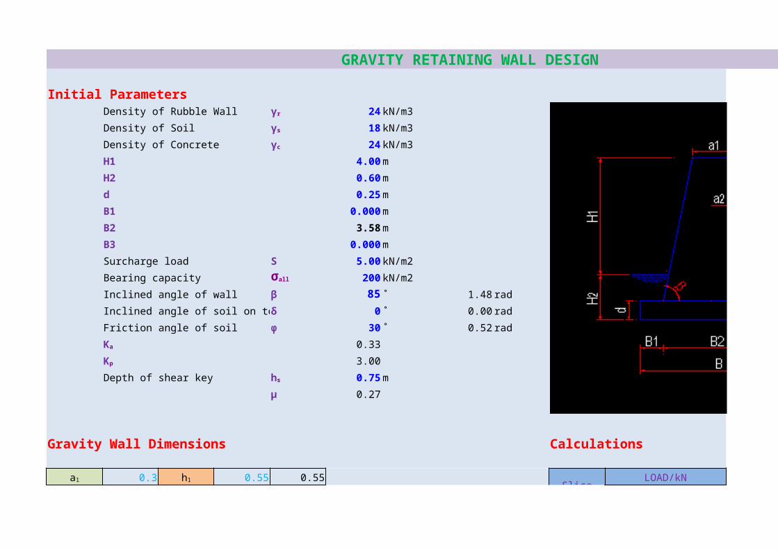
Initial ParametersDensity of Rubble Wall 24 kN/m3
Density of Soil 18 kN/m3
Density of Concrete 24 kN/m3
H1 4.00 m
H2 0.60 m
d 0.25 m
B1 0.000 m
B2 3.58 m
B3 0.000 m
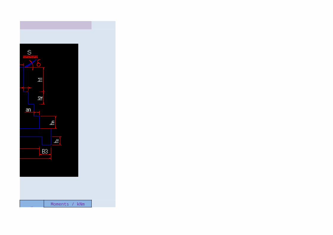
Surcharge load S 5.00 kN/m2
Bearing capacity 200 kN/m2
Inclined angle of wall β 85 ˚ 1.48 rad
Inclined angle of soil on top δ 0 ˚ 0.00 rad
Friction angle of soil φ 30 ˚ 0.52 rad
0.33
3.00
Depth of shear key 0.75 m
μ 0.27
Gravity Wall Dimensions Calculations
0.3 0.55 0.55 Slice LOAD/kN x Moments / kNm
γr
γs
γc
σall
Ka
Kp
hs
a1 h1
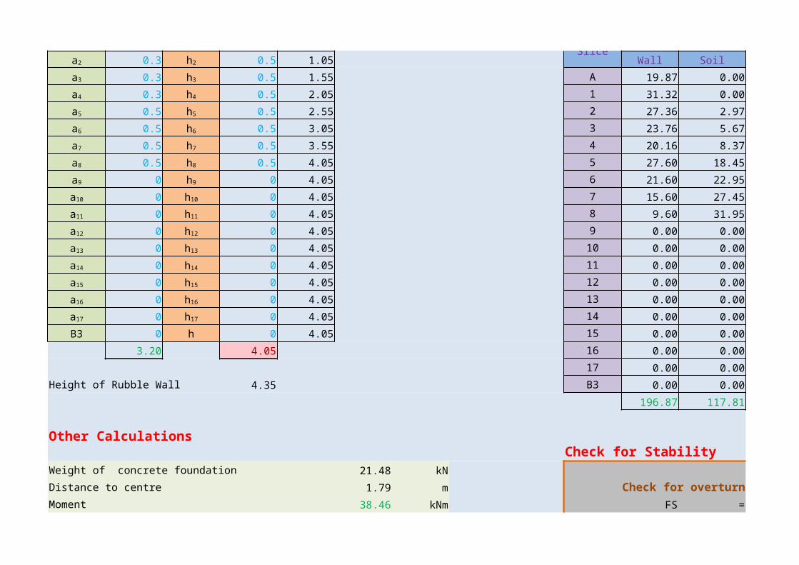
0.3 0.5 1.05Slice
Wall Soilx
Wall
0.3 0.5 1.55 A 19.87 0.00 0.25 5.04
0.3 0.5 2.05 1 31.32 0.00 0.53 16.62
0.5 0.5 2.55 2 27.36 2.97 0.83 22.72
0.5 0.5 3.05 3 23.76 5.67 1.13 26.86
0.5 0.5 3.55 4 20.16 8.37 1.43 28.84
0.5 0.5 4.05 5 27.60 18.45 1.83 50.52
0 0 4.05 6 21.60 22.95 2.33 50.34
0 0 4.05 7 15.60 27.45 2.83 44.16
0 0 4.05 8 9.60 31.95 3.33 31.97
0 0 4.05 9 0.00 0.00 3.58 0.00
0 0 4.05 10 0.00 0.00 3.58 0.00
0 0 4.05 11 0.00 0.00 3.58 0.00
0 0 4.05 12 0.00 0.00 3.58 0.00
0 0 4.05 13 0.00 0.00 3.58 0.00
0 0 4.05 14 0.00 0.00 3.58 0.00
B3 0 h 0 4.05 15 0.00 0.00 3.58 0.00
3.20 4.05 16 0.00 0.00 3.58 0.0017 0.00 0.00 3.58 0.00
Height of Rubble Wall 4.35 B3 0.00 0.00 3.58 0.00
196.87 117.81 277.08
Other CalculationsCheck for Stability
Weight of concrete foundation 21.48 kNDistance to centre 1.79 m Check for overturningMoment 38.46 kNm FS = Sum of stabilizing Moments
a2 h2
a3 h3
a4 h4
a5 h5
a6 h6
a7 h7
a8 h8
a9 h9
a10 h10
a11 h11
a12 h12
a13 h13
a14 h14
a15 h15
a16 h16
a17 h17

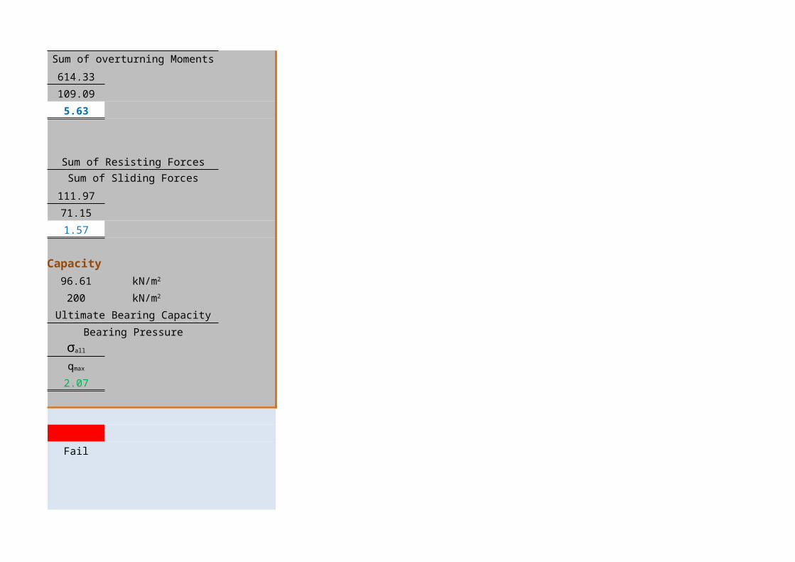
Sum of overturning Moments
Weight of soil on length B1 0.096 kN = 614.33Distance to centre 0.015 m 109.09Moment 0.001 kNm = 5.63
Equivalent height of surcharge load 0.28 m Check for SlidingForce due to surcharge load 7.67 kN FS = Sum of Resisting ForcesHorizental Component 7.67 kN Sum of Sliding Forces
Distance to load centre 1.53 m = 111.97Moment 11.76 kNm 71.15Vertical Component 0.00 kN = 1.57Distance to load centre 0.00 mMoment 0.00 kNm Check for Bearing Capacity
= 96.61Active force on the wall 63.48 kN = 200Horizental Component 63.48 kN FS = Ultimate Bearing CapacityDistance to load centre 1.53 m Bearing PressureMoment 97.34 kNm =Vertical Component 0.00 kNDistance to load centre 0.00 m = 2.07Moment 0.00 kNm
ColorsPassive force on the wall 21.87 kNDistance to load centre 0.30 m Over Satisfy FailMoment 6.56 kNm
Weight of the soil wedge above the top level of the wall = 0.00 kN
he
Ps
Psh
Psv
qmax kN/m2
Pa σall kN/m2
Pah
σall
Pav qmax

Distance to the load centre from toe = 0.00 mMoment = 0.00 kNm
Friction force along bottom of the concrete base,
F = = 336.26 kN
= 90.10 kN
1.81 m
3.58 m
Resultant in middle thirdBearing pressures under the Foundation
= 91.21
= 96.61
μRv , Rv
Distance to the Resultant Force R from toe, LR
Width of the Concrete Foundation, B
q1 kN/m2
q2 kN/m2
GRAVITY RETAINING WALL DESIGN
Moments / kNm

Soil
0.00
0.00
2.47
6.41
11.97
33.77
53.49
77.70
106.41
0.00
0.00
0.00
0.00
0.00
0.00
0.00
0.00
0.00
0.00
292.22
Sum of stabilizing Moments
Sum of overturning Moments
Sum of Resisting ForcesSum of Sliding Forces
Ultimate Bearing Capacity
Bearing Pressure
GRAVITY RETAINING WALL DESIGN
Initial ParametersDensity of Rubble Wall 24 kN/m3
Density of Soil 18 kN/m3
Density of Concrete 24 kN/m3
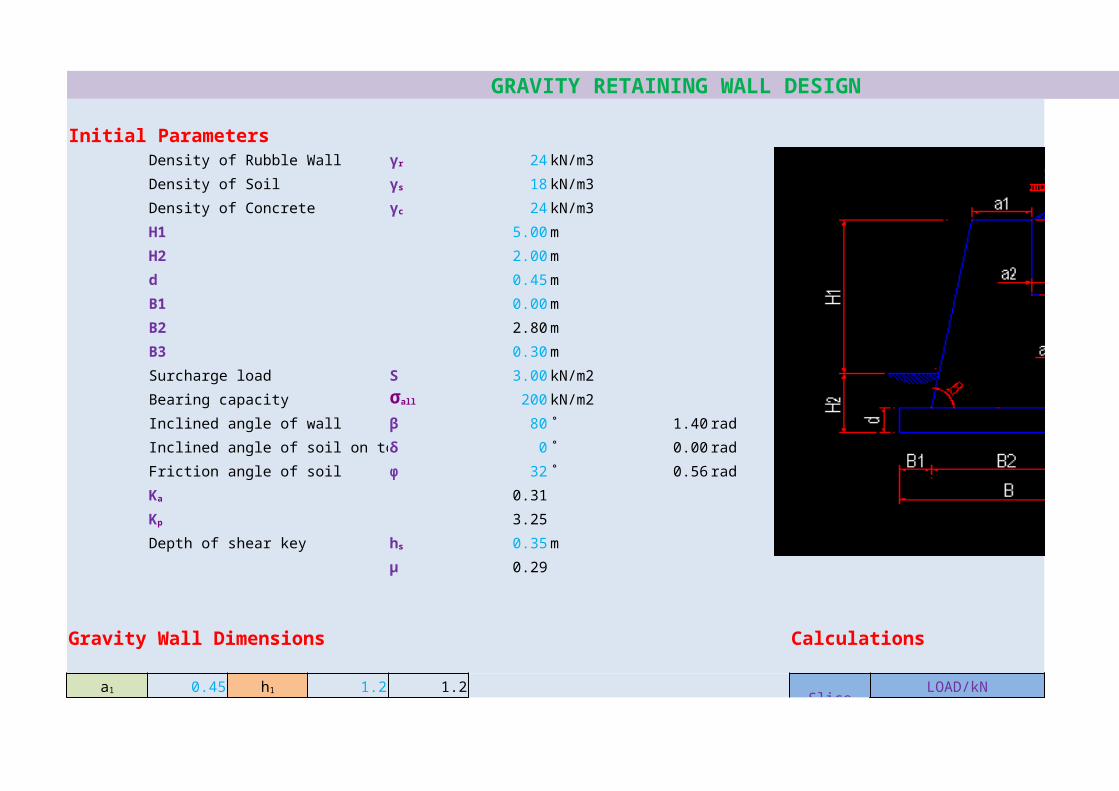
H1 5.00 m
H2 2.00 m
d 0.45 m
B1 0.00 m
B2 2.80 m
B3 0.30 m
Surcharge load S 3.00 kN/m2
Bearing capacity 200 kN/m2
Inclined angle of wall β 80 ˚ 1.40 rad
Inclined angle of soil on top δ 0 ˚ 0.00 rad
Friction angle of soil φ 32 ˚ 0.56 rad
0.31
3.25
Depth of shear key 0.35 m
μ 0.29
Gravity Wall Dimensions Calculations
0.45 1.2 1.2 Slice LOAD/kN x Moments / kNm
γr
γs
γc
σall
Ka
Kp
hs
a1 h1
0.15 0.6 1.8Slice
Wall Soilx
Wall
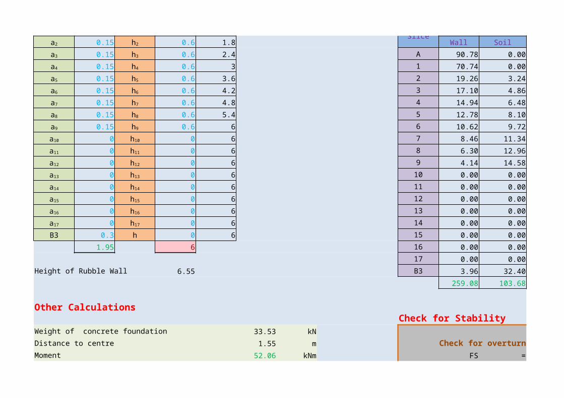
0.15 0.6 2.4 A 90.78 0.00 0.77 69.90
0.15 0.6 3 1 70.74 0.00 1.38 97.62
0.15 0.6 3.6 2 19.26 3.24 1.68 32.36
0.15 0.6 4.2 3 17.10 4.86 1.83 31.29
0.15 0.6 4.8 4 14.94 6.48 1.98 29.58
0.15 0.6 5.4 5 12.78 8.10 2.13 27.22
0.15 0.6 6 6 10.62 9.72 2.28 24.21
0 0 6 7 8.46 11.34 2.43 20.56
0 0 6 8 6.30 12.96 2.58 16.25
0 0 6 9 4.14 14.58 2.73 11.30
0 0 6 10 0.00 0.00 2.80 0.00
0 0 6 11 0.00 0.00 2.80 0.00
0 0 6 12 0.00 0.00 2.80 0.00
0 0 6 13 0.00 0.00 2.80 0.00
0 0 6 14 0.00 0.00 2.80 0.00
B3 0.3 h 0 6 15 0.00 0.00 2.80 0.00
1.95 6 16 0.00 0.00 2.80 0.0017 0.00 0.00 2.80 0.00
Height of Rubble Wall 6.55 B3 3.96 32.40 2.95 11.70
259.08 103.68 371.99
Other CalculationsCheck for Stability
Weight of concrete foundation 33.53 kNDistance to centre 1.55 m Check for overturningMoment 52.06 kNm FS = Sum of stabilizing Moments
a2 h2
a3 h3
a4 h4
a5 h5
a6 h6
a7 h7
a8 h8
a9 h9
a10 h10
a11 h11
a12 h12
a13 h13
a14 h14
a15 h15
a16 h16
a17 h17
Sum of overturning Moments
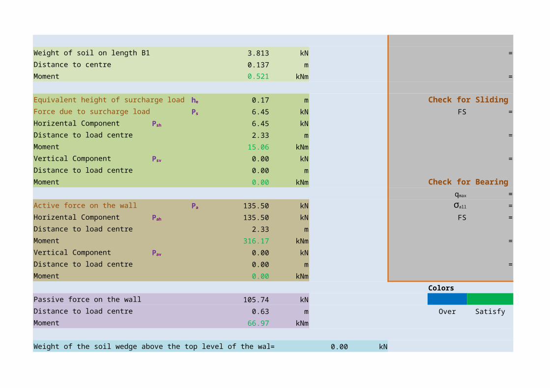
Weight of soil on length B1 3.813 kN = 754.65Distance to centre 0.137 m 331.22Moment 0.521 kNm = 2.28
Equivalent height of surcharge load 0.17 m Check for SlidingForce due to surcharge load 6.45 kN FS = Sum of Resisting ForcesHorizental Component 6.45 kN Sum of Sliding Forces
Distance to load centre 2.33 m = 220.47Moment 15.06 kNm 141.95Vertical Component 0.00 kN = 1.55Distance to load centre 0.00 mMoment 0.00 kNm Check for Bearing Capacity
= 170.27Active force on the wall 135.50 kN = 200Horizental Component 135.50 kN FS = Ultimate Bearing CapacityDistance to load centre 2.33 m Bearing PressureMoment 316.17 kNm =Vertical Component 0.00 kNDistance to load centre 0.00 m = 1.17Moment 0.00 kNm
ColorsPassive force on the wall 105.74 kNDistance to load centre 0.63 m Over Satisfy FailMoment 66.97 kNm
Weight of the soil wedge above the top level of the wall = 0.00 kN
he
Ps
Psh
Psv
qmax kN/m2
Pa σall kN/m2
Pah
σall
Pav qmax

Distance to the load centre from toe = 0.00 mMoment = 0.00 kNm
Friction force along bottom of the concrete base,
F = = 400.10 kN
= 114.73 kN
1.72 m
3.10 m
Resultant in middle thirdBearing pressures under the Foundation
= 87.45
= 170.27
μRv , Rv
Distance to the Resultant Force R from toe, LR
Width of the Concrete Foundation, B
q1 kN/m2
q2 kN/m2

GRAVITY RETAINING WALL DESIGN
Moments / kNm

Soil
0.00
0.00
5.44
8.89
12.83
17.25
22.16
27.56
33.44
39.80
0.00
0.00
0.00
0.00
0.00
0.00
0.00
0.00
95.74
263.11
Sum of stabilizing Moments

Sum of overturning Moments
Sum of Resisting ForcesSum of Sliding Forces
Ultimate Bearing Capacity
Bearing Pressure

GRAVITY RETAINING WALL DESIGN
Initial ParametersDensity of Rubble Wall 22 kN/m3
Density of Soil 18 kN/m3
Density of Concrete 24 kN/m3
H1 3.35 m
H2 0.91 m
d 0.25 m
B1 0.225 m
B2 0.90 m
B3 0.225 m
Surcharge load S 10.00 kN/m2
Bearing capacity 100 kN/m2
Inclined angle of wall β 90 ˚ 1.57 rad
Inclined angle of soil on top δ 0 ˚ 0.00 rad
Friction angle of soil φ 35 ˚ 0.61 rad
0.27
3.69
Depth of shear key 0.00 m
μ 0.32
Gravity Wall Dimensions Calculations
0.45 0.3 0.3 Slice LOAD/kN x Moments / kNm
γr
γs
γc
σall
Ka
Kp
hs
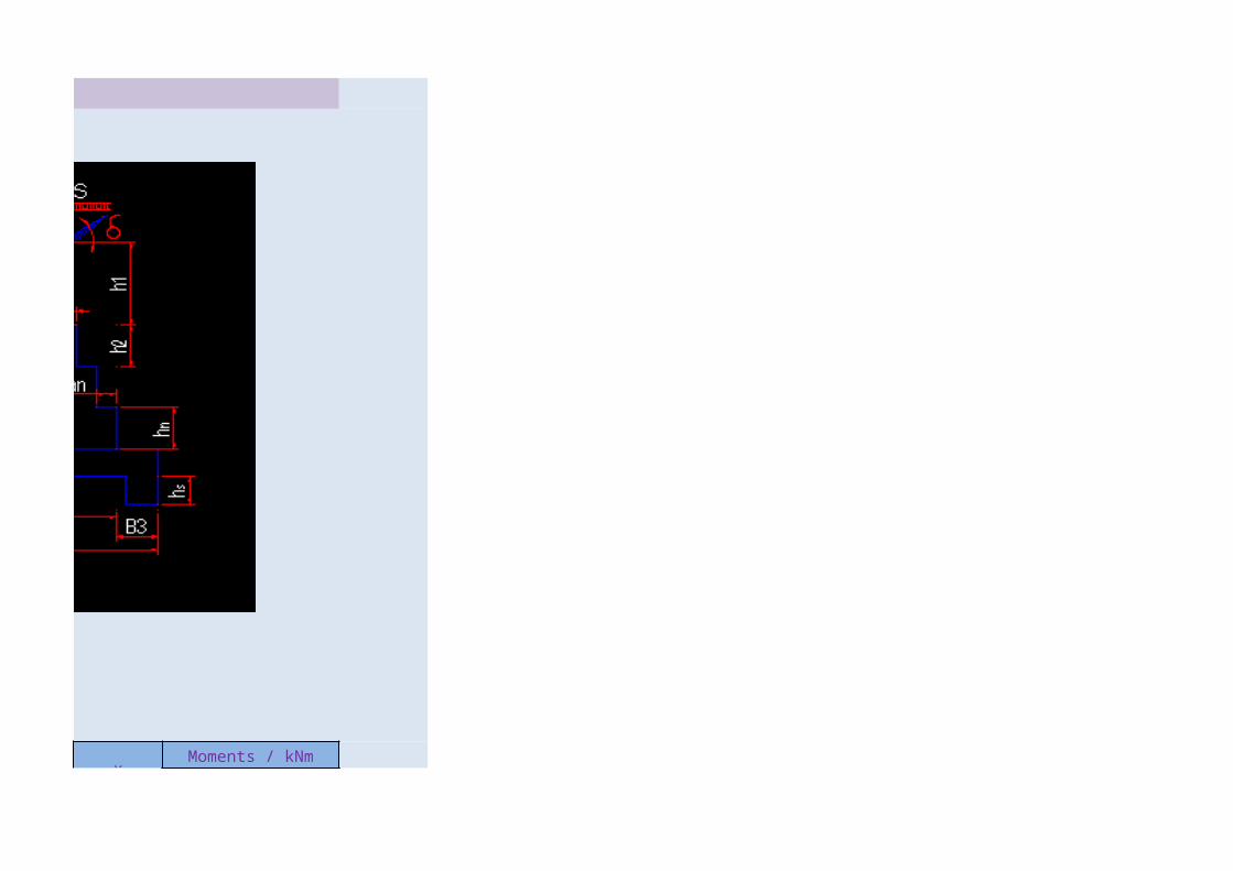
a1 h1
0.225 0.6 0.9Slice
Wall Soilx
Wall
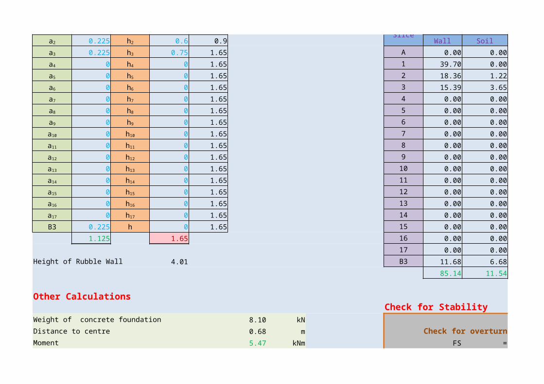
0.225 0.75 1.65 A 0.00 0.00 0.23 0.00
0 0 1.65 1 39.70 0.00 0.45 17.86
0 0 1.65 2 18.36 1.21 0.79 14.46
0 0 1.65 3 15.39 3.64 1.01 15.59
0 0 1.65 4 0.00 0.00 1.13 0.00
0 0 1.65 5 0.00 0.00 1.13 0.00
0 0 1.65 6 0.00 0.00 1.13 0.00
0 0 1.65 7 0.00 0.00 1.13 0.00
0 0 1.65 8 0.00 0.00 1.13 0.00
0 0 1.65 9 0.00 0.00 1.13 0.00
0 0 1.65 10 0.00 0.00 1.13 0.00
0 0 1.65 11 0.00 0.00 1.13 0.00
0 0 1.65 12 0.00 0.00 1.13 0.00
0 0 1.65 13 0.00 0.00 1.13 0.00
0 0 1.65 14 0.00 0.00 1.13 0.00
B3 0.225 h 0 1.65 15 0.00 0.00 1.13 0.00
1.125 1.65 16 0.00 0.00 1.13 0.0017 0.00 0.00 1.13 0.00
Height of Rubble Wall 4.01 B3 11.68 6.68 1.24 14.46
85.14 11.54 62.37
Other CalculationsCheck for Stability
Weight of concrete foundation 8.10 kNDistance to centre 0.68 m Check for overturningMoment 5.47 kNm FS = Sum of stabilizing Moments
a2 h2
a3 h3
a4 h4
a5 h5
a6 h6
a7 h7
a8 h8
a9 h9
a10 h10
a11 h11
a12 h12
a13 h13
a14 h14
a15 h15
a16 h16
a17 h17

Sum of overturning Moments
Weight of soil on length B1 2.673 kN = 82.13Distance to centre 0.113 m 79.24Moment 0.301 kNm = 1.04
Equivalent height of surcharge load 0.56 m Check for SlidingForce due to surcharge load 11.54 kN FS = Sum of Resisting ForcesHorizental Component 11.54 kN Sum of Sliding Forces
Distance to load centre 1.42 m = 40.91Moment 16.39 kNm 55.80Vertical Component 0.00 kN = 0.73Distance to load centre 0.00 mMoment 0.00 kNm Check for Bearing Capacity
= 107.65Active force on the wall 44.26 kN = 100Horizental Component 44.26 kN FS = Ultimate Bearing CapacityDistance to load centre 1.42 m Bearing PressureMoment 62.85 kNm =Vertical Component 0.00 kNDistance to load centre 0.00 m = 0.93Moment 0.00 kNm
ColorsPassive force on the wall 7.03 kNDistance to load centre 0.15 m Over Satisfy FailMoment 1.08 kNm
Weight of the soil wedge above the top level of the wall = 0.00 kN
he
Ps
Psh
Psv
qmax kN/m2
Pa σall kN/m2
Pah
σall
Pav qmax
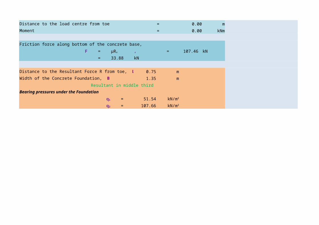
Distance to the load centre from toe = 0.00 mMoment = 0.00 kNm
Friction force along bottom of the concrete base,
F = = 107.46 kN
= 33.88 kN
0.75 m
1.35 m
Resultant in middle thirdBearing pressures under the Foundation
= 51.54
= 107.65
μRv , Rv
Distance to the Resultant Force R from toe, LR
Width of the Concrete Foundation, B
q1 kN/m2
q2 kN/m2
GRAVITY RETAINING WALL DESIGN
Moments / kNm
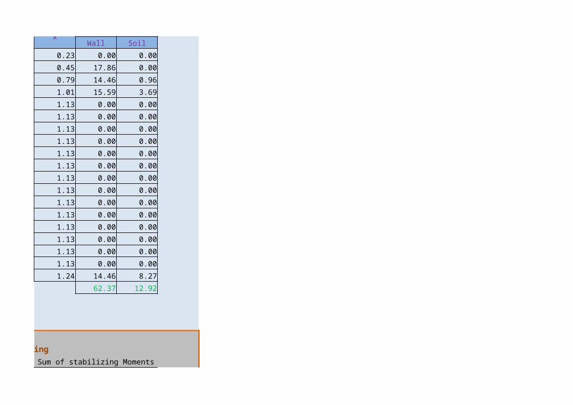
Soil
0.00
0.00
0.96
3.69
0.00
0.00
0.00
0.00
0.00
0.00
0.00
0.00
0.00
0.00
0.00
0.00
0.00
0.00
8.27
12.92
Sum of stabilizing Moments

Sum of overturning Moments
Sum of Resisting ForcesSum of Sliding Forces
Ultimate Bearing Capacity
Bearing Pressure

GRAVITY RETAINING WALL DESIGN
Initial ParametersDensity of Rubble Wall 22 kN/m3
Density of Soil 18 kN/m3
Density of Concrete 22 kN/m3
H1 4.20 m
H2 0.80 m
d 0.20 m
B1 0.25 m
B2 5.07 m
B3 0.25 m
Surcharge load S 5.00 kN/m2
Bearing capacity 150 kN/m2
Inclined angle of wall β 85 ˚ 1.48 rad
Inclined angle of soil on top δ 0 ˚ 0.00 rad
Friction angle of soil φ 30 ˚ 0.52 rad
0.33
3.00
Depth of shear key 0.50 m
μ 0.27
Gravity Wall Dimensions Calculations
0.3 0.6 0.6 Slice LOAD/kN x Moments / kNm
γr
γs
γc
σall
Ka
Kp
hs
a1 h1
0.3 0.6 1.2Slice
Wall Soilx
Wall
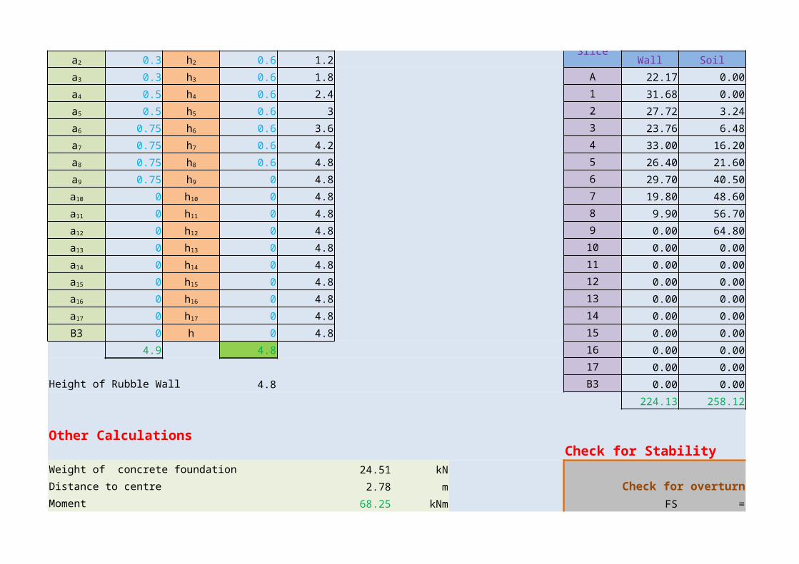
0.3 0.6 1.8 A 22.17 0.00 0.53 11.75
0.5 0.6 2.4 1 31.68 0.00 0.82 25.98
0.5 0.6 3 2 27.72 3.24 1.12 31.04
0.75 0.6 3.6 3 23.76 6.48 1.42 33.74
0.75 0.6 4.2 4 33.00 16.20 1.82 60.06
0.75 0.6 4.8 5 26.40 21.60 2.32 61.25
0.75 0 4.8 6 29.70 40.50 2.94 87.46
0 0 4.8 7 19.80 48.60 3.69 73.16
0 0 4.8 8 9.90 56.70 4.44 44.00
0 0 4.8 9 0.00 64.80 5.19 0.00
0 0 4.8 10 0.00 0.00 5.57 0.00
0 0 4.8 11 0.00 0.00 5.57 0.00
0 0 4.8 12 0.00 0.00 5.57 0.00
0 0 4.8 13 0.00 0.00 5.57 0.00
0 0 4.8 14 0.00 0.00 5.57 0.00
B3 0 h 0 4.8 15 0.00 0.00 5.57 0.00
4.9 4.8 16 0.00 0.00 5.57 0.0017 0.00 0.00 5.57 0.00
Height of Rubble Wall 4.8 B3 0.00 0.00 5.57 0.00
224.13 258.12 428.44
Other CalculationsCheck for Stability
Weight of concrete foundation 24.51 kNDistance to centre 2.78 m Check for overturningMoment 68.25 kNm FS = Sum of stabilizing Moments
a2 h2
a3 h3
a4 h4
a5 h5
a6 h6
a7 h7
a8 h8
a9 h9
a10 h10
a11 h11
a12 h12
a13 h13
a14 h14
a15 h15
a16 h16
a17 h17
Sum of overturning Moments
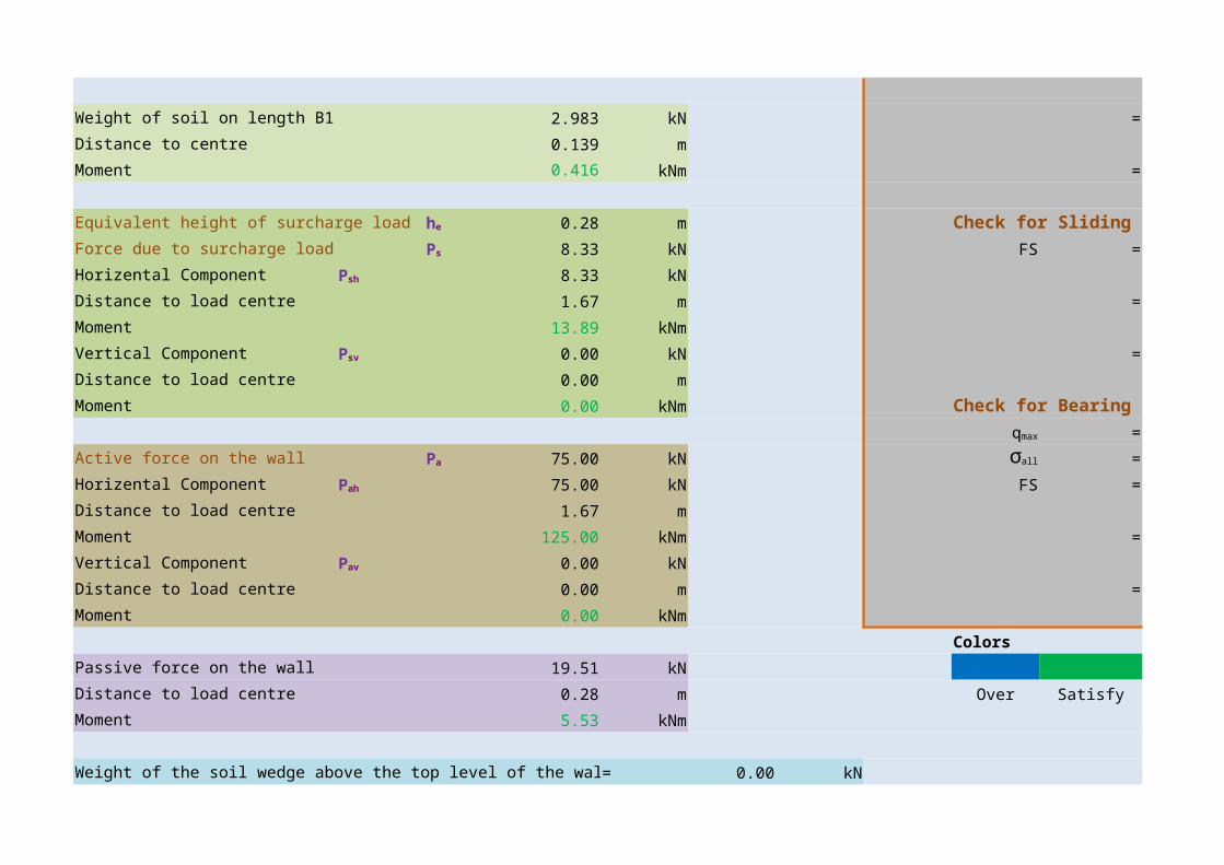
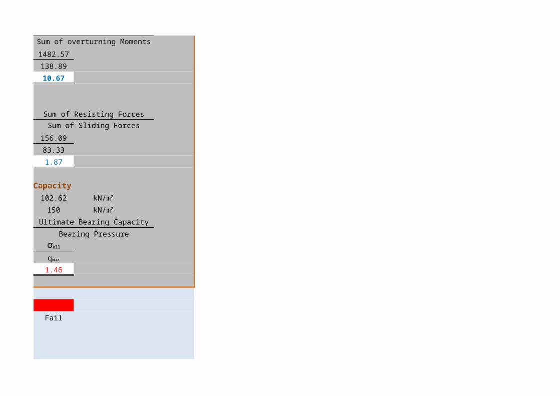
Weight of soil on length B1 2.983 kN = 1482.57Distance to centre 0.139 m 138.89Moment 0.416 kNm = 10.67
Equivalent height of surcharge load 0.28 m Check for SlidingForce due to surcharge load 8.33 kN FS = Sum of Resisting ForcesHorizental Component 8.33 kN Sum of Sliding Forces
Distance to load centre 1.67 m = 156.09Moment 13.89 kNm 83.33Vertical Component 0.00 kN = 1.87Distance to load centre 0.00 mMoment 0.00 kNm Check for Bearing Capacity
= 102.62Active force on the wall 75.00 kN = 150Horizental Component 75.00 kN FS = Ultimate Bearing CapacityDistance to load centre 1.67 m Bearing PressureMoment 125.00 kNm =Vertical Component 0.00 kNDistance to load centre 0.00 m = 1.46Moment 0.00 kNm
ColorsPassive force on the wall 19.51 kNDistance to load centre 0.28 m Over Satisfy FailMoment 5.53 kNm
Weight of the soil wedge above the top level of the wall = 0.00 kN
he
Ps
Psh
Psv
qmax kN/m2
Pa σall kN/m2
Pah
σall
Pav qmax

Distance to the load centre from toe = 0.00 mMoment = 0.00 kNm
Friction force along bottom of the concrete base,
F = = 509.74 kN
= 136.59 kN
2.90 m
5.57 m
Resultant in middle thirdBearing pressures under the Foundation
= 80.41
= 102.62
μRv , Rv
Distance to the Resultant Force R from toe, LR
Width of the Concrete Foundation, B
q1 kN/m2
q2 kN/m2

GRAVITY RETAINING WALL DESIGN
Moments / kNm
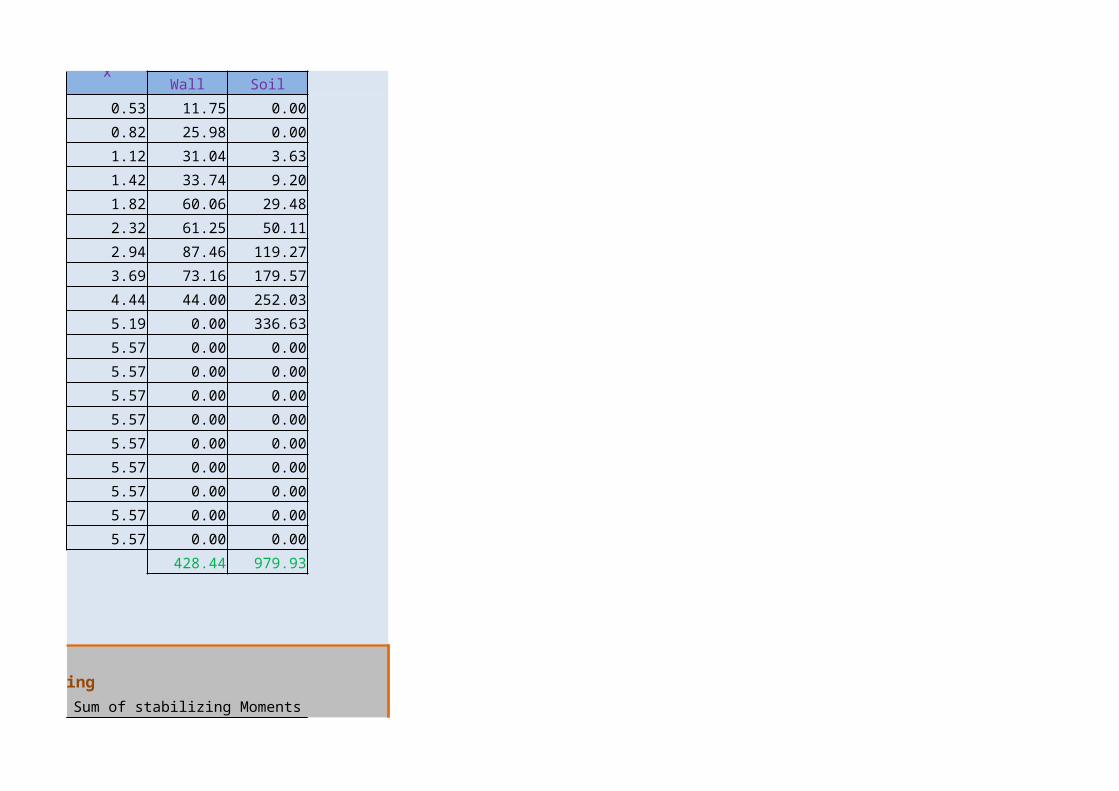
Soil
0.00
0.00
3.63
9.20
29.48
50.11
119.27
179.57
252.03
336.63
0.00
0.00
0.00
0.00
0.00
0.00
0.00
0.00
0.00
979.93
Sum of stabilizing Moments
Sum of overturning Moments
Sum of Resisting ForcesSum of Sliding Forces
Ultimate Bearing Capacity
Bearing Pressure


![Unraveling conformal gravity amplitudesgravity.psu.edu › events › superstring_supergravity › talks › mogull_sstu2018.pdfUnraveling conformal gravity amplitudes based on [1806.05124]](https://static.fdocument.org/doc/165x107/5f0cfc827e708231d4381d0d/unraveling-conformal-gravity-a-events-a-superstringsupergravity-a-talks-a.jpg)