
Grain Code International Code for the Safe Carriage of ... · 2.5. The term angle of flooding (θ1)...
41
Grain Code International Code for the Safe Carriage of Grain in Bulk – Resolution MSC.23(59) Grain Code International Code for the Safe Carriage of Grain in Bulk – Resolution MSC.23(59)
Transcript of Grain Code International Code for the Safe Carriage of ... · 2.5. The term angle of flooding (θ1)...
Grain Code International Code for the Safe Carriage of Grain in Bulk – Resolution MSC.23(59)
Grain Code International Code for the SafeCarriage of Grain in Bulk – ResolutionMSC.23(59)
Grain Code International Code for the Safe Carriage of Grain in Bulk – Resolution MSC.23(59) Part A Specificrequirements
Part A Specific requirements
Grain Code International Code for the Safe Carriage of Grain in Bulk – Resolution MSC.23(59) Part A Specificrequirements 1 Application
1 Application1.1. This Code applies to ships regardless of size, including those of less than 500 tons gross tonnage, engaged in the carriage ofgrain in bulk, to which part C of chapter VI of the 1974 SOLAS Convention, as amended, applies.
1.2. For the purpose of this Code, the expression "ships constructed" means "ships the keels of which are laid or which are at asimilar stage of construction".
Grain Code International Code for the Safe Carriage of Grain in Bulk – Resolution MSC.23(59) Part A Specificrequirements 2 Definitions
2 Definitions2.1. The term grain covers wheat, maize (corn), oats, rye, barley, rice, pulses, seeds and processed forms thereof, whosebehaviour is similar to that of grain in its natural state.
2.2. The term filled compartment, trimmed, refers to any cargo space in which, after loading and trimming as required under A10.2, the bulk grain is at its highest possible level.
2.3. The term filled compartment, untrimmed, refers to a cargo space which is filled to the maximum extent possible in way of thehatch opening but which has not been trimmed outside the periphery of the hatch opening either by the provisions of A 10.3.1 forall ships or A 10.3.2 for specially suitable compartments.
2.4. The term partly filled compartment refers to any cargo space wherein the bulk grain is not loaded in the manner prescribed inA 2.2 or A 2.3.
2.5. The term angle of flooding (θ1) means the angle of heel at which openings in the hull, superstructures or deckhouses, whichcannot be closed weathertight, immerse. In applying this definition, small openings through which progressive flooding cannottake place need not be considered as open.
2.6. The term stowage factor, for the purposes of calculating the grain heeling moment caused by a shift of grain, means thevolume per unit weight of the cargo as attested by the loading facility, i.e. no allowance shall be made for lost space when thecargo space is nominally filled.
2.7. The term specially suitable compartment refers to a cargo space which is constructed with at least two vertical or sloping,longitudinal, graintight divisions which are coincident with the hatch side girders or are so positioned as to limit the effect of anytransverse shift of grain. If sloping, the divisions shall have an inclination of not less than 30° to the horizontal.
Grain Code International Code for the Safe Carriage of Grain in Bulk – Resolution MSC.23(59) Part A Specificrequirements 3 Document of authorization
3 Document of authorization3.1. A document of authorization shall be issued for every ship loaded in accordance with the regulations of this Code either bythe Administration or an organization recognized by it or by a Contracting Government on behalf of the Administration. It shall beaccepted as evidence that the ship is capable of complying with the requirements of these regulations.
3.2. The document shall accompany or be incorporated into the grain loading manual provided to enable the master to meet therequirements of A 7. The manual shall meet the requirements of A 6.3.
3.3. Such a document, grain loading stability data and associated plans may be drawn up in the official language or languages ofthe issuing country. If the language used is neither English nor French, the text shall include a translation into one of theselanguages.
3.4. A copy of such a document, grain loading stability data and associated plans shall be placed on board in order that themaster, if so required, shall produce them for the inspection of the Contracting Government of the country of the port of loading.
3.5. A ship without such a document of authorization shall not load grain until the master demonstrates to the satisfaction of theAdministration, or of the Contracting Government of the port of loading acting on behalf of the Administration, that, in its loadedcondition for the intended voyage, the ship complies with the requirements of this Code. See also A 8.3 and A 9.
Grain Code International Code for the Safe Carriage of Grain in Bulk – Resolution MSC.23(59) Part A Specificrequirements 4 Equivalents
4 Equivalents. Where an equivalent accepted by the Administration in accordance with regulation I/5 of the International Convention for theSafety of Life at Sea, 1974, as amended, is used, particulars shall be included in the document of authorization or in the grainloading manual.
Grain Code International Code for the Safe Carriage of Grain in Bulk – Resolution MSC.23(59) Part A Specificrequirements 5 Exemptions for certain voyages
5 Exemptions for certain voyages. The Administration, or a Contracting Government on behalf of the Administration, may, if it considers that the sheltered natureand conditions of the voyage are such as to render the application of any of the requirements of this Code unreasonable orunnecessary, exempt from those particular requirements individual ships or classes of ships.
Grain Code International Code for the Safe Carriage of Grain in Bulk – Resolution MSC.23(59) Part A Specificrequirements 6 Information regarding ship’s stability and grain loading
6 Information regarding ship’s stability and grain loading6.1. Information in printed booklet form shall be provided to enable the master to ensure that the ship complies with this Codewhen carrying grain in bulk on an international voyage. This information shall include that which is listed in A 6.2 and A 6.3.
6.2. Information which shall be acceptable to the Administration or to a Contracting Government on behalf of the Administrationshall include:
.1. ship’s particulars;
.2. lightship displacement and the vertical distance from the intersection of the moulded base line and midship section to thecentre of gravity (KG);
.3. table of liquid free surface corrections;
.4. capacities and centres of gravity;
.5. curve or table of angle of flooding, where less than 40°, at all permissible displacements;
.6. curves or tables of hydrostatic properties suitable for the range of operating drafts; and
.7. cross curves of stability which are sufficient for the purpose of the requirements in A 7 and which include curves at 12° and40°.
6.3. Information which shall be approved by the Administration or by a Contracting Government on behalf of the Administrationshall include:
.1. curves or tables of volumes, vertical centres of volumes, and assumed volumetric heeling moments for every compartment,filled or partly filled, or combination thereof, including the effects of temporary fittings;
.2. tables or curves of maximum permissible heeling moments for varying displacements and varying vertical centres of gravityto allow the master to demonstrate compliance with the requirements of A 7.1; this requirement shall apply only to ships the keelsof which are laid on or after the entry into force of this Code;
.3. details of the scantlings of any temporary fittings and, where applicable, the provisions necessary to meet the requirementsof A 7, A 8 and A 9;
.4. loading instructions in the form of notes summarizing the requirements of this Code;
.5. a worked example for the guidance of the master; and
.6. typical loaded service departure and arrival conditions and where necessary intermediate worst service conditions. seefootnote
Grain Code International Code for the Safe Carriage of Grain in Bulk – Resolution MSC.23(59) Part A Specificrequirements 7 Stability requirements
7 Stability requirements7.1. The intact stability characteristics of any ship carrying bulk grain shall be shown to meet, throughout the voyage, at least thefollowing criteria after taking into account in the manner described in part B of this Code and, in figure A 7, the heeling momentsdue to grain shift:
.1. the angle of heel due to the shift of grain shall not be greater than 12° or in the case of ships constructed on or after 1January 1994 the angle at which the deck edge is immersed, whichever is the lesser;
.2. in the statical stability diagram, the net or residual area between the heeling arm curve and the righting arm curve up to theangle of heel of maximum difference between the ordinates of the two curves, or 40° or the angle of flooding (θ1), whichever is theleast, shall in all conditions of loading be not less than 0.075 metreradians; and
.3. the initial metacentric height, after correction for the free surface effects of liquids in tanks, shall be not less than 0.30 m.
7.2. Before loading bulk grain the master shall, if so required by the Contracting Government of the country of the port of loading,demonstrate the ability of the ship at all stages of any voyage to comply with the stability criteria required by this section.
7.3. After loading, the master shall ensure that the ship is upright before proceeding to sea.
Figure A7(1).
Where:
λ0 =
λ40 = 0.8 × λ0;
Stowage factor = volume per unit weight of grain cargo;
Displacement = weight of ship, fuel, fresh water, stores etc. and cargo.
(2). The righting arm curve shall be derived from crosscurves which are sufficient in number to accurately define the curve for thepurpose of these requirements and shall include crosscurves at 12° and 40°.
Grain Code International Code for the Safe Carriage of Grain in Bulk – Resolution MSC.23(59) Part A Specificrequirements 8 Stability requirements for existing ships
8 Stability requirements for existing ships8.1. For the purposes of this section the term existing ship means a ship, the keel of which is laid before 25 May 1980.
8.2. An existing ship loaded in accordance with documents previously approved under regulation 12 of chapter VI of SOLAS 1960,IMO resolutions A.184(VI) or A.264(VIII) shall be considered to have intact stability characteristics at least equivalent to therequirements of A 7 of this Code. Documents of authorization permitting such loadings shall be accepted for the purposes of A 7.2.
8.3. Existing ships not having on board a document of authorization issued in accordance with A 3 of this Code may apply theprovisions of A 9 without limitation on the deadweight which may be used for the carriage of bulk grain.
Grain Code International Code for the Safe Carriage of Grain in Bulk – Resolution MSC.23(59) Part A Specificrequirements 9 Optional stability requirements for ships without documents of authorization carrying partial cargoes of bulkgrain
9 Optional stability requirements for ships withoutdocuments of authorization carrying partial cargoes of bulkgrain9.1. A ship not having on board a document of authorization issued in accordance with A 3 of this Code may be permitted to loadbulk grain provided that:
.1. the total weight of the bulk grain shall not exceed one third of the deadweight of the ship;
.2. all filled compartments, trimmed, shall be fitted with centreline divisions extending, for the full length of such compartments,downwards from the underside of the deck or hatch covers to a distance below the deck line of at least one eighth of the maximumbreadth of the compartment or 2.4 m, whichever is the greater, except that saucers constructed in accordance with A 14 may beaccepted in lieu of a centreline division in and beneath a hatchway except in the case of linseed and other seeds having similarproperties;
.3. all hatches to filled compartments, trimmed, shall be closed and covers secured in place;
.4. all free grain surfaces in partly filled cargo space shall be trimmed level and secured in accordance with A 16, A 17 or A 18;
.5. throughout the voyage the metacentric height after correction for the free surface effects of liquids in tanks shall be 0.3 m orthat given by the following formula, whichever is the greater:
Where:
L = total combined length of all full compartments (metres)
B = moulded breadth of the vessel (metres)
SF = stowage factor (cubic metres per tonne)
Vd = calculated average void depth calculated in accordance with B 1 (metres Note: not millimetres)
Δ = displacement (tonnes); and
.6. the master demonstrates to the satisfaction of the Administration or the Contracting Government of the port of loading onbehalf of the Administration that the ship in its proposed loaded condition will comply with the requirements of this section.
Grain Code International Code for the Safe Carriage of Grain in Bulk – Resolution MSC.23(59) Part A Specificrequirements 10 Stowage of bulk grain
10 Stowage of bulk grain10.1. All necessary and reasonable trimming shall be performed to level all free grain surfaces and to minimize the effect of grainshifting.
10.2. In any filled compartment, trimmed, the bulk grain shall be trimmed so as to fill all spaces under the decks and hatch coversto the maximum extent possible.
10.3. In any filled compartment, untrimmed, the bulk grain shall be filled to the maximum extent possible in way of the hatchopening but may be at its natural angle of repose outside the periphery of the hatch opening. A filled compartment may qualify forthis classification if it falls into one of the following categories:
.1. the Administration issuing the document of authorization may, under B 6, grant dispensation from trimming in those caseswhere the underdeck void geometry resulting from free flowing grain into a compartment, which may be provided with feederducts, perforated decks or other similar means, is taken into account when calculating the void depths; or
.2. the compartment is "specially suitable" as defined in A 2.7, in which case dispensation may be granted from trimming theends of that compartment.
10.4. If there is no bulk grain or other cargo above a lower cargo space containing grain, the hatch covers shall be secured in anapproved manner having regard to the mass and permanent arrangements provided for securing such covers.
10.5. When bulk grain is stowed on top of closed ’tweendeck hatch covers which are not graintight, such covers shall be madegraintight by taping the joints, covering the entire hatchway with tarpaulins or separation cloths, or other suitable means.
10.6. After loading, all free grain surfaces in partly filled compartments shall be level.
10.7. Unless account is taken of the adverse heeling effect due to the grain shift according to this Code, the surface of the bulkgrain in any partly filled compartment shall be secured so as to prevent a grain shift by overstowing as described in A 16.Alternatively, in partly filled compartments, the bulk grain surface may be secured by strapping or lashing as described in A 17 orA 18.
10.8. Lower cargo spaces and ’tweendeck spaces in way thereof may be loaded as one compartment provided that, incalculating transverse heeling moments, proper account is taken of the flow of grain into the lower spaces.
10.9. In filled compartments, trimmed; filled compartments, untrimmed; and partly filled compartments, longitudinal divisions maybe installed as a device to reduce the adverse heeling effect of grain shift provided that:
.1. the division is graintight;
.2. the construction meets the requirements of A 11, A 12 and A 13; and
.3. in ’tweendecks the division extends from deck to deck and in other cargo spaces the division extends downwards from theunderside of the deck or hatch covers, as described in B 2.8.2, note (2); B 2.9.2, note (3); or B 5.2, as applicable.
Grain Code International Code for the Safe Carriage of Grain in Bulk – Resolution MSC.23(59) Part A Specificrequirements 11 Strength of grain fittings
11 Strength of grain fittings11.1 Timber. All timber used for grain fittings shall be of good sound quality and of a type and grade which has been proved to be satisfactoryfor this purpose. The actual finished dimensions of the timber shall be in accordance with the dimensions specified below.Plywood of an exterior type bonded with waterproof glue and fitted so that the direction of the grain in the face plies isperpendicular to the supporting uprights or binder may be used provided that its strength is equivalent to that of solid timber of theappropriate scantlings.
11.2 Working stresses. When calculating the dimensions of divisions loaded on one side, using tables A 131 to A 136, the following working stressesshould be adopted:
. For divisions of steel: 19.6 kN/cm2
. For divisions of wood: 1.57 kN/cm2
. (1 newton is equivalent to 0.102 kilograms).
11.3 Other materials. Materials other than wood or steel may be approved for such divisions provided that proper regard has been paid to theirmechanical properties.
11.4 Uprights.1. Unless means are provided to prevent the ends of uprights being dislodged from their sockets, the depth of housing at eachend of each upright shall be not less than 75 mm. If an upright is not secured at the top, the uppermost shore or stay shall be fittedas near thereto as is practicable.
.2. The arrangements provided for inserting shifting boards by removing a part of the crosssection of an upright shall be such thatthe local level of stresses is not unduly high.
.3. The maximum bending moment imposed upon an upright supporting a division loaded on one side shall normally becalculated assuming that the ends of the uprights are freely supported. However, if an Administration is satisfied that any degree offixity assumed will be achieved in practice, account may be taken of any reduction in the maximum bending moment arising fromany degree of fixity provided at the ends of the upright.
11.5 Composite section. Where uprights, binders or any other strength members are formed by two separate sections, one fitted on each side of a divisionand interconnected by through bolts at adequate spacing, the effective section modulus shall be taken as the sum of the twomoduli of the separate sections.
11.6 Partial division. Where divisions do not extend to the full depth of the cargo space such divisions and their uprights shall be supported or stayedso as to be as efficient as those which do extend to the full depth of the cargo space.
Grain Code International Code for the Safe Carriage of Grain in Bulk – Resolution MSC.23(59) Part A Specificrequirements 12 Divisions loaded on both sides
12 Divisions loaded on both sides
Grain Code International Code for the Safe Carriage of Grain in Bulk – Resolution MSC.23(59) Part A Specificrequirements 12 Divisions loaded on both sides 12.1 Shifting boards
12.1 Shifting boards.1. Shifting boards shall have a thickness of not less than 50 mm and shall be fitted graintight and where necessary supported byuprights.
.2. The maximum unsupported span for shifting boards of various thicknesses shall be as follows:
ThicknessMaximum unsupported span50 mm 2.5 m60 mm 3.0 m70 mm 3.5 m80 mm 4.0 m
. If thicknesses greater than these are provided the maximum unsupported span will vary directly with the increase in thickness.
.3. The ends of all shifting boards shall be securely housed with 75 mm minimum bearing length.
Grain Code International Code for the Safe Carriage of Grain in Bulk – Resolution MSC.23(59) Part A Specificrequirements 12 Divisions loaded on both sides 12.2 Other materials
12.2 Other materials. Divisions formed by using materials other than wood shall have a strength equivalent to the shifting boards required in A 12.1.
Grain Code International Code for the Safe Carriage of Grain in Bulk – Resolution MSC.23(59) Part A Specificrequirements 12 Divisions loaded on both sides 12.3 Uprights
12.3 Uprights.1. Steel uprights used to support divisions loaded on both sides shall have a section modulus given by
Where:
W = section modulus in cubic centimetres
a = horizontal span between uprights in metres.
The section modulus per metre span W1 shall be not less than that given by the formula:
Where:
h1 is the vertical unsupported span in metres and shall be taken as the maximum value of the distance betweenany two adjacent stays or between a stay and either end of the upright. Where this distance is less than 2.4 m therespective modulus shall be calculated as if the actual value were 2.4 m.
.2. The moduli of wood uprights shall be determined by multiplying by 12.5 the corresponding moduli for steel uprights. If othermaterials are used their moduli shall be at least that required for steel increased in proportion to the ratio of the permissiblestresses for steel to that of the material used. In such cases attention shall be paid also to the relative rigidity of each upright toensure that the deflection is not excessive.
.3. The horizontal distance between uprights shall be such that the unsupported spans of the shifting boards do not exceed themaximum span specified in A 12.1.2.
Grain Code International Code for the Safe Carriage of Grain in Bulk – Resolution MSC.23(59) Part A Specificrequirements 12 Divisions loaded on both sides 12.4 Shores
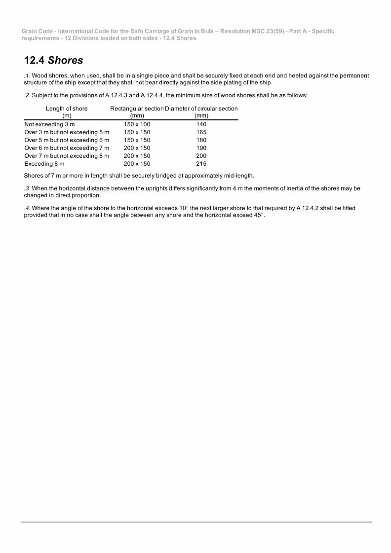
12.4 Shores.1. Wood shores, when used, shall be in a single piece and shall be securely fixed at each end and heeled against the permanentstructure of the ship except that they shall not bear directly against the side plating of the ship.
.2. Subject to the provisions of A 12.4.3 and A 12.4.4, the minimum size of wood shores shall be as follows:
Length of shore(m)
Rectangular section(mm)
Diameter of circular section(mm)
Not exceeding 3 m 150 x 100 140Over 3 m but not exceeding 5 m 150 x 150 165Over 5 m but not exceeding 6 m 150 x 150 180Over 6 m but not exceeding 7 m 200 x 150 190Over 7 m but not exceeding 8 m 200 x 150 200Exceeding 8 m 200 x 150 215
Shores of 7 m or more in length shall be securely bridged at approximately midlength.
.3. When the horizontal distance between the uprights differs significantly from 4 m the moments of inertia of the shores may bechanged in direct proportion.
.4. Where the angle of the shore to the horizontal exceeds 10° the next larger shore to that required by A 12.4.2 shall be fittedprovided that in no case shall the angle between any shore and the horizontal exceed 45°.
Grain Code International Code for the Safe Carriage of Grain in Bulk – Resolution MSC.23(59) Part A Specificrequirements 12 Divisions loaded on both sides 12.5 Stays
12.5 Stays. Where stays are used to support divisions loaded on both sides, they shall be fitted horizontally or as near thereto as practicable,well secured at each end and formed of steel wire rope. The sizes of the wire rope shall be determined assuming that the divisionsand upright which the stay supports are uniformly loaded at 4.9 kN/m2. The working load so assumed in the stay shall not exceedone third of its breaking load.
Grain Code International Code for the Safe Carriage of Grain in Bulk – Resolution MSC.23(59) Part A Specificrequirements 13 Divisions loaded on one side only
13 Divisions loaded on one side only
Grain Code International Code for the Safe Carriage of Grain in Bulk – Resolution MSC.23(59) Part A Specificrequirements 13 Divisions loaded on one side only 13.1 Longitudinal divisions
13.1 Longitudinal divisions. The load (P) in kilonewtons per metre length of the divisions shall be taken as follows:
.1. Table A 131
.2. Linear interpolation within table A 131 may be used for intermediate values of B and for intermediate values of h when h isequal to or less than 6.0 m.
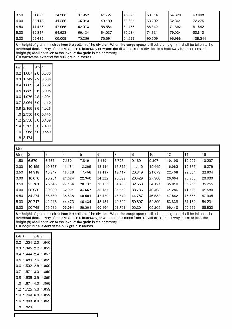
.3. For values of h exceeding 6.0 m the load (P) in kilonewtons per metre length of the divisions may be determined from tableA 132 by entering with the ratio B/h and utilizing the formula:
.4. Table A 132
Grain Code International Code for the Safe Carriage of Grain in Bulk – Resolution MSC.23(59) Part A Specificrequirements 13 Divisions loaded on one side only 13.2 Transverse divisions
13.2 Transverse divisions. The load (P) in kilonewtons per metre length of the divisions shall be taken as follows:
.1. Table A 133
.2. Intermediate values of L and intermediate values of h when h is equal to or less than 6.0 m may be determined by linearinterpolation using table A 133.
.3. For values of h exceeding 6.0 m the load (P) in kilonewtons per metre length of the divisions may be determined from tableA 134 by entering with the ratio L/h and utilizing the formula:
.4. Table A 134
Grain Code International Code for the Safe Carriage of Grain in Bulk – Resolution MSC.23(59) Part A Specificrequirements 13 Divisions loaded on one side only 13.3
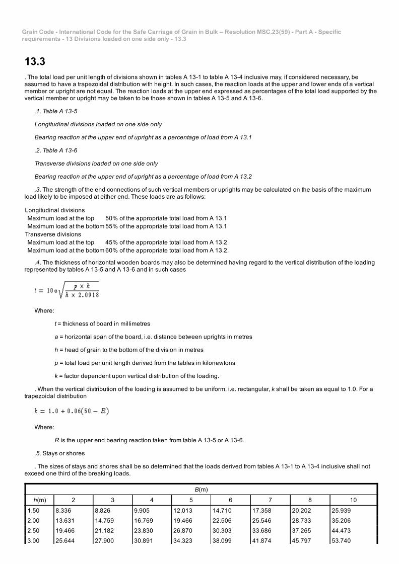
13.3. The total load per unit length of divisions shown in tables A 131 to table A 134 inclusive may, if considered necessary, beassumed to have a trapezoidal distribution with height. In such cases, the reaction loads at the upper and lower ends of a verticalmember or upright are not equal. The reaction loads at the upper end expressed as percentages of the total load supported by thevertical member or upright may be taken to be those shown in tables A 135 and A 136.
.1. Table A 135
Longitudinal divisions loaded on one side only
Bearing reaction at the upper end of upright as a percentage of load from A 13.1
.2. Table A 136
Transverse divisions loaded on one side only
Bearing reaction at the upper end of upright as a percentage of load from A 13.2
.3. The strength of the end connections of such vertical members or uprights may be calculated on the basis of the maximumload likely to be imposed at either end. These loads are as follows:
Longitudinal divisions Maximum load at the top 50% of the appropriate total load from A 13.1 Maximum load at the bottom55% of the appropriate total load from A 13.1Transverse divisions Maximum load at the top 45% of the appropriate total load from A 13.2 Maximum load at the bottom60% of the appropriate total load from A 13.2.
.4. The thickness of horizontal wooden boards may also be determined having regard to the vertical distribution of the loadingrepresented by tables A 135 and A 136 and in such cases
Where:
t = thickness of board in millimetres
a = horizontal span of the board, i.e. distance between uprights in metres
h = head of grain to the bottom of the division in metres
p = total load per unit length derived from the tables in kilonewtons
k = factor dependent upon vertical distribution of the loading.
. When the vertical distribution of the loading is assumed to be uniform, i.e. rectangular, k shall be taken as equal to 1.0. For atrapezoidal distribution
Where:
R is the upper end bearing reaction taken from table A 135 or A 136.
.5. Stays or shores
. The sizes of stays and shores shall be so determined that the loads derived from tables A 131 to A 134 inclusive shall notexceed one third of the breaking loads.
B(m)
h(m) 2 3 4 5 6 7 8 10
1.50 8.336 8.826 9.905 12.013 14.710 17.358 20.202 25.939
2.00 13.631 14.759 16.769 19.466 22.506 25.546 28.733 35.206
2.50 19.466 21.182 23.830 26.870 30.303 33.686 37.265 44.473
3.00 25.644 27.900 30.891 34.323 38.099 41.874 45.797 53.740
3.50 31.823 34.568 37.952 41.727 45.895 50.014 54.329 63.008
4.00 38.148 41.286 45.013 49.180 53.691 58.202 62.861 72.275
4.50 44.473 47.955 52.073 56.584 61.488 66.342 71.392 81.542
5.00 50.847 54.623 59.134 64.037 69.284 74.531 79.924 90.810
6.00 63.498 68.009 73.256 78.894 84.877 90.859 96.988 109.344
h = height of grain in metres from the bottom of the division. When the cargo space is filled, the height (h) shall be taken to theoverhead deck in way of the division. In a hatchway or where the distance from a division to a hatchway is 1 m or less, theheight (h) shall be taken to the level of the grain in the hatchway.B = transverse extent of the bulk grain in metres.
B/h f B/h f
0.2 1.687 2.0 3.380
0.3 1.742 2.2 3.586
0.4 1.809 2.4 3.792
0.5 1.889 2.6 3.998
0.6 1.976 2.8 4.204
0.7 2.064 3.0 4.410
0.8 2.159 3.5 4.925
1.0 2.358 4.0 5.440
1.2 2.556 5.0 6.469
1.4 2.762 6.0 7.499
1.6 2.968 8.0 9.559
1.8 3.174
L(m)
h(m) 2 3 4 5 6 7 8 10 12 14 16
1.50 6.570 6.767 7.159 7.649 8.189 8.728 9.169 9.807 10.199 10.297 10.297
2.00 10.199 10.787 11.474 12.209 12.994 13.729 14.416 15.445 16.083 16.279 16.279
2.50 14.318 15.347 16.426 17.456 18.437 19.417 20.349 21.673 22.408 22.604 22.604
3.00 18.878 20.251 21.624 22.948 24.222 25.399 26.429 27.900 28.684 28.930 28.930
3.50 23.781 25.546 27.164 28.733 30.155 31.430 32.558 34.127 35.010 35.255 35.255
4.00 28.930 30.989 32.901 34.667 36.187 37.559 38.736 40.403 41.286 41.531 41.580
4.50 34.274 36.530 38.638 40.501 42.120 43.542 44.767 46.582 47.562 47.856 47.905
5.00 39.717 42.218 44.473 46.434 48.151 49.622 50.897 52.809 53.839 54.182 54.231
6.00 50.749 53.593 56.094 58.301 60.164 61.782 63.204 65.263 66.440 66.832 66.930
h = height of grain in metres from the bottom of the division. When the cargo space is filled, the height (h) shall be taken to theoverhead deck in way of the division. In a hatchway, or where the distance from a division to a hatchway is 1 m or less, theheight (h) shall be taken to the level of the grain in the hatchway.L = longitudinal extent of the bulk grain in metres.
L/h f L/h f
0.2 1.334 2.0 1.846
0.3 1.395 2.2 1.853
0.4 1.444 2.4 1.857
0.5 1.489 2.6 1.859
0.6 1.532 2.8 1.859
0.7 1.571 3.0 1.859
0.8 1.606 3.5 1.859
1.0 1.671 4.0 1.859
1.2 1.725 5.0 1.859
1.4 1.769 6.0 1.859
1.6 1.803 8.0 1.859
1.8 1.829
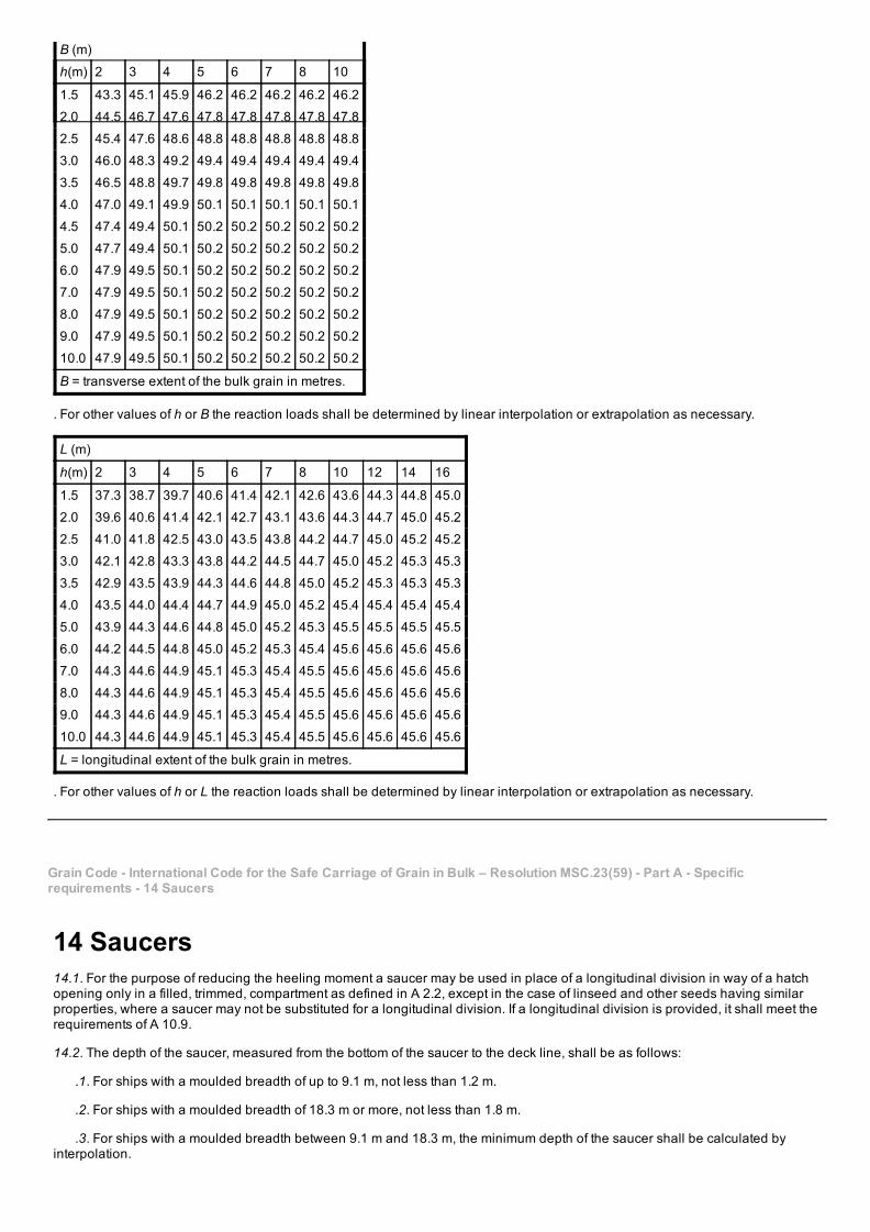
B (m)
h(m) 2 3 4 5 6 7 8 10
1.5 43.3 45.1 45.9 46.2 46.2 46.2 46.2 46.2
2.0 44.5 46.7 47.6 47.8 47.8 47.8 47.8 47.8
2.5 45.4 47.6 48.6 48.8 48.8 48.8 48.8 48.8
3.0 46.0 48.3 49.2 49.4 49.4 49.4 49.4 49.4
3.5 46.5 48.8 49.7 49.8 49.8 49.8 49.8 49.8
4.0 47.0 49.1 49.9 50.1 50.1 50.1 50.1 50.1
4.5 47.4 49.4 50.1 50.2 50.2 50.2 50.2 50.2
5.0 47.7 49.4 50.1 50.2 50.2 50.2 50.2 50.2
6.0 47.9 49.5 50.1 50.2 50.2 50.2 50.2 50.2
7.0 47.9 49.5 50.1 50.2 50.2 50.2 50.2 50.2
8.0 47.9 49.5 50.1 50.2 50.2 50.2 50.2 50.2
9.0 47.9 49.5 50.1 50.2 50.2 50.2 50.2 50.2
10.0 47.9 49.5 50.1 50.2 50.2 50.2 50.2 50.2
B = transverse extent of the bulk grain in metres.
. For other values of h or B the reaction loads shall be determined by linear interpolation or extrapolation as necessary.
L (m)
h(m) 2 3 4 5 6 7 8 10 12 14 16
1.5 37.3 38.7 39.7 40.6 41.4 42.1 42.6 43.6 44.3 44.8 45.0
2.0 39.6 40.6 41.4 42.1 42.7 43.1 43.6 44.3 44.7 45.0 45.2
2.5 41.0 41.8 42.5 43.0 43.5 43.8 44.2 44.7 45.0 45.2 45.2
3.0 42.1 42.8 43.3 43.8 44.2 44.5 44.7 45.0 45.2 45.3 45.3
3.5 42.9 43.5 43.9 44.3 44.6 44.8 45.0 45.2 45.3 45.3 45.3
4.0 43.5 44.0 44.4 44.7 44.9 45.0 45.2 45.4 45.4 45.4 45.4
5.0 43.9 44.3 44.6 44.8 45.0 45.2 45.3 45.5 45.5 45.5 45.5
6.0 44.2 44.5 44.8 45.0 45.2 45.3 45.4 45.6 45.6 45.6 45.6
7.0 44.3 44.6 44.9 45.1 45.3 45.4 45.5 45.6 45.6 45.6 45.6
8.0 44.3 44.6 44.9 45.1 45.3 45.4 45.5 45.6 45.6 45.6 45.6
9.0 44.3 44.6 44.9 45.1 45.3 45.4 45.5 45.6 45.6 45.6 45.6
10.0 44.3 44.6 44.9 45.1 45.3 45.4 45.5 45.6 45.6 45.6 45.6
L = longitudinal extent of the bulk grain in metres.
. For other values of h or L the reaction loads shall be determined by linear interpolation or extrapolation as necessary.
Grain Code International Code for the Safe Carriage of Grain in Bulk – Resolution MSC.23(59) Part A Specificrequirements 14 Saucers
14 Saucers14.1. For the purpose of reducing the heeling moment a saucer may be used in place of a longitudinal division in way of a hatchopening only in a filled, trimmed, compartment as defined in A 2.2, except in the case of linseed and other seeds having similarproperties, where a saucer may not be substituted for a longitudinal division. If a longitudinal division is provided, it shall meet therequirements of A 10.9.
14.2. The depth of the saucer, measured from the bottom of the saucer to the deck line, shall be as follows:
.1. For ships with a moulded breadth of up to 9.1 m, not less than 1.2 m.
.2. For ships with a moulded breadth of 18.3 m or more, not less than 1.8 m.
.3. For ships with a moulded breadth between 9.1 m and 18.3 m, the minimum depth of the saucer shall be calculated byinterpolation.
14.3. The top (mouth) of the saucer shall be formed by the underdeck structure in way of the hatchway, i.e. hatch side girders orcoamings and hatch end beams. The saucer and hatchway above shall be completely filled with bagged grain or other suitablecargo laid down on a separation cloth or its equivalent and stowed tightly against adjacent structure so as to have a bearingcontact with such structure to a depth equal to or greater than one half of the depth specified in A 14.2. If hull structure to providesuch bearing surface is not available, the saucer shall be fixed in position by steel wire rope, chain, or double steel strapping asspecified in A 17.1.4 and spaced not more than 2.4 m apart.
Grain Code International Code for the Safe Carriage of Grain in Bulk – Resolution MSC.23(59) Part A Specificrequirements 15 Bundling of bulk grain
15 Bundling of bulk grain. As an alternative to filling the saucer in a filled, trimmed, compartment with bagged grain or other suitable cargo a bundle of bulkgrain may be used provided that:
.1. The dimensions and means for securing the bundle in place are the same as specified for a saucer in A 14.2 and A 14.3.
.2. The saucer is lined with a material acceptable to the Administration having a tensile strength of not less than 2,687 N per 5cm strip and which is provided with suitable means for securing at the top.
.3. As an alternative to A 15.2, a material acceptable to the Administration having a tensile strength of not less than 1,344 N per5 cm strip may be used if the saucer is constructed as follows:
.3.1. Athwartship lashings acceptable to the Administration shall be placed inside the saucer formed in the bulk grain atintervals of not more than 2.4 m. These lashings shall be of sufficient length to permit being drawn up tight and secured at the topof the saucer.
.3.2. Dunnage not less than 25 mm in thickness or other suitable material of equal strength and between 150 mm and 300mm in width shall be placed fore and aft over these lashings to prevent the cutting or chafing of the material which shall be placedthereon to line the saucer.
.4. The saucer shall be filled with bulk grain and secured at the top except that when using material approved under A 15.3further dunnage shall be laid on top after lapping the material before the saucer is secured by setting up the lashings.
.5. If more than one sheet of material is used to line the saucer they shall be joined at the bottom either by sewing or by adouble lap.
.6. The top of the saucer shall be coincidental with the bottom of the beams when these are in place and suitable generalcargo or bulk grain may be placed between the beams on top of the saucer.
Grain Code International Code for the Safe Carriage of Grain in Bulk – Resolution MSC.23(59) Part A Specificrequirements 16 Overstowing arrangements
16 Overstowing arrangements16.1. Where bagged grain or other suitable cargo is utilized for the purpose of securing partly filled compartments, the free grainsurface shall be level and shall be covered with a separation cloth or equivalent or by a suitable platform. Such platform shallconsist of bearers spaced not more than 1.2 m apart and 25 mm boards laid thereon spaced not more than 100 mm apart.Platforms may be constructed of other materials provided they are deemed by the Administration to be equivalent.
16.2. The platform or separation cloth shall be topped off with bagged grain tightly stowed and extending to a height of not lessthan one sixteenth of the maximum breadth of the free grain surface or 1.2 m, whichever is the greater.
16.3. The bagged grain shall be carried in sound bags which shall be well filled and securely closed.
16.4. Instead of bagged grain, other suitable cargo tightly stowed and exerting at least the same pressure as bagged grain stowedin accordance with A 16.2 may be used.
Grain Code International Code for the Safe Carriage of Grain in Bulk – Resolution MSC.23(59) Part A Specificrequirements 17 Strapping or lashing
17 Strapping or lashing. When, in order to eliminate heeling moments in partly filled compartments, strapping or lashing is utilized, the securing shall beaccomplished as follows:
.1. The grain shall be trimmed and levelled to the extent that it is very slightly crowned and covered with burlap separationcloths, tarpaulins or the equivalent.
.2. The separation cloths and/or tarpaulins shall overlap by at least 1.8 m.
.3. Two solid floors of rough 25 mm x 150 mm to 300 mm lumber shall be laid with the top floor running longitudinally andnailed to an athwartships bottom floor. Alternatively, one solid floor of 50 mm lumber, running longitudinally and nailed over the topof a 50 mm bottom bearer not less than 150 mm wide, may be used. The bottom bearers shall extend the full breadth of thecompartment and shall be spaced not more than 2.4 m apart. Arrangements utilizing other materials and deemed by theAdministration to be equivalent to the foregoing may be accepted.
.4. Steel wire rope (19 mm diameter or equivalent), double steel strapping (50 mm x 1.3 mm and having a breaking load of atleast 49 kN), or chain of equivalent strength, each of which shall be set tightly by means of a 32 mm turnbuckle, may be used for
lashings. A winch tightener, used in conjunction with a locking arm, may be substituted for the 32 mm turnbuckle when steelstrapping is used, provided suitable wrenches are available for setting up as necessary. When steel strapping is used, not lessthan three crimp seals shall be used for securing the ends. When wire is used, not less than four clips shall be used for formingeyes in the lashings.
.5. Prior to the completion of loading the lashing shall be positively attached to the framing at a point approximately 450 mmbelow the anticipated final grain surface by means of either a 25 mm shackle or beam clamp of equivalent strength.
.6. The lashings shall be spaced not more than 2.4 m apart and each shall be supported by a bearer nailed over the top of thefore and aft floor. This bearer shall consist of lumber of not less than 25 mm x 150 mm or its equivalent and shall extend the fullbreadth of the compartment.
.7. During the voyage the strapping shall be regularly inspected and set up where necessary.
Grain Code International Code for the Safe Carriage of Grain in Bulk – Resolution MSC.23(59) Part A Specificrequirements 18 Securing with wire mesh
18 Securing with wire mesh. When, in order to eliminate grain heeling moments in partly filled compartments, strapping or lashing is utilized, the securingmay, as an alternative to the method described in A 17, be accomplished as follows:
.1. The grain shall be trimmed and levelled to the extent that it is very slightly crowned along the fore and aft centreline of thecompartment.
.2. The entire surface of the grain shall be covered with burlap separation cloths, tarpaulins, or the equivalent. The coveringmaterial shall have a tensile strength of not less than 1,344 N per 5 cm strip.
.3. Two layers of wire reinforcement mesh shall be laid on top of the burlap or other covering. The bottom layer is to be laidathwartships and the top layer is to be laid longitudinally. The lengths of wire mesh are to be overlapped at least 75 mm. The toplayer of mesh is to be positioned over the bottom layer in such a manner that the squares formed by the alternate layers measureapproximately 75 mm x 75 mm. The wire reinforcement mesh is the type used in reinforced concrete construction. It is fabricated of3 mm diameter steel wire having a breaking strength of not less than 52 kN/cm2 welded in 150 mm x 150 mm squares. Wire meshhaving mill scale may be used but mesh having loose, flaking rust may not be used.
.4. The boundaries of the wire mesh, at the port and starboard side of the compartment, shall be retained by wood planks 150mm x 50 mm.
.5. Holddown lashings, running from side to side across the compartment, shall be spaced not more than 2.4 m apart exceptthat the first and the last lashing shall not be more than 300 mm from the forward or after bulkhead, respectively. Prior to thecompletion of the loading, each lashing shall be positively attached to the framing at a point approximately 450 mm below theanticipated final grain surface by means of either a 25 mm shackle or beam clamp of equivalent strength. The lashing shall be ledfrom this point over the top of the boundary plank described in A 18.1.4, which has the function of distributing the downwardpressure exerted by the lashing. Two layers of 150 mm x 25 mm planks shall be laid athwartships centred beneath each lashingand extending the full breadth of the compartment.
.6. The holddown lashings shall consist of steel wire rope (19 mm diameter or equivalent), double steel strapping (50 mm x1.3 mm and having a breaking load of at least 49 kN), or chain of equivalent strength, each of which shall be set tight by means ofa 32 mm turnbuckle. A winch tightener, used in conjunction with a locking arm, may be substituted for the 32 mm turnbuckle whensteel strapping is used, provided suitable wrenches are available for setting up as necessary. When steel strapping is used, notless than three crimp seals shall be used for securing the ends. When wire rope is used, not less than four clips shall be used forforming eyes in the lashings.
.7. During the voyage the holddown lashings shall be regularly inspected and set up where necessary.
Grain Code International Code for the Safe Carriage of Grain in Bulk – Resolution MSC.23(59) Part B Calculation ofassumed heeling moments and general assumptions
Part B Calculation of assumed heeling moments andgeneral assumptions
Grain Code International Code for the Safe Carriage of Grain in Bulk – Resolution MSC.23(59) Part B Calculation ofassumed heeling moments and general assumptions 1 General assumptions
1 General assumptions1.1. For the purpose of calculating the adverse heeling moment due to a shift of cargo surface in ships carrying bulk grain it shallbe assumed that:
.1. In filled compartments which have been trimmed in accordance with A 10.2, a void exists under all boundary surfaceshaving an inclination to the horizontal less than 30° and that the void is parallel to the boundary surface having an average depthcalculated according to the formula:
Where:
Vd = average void depth in millimetres
Vd1 = standard void depth from table B 11 below
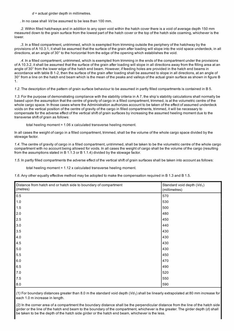
d = actual girder depth in millimetres.
. In no case shall Vd be assumed to be less than 100 mm.
.2. Within filled hatchways and in addition to any open void within the hatch cover there is a void of average depth 150 mmmeasured down to the grain surface from the lowest part of the hatch cover or the top of the hatch side coaming, whichever is thelower.
.3. In a filled compartment, untrimmed, which is exempted from trimming outside the periphery of the hatchway by theprovisions of A 10.3.1, it shall be assumed that the surface of the grain after loading will slope into the void space underdeck, in alldirections, at an angle of 30° to the horizontal from the edge of the opening which establishes the void.
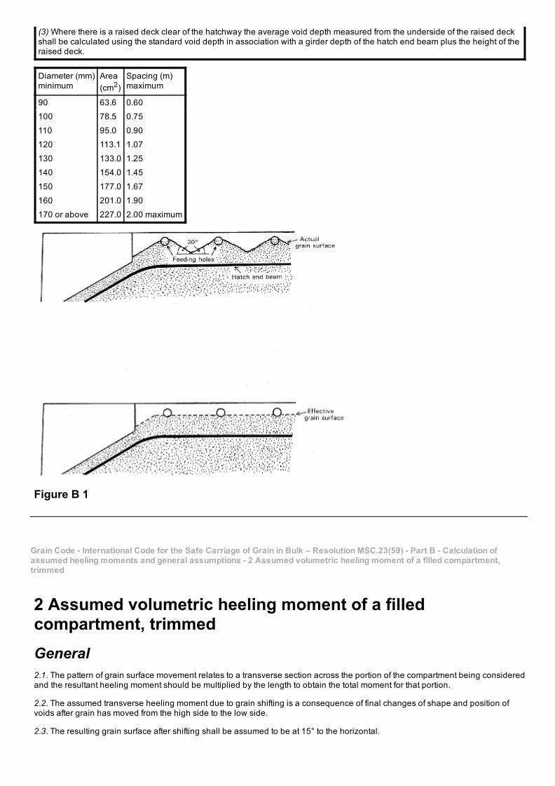
.4. In a filled compartment, untrimmed, which is exempted from trimming in the ends of the compartment under the provisionsof A 10.3.2, it shall be assumed that the surface of the grain after loading will slope in all directions away from the filling area at anangle of 30° from the lower edge of the hatch end beam. However, if feeding holes are provided in the hatch end beams inaccordance with table B 12, then the surface of the grain after loading shall be assumed to slope in all directions, at an angle of30° from a line on the hatch end beam which is the mean of the peaks and valleys of the actual grain surface as shown in figure B1.
1.2. The description of the pattern of grain surface behaviour to be assumed in partly filled compartments is contained in B 5.
1.3. For the purpose of demonstrating compliance with the stability criteria in A 7, the ship’s stability calculations shall normally bebased upon the assumption that the centre of gravity of cargo in a filled compartment, trimmed, is at the volumetric centre of thewhole cargo space. In those cases where the Administration authorizes account to be taken of the effect of assumed underdeckvoids on the vertical position of the centre of gravity of the cargo in filled compartments, trimmed, it will be necessary tocompensate for the adverse effect of the vertical shift of grain surfaces by increasing the assumed heeling moment due to thetransverse shift of grain as follows:
total heeling moment = 1.06 x calculated transverse heeling moment.
In all cases the weight of cargo in a filled compartment, trimmed, shall be the volume of the whole cargo space divided by thestowage factor.
1.4. The centre of gravity of cargo in a filled compartment, untrimmed, shall be taken to be the volumetric centre of the whole cargocompartment with no account being allowed for voids. In all cases the weight of cargo shall be the volume of the cargo (resultingfrom the assumptions stated in B 1.1.3 or B 1.1.4) divided by the stowage factor.
1.5. In partly filled compartments the adverse effect of the vertical shift of grain surfaces shall be taken into account as follows:
total heeling moment = 1.12 x calculated transverse heeling moment.
1.6. Any other equally effective method may be adopted to make the compensation required in B 1.3 and B 1.5.
Distance from hatch end or hatch side to boundary of compartment(metres)
Standard void depth (Vd1)(millimetres)
0.5 570
1.0 530
1.5 500
2.0 480
2.5 450
3.0 440
3.5 430
4.0 430
4.5 430
5.0 430
5.5 450
6.0 470
6.5 490
7.0 520
7.5 550
8.0 590
(1) For boundary distances greater than 8.0 m the standard void depth (Vd1) shall be linearly extrapolated at 80 mm increase foreach 1.0 m increase in length.
(2) In the corner area of a compartment the boundary distance shall be the perpendicular distance from the line of the hatch sidegirder or the line of the hatch end beam to the boundary of the compartment, whichever is the greater. The girder depth (d) shallbe taken to be the depth of the hatch side girder or the hatch end beam, whichever is the less.
(3) Where there is a raised deck clear of the hatchway the average void depth measured from the underside of the raised deckshall be calculated using the standard void depth in association with a girder depth of the hatch end beam plus the height of theraised deck.
Diameter (mm)minimum
Area(cm2)
Spacing (m)maximum
90 63.6 0.60
100 78.5 0.75
110 95.0 0.90
120 113.1 1.07
130 133.0 1.25
140 154.0 1.45
150 177.0 1.67
160 201.0 1.90
170 or above 227.0 2.00 maximum
Figure B 1
Grain Code International Code for the Safe Carriage of Grain in Bulk – Resolution MSC.23(59) Part B Calculation ofassumed heeling moments and general assumptions 2 Assumed volumetric heeling moment of a filled compartment,trimmed
2 Assumed volumetric heeling moment of a filledcompartment, trimmedGeneral2.1. The pattern of grain surface movement relates to a transverse section across the portion of the compartment being consideredand the resultant heeling moment should be multiplied by the length to obtain the total moment for that portion.
2.2. The assumed transverse heeling moment due to grain shifting is a consequence of final changes of shape and position ofvoids after grain has moved from the high side to the low side.
2.3. The resulting grain surface after shifting shall be assumed to be at 15° to the horizontal.
2.4. In calculating the maximum void area that can be formed against a longitudinal structural member, the effects of anyhorizontal surfaces, e.g. flanges or face bars, shall be ignored.
2.5. The total areas of the initial and final voids shall be equal.
2.6. Longitudinal structural members which are graintight may be considered effective over their full depth except where they areprovided as a device to reduce the adverse effect of grain shift, in which case the provisions of A 10.9 shall apply.
2.7. A discontinuous longitudinal division may be considered effective over its full length.
Assumptions. In the following paragraphs it is assumed that the total heeling moment for a compartment is obtained by adding the results ofseparate consideration of the following portions:
2.8. Before and abaft hatchways:
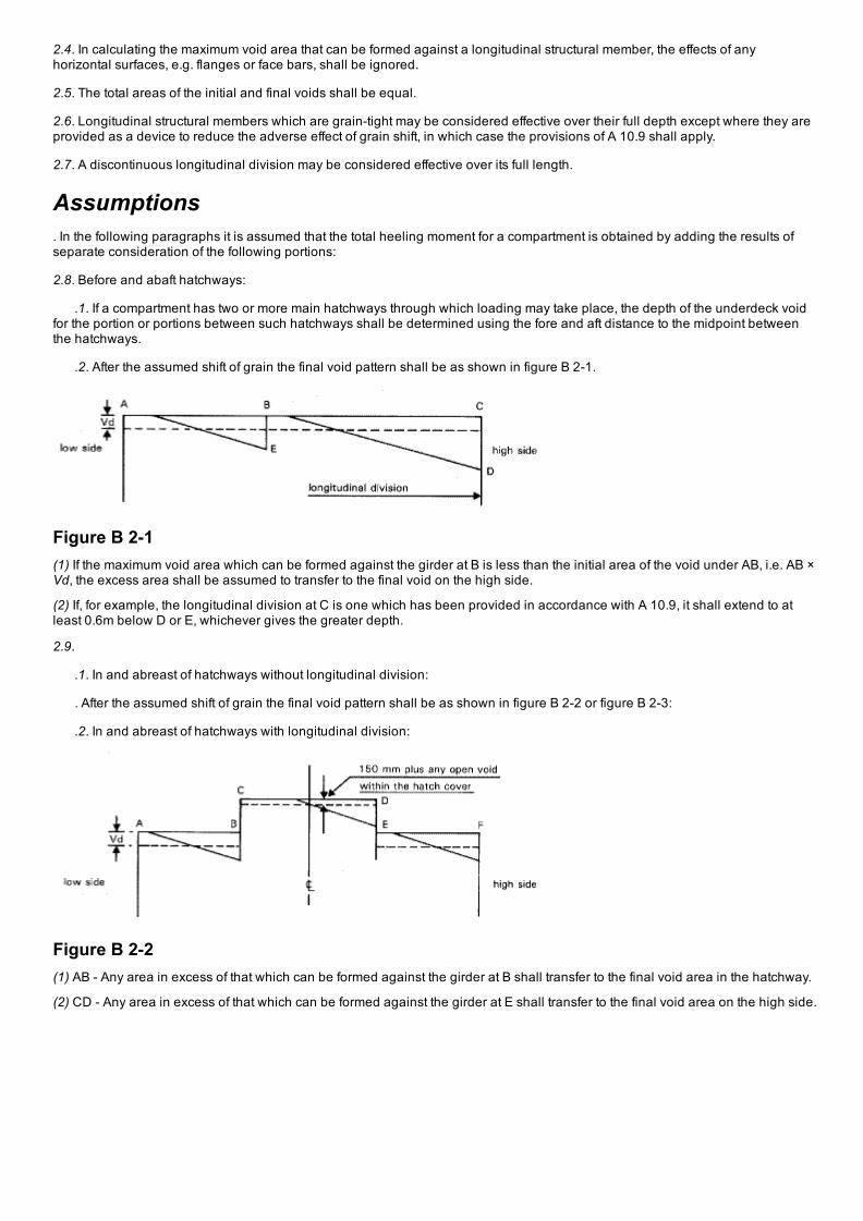
.1. If a compartment has two or more main hatchways through which loading may take place, the depth of the underdeck voidfor the portion or portions between such hatchways shall be determined using the fore and aft distance to the midpoint betweenthe hatchways.
.2. After the assumed shift of grain the final void pattern shall be as shown in figure B 21.
Figure B 21(1) If the maximum void area which can be formed against the girder at B is less than the initial area of the void under AB, i.e. AB ×Vd, the excess area shall be assumed to transfer to the final void on the high side.
(2) If, for example, the longitudinal division at C is one which has been provided in accordance with A 10.9, it shall extend to atleast 0.6m below D or E, whichever gives the greater depth.
2.9.
.1. In and abreast of hatchways without longitudinal division:
. After the assumed shift of grain the final void pattern shall be as shown in figure B 22 or figure B 23:
.2. In and abreast of hatchways with longitudinal division:
Figure B 22(1) AB Any area in excess of that which can be formed against the girder at B shall transfer to the final void area in the hatchway.
(2) CD Any area in excess of that which can be formed against the girder at E shall transfer to the final void area on the high side.
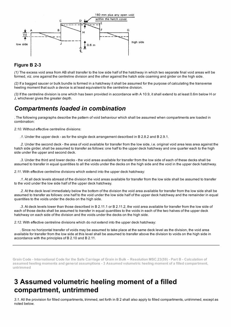
Figure B 23(1) The excess void area from AB shall transfer to the low side half of the hatchway in which two separate final void areas will beformed, viz. one against the centreline division and the other against the hatch side coaming and girder on the high side.
(2) If a bagged saucer or bulk bundle is formed in a hatchway it shall be assumed for the purpose of calculating the transverseheeling moment that such a device is at least equivalent to the centreline division.
(3) If the centreline division is one which has been provided in accordance with A 10.9, it shall extend to at least 0.6m below H orJ, whichever gives the greater depth.
Compartments loaded in combination. The following paragraphs describe the pattern of void behaviour which shall be assumed when compartments are loaded incombination:
2.10. Without effective centreline divisions:
.1. Under the upper deck as for the single deck arrangement described in B 2.8.2 and B 2.9.1.
.2. Under the second deck the area of void available for transfer from the low side, i.e. original void area less area against thehatch side girder, shall be assumed to transfer as follows: one half to the upper deck hatchway and one quarter each to the highside under the upper and second deck.
.3. Under the third and lower decks the void areas available for transfer from the low side of each of these decks shall beassumed to transfer in equal quantities to all the voids under the decks on the high side and the void in the upper deck hatchway.
2.11. With effective centreline divisions which extend into the upper deck hatchway:
.1. At all deck levels abreast of the division the void areas available for transfer from the low side shall be assumed to transferto the void under the low side half of the upper deck hatchway.
.2. At the deck level immediately below the bottom of the division the void area available for transfer from the low side shall beassumed to transfer as follows: one half to the void under the low side half of the upper deck hatchway and the remainder in equalquantities to the voids under the decks on the high side.
.3. At deck levels lower than those described in B 2.11.1 or B 2.11.2, the void area available for transfer from the low side ofeach of those decks shall be assumed to transfer in equal quantities to the voids in each of the two halves of the upper deckhatchway on each side of the division and the voids under the decks on the high side.
2.12. With effective centreline divisions which do not extend into the upper deck hatchway:
. Since no horizontal transfer of voids may be assumed to take place at the same deck level as the division, the void areaavailable for transfer from the low side at this level shall be assumed to transfer above the division to voids on the high side inaccordance with the principles of B 2.10 and B 2.11.
Grain Code International Code for the Safe Carriage of Grain in Bulk – Resolution MSC.23(59) Part B Calculation ofassumed heeling moments and general assumptions 3 Assumed volumetric heeling moment of a filled compartment,untrimmed
3 Assumed volumetric heeling moment of a filledcompartment, untrimmed3.1. All the provision for filled compartments, trimmed, set forth in B 2 shall also apply to filled compartments, untrimmed, except asnoted below.
3.2. In filled compartments, untrimmed, which are exempted from trimming outside the periphery of the hatchway under theprovisions of A 10.3.1:
.1. the resulting grain surface after shifting shall be assumed to be at an angle of 25° to the horizontal. However, if in anysection of the compartment, forward, aft, or abreast of the hatchway the mean transverse area of the void in that section is equal toor less than the area which would obtain by application of B 1.1, then the angle of grain surface after shifting in that section shallbe assumed to be 15° to the horizontal; and
.2. the void area at any transverse section of the compartment shall be assumed to be the same both before and after the grainshift, i.e. it shall be assumed that additional feeding does not occur at the time of the grain shift.
3.3. In filled compartments, untrimmed, which are exempted from trimming in the ends, forward and aft of the hatchway, under theprovisions of A 10.3.2:
.1. the resulting grain surface abreast of the hatchway after shifting shall be assumed to be at an angle of 15° to the horizontal;and
.2. the resulting grain surface in the ends, forward and aft of the hatchway after shifting shall be assumed to be at an angle of25° to the horizontal.
Grain Code International Code for the Safe Carriage of Grain in Bulk – Resolution MSC.23(59) Part B Calculation ofassumed heeling moments and general assumptions 4 Assumed volumetric heeling moments in trunks
4 Assumed volumetric heeling moments in trunks. After the assumed shift of grain the final void pattern shall be as shown in figure B 4:
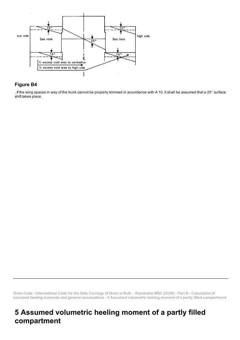
Figure B4. If the wing spaces in way of the trunk cannot be properly trimmed in accordance with A 10, it shall be assumed that a 25° surfaceshift takes place.
Grain Code International Code for the Safe Carriage of Grain in Bulk – Resolution MSC.23(59) Part B Calculation ofassumed heeling moments and general assumptions 5 Assumed volumetric heeling moment of a partly filled compartment
5 Assumed volumetric heeling moment of a partly filledcompartment
5.1. When the free surface of the bulk grain has not been secured in accordance with A 16, A 17 or A 18, it shall be assumed thatthe grain surface after shifting is at 25° to the horizontal.
5.2. In a partly filled compartment, a division, if fitted, shall extend from one eighth of the maximum breadth of the compartmentabove the level of the grain surface and to the same distance below the grain surface.
5.3. In a compartment in which the longitudinal divisions are not continuous between the transverse boundaries, the length overwhich any such divisions are effective as devices to prevent full width shifts of grain surfaces shall be taken to be the actual lengthof the portion of the division under consideration less two sevenths of the greater of the transverse distances between the divisionand its adjacent division or ship’s side. This correction does not apply in the lower compartments of any combination loading inwhich the upper compartment is either a filled compartment or a partly filled compartment.
Grain Code International Code for the Safe Carriage of Grain in Bulk – Resolution MSC.23(59) Part B Calculation ofassumed heeling moments and general assumptions 6 Other assumptions
6 Other assumptions. An Administration or a Contracting Government on behalf of an Administration may authorize departure from the assumptionscontained in this Code in those cases where it considers this to be justified having regard to the provisions for loading or structural
arrangements provided the stability criteria in A 7 are met. Where such authorization is granted under this regulation, particularsshall be included in the document of authorization or grain loading data.
Grain Code International Code for the Safe Carriage of Grain in Bulk – Resolution MSC.23(59) Appendix
Appendix. At its fiftyninth session, the Maritime Safety Committee adopted by resolution MSC.22(59) amendments to the 1974 SOLASConvention including a revised chapter VI. These amendments are contained in publication IMO168E.
. Part C of the revised chapter VI deals with the carriage of grain, and is supplemented by the present publication, the InternationalCode for the Safe Carriage of Grain in Bulk, adopted at the same session by resolution MSC.23(59).
. For ease of reference, part C of the revised chapter VI of the 1974 SOLAS Convention is reproduced below.
. Lloyd’s Register Note:
See SOLAS Chapter VI, Part C.
Footnote
FootnoteIt is recommended that loading conditions be provided for three representative stowage factors, e.g 1.25, 1.50, and 1.75 cubicmetres per tonne.


![Optimization of the beam crossing angle at the ILC for · arXiv:1801.10471v2 [physics.acc-ph] 27 Feb 2018 Prepared for submission to JINST Optimization of the beam crossing angle](https://static.fdocument.org/doc/165x107/5b14d1857f8b9a54488c4489/optimization-of-the-beam-crossing-angle-at-the-ilc-for-arxiv180110471v2-.jpg)