Giant Metrewave Radio Telescope (GMRT) - Introduction ...
58
Giant Metrewave Radio Telescope (GMRT) - Introduction, Current System & uGMRT Kaushal D. Buch Digital Backend Group, Giant Metrewave Radio Telescope [email protected]
Transcript of Giant Metrewave Radio Telescope (GMRT) - Introduction ...
Giant Metrewave Radio Telescope (GMRT) -
Introduction, Current System & uGMRT
Kaushal D. Buch
Digital Backend Group,
Giant Metrewave Radio Telescope [email protected]
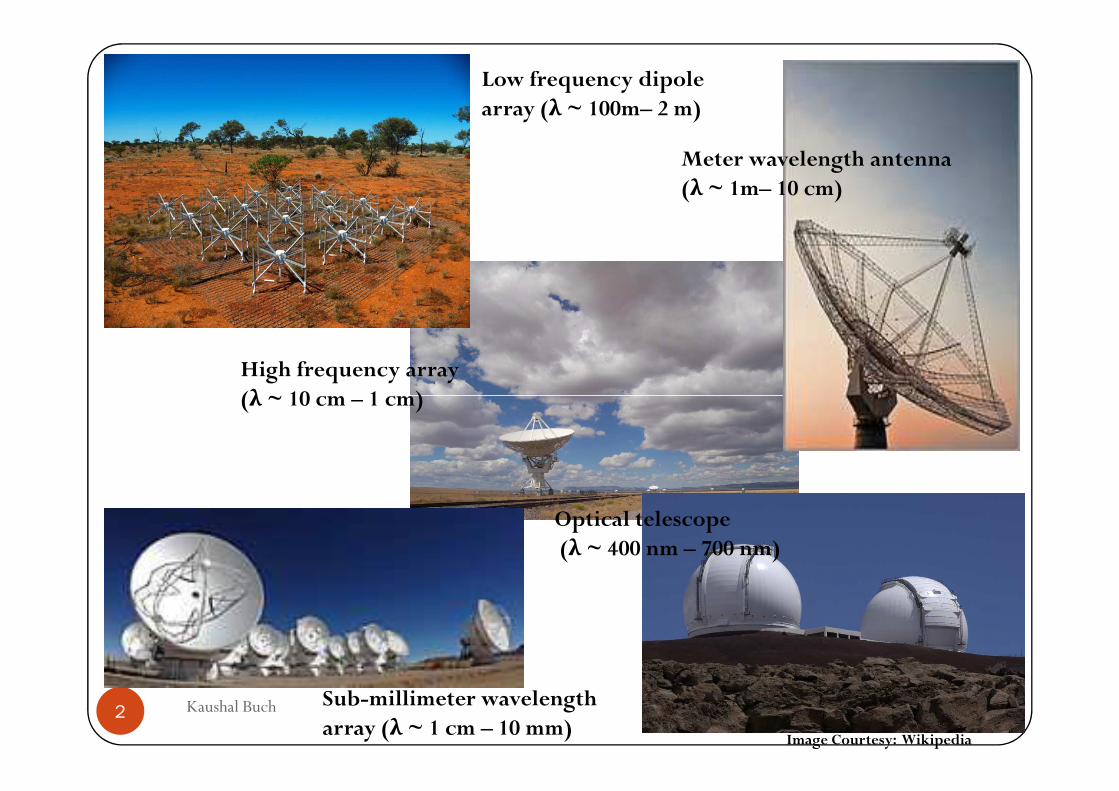
Low frequency dipole array (λ ~ 100m– 2 m)
High frequency array (λ ~ 10 cm – 1 cm)
Meter wavelength antenna (λ ~ 1m– 10 cm)
6/18/2015Kaushal Buch2
(λ ~ 10 cm – 1 cm)
Sub-millimeter wavelength array (λ ~ 1 cm – 10 mm)
Image Courtesy: Wikipedia
Optical telescope(λ ~ 400 nm – 700 nm)
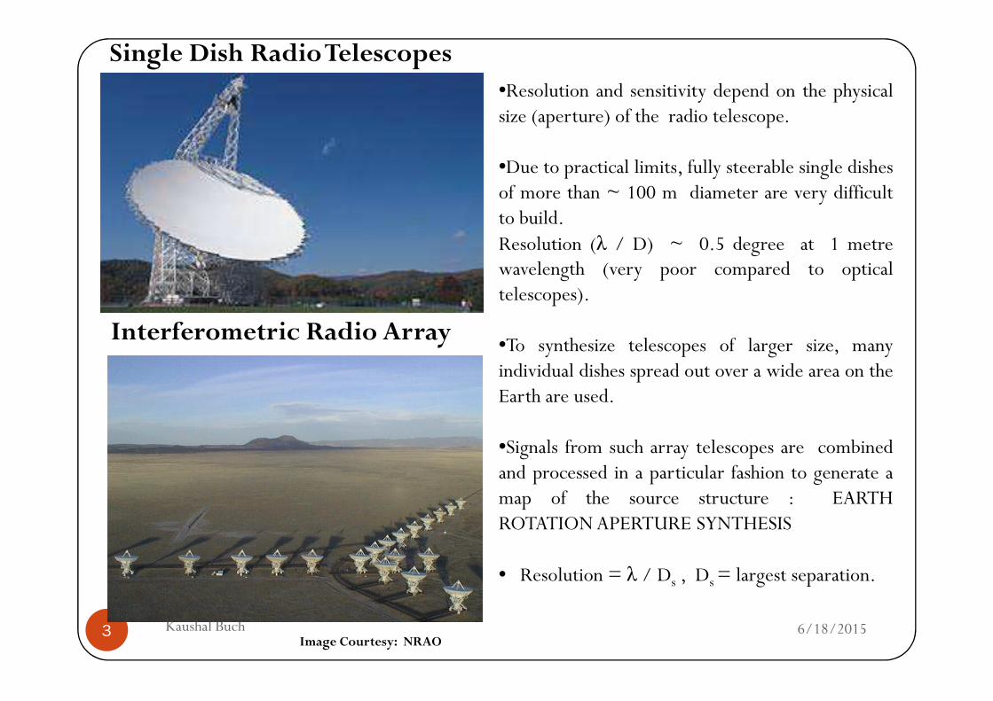
Single Dish Radio Telescopes
Interferometric Radio Array
•Resolution and sensitivity depend on the physicalsize (aperture) of the radio telescope.
•Due to practical limits, fully steerable single dishesof more than ~ 100 m diameter are very difficultto build.Resolution (λ / D) ~ 0.5 degree at 1 metrewavelength (very poor compared to opticaltelescopes).
•To synthesize telescopes of larger size, many
6/18/2015Kaushal Buch3
•To synthesize telescopes of larger size, manyindividual dishes spread out over a wide area on theEarth are used.
•Signals from such array telescopes are combinedand processed in a particular fashion to generate amap of the source structure : EARTHROTATION APERTURE SYNTHESIS
• Resolution = λ / Ds , Ds = largest separation.
Image Courtesy: NRAO
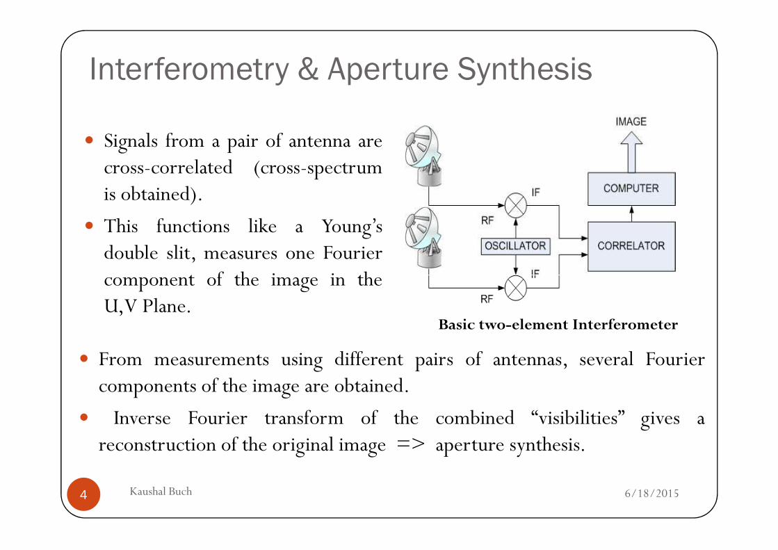
Interferometry & Aperture Synthesis
� Signals from a pair of antenna arecross-correlated (cross-spectrumis obtained).
� This functions like a Young’sdouble slit, measures one Fouriercomponent of the image in the
6/18/2015Kaushal Buch4
component of the image in theU,V Plane.
� From measurements using different pairs of antennas, several Fouriercomponents of the image are obtained.
� Inverse Fourier transform of the combined “visibilities” gives areconstruction of the original image => aperture synthesis.
Basic two-element Interferometer
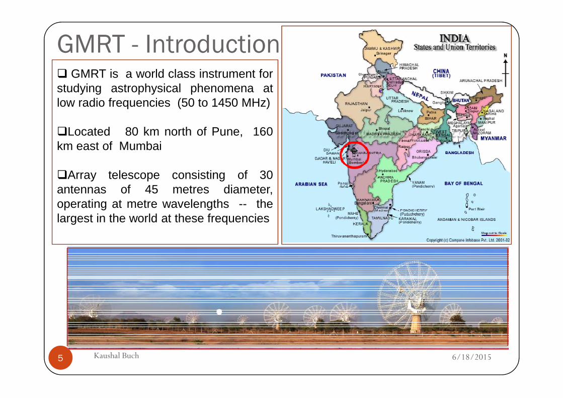
GMRT - Introduction� GMRT is a world class instrument forstudying astrophysical phenomena atlow radio frequencies (50 to 1450 MHz)
�Located 80 km north of Pune, 160km east of Mumbai
�Array telescope consisting of 30antennas of 45 metres diameter,operating at metre wavelengths -- the
6/18/20155 Kaushal Buch
operating at metre wavelengths -- thelargest in the world at these frequencies
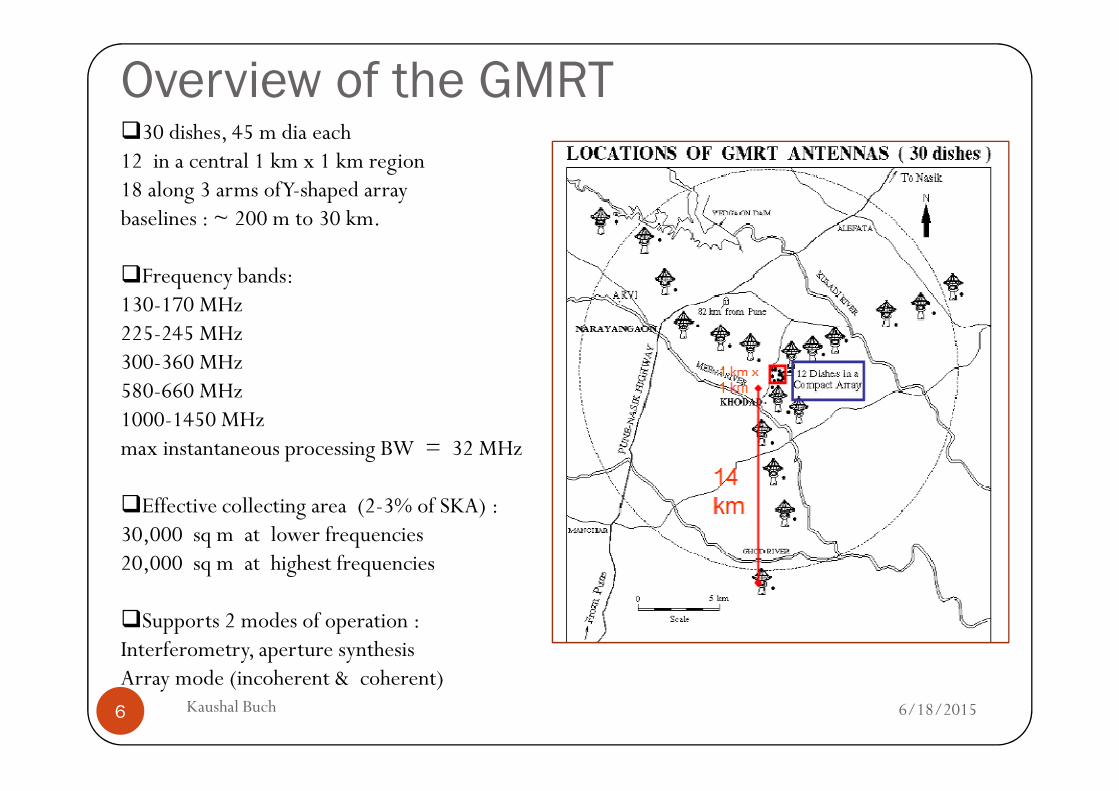
Overview of the GMRT�30 dishes, 45 m dia each 12 in a central 1 km x 1 km region 18 along 3 arms of Y-shaped array baselines : ~ 200 m to 30 km.
�Frequency bands: 130-170 MHz 225-245 MHz 300-360 MHz 580-660 MHz
6/18/20156 Kaushal Buch
580-660 MHz 1000-1450 MHz max instantaneous processing BW = 32 MHz
�Effective collecting area (2-3% of SKA) : 30,000 sq m at lower frequencies20,000 sq m at highest frequencies
�Supports 2 modes of operation :Interferometry, aperture synthesisArray mode (incoherent & coherent)
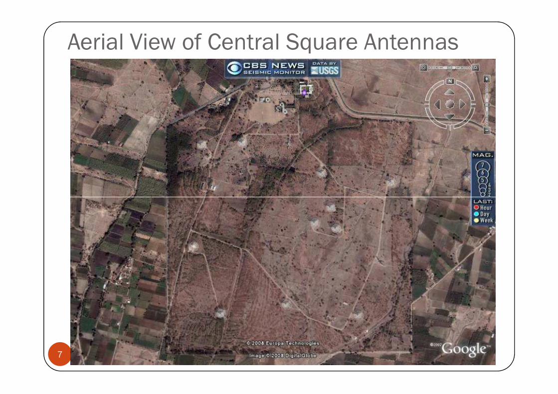
Aerial View of Central Square Antennas
6/18/2015Kaushal Buch7
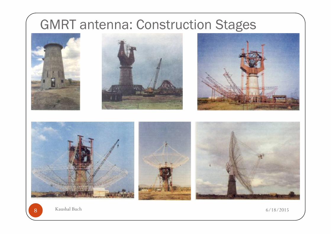
GMRT antenna: Construction Stages
6/18/2015Kaushal Buch8
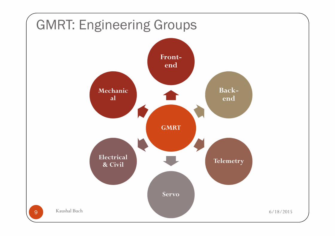
GMRT: Engineering Groups
Front-end
Back-end
Mechanical
6/18/2015Kaushal Buch9
GMRT
Telemetry
Servo
Electrical & Civil
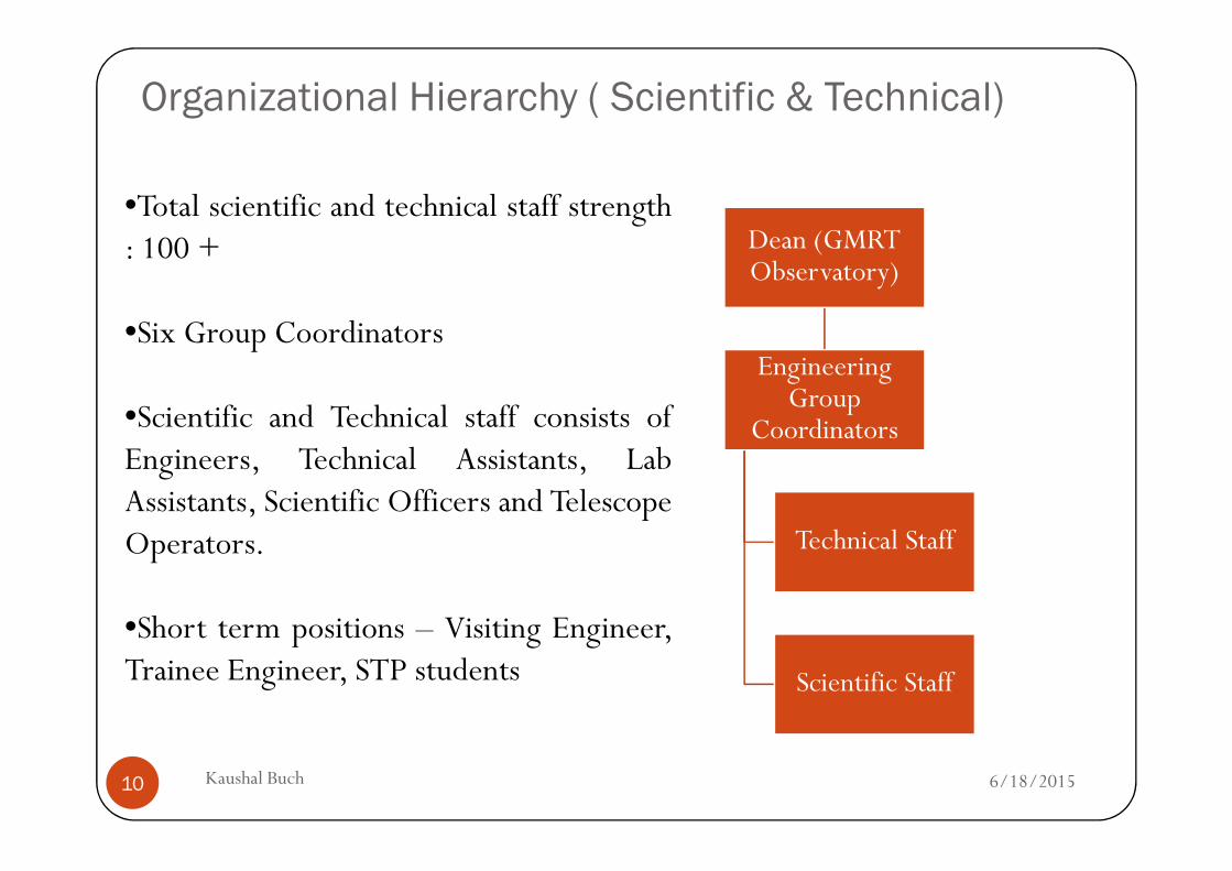
Organizational Hierarchy ( Scientific & Technical)
Dean (GMRT Observatory)
Engineering Group
Coordinators
•Total scientific and technical staff strength: 100 +
•Six Group Coordinators
•Scientific and Technical staff consists of
6/18/2015Kaushal Buch10
Coordinators
Technical Staff
Scientific Staff
Scientific and Technical staff consists ofEngineers, Technical Assistants, LabAssistants, Scientific Officers and TelescopeOperators.
•Short term positions – Visiting Engineer,Trainee Engineer, STP students
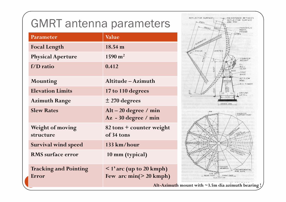
GMRT antenna parametersParameter Value
Focal Length 18.54 m
Physical Aperture 1590 m2
f/D ratio 0.412
Mounting Altitude – Azimuth
Elevation Limits 17 to 110 degrees
Azimuth Range ± 270 degrees
6/18/2015Kaushal Buch11
Azimuth Range ± 270 degrees
Slew Rates Alt – 20 degree / minAz - 30 degree / min
Weight of moving structure
82 tons + counter weight of 34 tons
Survival wind speed 133 km/hour
RMS surface error 10 mm (typical)
Tracking and Pointing Error
< 1’ arc (up to 20 kmph)Few arc min(> 20 kmph)
Alt-Azimuth mount with ~3.5m dia azimuth bearing !
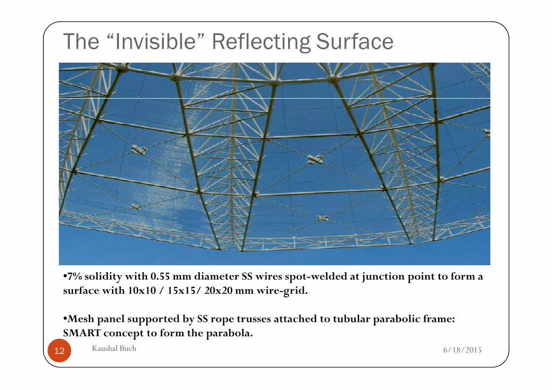
The “Invisible” Reflecting Surface
6/18/2015Kaushal Buch12
•7% solidity with 0.55 mm diameter SS wires spot-welded at junction point to form a surface with 10x10 / 15x15/ 20x20 mm wire-grid.
•Mesh panel supported by SS rope trusses attached to tubular parabolic frame: SMART concept to form the parabola.
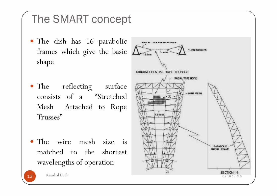
The SMART concept
� The dish has 16 parabolicframes which give the basicshape
� The reflecting surfaceconsists of a “Stretched
6/18/2015Kaushal Buch13
consists of a “StretchedMesh Attached to RopeTrusses”
� The wire mesh size ismatched to the shortestwavelengths of operation
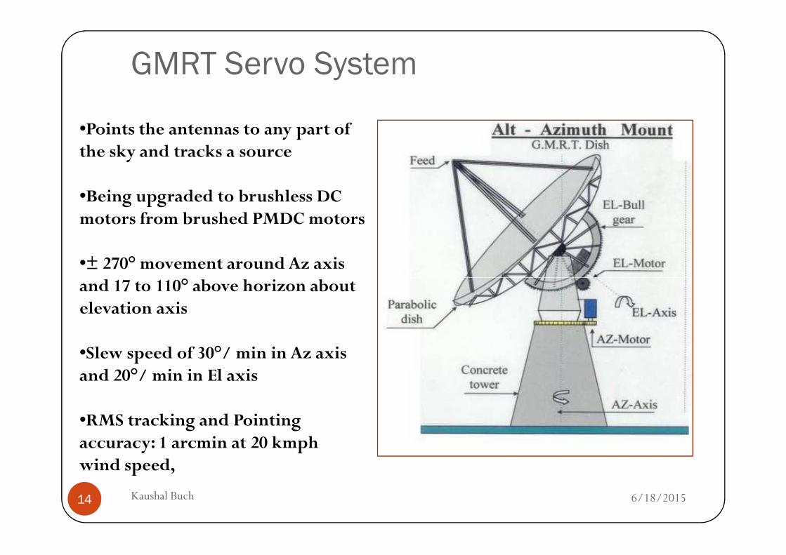
GMRT Servo System
•Points the antennas to any part of the sky and tracks a source
•Being upgraded to brushless DC motors from brushed PMDC motors
•± 270° movement around Az axis and 17 to 110° above horizon about
6/18/2015Kaushal Buch14
and 17 to 110° above horizon about elevation axis
•Slew speed of 30°/ min in Az axis and 20°/ min in El axis
•RMS tracking and Pointing accuracy: 1 arcmin at 20 kmphwind speed,
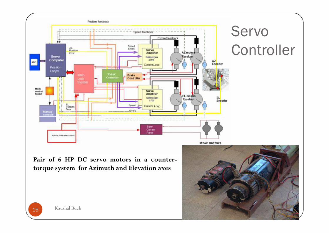
Servo
Controller
6/18/2015Kaushal Buch15
Pair of 6 HP DC servo motors in a counter-torque system for Azimuth and Elevation axes
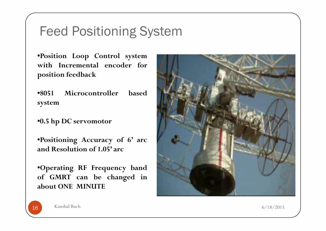
Feed Positioning System
•Position Loop Control systemwith Incremental encoder forposition feedback
•8051 Microcontroller basedsystem
6/18/2015Kaushal Buch16
•0.5 hp DC servomotor
•Positioning Accuracy of 6’ arcand Resolution of 1.05’ arc
•Operating RF Frequency bandof GMRT can be changed inabout ONE MINUTE
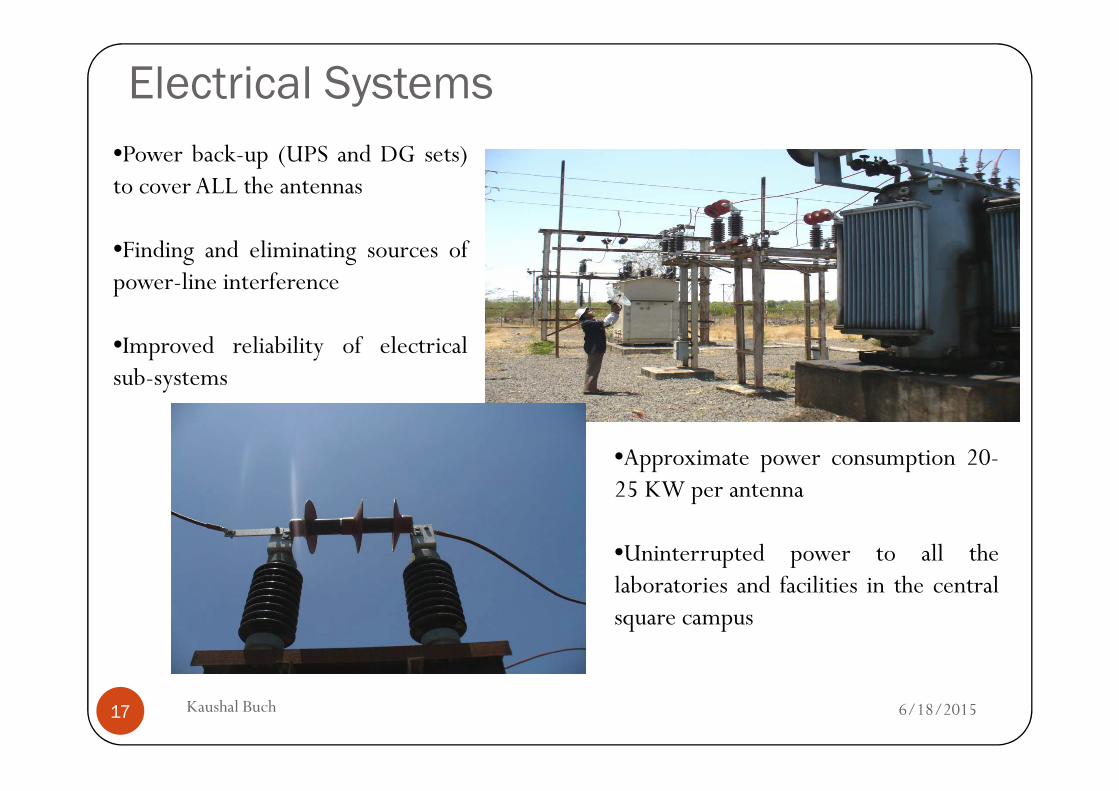
Electrical Systems
•Power back-up (UPS and DG sets)to cover ALL the antennas
•Finding and eliminating sources ofpower-line interference
•Improved reliability of electricalsub-systems
6/18/2015Kaushal Buch17
•Approximate power consumption 20-25 KW per antenna
•Uninterrupted power to all thelaboratories and facilities in the centralsquare campus
Radio Telescope Receiver
6/18/2015Kaushal Buch18
Radio Telescope Receiver
Radio Telescope Receiver Specifications� IDEAL Radio Telescope Receiver: INFINITE bandwidth and ZERO noise
� PRACTICAL Radio Telescope:
� Parabolic Reflector Surface acts like a Low-Pass Filter due to surface errors and reflector dimensions (~ 2 GHz for GMRT)
� Internationally protected frequency bands
� For Spectral line observations
� For Continuum Observations
� Celestial signals are very weak – measured in Jansky (Jy) (1 Jy = 10-26 Wm-2Hz-1 )
6/18/2015Kaushal Buch19
� Celestial signals are very weak – measured in Jansky (Jy) (1 Jy = 10-26 Wm-2Hz-1 )
� The input to the receiver (=kTB, ~ -100 dBm) must be amplified to around 0 dBm (=220 mv rms) for processing by the digital electronics.
Gain requirement of around 100 dB (1010 ) in the receiver chain
� The above gain must be distributed among various sub-systems with a good matching between
� Noise Figure
� Linear Dynamic Range
� Spurious Free Dynamic Range
� Ensure NO bottleneck is created by any Receiver stage !
Astronomical Signal Characteristics
6/18/2015Kaushal Buch20 -4 -3 -2 -1 0 1 2 3 40
100
200
300
400
500
600
700
800
900
1000
Value
Co
unt i
n B
in
Binned DataUnderlying Distribution
-4 -3 -2 -1 0 1 2 3 40
100
200
300
400
500
600
700
800
900
1000
Value
Co
unt i
n B
in
Binned DataUnderlying Distribution
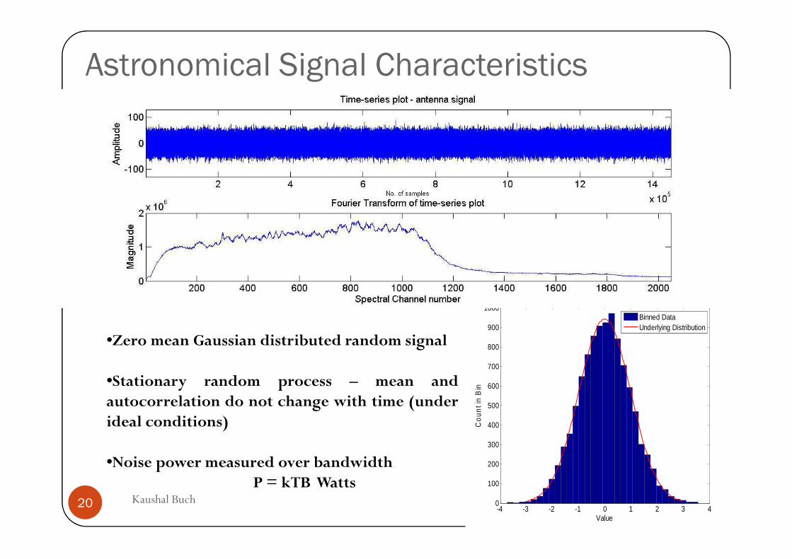
•Zero mean Gaussian distributed random signal
•Stationary random process – mean andautocorrelation do not change with time (underideal conditions)
•Noise power measured over bandwidthP = kTB Watts
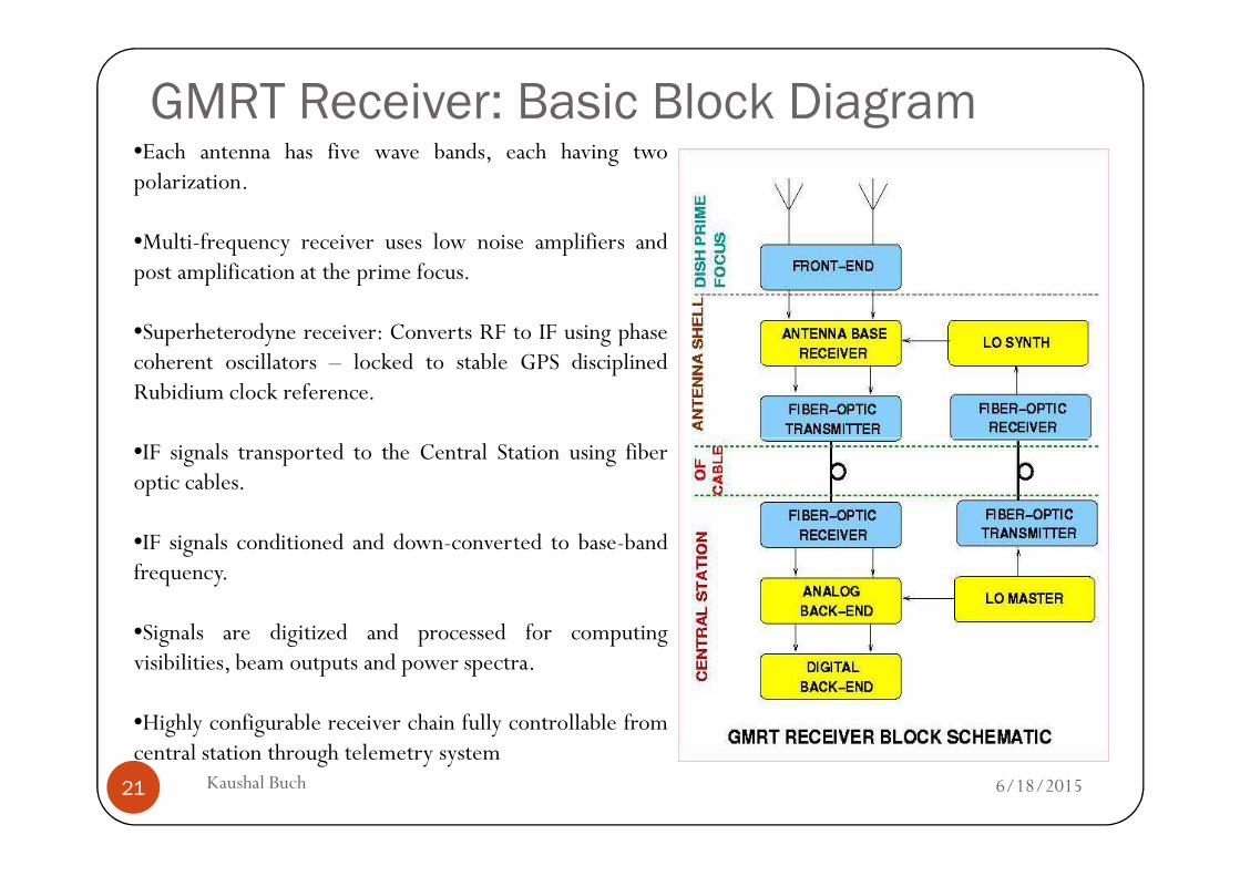
GMRT Receiver: Basic Block Diagram•Each antenna has five wave bands, each having twopolarization.
•Multi-frequency receiver uses low noise amplifiers andpost amplification at the prime focus.
•Superheterodyne receiver: Converts RF to IF using phasecoherent oscillators – locked to stable GPS disciplinedRubidium clock reference.
•
6/18/2015Kaushal Buch21
•IF signals transported to the Central Station using fiberoptic cables.
•IF signals conditioned and down-converted to base-bandfrequency.
•Signals are digitized and processed for computingvisibilities, beam outputs and power spectra.
•Highly configurable receiver chain fully controllable fromcentral station through telemetry system
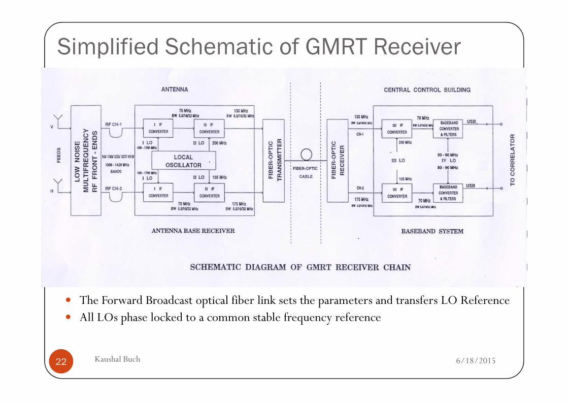
Simplified Schematic of GMRT Receiver
6/18/2015Kaushal Buch22
� The Forward Broadcast optical fiber link sets the parameters and transfers LO Reference� All LOs phase locked to a common stable frequency reference
Feeds of the GMRT
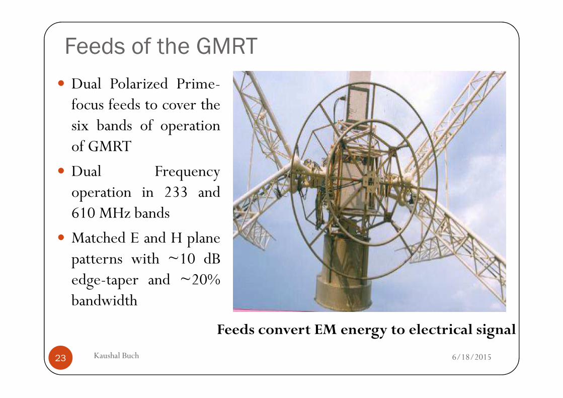
� Dual Polarized Prime-focus feeds to cover thesix bands of operationof GMRT
� Dual Frequencyoperation in 233 and
6/18/2015Kaushal Buch23
operation in 233 and610 MHz bands
� Matched E and H planepatterns with ~10 dBedge-taper and ~20%bandwidth
Feeds convert EM energy to electrical signal
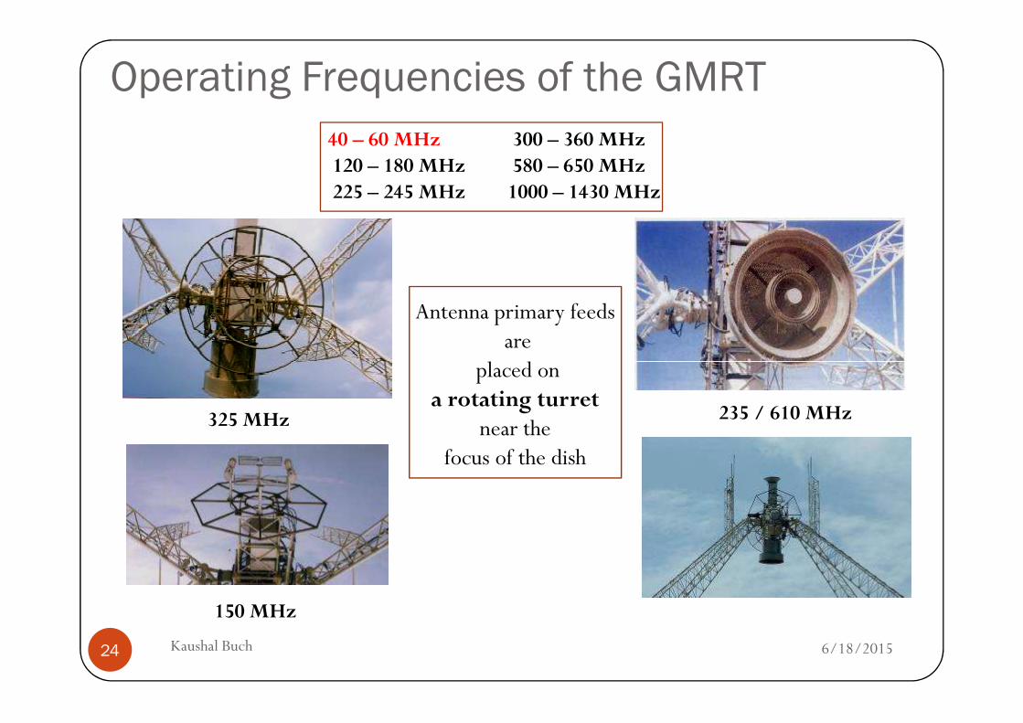
Operating Frequencies of the GMRT
40 – 60 MHz 300 – 360 MHz120 – 180 MHz 580 – 650 MHz225 – 245 MHz 1000 – 1430 MHz
Antenna primary feedsare
placed on
6/18/2015Kaushal Buch24
placed on a rotating turret
near the focus of the dish
325 MHz
150 MHz
235 / 610 MHz
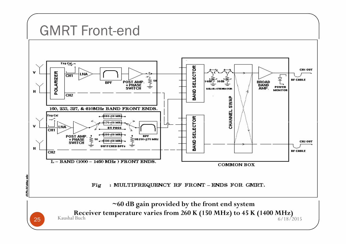
GMRT Front-end
6/18/2015Kaushal Buch25
~60 dB gain provided by the front end system Receiver temperature varies from 260 K (150 MHz) to 45 K (1400 MHz)
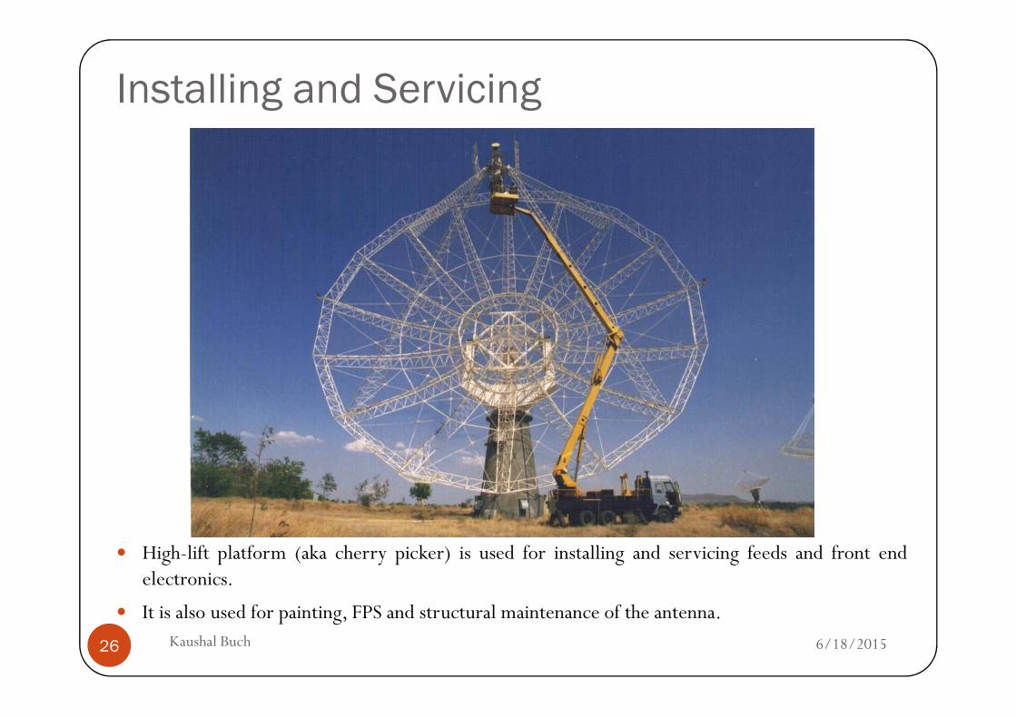
Installing and Servicing
6/18/2015Kaushal Buch26
� High-lift platform (aka cherry picker) is used for installing and servicing feeds and front endelectronics.
� It is also used for painting, FPS and structural maintenance of the antenna.
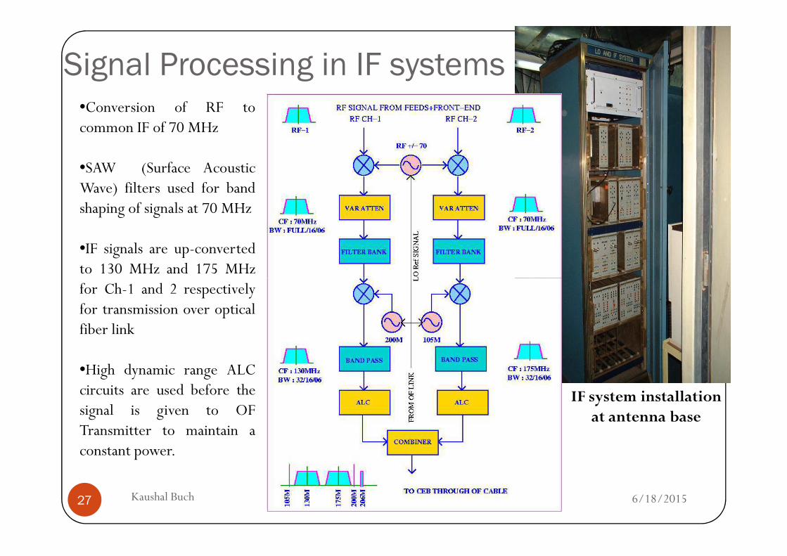
Signal Processing in IF systems•Conversion of RF tocommon IF of 70 MHz
•SAW (Surface AcousticWave) filters used for bandshaping of signals at 70 MHz
•IF signals are up-convertedto 130 MHz and 175 MHz
6/18/2015Kaushal Buch27
to 130 MHz and 175 MHzfor Ch-1 and 2 respectivelyfor transmission over opticalfiber link
•High dynamic range ALCcircuits are used before thesignal is given to OFTransmitter to maintain aconstant power.
IF system installation at antenna base
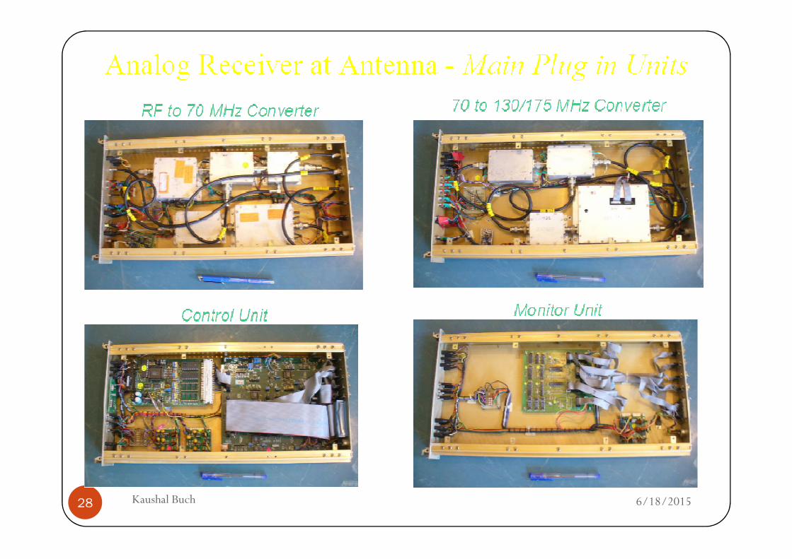
6/18/2015Kaushal Buch28
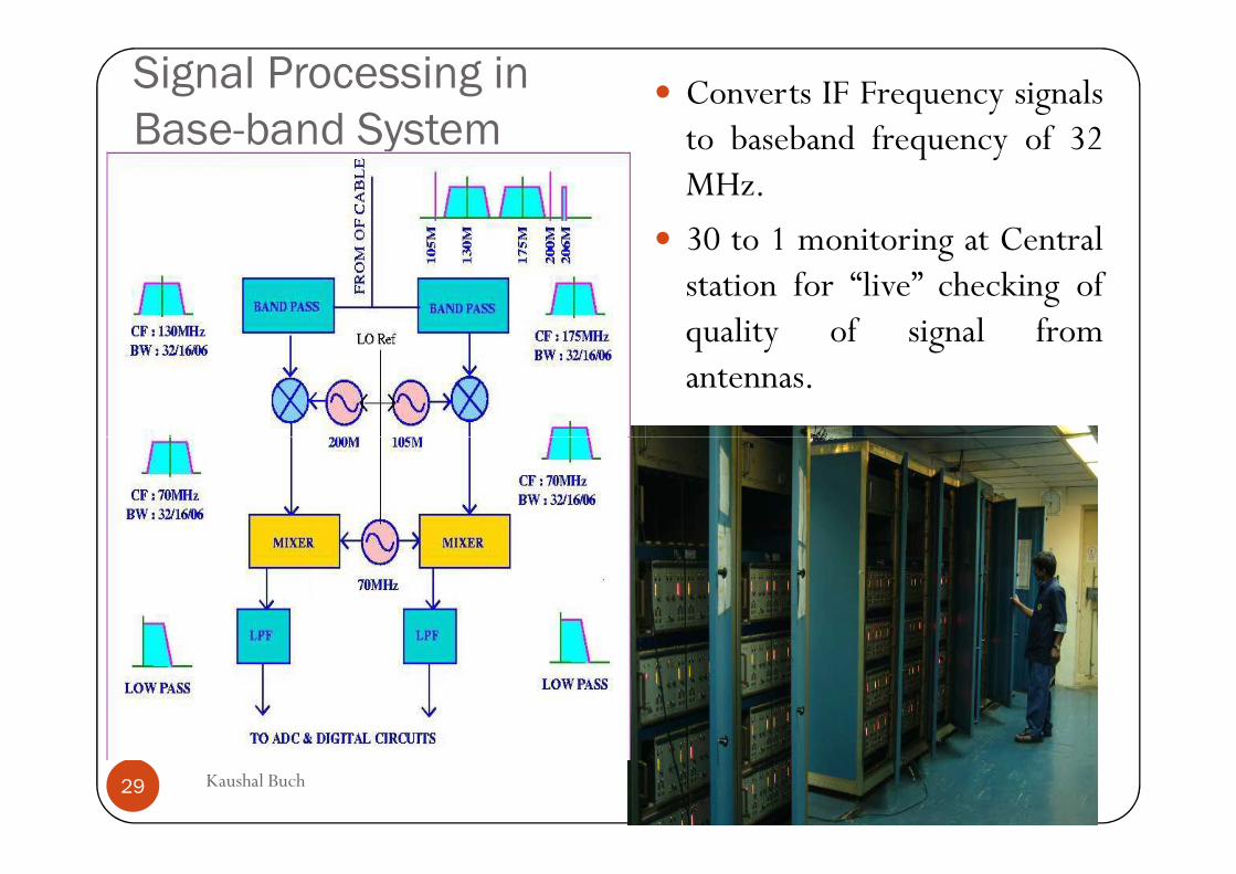
Signal Processing in
Base-band System� Converts IF Frequency signals
to baseband frequency of 32MHz.
� 30 to 1 monitoring at Centralstation for “live” checking ofquality of signal fromantennas.
6/18/2015Kaushal Buch29
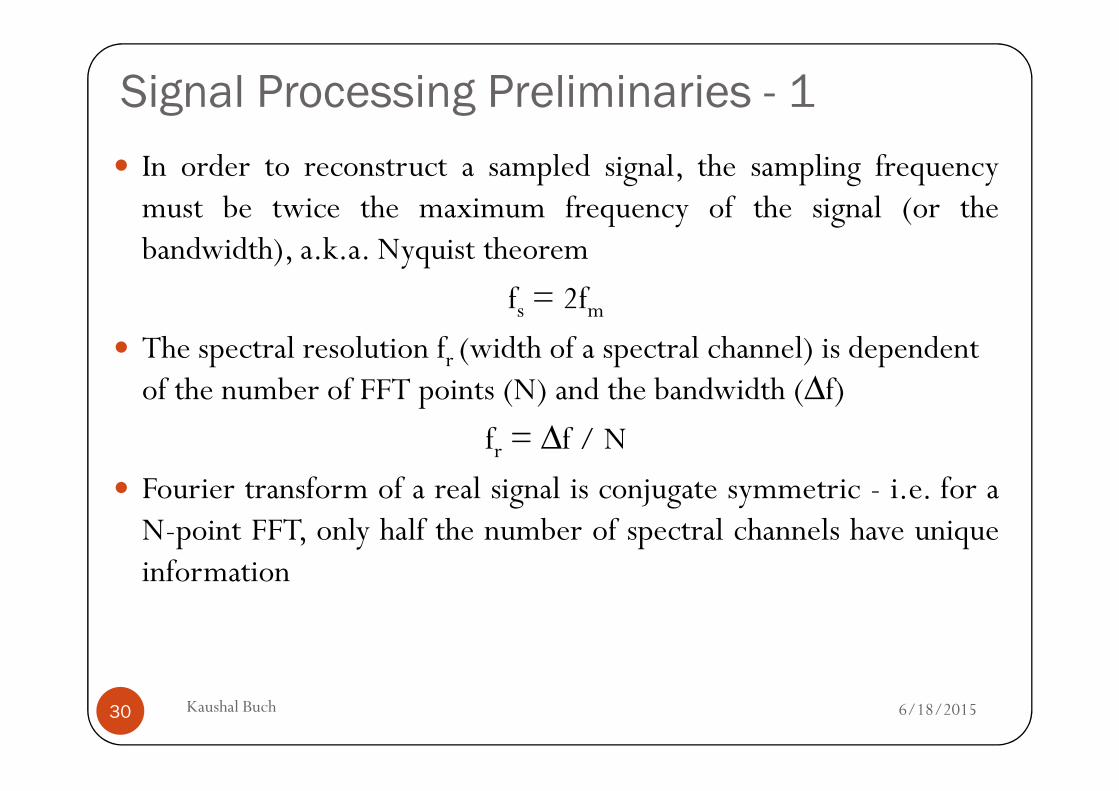
Signal Processing Preliminaries - 1
� In order to reconstruct a sampled signal, the sampling frequencymust be twice the maximum frequency of the signal (or thebandwidth), a.k.a. Nyquist theorem
fs = 2fm
� The spectral resolution fr (width of a spectral channel) is dependent of the number of FFT points (N) and the bandwidth (∆f)
6/18/2015Kaushal Buch30
of the number of FFT points (N) and the bandwidth (∆f)
fr = ∆f / N
� Fourier transform of a real signal is conjugate symmetric - i.e. for aN-point FFT, only half the number of spectral channels have uniqueinformation
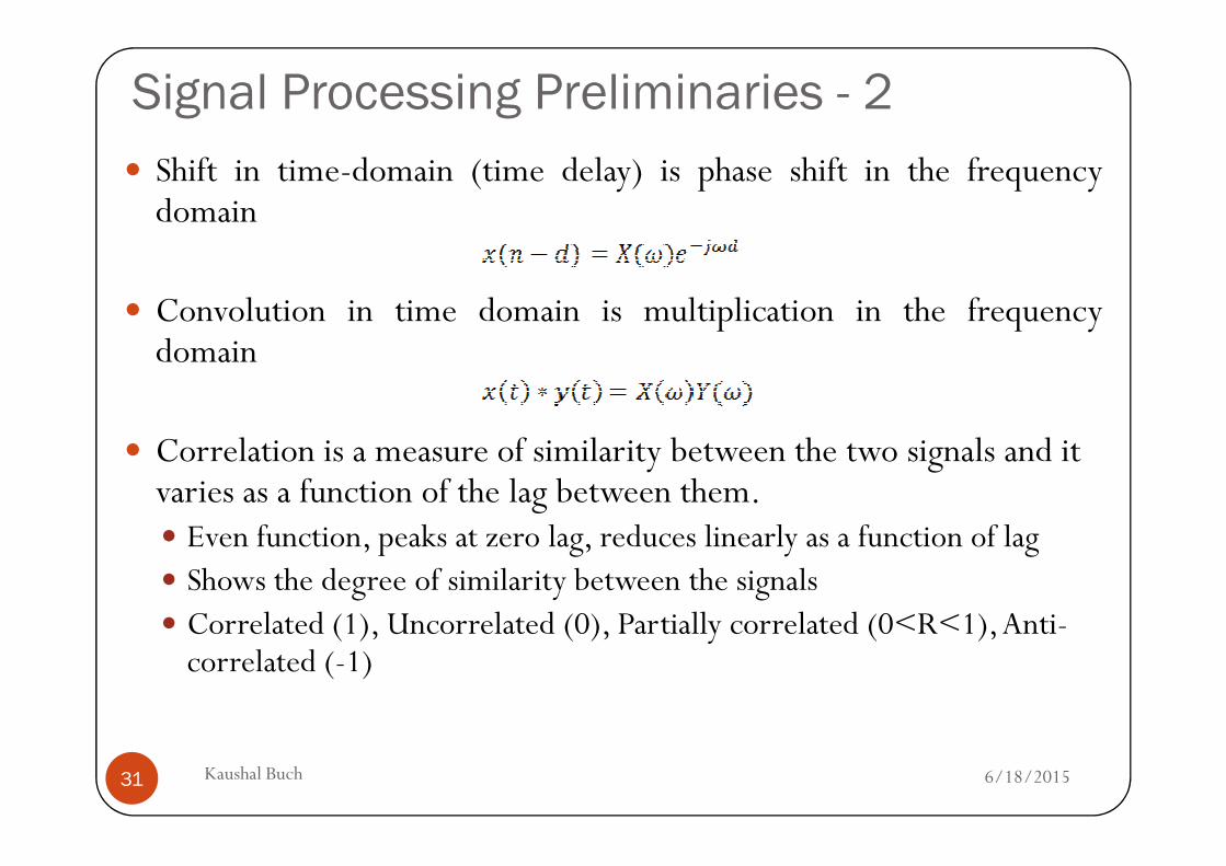
Signal Processing Preliminaries - 2
� Shift in time-domain (time delay) is phase shift in the frequencydomain
� Convolution in time domain is multiplication in the frequencydomain
Correlation is a measure of similarity between the two signals and it
6/18/2015Kaushal Buch31
� Correlation is a measure of similarity between the two signals and it varies as a function of the lag between them.� Even function, peaks at zero lag, reduces linearly as a function of lag� Shows the degree of similarity between the signals� Correlated (1), Uncorrelated (0), Partially correlated (0<R<1), Anti-
correlated (-1)
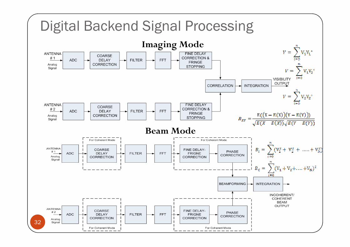
Digital Backend Signal ProcessingImaging Mode
32
Beam Mode
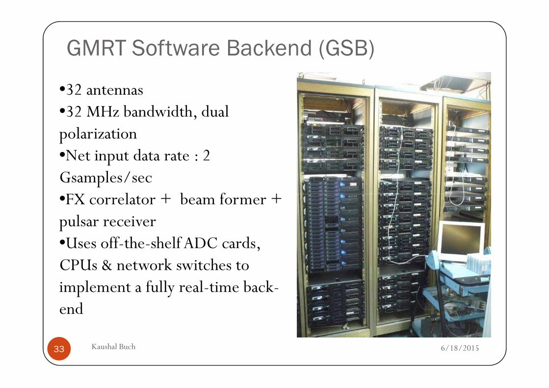
GMRT Software Backend (GSB)
•32 antennas•32 MHz bandwidth, dual polarization•Net input data rate : 2 Gsamples/sec •FX correlator + beam former +
6/18/2015Kaushal Buch33
•FX correlator + beam former + pulsar receiver•Uses off-the-shelf ADC cards, CPUs & network switches to implement a fully real-time back-end
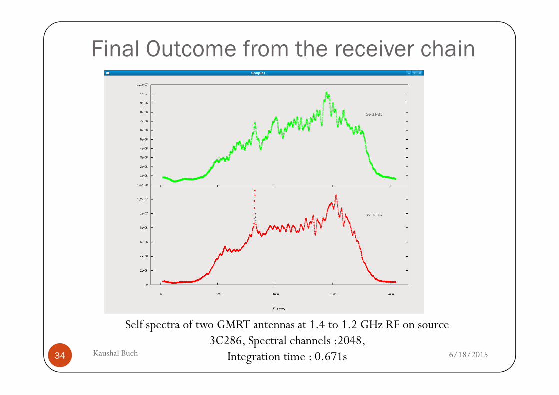
Final Outcome from the receiver chain
6/18/2015Kaushal Buch34
Self spectra of two GMRT antennas at 1.4 to 1.2 GHz RF on source 3C286, Spectral channels :2048,
Integration time : 0.671s
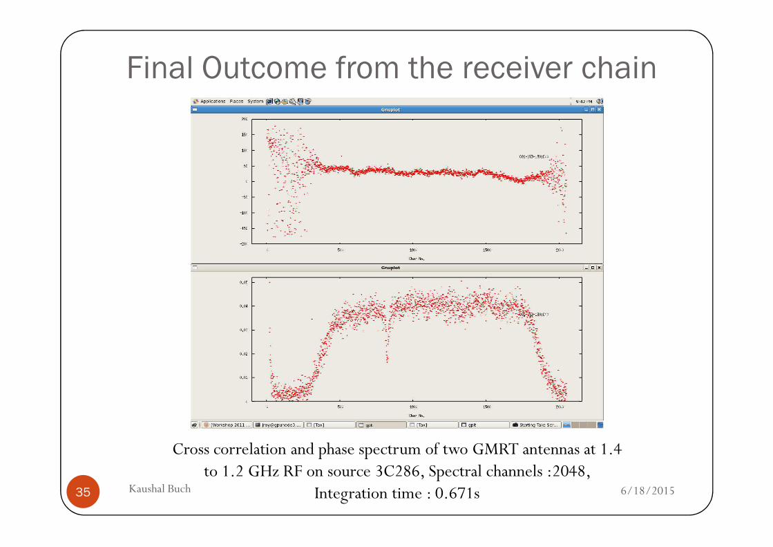
Final Outcome from the receiver chain
6/18/2015Kaushal Buch35
Cross correlation and phase spectrum of two GMRT antennas at 1.4 to 1.2 GHz RF on source 3C286, Spectral channels :2048,
Integration time : 0.671s

The uGMRT
6/18/2015Kaushal Buch36
The uGMRT
The Upgraded GMRT (uGMRT)
A major upgrade is underway now at the GMRT with focus on:• Seamless frequency coverage from ~30 MHz to 1500 MHz -> design
of new feeds and receiver system• Improved G/Tsys by reduced system temperature -> better
technology receivers• Increased instantaneous bandwidth of 400 MHz (from the present
maximum of 32 MHz) -> modern new digital back-end
6/18/2015Kaushal Buch37
maximum of 32 MHz) -> modern new digital back-endreceiver
• Revamped servo system for the antennas• Modern and versatile control and monitoring system• Matching improvements in offline computing facilities and
other infrastructure• Improvements in mechanical systems and infrastructure
facilities
Features : Comparison with Current System
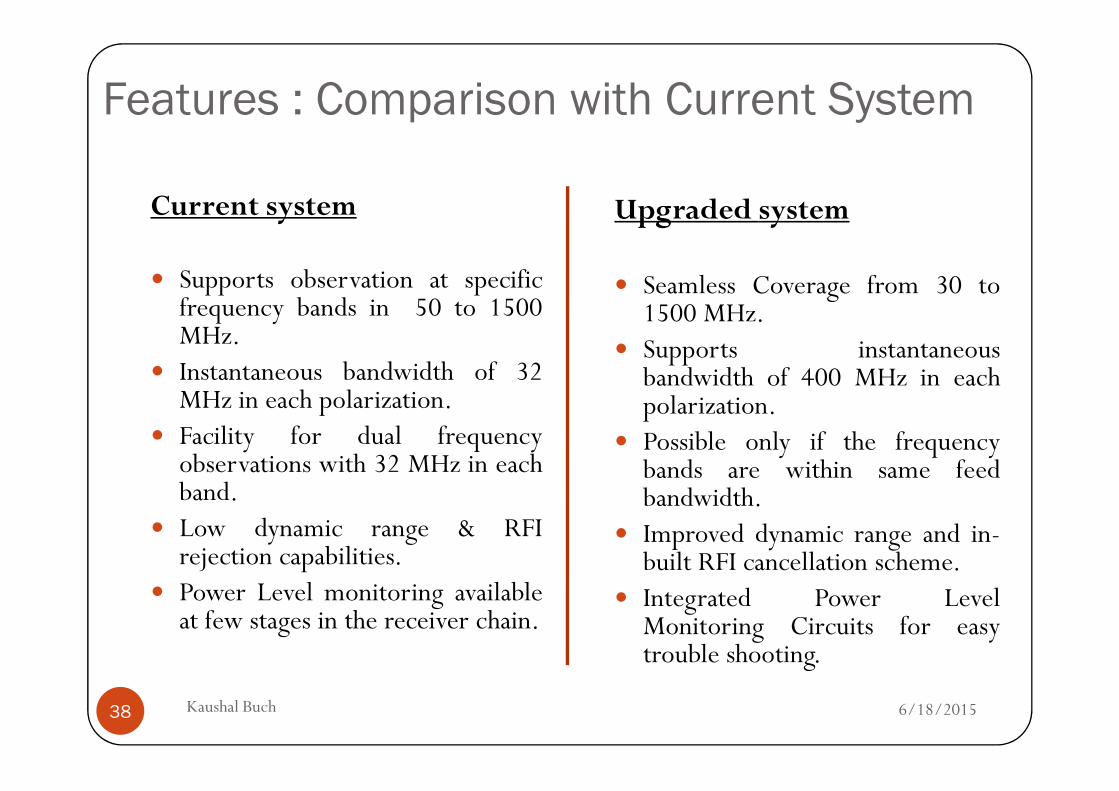
Current system
� Supports observation at specificfrequency bands in 50 to 1500MHz.
� Instantaneous bandwidth of 32MHz in each polarization.
Upgraded system
� Seamless Coverage from 30 to1500 MHz.
� Supports instantaneousbandwidth of 400 MHz in eachpolarization.
6/18/2015Kaushal Buch38
MHz in each polarization.� Facility for dual frequency
observations with 32 MHz in eachband.
� Low dynamic range & RFIrejection capabilities.
� Power Level monitoring availableat few stages in the receiver chain.
polarization.� Possible only if the frequency
bands are within same feedbandwidth.
� Improved dynamic range and in-built RFI cancellation scheme.
� Integrated Power LevelMonitoring Circuits for easytrouble shooting.
Benefits of
uGMRT
6/18/2015Kaushal Buch39
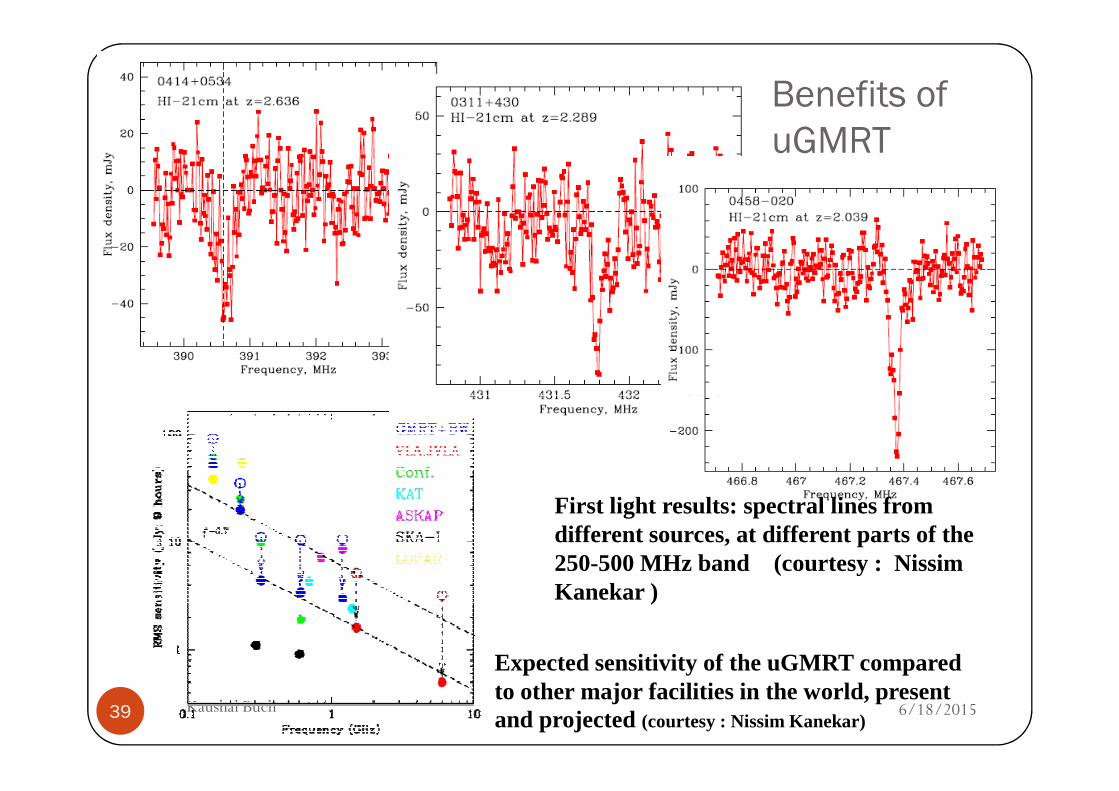
First light results: spectral lines from different sources, at different parts of the 250-500 MHz band (courtesy : NissimKanekar )
Expected sensitivity of the uGMRT compared to other major facilities in the world, present and projected (courtesy : Nissim Kanekar)
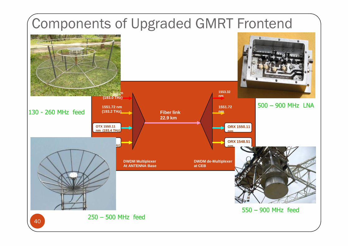
1551.72 nm (193.2 THz)
1553.32 nm(193.0 THz)
1551.72 nm
1553.32 nm
Fiber link 22.9 km
Components of Upgraded GMRT Frontend
500 500 –– 900 MHz LNA900 MHz LNA
130 130 -- 260 260 MHz feedMHz feed
OTX 1550.11 nm (193.4 THz)
OTX 1548.51 nm (193.6 THz)
ORX 1550.11 nm
ORX 1548.51 nm
DWDM Multiplexer At ANTENNA Base
DWDM de-Multiplexer at CEB
40 CASPER Meet 2013 Kaushal Buch
550 550 –– 900 MHz feed900 MHz feed
250 250 –– 500 MHz feed500 MHz feed
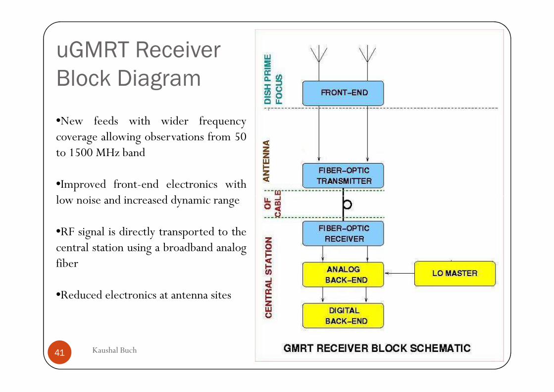
uGMRT Receiver
Block Diagram
•New feeds with wider frequencycoverage allowing observations from 50to 1500 MHz band
•Improved front-end electronics withlow noise and increased dynamic range
6/18/2015Kaushal Buch41
low noise and increased dynamic range
•RF signal is directly transported to thecentral station using a broadband analogfiber
•Reduced electronics at antenna sites
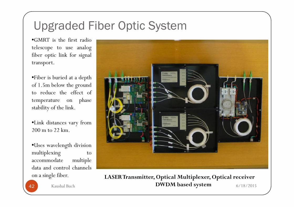
Upgraded Fiber Optic System•GMRT is the first radiotelescope to use analogfiber optic link for signaltransport.
•Fiber is buried at a depthof 1.5m below the groundto reduce the effect oftemperature on phase
6/18/2015Kaushal Buch42
LASER Transmitter, Optical Multiplexer, Optical receiverDWDM based system
temperature on phasestability of the link.
•Link distances vary from200 m to 22 km.
•Uses wavelength divisionmultiplexing toaccommodate multipledata and control channelson a single fiber.
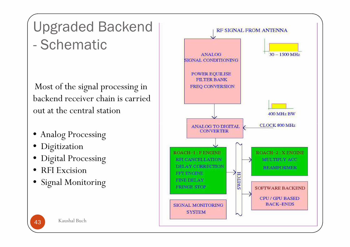
Upgraded Backend
- Schematic
Most of the signal processing in backend receiver chain is carried out at the central station
6/18/2015Kaushal Buch43
• Analog Processing • Digitization• Digital Processing• RFI Excision• Signal Monitoring
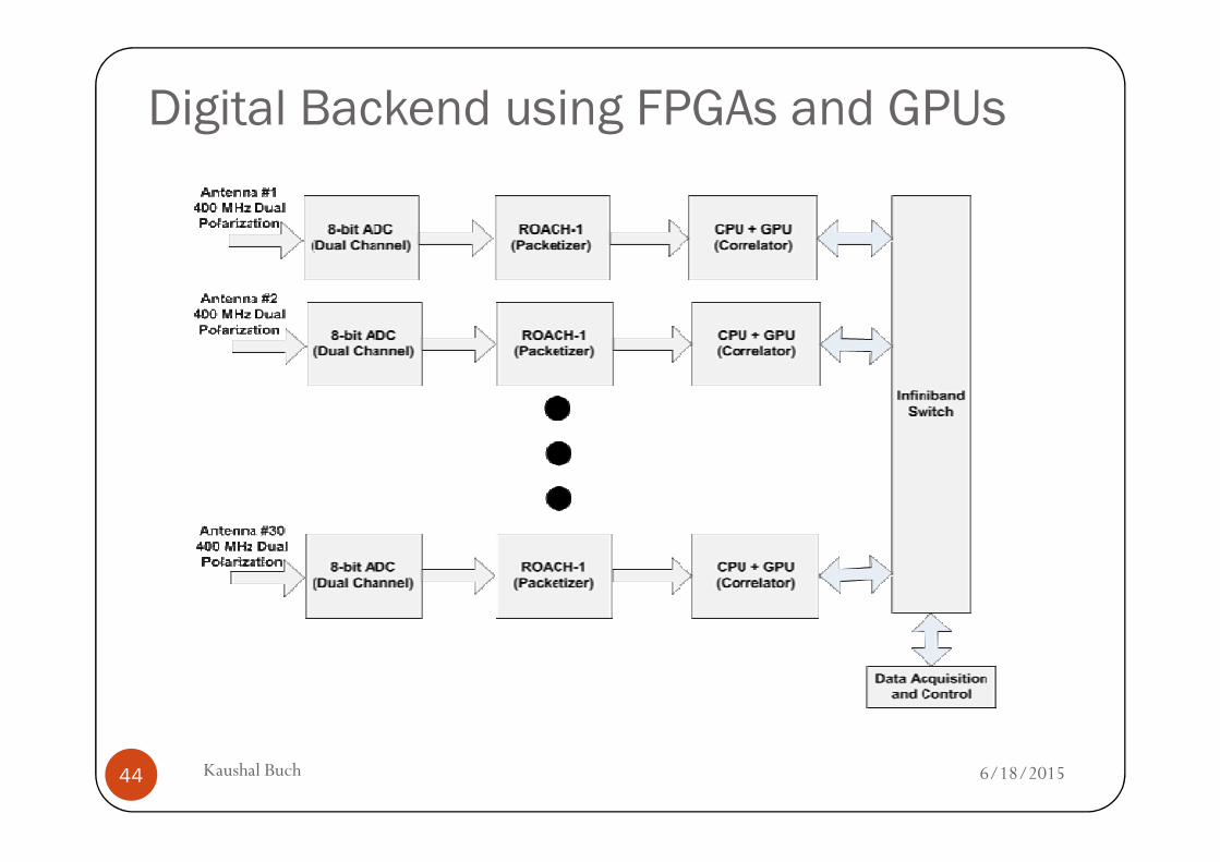
Digital Backend using FPGAs and GPUs
6/18/2015Kaushal Buch44
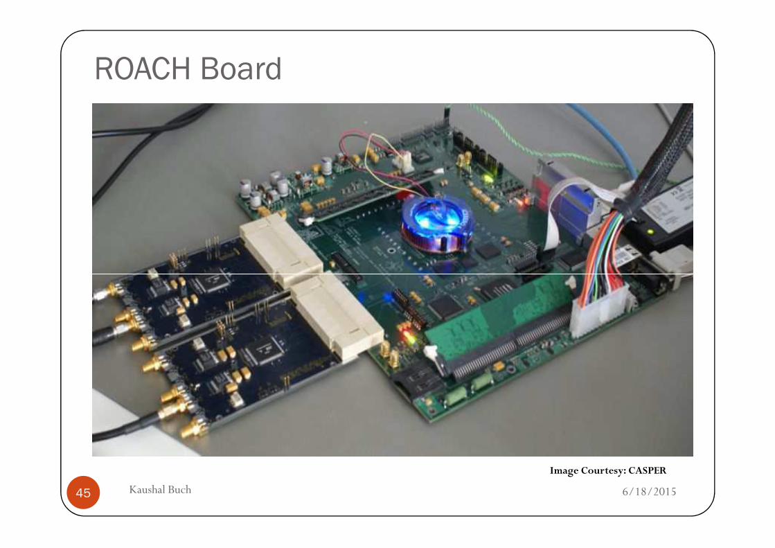
ROACH Board
6/18/2015Kaushal Buch45
Image Courtesy: CASPER
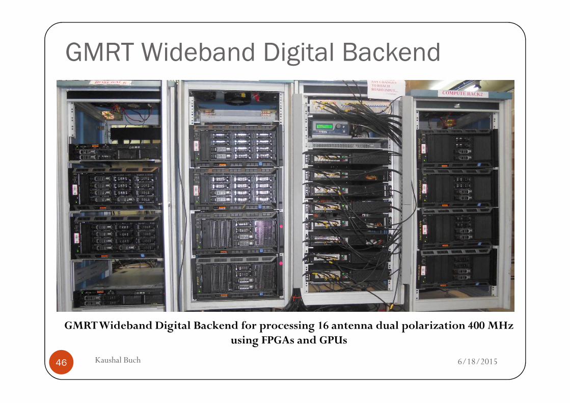
GMRT Wideband Digital Backend
6/18/2015Kaushal Buch46
GMRT Wideband Digital Backend for processing 16 antenna dual polarization 400 MHz using FPGAs and GPUs
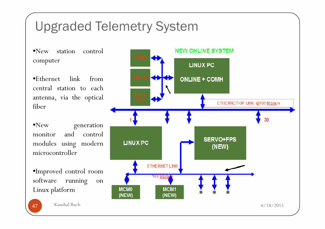
Upgraded Telemetry System
•New station controlcomputer
•Ethernet link fromcentral station to eachantenna, via the opticalfiber
6/18/2015Kaushal Buch47
•New generationmonitor and controlmodules using modernmicrocontroller
•Improved control roomsoftware running onLinux platform
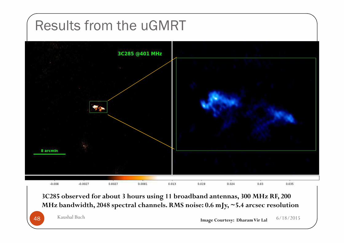
Results from the uGMRT
6/18/2015Kaushal Buch48
3C285 observed for about 3 hours using 11 broadband antennas, 300 MHz RF, 200 MHz bandwidth, 2048 spectral channels. RMS noise: 0.6 mJy, ~5.4 arcsec resolution
Image Courtesy: DharamVir Lal
Challenges for Radio Telescopes
6/18/2015Kaushal Buch49
Challenges for Radio Telescopes
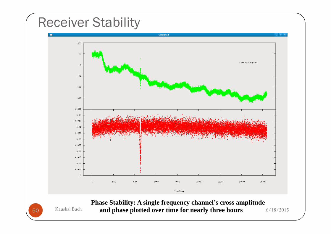
Receiver Stability
6/18/2015Kaushal Buch50
Phase Stability: A single frequency channel’s cross amplitude and phase plotted over time for nearly three hours
Radio Frequency Interference
� Man-made electromagnetic radiation fromelectronic/electrical equipments
� RFI is typically 30 to 40 dB (i.e. 1000 to 10000 times)stronger than astronomical signalstronger than astronomical signal
� RFI has a non-random distribution
� RFI mitigation – very important problem (challenge)for contemporary radio telescopes
6/18/201551 Kaushal Buch
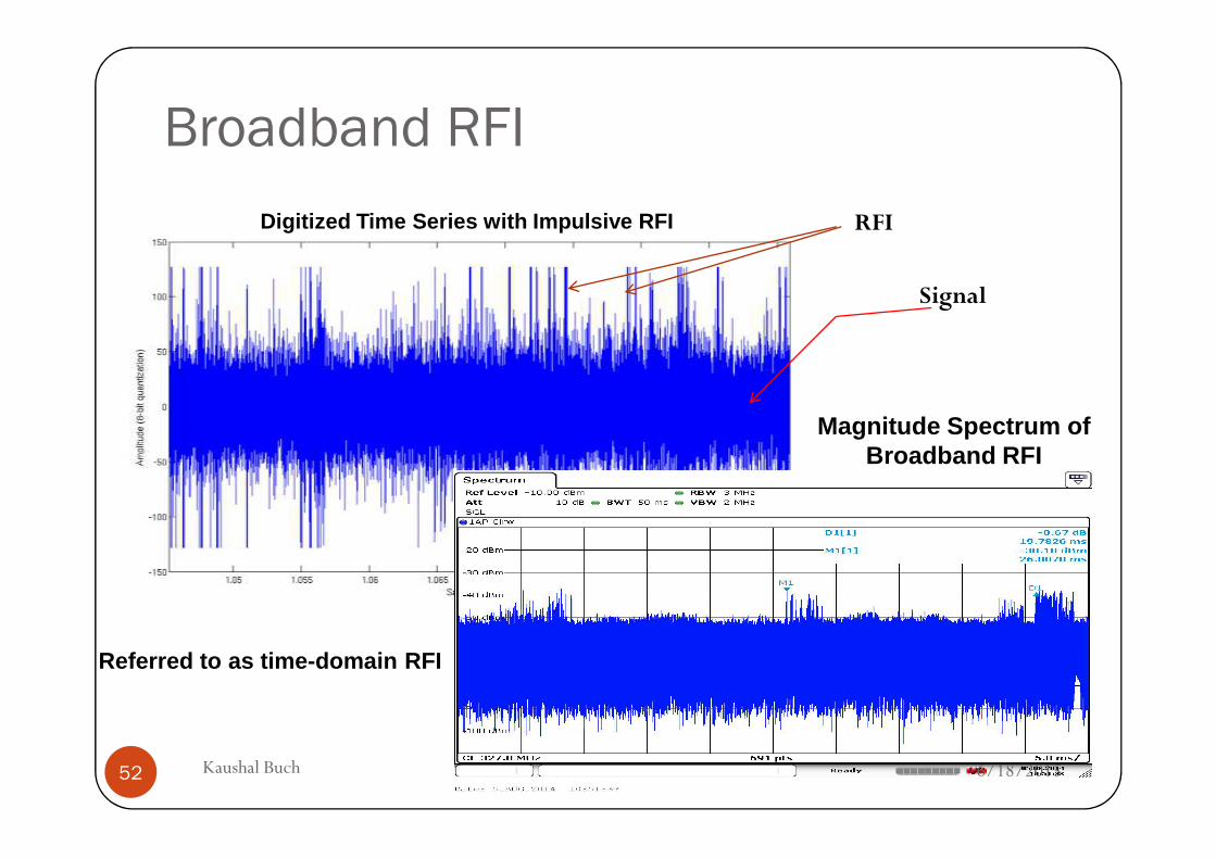
Broadband RFI
Digitized Time Series with Impulsive RFI
Signal
RFI
Magnitude Spectrum of Magnitude Spectrum of Broadband RFI
6/18/201552 Kaushal Buch
Referred to as time-domain RFI
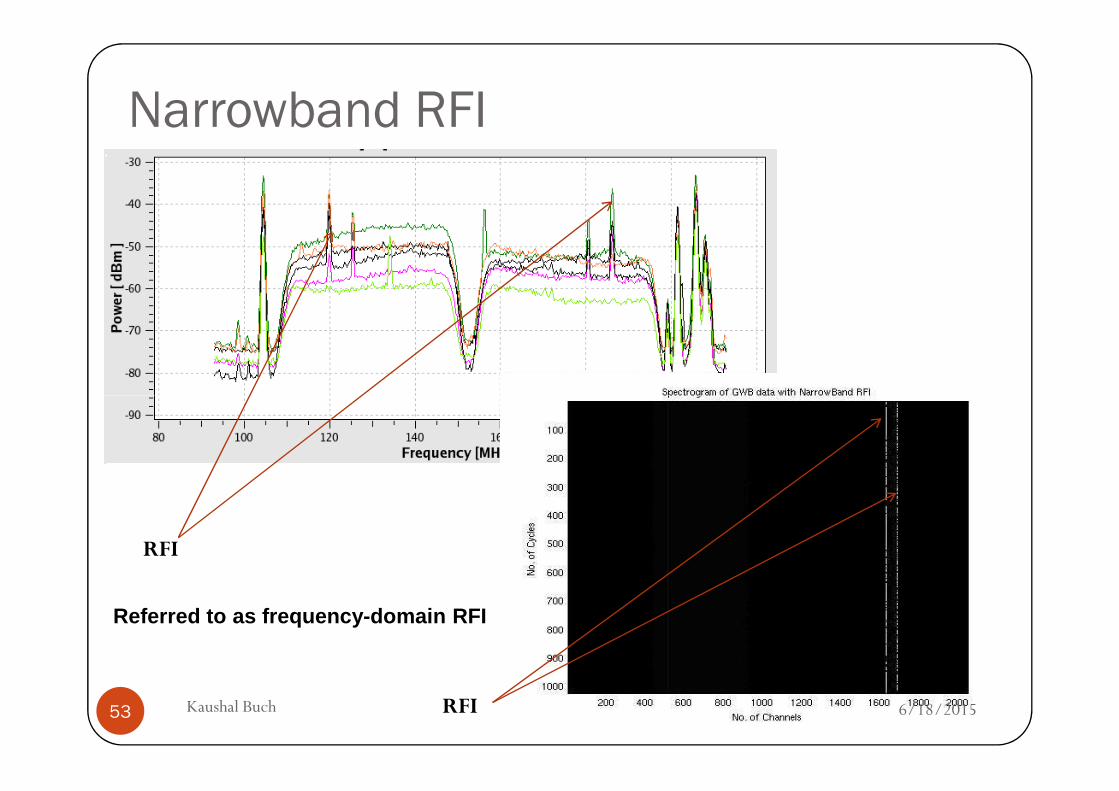
Narrowband RFI
RFI
RFI 6/18/201553 Kaushal Buch
Referred to as frequency-domain RFI
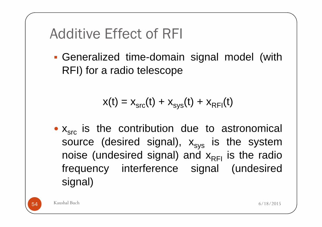
Additive Effect of RFI
� Generalized time-domain signal model (withRFI) for a radio telescope
x(t) = xsrc(t) + xsys(t) + xRFI(t)
6/18/2015Kaushal Buch54
� xsrc is the contribution due to astronomicalsource (desired signal), xsys is the systemnoise (undesired signal) and xRFI is the radiofrequency interference signal (undesiredsignal)
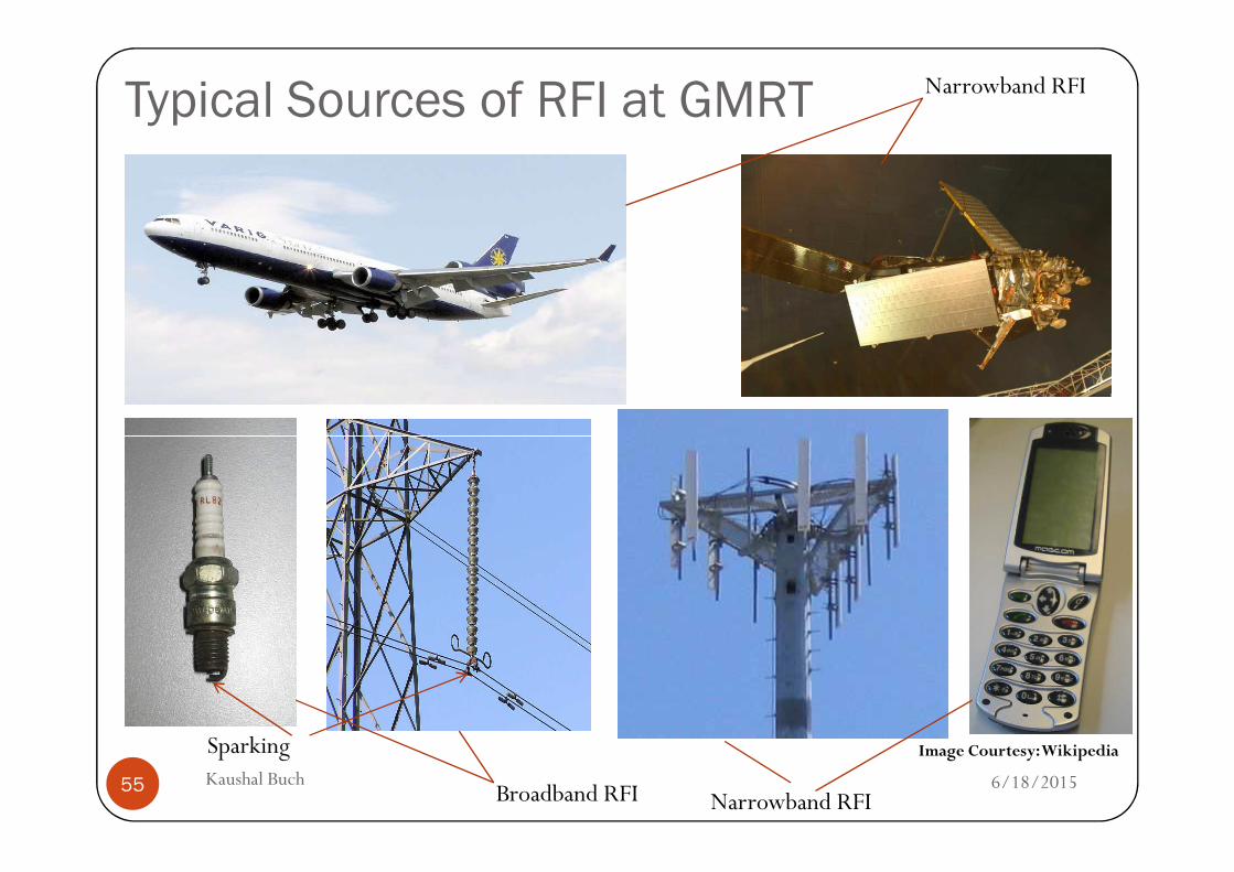
Typical Sources of RFI at GMRT Narrowband RFI
6/18/2015Kaushal Buch55
Image Courtesy: WikipediaSparking
Broadband RFI Narrowband RFI
Effects of RFI
� Presence of RFI� Signal fluctuations do not integrate down as t-0.5 upon
temporal averaging� Leads to reduced signal to noise ratio (SNR) and sensitivity
� Strong narrowband RFI lines
6/18/2015Kaushal Buch56
� Produces harmonics� Pronounced effects due to spectral leakage
o Increased side-lobe levelso Reduced dynamic range
� Limits detection and analyses of weak radiosources, temporal events and transients
AcknowledgementsI would like to thank the following colleagues at GMRT & NCRA
for their help in this presentation and related technical discussions
Yashwant Gupta
Ajith Kumar B.
Divya Oberoi
6/18/2015Kaushal Buch57
Divya Oberoi
Sanjeet Rai
Amit Kumar
A.K. Nandi
DharamVir Lal
6/18/2015Kaushal Buch58
Thank You!