FORKLIFT TRUCK · FORKLIFT TRUCK It is the responsibility of the operator and supervisor to read...
184
No. OF-2B0EE FORKLIFT TRUCK It is the responsibility of the operator and supervisor to read and understand this manual. Protect the earth and be kind to your lift truck. TCM CORPORATION OPERATION & OPERATION & MAINTENANCE MANUAL MAINTENANCE MANUAL Gas. & LPG Powered Diesel powered
Transcript of FORKLIFT TRUCK · FORKLIFT TRUCK It is the responsibility of the operator and supervisor to read...
No. OF-2B0EE
FORKLIFT TRUCK
It is the responsibility of the operator and supervisor to read and understand this manual.
Protect the earth and be kind to your lift truck.
TCM CORPORATION
OPERATION &OPERATION &
MAINTENANCE MANUALMAINTENANCE MANUAL
Gas. & LPG Powered Diesel powered

」
十
一一|
圃 圃圃圃圃圃圃圃 I I I I I h v
fh γ
| 圃 圃 圃 圃 圃 圃 圃 圃 I I ・lL
十
TCItWCORPO
1-1

OP
ER
. & M
AIN
T. M
AN
UA
L F
G1
5C
13 –
FD
35
T3
SN
o. O
F-2
B0
EE
dJ E ・E ・E ・.-=!I I I I ベト
十
1-¥ ベト
l - ・E ・E ・. I I ・・
吋n 量
|二
十
¥-F
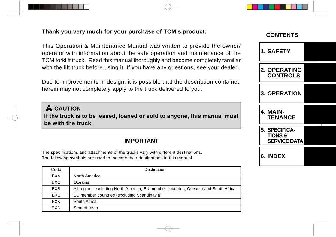
Thank you very much for your purchase of TCM’s product.
This Operation & Maintenance Manual was written to provide the owner/operator with information about the safe operation and maintenance of theTCM forklift truck. Read this manual thoroughly and become completely familiarwith the lift truck before using it. If you have any questions, see your dealer.
Due to improvements in design, it is possible that the description containedherein may not completely apply to the truck delivered to you.
CAUTIONIf the truck is to be leased, loaned or sold to anyone, this manual mustbe with the truck.
CONTENTS
1. SAFETY
2. OPERATINGCONTROLS
3. OPERATION
4. MAIN-TENANCE
5. SPECIFICA-TIONS &SERVICE DATAIMPORTANT
The specifications and attachments of the trucks vary with different destinations.The following symbols are used to indicate their destinations in this manual.
Code Destination
EXA North America
EXC Oceania
EXB All regions excluding North America, EU member countries, Oceania and South Africa
EXE EU member countries (excluding Scandinavia)
EXK South Africa
EXN Scandinavia
6. INDEX
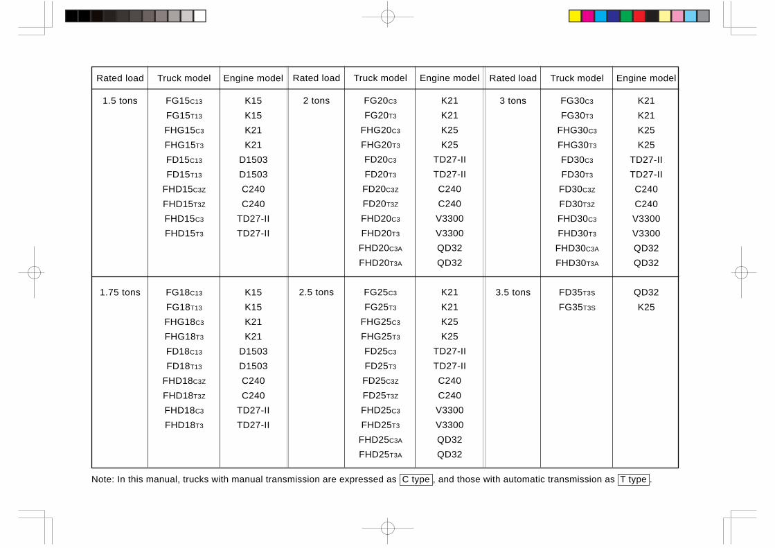
Note: In this manual, trucks with manual transmission are expressed as C type , and those with automatic transmission as T type .
Rated load Truck model Engine model
1.5 tons FG15C13 K15
FG15T13 K15
FHG15C3 K21
FHG15T3 K21
FD15C13 D1503
FD15T13 D1503
FHD15C3Z C240
FHD15T3Z C240
FHD15C3 TD27-II
FHD15T3 TD27-II
1.75 tons FG18C13 K15
FG18T13 K15
FHG18C3 K21
FHG18T3 K21
FD18C13 D1503
FD18T13 D1503
FHD18C3Z C240
FHD18T3Z C240
FHD18C3 TD27-II
FHD18T3 TD27-II
Rated load Truck model Engine model
3 tons FG30C3 K21
FG30T3 K21
FHG30C3 K25
FHG30T3 K25
FD30C3 TD27-II
FD30T3 TD27-II
FD30C3Z C240
FD30T3Z C240
FHD30C3 V3300
FHD30T3 V3300
FHD30C3A QD32
FHD30T3A QD32
3.5 tons FD35T3S QD32
FG35T3S K25
Rated load Truck model Engine model
2 tons FG20C3 K21
FG20T3 K21
FHG20C3 K25
FHG20T3 K25
FD20C3 TD27-II
FD20T3 TD27-II
FD20C3Z C240
FD20T3Z C240
FHD20C3 V3300
FHD20T3 V3300
FHD20C3A QD32
FHD20T3A QD32
2.5 tons FG25C3 K21
FG25T3 K21
FHG25C3 K25
FHG25T3 K25
FD25C3 TD27-II
FD25T3 TD27-II
FD25C3Z C240
FD25T3Z C240
FHD25C3 V3300
FHD25T3 V3300
FHD25C3A QD32
FHD25T3A QD32
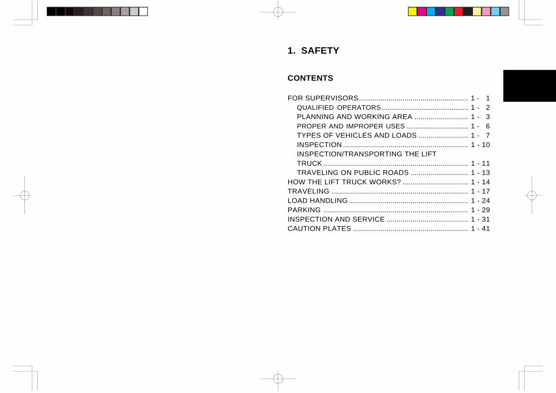
1. SAFETY
CONTENTS
FOR SUPERVISORS....................................................... 1 - 1QUALIFIED OPERATORS .............................................. 1 - 2PLANNING AND WORKING AREA ........................... 1 - 3PROPER AND IMPROPER USES ................................. 1 - 6TYPES OF VEHICLES AND LOADS ......................... 1 - 7INSPECTION ............................................................... 1 - 10INSPECTION/TRANSPORTING THE LIFTTRUCK ......................................................................... 1 - 11TRAVELING ON PUBLIC ROADS ............................. 1 - 13
HOW THE LIFT TRUCK WORKS? ................................. 1 - 14TRAVELING ..................................................................... 1 - 17LOAD HANDLING ............................................................ 1 - 24PARKING ......................................................................... 1 - 29INSPECTION AND SERVICE ......................................... 1 - 31CAUTION PLATES .......................................................... 1 - 41
1 - 1
FOR SUPERVISORS
Lift truck accidents cause dozens or hundreds of deaths everyyear, and even greater numbers of personal injuries.
TCM has steadily improved the design and fabrication of our lifttrucks so they may be used more safely and efficiently, but manyaccidents still occur due to improper use. Accidents are often theresult of more than just “bad driving”. The use of inappropriatetypes of equipment, the selection of inappropriate attachments oraccessories, inappropriate operating environments, carelessdesignation of operators, and failure to properly train the operatorare other common causes of accidents.
It is not possible to describe all potentially hazardous situationswhich may occur while operating, inspecting or servicing a forklifttruck. The warnings and cautions in this manual, including thedecals attached to the forklift, are not intended to cover all possibleworking hazards.If you operate, inspect or service the forklift in a manner notdescribed in this manual, please be careful because you do so atyour own risk.
This chapter covers the methods of accident prevention whichare primarily the responsibility of supervisory personnel.
• Pages 1 - 2 through 1 - 13 contain instructions which shouldbe enforced by the personnel supervising the operation of thelift truck. Please make sure the operators also read these pages.
• Page 1 - 14 and the following pages contain specific precautionsdirectly related to the operation of the lift truck.
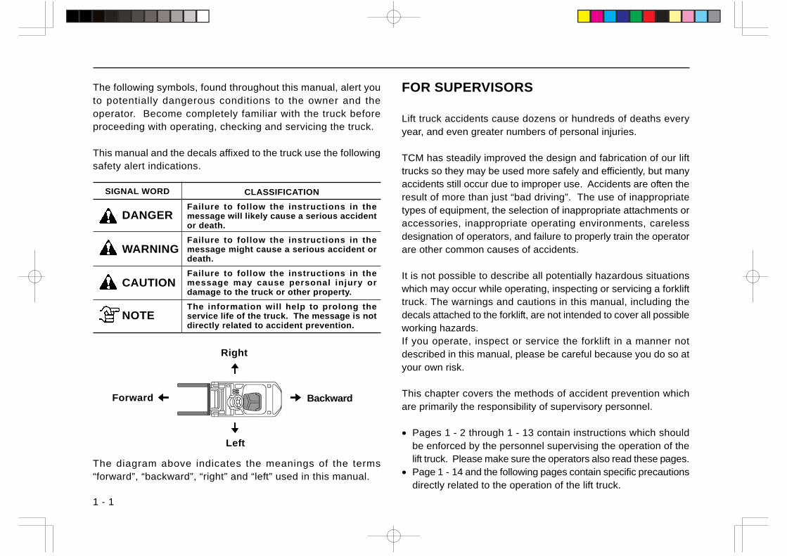
The following symbols, found throughout this manual, alert youto potentially dangerous conditions to the owner and theoperator. Become completely familiar with the truck beforeproceeding with operating, checking and servicing the truck.
This manual and the decals affixed to the truck use the followingsafety alert indications.
The diagram above indicates the meanings of the terms“forward”, “backward”, “right” and “left” used in this manual.
SIGNAL WORD CLASSIFICATION
Failure to follow the instructions in themessage will likely cause a serious accidentor death.
Failure to follow the instructions in themessage might cause a serious accident ordeath.
Failure to follow the instructions in themessage may cause personal injury ordamage to the truck or other property.
The information will help to prolong theservice life of the truck. The message is notdirectly related to accident prevention.
DANGER
WARNING
CAUTION
NOTE
Right
Left
Forward Backward
FOR SUPERVISORS QUALIFIED OPERATORS
1 - 2
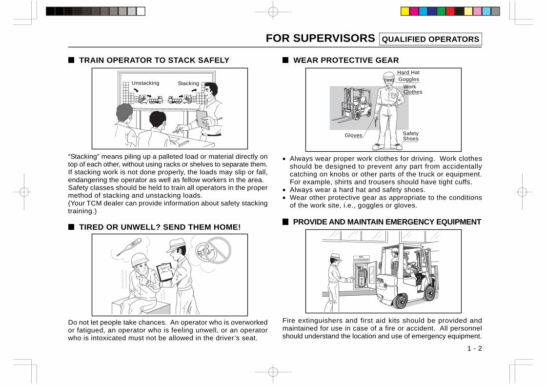
TIRED OR UNWELL? SEND THEM HOME!
Do not let people take chances. An operator who is overworkedor fatigued, an operator who is feeling unwell, or an operatorwho is intoxicated must not be allowed in the driver’s seat.
WEAR PROTECTIVE GEAR
• Always wear proper work clothes for driving. Work clothesshould be designed to prevent any part from accidentallycatching on knobs or other parts of the truck or equipment.For example, shirts and trousers should have tight cuffs.
• Always wear a hard hat and safety shoes.• Wear other protective gear as appropriate to the conditions
of the work site, i.e., goggles or gloves.
PROVIDE AND MAINTAIN EMERGENCY EQUIPMENT
Fire extinguishers and first aid kits should be provided andmaintained for use in case of a fire or accident. All personnelshould understand the location and use of emergency equipment.
TRAIN OPERATOR TO STACK SAFELY
“Stacking” means piling up a palleted load or material directly ontop of each other, without using racks or shelves to separate them.If stacking work is not done properly, the loads may slip or fall,endangering the operator as well as fellow workers in the area.Safety classes should be held to train all operators in the propermethod of stacking and unstacking loads.(Your TCM dealer can provide information about safety stackingtraining.)
Gloves SafetyShoes
WorkClothes
GogglesHard Hat
StackingUnstacking

FOR SUPERVISORS PLANNING AND WORKING AREA
1 - 3
KNOW WHO TO CALL IN AN EMERGENCY
Keep information on hand to allow immediate calls for help incase of a fire, accident or other emergency.
MAKE AN OPERATING PLAN AND DISCUSS IT
MARK THE TRAVEL LANES
Designate the travel lanes for the lift truck and mark them clearly,so they will be kept free of obstruction.
SET SPEED LIMITS
Set appropriate speed limits on your company grounds, andpost signs that are clearly visible.
(Example)
Yard SpeedLimit
Before using the lift truck, plan out the travel routes andoperating procedures, and thoroughly discuss the details withall involved personnel.
Contacts in emergency............................................................................ .............................. ............................
FOR SUPERVISORS PLANNING AND WORKING AREA
1 - 4
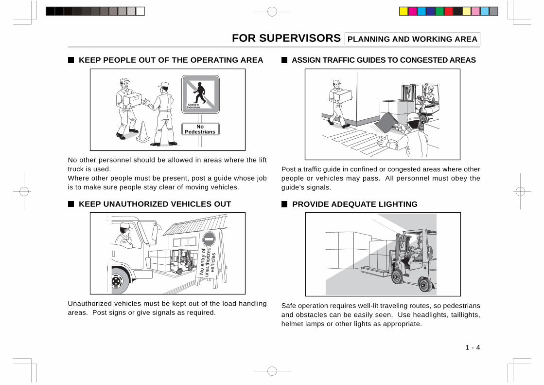
KEEP PEOPLE OUT OF THE OPERATING AREA
No other personnel should be allowed in areas where the lifttruck is used.Where other people must be present, post a guide whose jobis to make sure people stay clear of moving vehicles.
KEEP UNAUTHORIZED VEHICLES OUT
Unauthorized vehicles must be kept out of the load handlingareas. Post signs or give signals as required.
ASSIGN TRAFFIC GUIDES TO CONGESTED AREAS
Post a traffic guide in confined or congested areas where otherpeople or vehicles may pass. All personnel must obey theguide’s signals.
PROVIDE ADEQUATE LIGHTING
Safe operation requires well-lit traveling routes, so pedestriansand obstacles can be easily seen. Use headlights, taillights,helmet lamps or other lights as appropriate.
NoPedestrians
Closed toPedestrians
No
en
try
of
unau
thor
ized
veh
icle
s
FOR SUPERVISORS PLANNING AND WORKING AREA
1 - 5
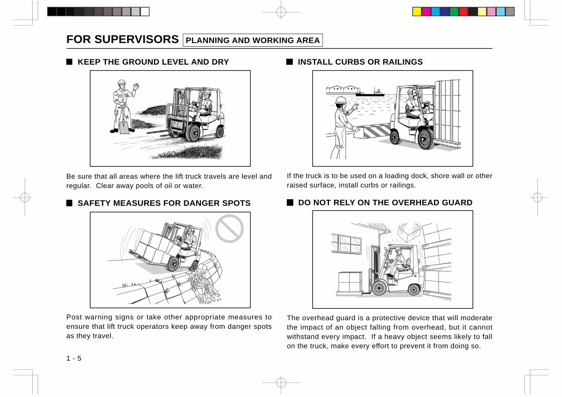
INSTALL CURBS OR RAILINGS
If the truck is to be used on a loading dock, shore wall or otherraised surface, install curbs or railings.
DO NOT RELY ON THE OVERHEAD GUARD
KEEP THE GROUND LEVEL AND DRY
Be sure that all areas where the lift truck travels are level andregular. Clear away pools of oil or water.
SAFETY MEASURES FOR DANGER SPOTS
Post warning signs or take other appropriate measures toensure that lift truck operators keep away from danger spotsas they travel.
The overhead guard is a protective device that will moderatethe impact of an object falling from overhead, but it cannotwithstand every impact. If a heavy object seems likely to fallon the truck, make every effort to prevent it from doing so.
FOR SUPERVISORS PROPER AND IMPROPER USES
1 - 6
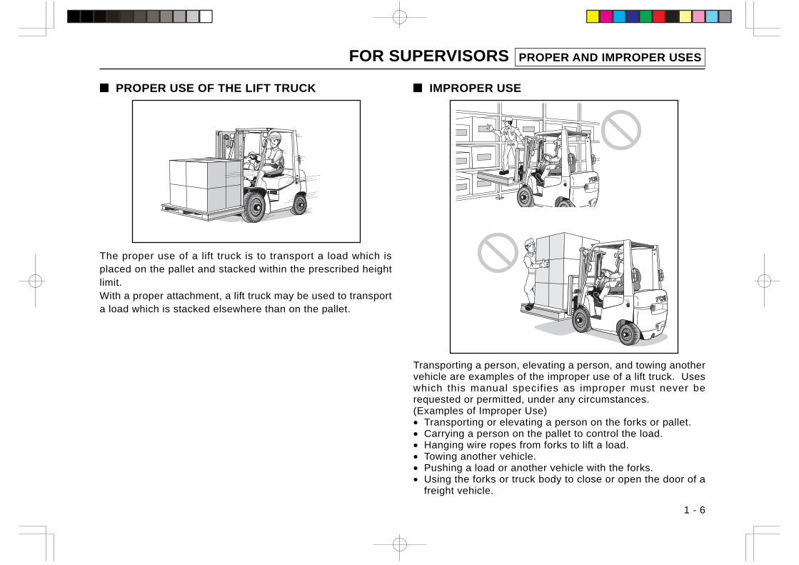
PROPER USE OF THE LIFT TRUCK
The proper use of a lift truck is to transport a load which isplaced on the pallet and stacked within the prescribed heightlimit.With a proper attachment, a lift truck may be used to transporta load which is stacked elsewhere than on the pallet.
IMPROPER USE
Transporting a person, elevating a person, and towing anothervehicle are examples of the improper use of a lift truck. Useswhich this manual specifies as improper must never berequested or permitted, under any circumstances.(Examples of Improper Use)• Transporting or elevating a person on the forks or pallet.• Carrying a person on the pallet to control the load.• Hanging wire ropes from forks to lift a load.• Towing another vehicle.• Pushing a load or another vehicle with the forks.• Using the forks or truck body to close or open the door of a
freight vehicle.
FOR SUPERVISORS TYPES OF VEHICLES AND LOADS
1 - 7
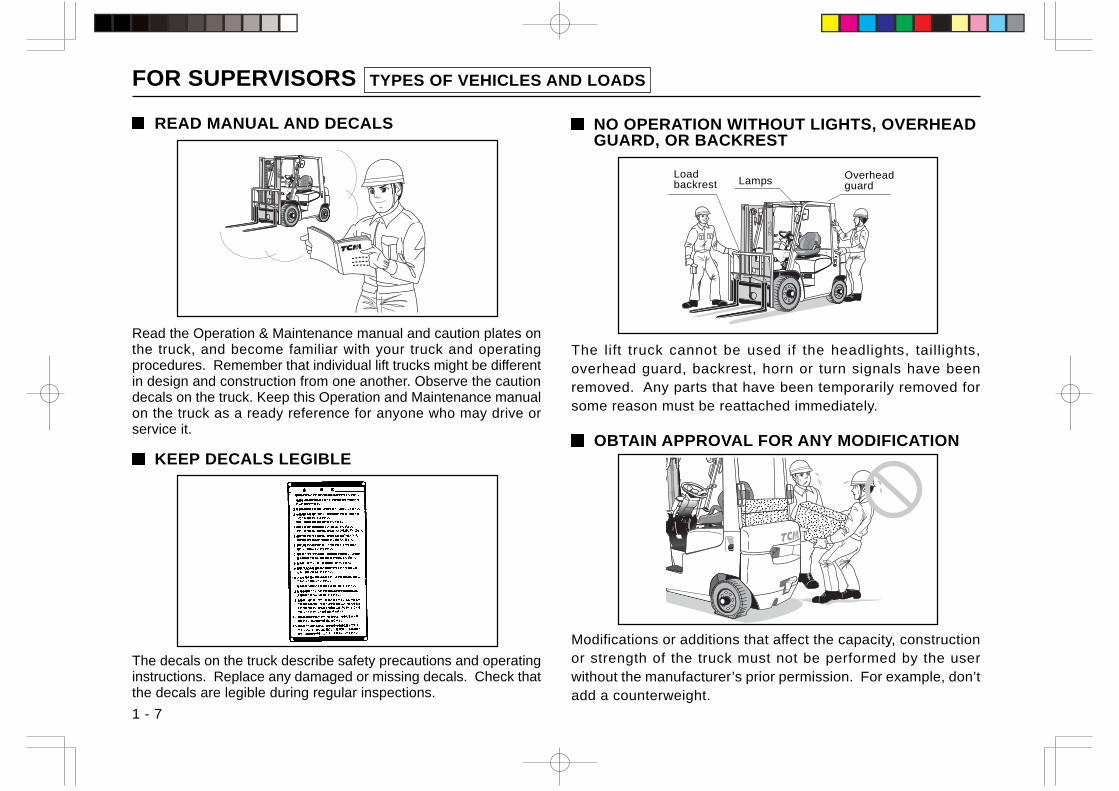
READ MANUAL AND DECALS NO OPERATION WITHOUT LIGHTS, OVERHEADGUARD, OR BACKREST
The lift truck cannot be used if the headlights, taillights,overhead guard, backrest, horn or turn signals have beenremoved. Any parts that have been temporarily removed forsome reason must be reattached immediately.
OBTAIN APPROVAL FOR ANY MODIFICATION
Modifications or additions that affect the capacity, constructionor strength of the truck must not be performed by the userwithout the manufacturer’s prior permission. For example, don’tadd a counterweight.
Read the Operation & Maintenance manual and caution plates onthe truck, and become familiar with your truck and operatingprocedures. Remember that individual lift trucks might be differentin design and construction from one another. Observe the cautiondecals on the truck. Keep this Operation and Maintenance manualon the truck as a ready reference for anyone who may drive orservice it.
KEEP DECALS LEGIBLE
The decals on the truck describe safety precautions and operatinginstructions. Replace any damaged or missing decals. Check thatthe decals are legible during regular inspections.
Loadbackrest
OverheadguardLamps
FOR SUPERVISORS TYPES OF VEHICLES AND LOADS
1 - 8
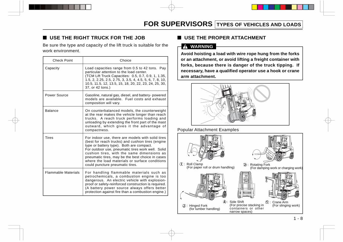
USE THE RIGHT TRUCK FOR THE JOB
Be sure the type and capacity of the lift truck is suitable for thework environment.
Avoid hoisting a load with wire rope hung from the forksor an attachment, or avoid lifting a freight container withforks, because there is danger of the truck tipping. Ifnecessary, have a qualified operator use a hook or cranearm attachment.
WARNING
USE THE PROPER ATTACHMENT
Popular Attachment Examples
: Crane Arm(For slinging work)
: Roll Clamp(For paper roll or drum handling)
: Rotating Fork(For damping work or charging work)
: Hinged Fork(for lumber handling)
: Side Shift(For precise stacking incontainers or othernarrow spaces)
Check Point
Capacity
Power Source
Balance
Tires
Flammable Materials
Choice
Load capacities range from 0.5 to 42 tons. Payparticular attention to the load center.(TCM Lift Truck Capacities: 0.5, 0.7, 0.9, 1, 1.35,1.5, 2, 2.25, 2.5, 2.75, 3, 3.5, 4, 4.5, 5, 6, 7, 8, 10,10.5, 11.5, 12, 13.5, 15, 18, 20, 22, 23, 24, 25, 30,37, or 42 tons.)
Gasoline, natural gas, diesel, and battery- poweredmodels are available. Fuel costs and exhaustcomposition will vary.
On counterbalanced models, the counterweightat the rear makes the vehicle longer than reachtrucks. A reach truck performs loading andunloading by extending the front part of the mastoutward, which g ives i t the advantage o fcompactness.
For indoor use, there are models with solid tires(best for reach trucks) and cushion tires (enginetype or battery type). Both are compact.For outdoor use, pneumatic tires work well. Solidcushion tires, with the same dimensions aspneumatic tires, may be the best choice in caseswhere the load materials or surface conditionscould puncture pneumatic tires.
For handl ing f lammable mater ials such aspetrochemicals, a combustion engine is toodangerous. An electric vehicle with explosion-proof or safety-reinforced construction is required.(A battery power source always offers betterprotection against fire than a combustion engine.)
FOR SUPERVISORS TYPES OF VEHICLES AND LOADS
1 - 9
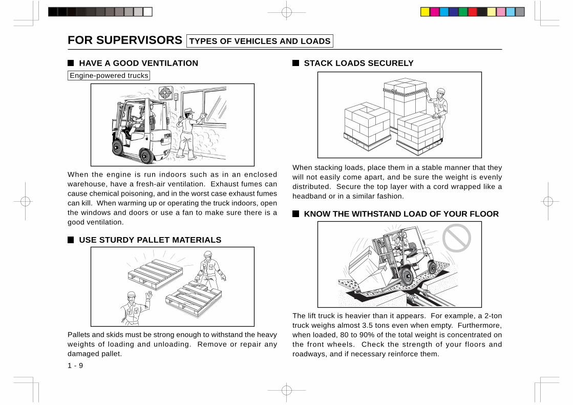
HAVE A GOOD VENTILATION
Engine-powered trucks
When the engine is run indoors such as in an enclosedwarehouse, have a fresh-air ventilation. Exhaust fumes cancause chemical poisoning, and in the worst case exhaust fumescan kill. When warming up or operating the truck indoors, openthe windows and doors or use a fan to make sure there is agood ventilation.
USE STURDY PALLET MATERIALS
Pallets and skids must be strong enough to withstand the heavyweights of loading and unloading. Remove or repair anydamaged pallet.
STACK LOADS SECURELY
When stacking loads, place them in a stable manner that theywill not easily come apart, and be sure the weight is evenlydistributed. Secure the top layer with a cord wrapped like aheadband or in a similar fashion.
KNOW THE WITHSTAND LOAD OF YOUR FLOOR
The lift truck is heavier than it appears. For example, a 2-tontruck weighs almost 3.5 tons even when empty. Furthermore,when loaded, 80 to 90% of the total weight is concentrated onthe front wheels. Check the strength of your floors androadways, and if necessary reinforce them.
FOR SUPERVISORS INSPECTION
1 - 10
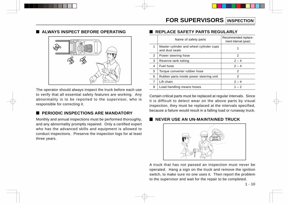
ALWAYS INSPECT BEFORE OPERATING
The operator should always inspect the truck before each useto verify that all essential safety features are working. Anyabnormality is to be reported to the supervisor, who isresponsible for correcting it.
PERIODIC INSPECTIONS ARE MANDATORY
Monthly and annual inspections must be performed thoroughly,and any abnormality promptly repaired. Only a certified expertwho has the advanced skills and equipment is allowed toconduct inspections. Preserve the inspection logs for at leastthree years.
REPLACE SAFETY PARTS REGULARLY
Name of safety partsRecommended replace-
ment interval (year)
1 Master cylinder and wheel cylinder cupsand dust seals
1
2 Power steering hose 2
3 Reserve tank tubing 2 – 4
4 Fuel hose 2 – 4
5 Torque converter rubber hose 2
6 Rubber parts inside power steering unit 2
7 Lift chain 2 – 4
8 Load handling means hoses 1 – 2
Certain critical parts must be replaced at regular intervals. Sinceit is difficult to detect wear on the above parts by visualinspection, they must be replaced at the intervals specified,because a failure would result in a falling load or runaway truck.
NEVER USE AN UN-MAINTAINED TRUCK
A truck that has not passed an inspection must never beoperated. Hang a sign on the truck and remove the ignitionswitch, to make sure no one uses it. Then report the problemto the supervisor and wait for the repair to be completed.
Out ofService
FOR SUPERVISORS INSPECTION/TRANSPORTING THE LIFT TRUCK
1 - 11
DESIGNATE A REPAIR AND ASSEMBLYSUPERVISOR
Repairs and the mounting and dismounting of attachments mustbe performed under the direction of a designated supervisor.The body and major parts of the lift truck are quite heavy andunder very high pressure. Repair or assembly work undertakenwithout careful and thorough preparation can lead to seriousinjury.
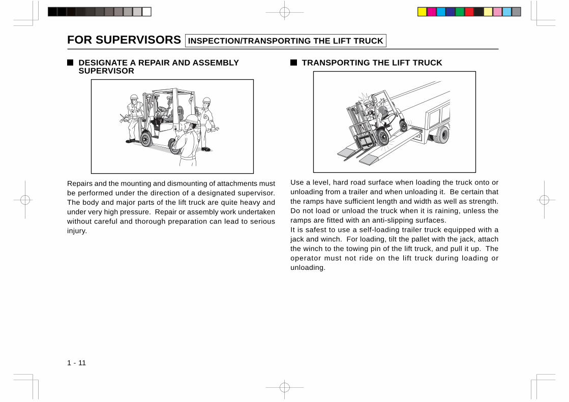
TRANSPORTING THE LIFT TRUCK
Use a level, hard road surface when loading the truck onto orunloading from a trailer and when unloading it. Be certain thatthe ramps have sufficient length and width as well as strength.Do not load or unload the truck when it is raining, unless theramps are fitted with an anti-slipping surfaces.It is safest to use a self-loading trailer truck equipped with ajack and winch. For loading, tilt the pallet with the jack, attachthe winch to the towing pin of the lift truck, and pull it up. Theoperator must not ride on the lift truck during loading orunloading.
FOR SUPERVISORS INSPECTION/TRANSPORTING THE LIFT TRUCK
1 - 12
WARNING
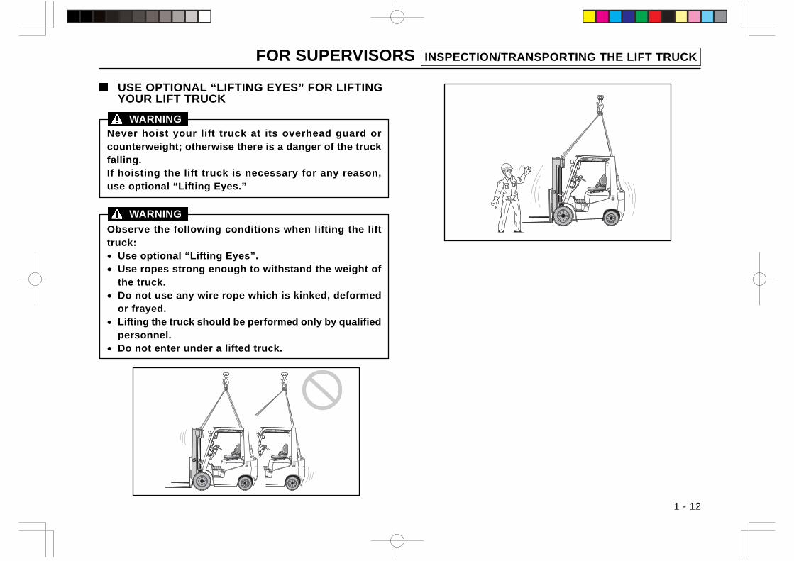
USE OPTIONAL “LIFTING EYES” FOR LIFTINGYOUR LIFT TRUCK
Never hoist your lift truck at its overhead guard orcounterweight; otherwise there is a danger of the truckfalling.If hoisting the lift truck is necessary for any reason,use optional “Lifting Eyes.”
WARNING
Observe the following conditions when lifting the lifttruck:• Use optional “Lifting Eyes”.• Use ropes strong enough to withstand the weight of
the truck.• Do not use any wire rope which is kinked, deformed
or frayed.• Lifting the truck should be performed only by qualified
personnel.• Do not enter under a lifted truck.
FOR SUPERVISORS TRAVELING ON PUBLIC ROADS
1 - 13
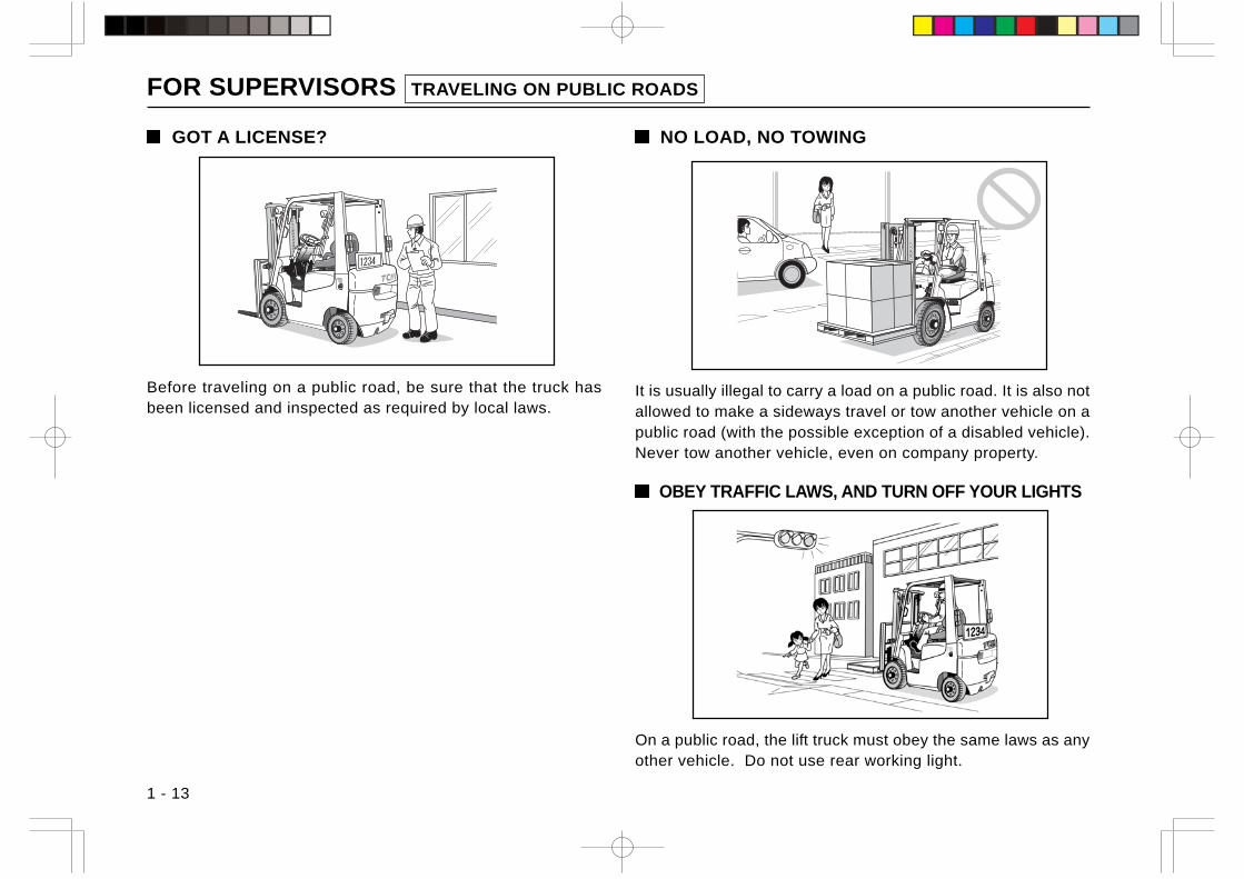
GOT A LICENSE?
Before traveling on a public road, be sure that the truck hasbeen licensed and inspected as required by local laws.
NO LOAD, NO TOWING
It is usually illegal to carry a load on a public road. It is also notallowed to make a sideways travel or tow another vehicle on apublic road (with the possible exception of a disabled vehicle).Never tow another vehicle, even on company property.
OBEY TRAFFIC LAWS, AND TURN OFF YOUR LIGHTS
On a public road, the lift truck must obey the same laws as anyother vehicle. Do not use rear working light.
HOW THE LIFT TRUCK WORKS?
1 - 14
Lift truck viewed from front
The higher theload, the higherthe truck’s centerof gravity
Truck’s center ofgravity with trucktilted
Truck’s center of gravitywith standard mastraised
Truck’s center ofgravity with highmast raised
Load center (from fork root) mm
Load’scentergravity
Distance
Allo
wa
ble
loa
d (k
g)
Weight x distance x moment(constant)
Basic load center
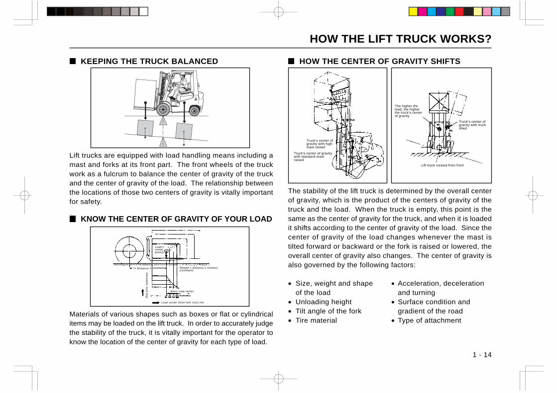
KEEPING THE TRUCK BALANCED
Materials of various shapes such as boxes or flat or cylindricalitems may be loaded on the lift truck. In order to accurately judgethe stability of the truck, it is vitally important for the operator toknow the location of the center of gravity for each type of load.
Lift trucks are equipped with load handling means including amast and forks at its front part. The front wheels of the truckwork as a fulcrum to balance the center of gravity of the truckand the center of gravity of the load. The relationship betweenthe locations of those two centers of gravity is vitally importantfor safety.
KNOW THE CENTER OF GRAVITY OF YOUR LOAD
HOW THE CENTER OF GRAVITY SHIFTS
The stability of the lift truck is determined by the overall centerof gravity, which is the product of the centers of gravity of thetruck and the load. When the truck is empty, this point is thesame as the center of gravity for the truck, and when it is loadedit shifts according to the center of gravity of the load. Since thecenter of gravity of the load changes whenever the mast istilted forward or backward or the fork is raised or lowered, theoverall center of gravity also changes. The center of gravity isalso governed by the following factors:
• Size, weight and shape • Acceleration, decelerationof the load and turning
• Unloading height • Surface condition and• Tilt angle of the fork gradient of the road• Tire material • Type of attachment
HOW THE LIFT TRUCK WORKS?
1 - 15
Axis of lateral stability
Lift truck Viewed from Above
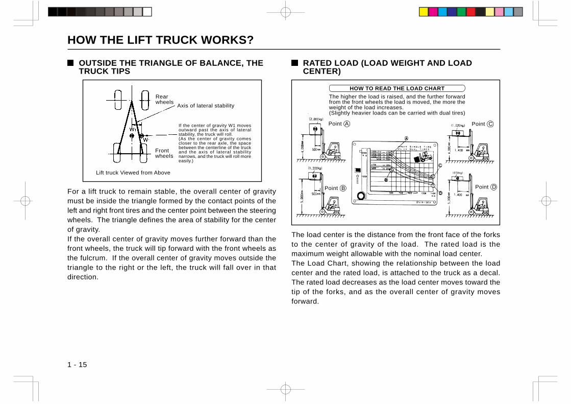
HOW TO READ THE LOAD CHART
The higher the load is raised, and the further forwardfrom the front wheels the load is moved, the more theweight of the load increases.(Slightly heavier loads can be carried with dual tires)
Rearwheels
Frontwheels
Point D
Point CPoint A
Point B
OUTSIDE THE TRIANGLE OF BALANCE, THETRUCK TIPS
RATED LOAD (LOAD WEIGHT AND LOADCENTER)
For a lift truck to remain stable, the overall center of gravitymust be inside the triangle formed by the contact points of theleft and right front tires and the center point between the steeringwheels. The triangle defines the area of stability for the centerof gravity.If the overall center of gravity moves further forward than thefront wheels, the truck will tip forward with the front wheels asthe fulcrum. If the overall center of gravity moves outside thetriangle to the right or the left, the truck will fall over in thatdirection.
The load center is the distance from the front face of the forksto the center of gravity of the load. The rated load is themaximum weight allowable with the nominal load center.The Load Chart, showing the relationship between the loadcenter and the rated load, is attached to the truck as a decal.The rated load decreases as the load center moves toward thetip of the forks, and as the overall center of gravity movesforward.
If the center of gravity W1 movesoutward past the axis of lateralstability, the truck will roll.(As the center of gravity comescloser to the rear axle, the spacebetween the centerline of the truckand the axis of lateral stabil itynarrows, and the truck will roll moreeasily.)
HOW THE LIFT TRUCK WORKS?
1 - 16
ACCELERATING, DECELERATING ANDTURNING
The principle of inertia provides that a stationary object willremain stationary as long as there is no external force actingon it, and that a moving object will continue moving at a constantspeed as long as there is no external force acting on it.Due to inertia, when the lift truck starts to move there is amomentary backward force, and when it stops there is amomentary forward force. As a result, if the brakes are appliedsuddenly, there is a very strong hazard that the forward forcewill become strong enough for the truck to tip forward.Likewise, when the truck is turning there is a centrifugal forcethat pulls it outward from the turning center. This force cancause the truck to fall sideways. Since the zone of lateralstability is especially narrow, it is necessary to slow downsubstantially when turning in order to prevent the truck fromtipping.When the load is elevated the overall center of gravity is raised,increasing the danger of the truck tipping over to the front orside.
TRAVELING
1 - 17
Do not operate the lift truck until preoperationalchecks are finished
If any defect is found during checking, report it to the supervisorand have it repaired.Do not operate the truck until the malfunction or damage is properlyrepaired.
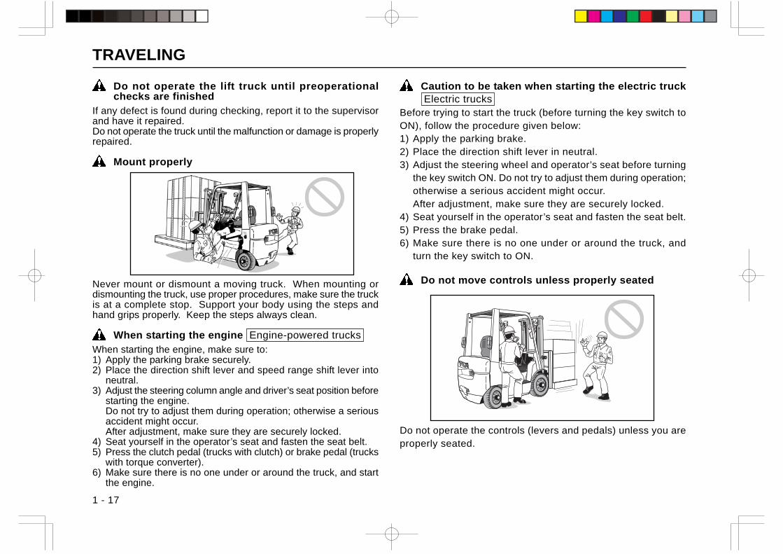
Mount properly
Never mount or dismount a moving truck. When mounting ordismounting the truck, use proper procedures, make sure the truckis at a complete stop. Support your body using the steps andhand grips properly. Keep the steps always clean.
When starting the engine Engine-powered trucksWhen starting the engine, make sure to:1) Apply the parking brake securely.2) Place the direction shift lever and speed range shift lever into
neutral.3) Adjust the steering column angle and driver’s seat position before
starting the engine.Do not try to adjust them during operation; otherwise a seriousaccident might occur.After adjustment, make sure they are securely locked.
4) Seat yourself in the operator’s seat and fasten the seat belt.5) Press the clutch pedal (trucks with clutch) or brake pedal (trucks
with torque converter).6) Make sure there is no one under or around the truck, and start
the engine.
Caution to be taken when starting the electric truck Electric trucks
Before trying to start the truck (before turning the key switch toON), follow the procedure given below:1) Apply the parking brake.2) Place the direction shift lever in neutral.3) Adjust the steering wheel and operator’s seat before turning
the key switch ON. Do not try to adjust them during operation;otherwise a serious accident might occur.After adjustment, make sure they are securely locked.
4) Seat yourself in the operator’s seat and fasten the seat belt.5) Press the brake pedal.6) Make sure there is no one under or around the truck, and
turn the key switch to ON.
Do not move controls unless properly seated
Do not operate the controls (levers and pedals) unless you areproperly seated.
TRAVELING
1 - 18
Sound horn when starting
Before starting, make sure no one is near the truck. Let otherworkmen and bystanders know you are starting up by soundinghorn.
Keep your hands clean
It is dangerous to operate the steering wheel and levers withgreasy hands. If grease, oil or soil is sticking to your hands,clean if off.
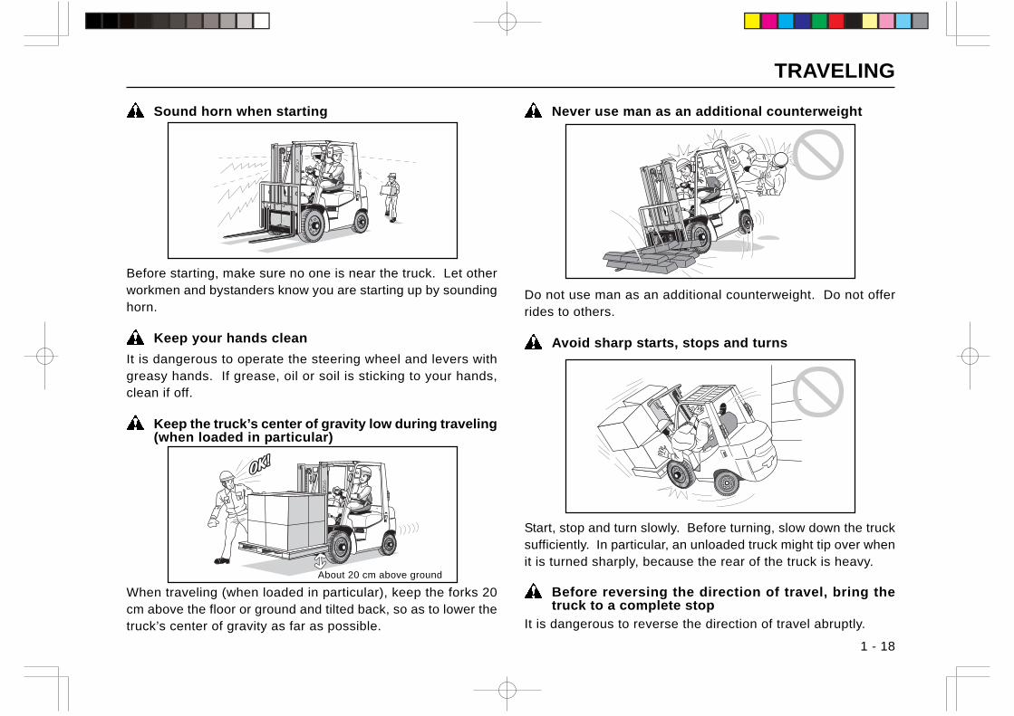
Keep the truck’s center of gravity low during traveling(when loaded in particular)
When traveling (when loaded in particular), keep the forks 20cm above the floor or ground and tilted back, so as to lower thetruck’s center of gravity as far as possible.
Never use man as an additional counterweight
Do not use man as an additional counterweight. Do not offerrides to others.
Avoid sharp starts, stops and turns
Start, stop and turn slowly. Before turning, slow down the trucksufficiently. In particular, an unloaded truck might tip over whenit is turned sharply, because the rear of the truck is heavy.
Before reversing the direction of travel, bring thetruck to a complete stop
It is dangerous to reverse the direction of travel abruptly.
About 20 cm above ground
TRAVELING
1 - 19
Carry the load lowIt is dangerous to travel with forks lifted higher than isappropriate, regardless of whether loaded or not. Keep theload as low as possible while traveling. Do not turn the truckwith the load raised high.
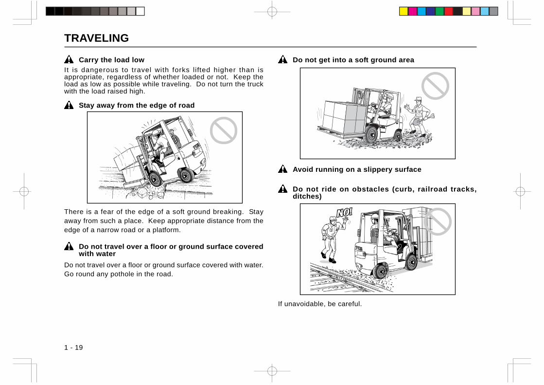
Stay away from the edge of road
There is a fear of the edge of a soft ground breaking. Stayaway from such a place. Keep appropriate distance from theedge of a narrow road or a platform.
Do not travel over a floor or ground surface coveredwith water
Do not travel over a floor or ground surface covered with water.Go round any pothole in the road.
Do not get into a soft ground area
Avoid running on a slippery surface
Do not ride on obstacles (curb, railroad tracks,ditches)
If unavoidable, be careful.
TRAVELING
1 - 20
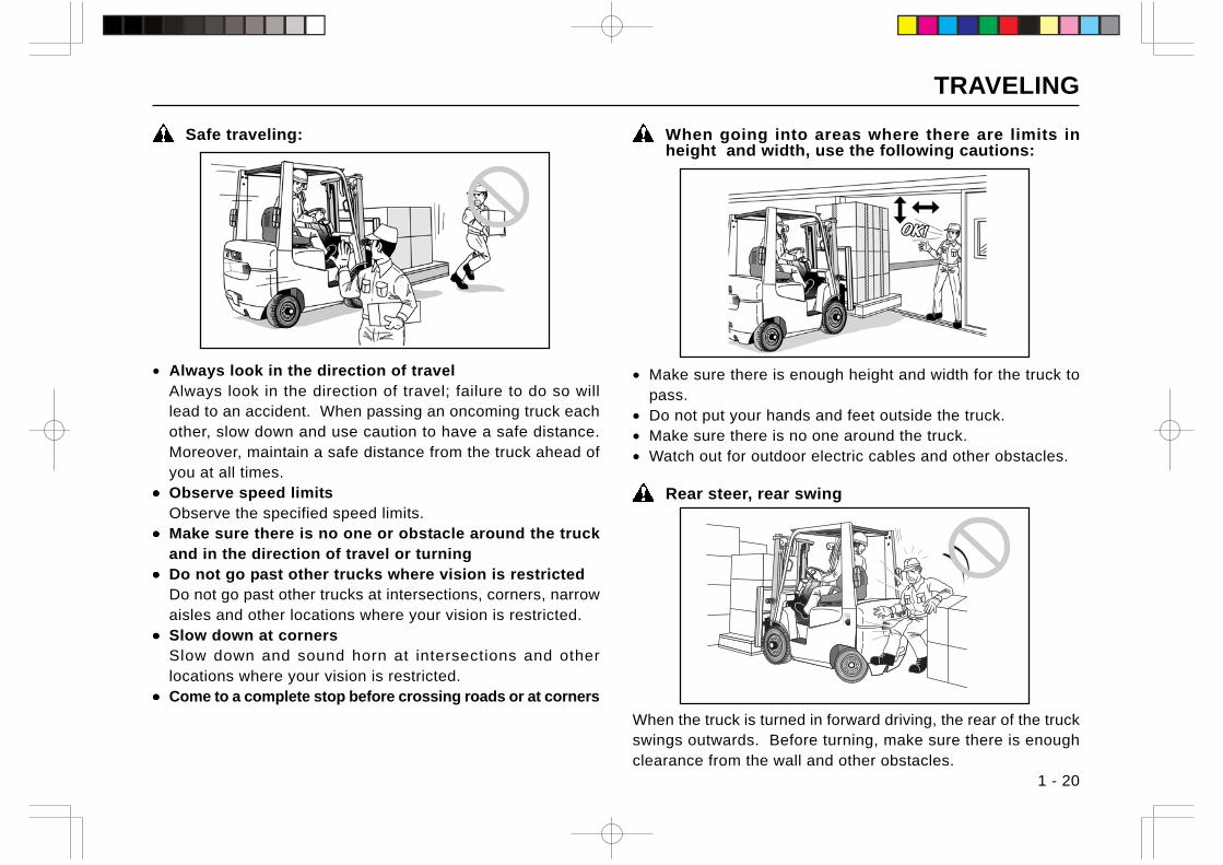
Safe traveling:
• Always look in the direction of travelAlways look in the direction of travel; failure to do so willlead to an accident. When passing an oncoming truck eachother, slow down and use caution to have a safe distance.Moreover, maintain a safe distance from the truck ahead ofyou at all times.
••••• Observe speed limitsObserve the specified speed limits.
••••• Make sure there is no one or obstacle around the truckand in the direction of travel or turning
••••• Do not go past other trucks where vision is restrictedDo not go past other trucks at intersections, corners, narrowaisles and other locations where your vision is restricted.
••••• Slow down at cornersSlow down and sound horn at intersections and otherlocations where your vision is restricted.
••••• Come to a complete stop before crossing roads or at corners
When going into areas where there are limits inheight and width, use the following cautions:
• Make sure there is enough height and width for the truck topass.
• Do not put your hands and feet outside the truck.• Make sure there is no one around the truck.• Watch out for outdoor electric cables and other obstacles.
Rear steer, rear swing
When the truck is turned in forward driving, the rear of the truckswings outwards. Before turning, make sure there is enoughclearance from the wall and other obstacles.
TRAVELING
1 - 21
Have a guide when handling bulky loads
When handling bulky loads which restrict your vision, operatethe truck in reverse and have a guide.
Reverse travel
When traveling in reverse, always look in the direction of travel.Do not rely too much on the sideview mirrors (if so equipped)and backup buzzer.
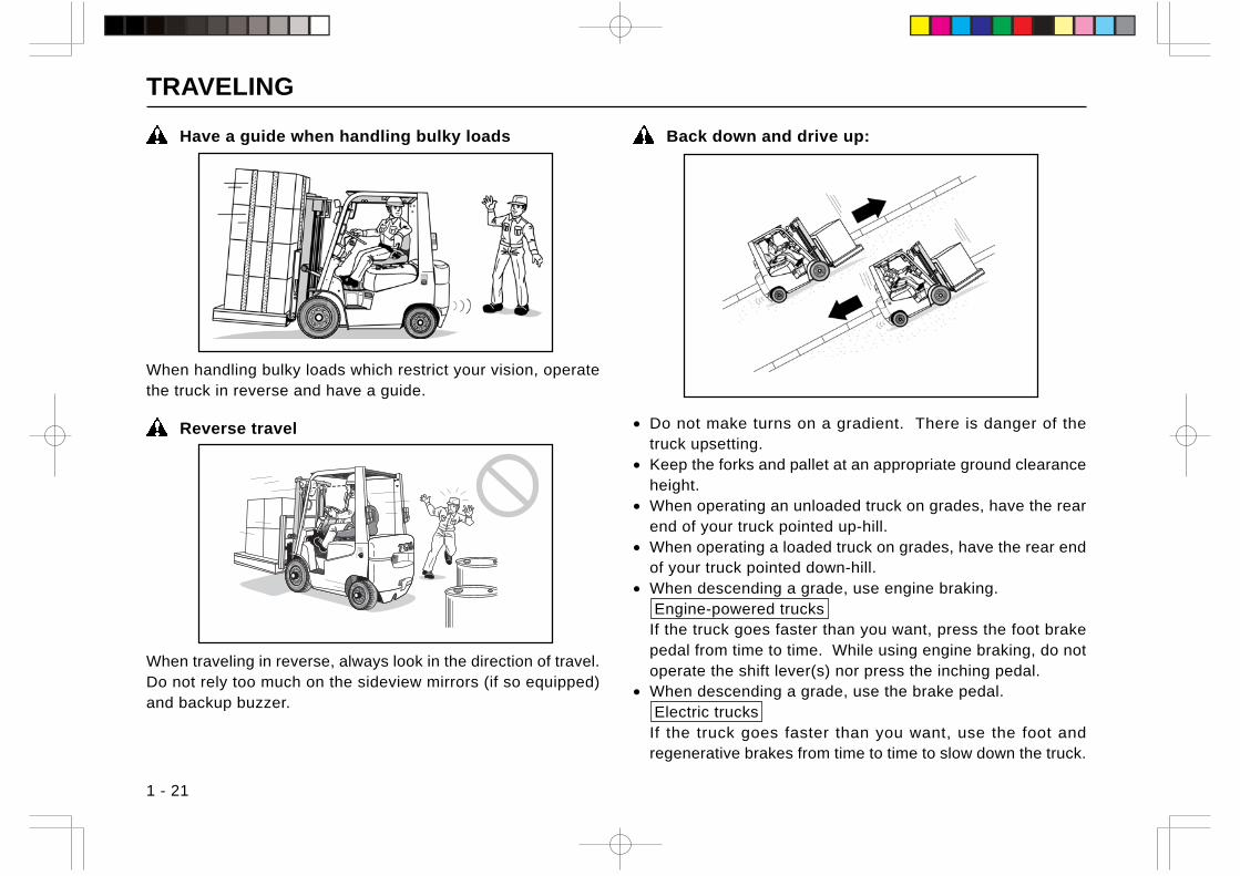
Back down and drive up:
• Do not make turns on a gradient. There is danger of thetruck upsetting.
• Keep the forks and pallet at an appropriate ground clearanceheight.
• When operating an unloaded truck on grades, have the rearend of your truck pointed up-hill.
• When operating a loaded truck on grades, have the rear endof your truck pointed down-hill.
• When descending a grade, use engine braking. Engine-powered trucksIf the truck goes faster than you want, press the foot brakepedal from time to time. While using engine braking, do notoperate the shift lever(s) nor press the inching pedal.
• When descending a grade, use the brake pedal. Electric trucksIf the truck goes faster than you want, use the foot andregenerative brakes from time to time to slow down the truck.
TRAVELING
1 - 22
Brake the truck in good time
The truck takes a little longer to come to a stop on a slipperysurface than on a usual surface. Brake the truck in good time.In addition, the stopping distance of the truck is longer on adownhill. Keep the traveling speed under your control.
Do not shut off the engine during traveling(trucks with power steering and power brake)
Engine-powered trucks
If the engine stops during traveling, both the power steeringunit and the power brake goes inoperative.
Do not turning off key switch during traveling
Electric trucks
If the key switch is turned off during traveling, power steeringbecomes disabled to make steering hard.
Engine braking is not available when the inchingpedal is pressed
Engine-powered trucks
When the inching pedal is pressed to the bottom, the brake isapplied to the truck, but engine braking is not available becausethe clutch unit is disengaged.
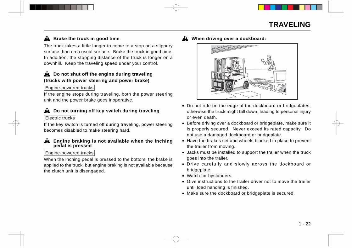
When driving over a dockboard:
• Do not ride on the edge of the dockboard or bridgeplates;otherwise the truck might fall down, leading to personal injuryor even death.
• Before driving over a dockboard or bridgeplate, make sure itis properly secured. Never exceed its rated capacity. Donot use a damaged dockboard or bridgeplate.
• Have the brakes set and wheels blocked in place to preventthe trailer from moving.
• Jacks must be installed to support the trailer when the truckgoes into the trailer.
• Drive careful ly and slowly across the dockboard orbridgeplate.
• Watch for bystanders.• Give instructions to the trailer driver not to move the trailer
until load handling is finished.• Make sure the dockboard or bridgeplate is secured.
TRAVELING
1 - 23
Know the load bearing capacity of the floor
Before entering a building or going into an elevator, make surethe floor is strong enough to withstand the weights of the truckand the loads.
Practice safe driving and load handling techniques
Before using the lift truck, you must practice safe driving andload handling techniques. Even after getting familiar with theoperation of the truck, operate the truck carefully; recklessdriving and operation will cause a personal injury or an accident.
When using multiple trucks
When operating multiple trucks, remember that their operatingcontrols have their own characteristics even if the trucks are ofthe same specification. If you change the trucks, keep thispoint in mind. In particular, pay attention to the brake system.
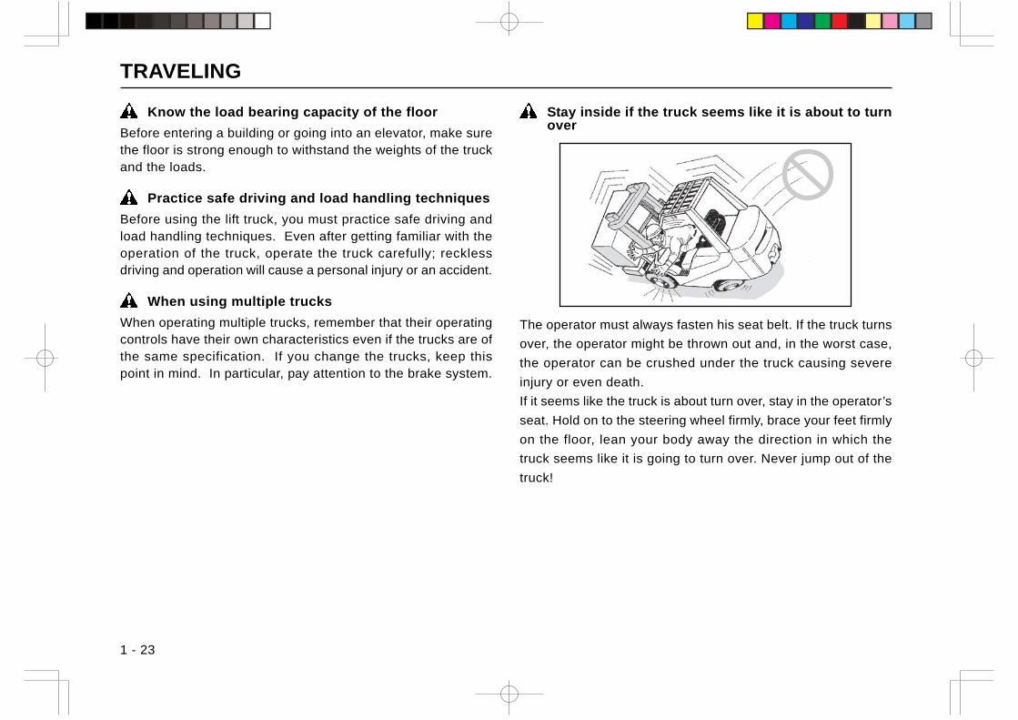
Stay inside if the truck seems like it is about to turnover
The operator must always fasten his seat belt. If the truck turns
over, the operator might be thrown out and, in the worst case,
the operator can be crushed under the truck causing severe
injury or even death.
If it seems like the truck is about turn over, stay in the operator’s
seat. Hold on to the steering wheel firmly, brace your feet firmly
on the floor, lean your body away the direction in which the
truck seems like it is going to turn over. Never jump out of the
truck!
LOAD HANDLING
1 - 24
Keep anyone but a guide away from the working area
Do not let other persons or truck approach your lifttruck during operation
When working in a group, have a person present togive guidance and follow his instructions
Do not use your truck for purposes other thanspecified:
• Do not use the truck to open or close the doors of freightcars or warehouses.
• Do not push other trucks.• Do not hoist loads, using ropes hung on the forks.• Do not tow another vehicle using the draw bar.• Do not push or pull loads with forks; otherwise, the load might
fall off or get damaged. In particular, the truck with the max. liftheight of more than 150 cm might tip over, if you try to do that.
Pay attention to the fork tips
The fork tips are sharp and could cause personal injury. Inaddition, if they catch on obstructions, the truck might losecontrol, leading to an accident.
Adjust fork spacing properly
Adjust the fork spacing suitable according to the size of theload.
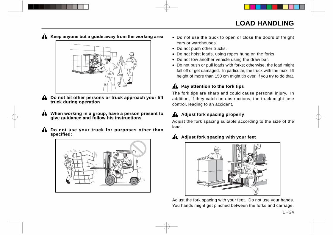
Adjust fork spacing with your feet
Adjust the fork spacing with your feet. Do not use your hands.You hands might get pinched between the forks and carriage.
LOAD HANDLING
1 - 25
Make sure forks are securely locked
After adjusting the fork spacing, lock the forks with fork stoppers.Unlocked forks will slide during traveling, causing the load tofall off.
Do not put your hands or feet into the load handlingsystem
Never put your hands or feet on the mast or mastconnecting members; otherwise your hands or feet mightbe cut if the mast moves unexpectedly.
Never elevate a man
Never allow other person(s) to ride on the forks. He mightfall off the forks, getting injured.
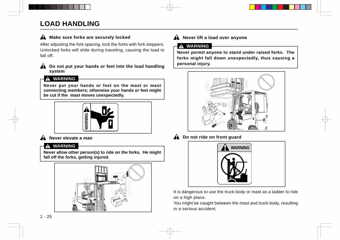
Never lift a load over anyone
Never permit anyone to stand under raised forks. Theforks might fall down unexpectedly, thus causing apersonal injury.
WARNING
Do not ride on front guard
It is dangerous to use the truck body or mast as a ladder to rideon a high place.You might be caught between the mast and truck body, resultingin a serious accident.
WARNING
WARNING WARNING
WA
RN
ING
LOAD HANDLING
1 - 26
Do not pick up loads from other truck
Do not pick up loads from raised forks of other truck. Thismight cause an off-centered load or the load to fall off.
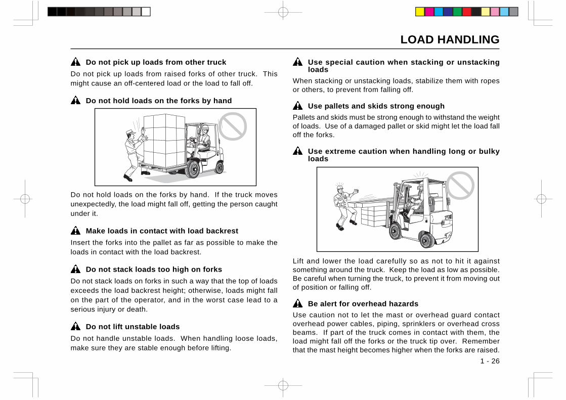
Do not hold loads on the forks by hand
Use special caution when stacking or unstackingloads
When stacking or unstacking loads, stabilize them with ropesor others, to prevent from falling off.
Use pallets and skids strong enough
Pallets and skids must be strong enough to withstand the weightof loads. Use of a damaged pallet or skid might let the load falloff the forks.
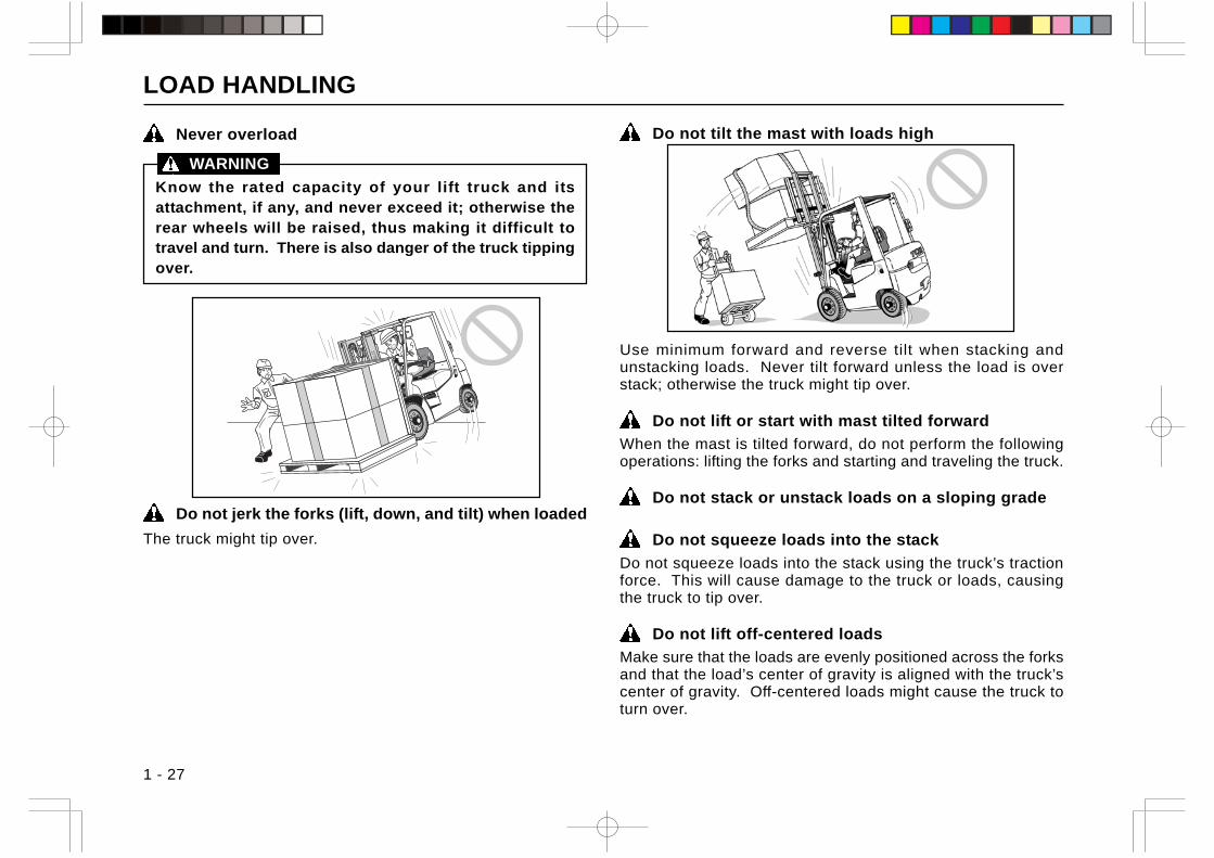
Use extreme caution when handling long or bulkyloads
Do not hold loads on the forks by hand. If the truck movesunexpectedly, the load might fall off, getting the person caughtunder it.
Make loads in contact with load backrest
Insert the forks into the pallet as far as possible to make theloads in contact with the load backrest.
Do not stack loads too high on forks
Do not stack loads on forks in such a way that the top of loadsexceeds the load backrest height; otherwise, loads might fallon the part of the operator, and in the worst case lead to aserious injury or death.
Do not lift unstable loads
Do not handle unstable loads. When handling loose loads,make sure they are stable enough before lifting.
Lift and lower the load carefully so as not to hit it againstsomething around the truck. Keep the load as low as possible.Be careful when turning the truck, to prevent it from moving outof position or falling off.
Be alert for overhead hazards
Use caution not to let the mast or overhead guard contactoverhead power cables, piping, sprinklers or overhead crossbeams. If part of the truck comes in contact with them, theload might fall off the forks or the truck tip over. Rememberthat the mast height becomes higher when the forks are raised.
LOAD HANDLING
1 - 27
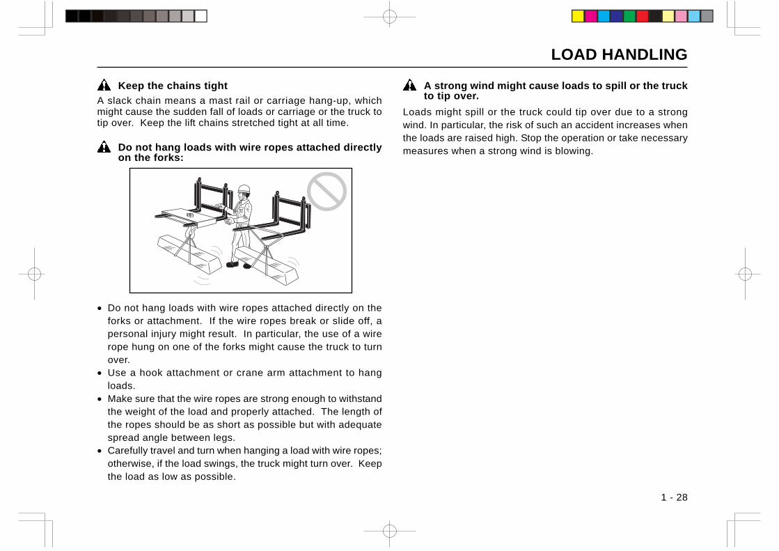
Never overload
Know the rated capacity of your lift truck and itsattachment, if any, and never exceed it; otherwise therear wheels will be raised, thus making it difficult totravel and turn. There is also danger of the truck tippingover.
Do not jerk the forks (lift, down, and tilt) when loaded
The truck might tip over.
WARNING
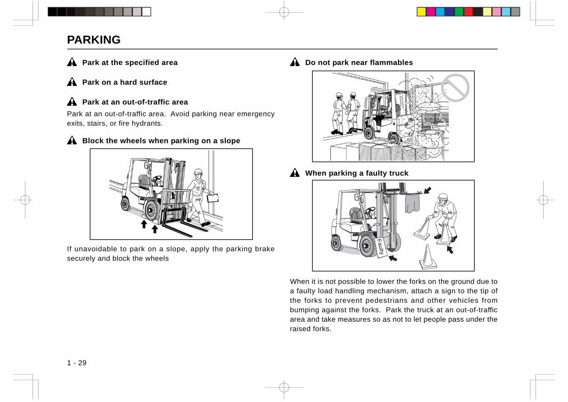
Do not tilt the mast with loads high
Use minimum forward and reverse tilt when stacking andunstacking loads. Never tilt forward unless the load is overstack; otherwise the truck might tip over.
Do not lift or start with mast tilted forward
When the mast is tilted forward, do not perform the followingoperations: lifting the forks and starting and traveling the truck.
Do not stack or unstack loads on a sloping grade
Do not squeeze loads into the stack
Do not squeeze loads into the stack using the truck’s tractionforce. This will cause damage to the truck or loads, causingthe truck to tip over.
Do not lift off-centered loads
Make sure that the loads are evenly positioned across the forksand that the load’s center of gravity is aligned with the truck’scenter of gravity. Off-centered loads might cause the truck toturn over.
LOAD HANDLING
1 - 28
Keep the chains tight
A slack chain means a mast rail or carriage hang-up, whichmight cause the sudden fall of loads or carriage or the truck totip over. Keep the lift chains stretched tight at all time.
Do not hang loads with wire ropes attached directlyon the forks:
• Do not hang loads with wire ropes attached directly on theforks or attachment. If the wire ropes break or slide off, apersonal injury might result. In particular, the use of a wirerope hung on one of the forks might cause the truck to turnover.
• Use a hook attachment or crane arm attachment to hangloads.
• Make sure that the wire ropes are strong enough to withstandthe weight of the load and properly attached. The length ofthe ropes should be as short as possible but with adequatespread angle between legs.
• Carefully travel and turn when hanging a load with wire ropes;otherwise, if the load swings, the truck might turn over. Keepthe load as low as possible.
A strong wind might cause loads to spill or the truckto tip over.
Loads might spill or the truck could tip over due to a strongwind. In particular, the risk of such an accident increases whenthe loads are raised high. Stop the operation or take necessarymeasures when a strong wind is blowing.
PARKING
1 - 29
Park at the specified area
Park on a hard surface
Park at an out-of-traffic area
Park at an out-of-traffic area. Avoid parking near emergencyexits, stairs, or fire hydrants.
Block the wheels when parking on a slope
Do not park near flammables
When parking a faulty truck
When it is not possible to lower the forks on the ground due toa faulty load handling mechanism, attach a sign to the tip ofthe forks to prevent pedestrians and other vehicles frombumping against the forks. Park the truck at an out-of-trafficarea and take measures so as not to let people pass under theraised forks.
If unavoidable to park on a slope, apply the parking brakesecurely and block the wheels
Fa
ulty
PARKING
1 - 30
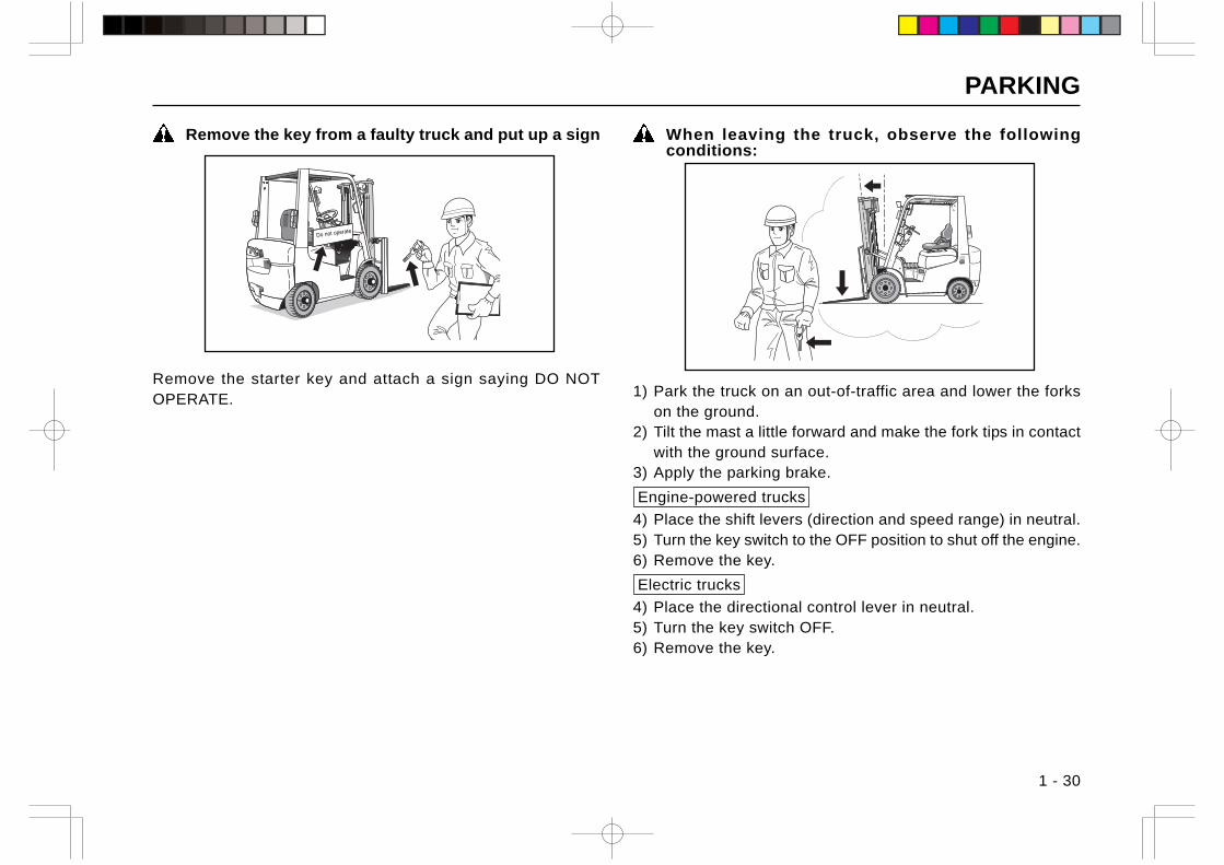
Remove the key from a faulty truck and put up a sign When leaving the truck, observe the followingconditions:
Remove the starter key and attach a sign saying DO NOTOPERATE. 1) Park the truck on an out-of-traffic area and lower the forks
on the ground.2) Tilt the mast a little forward and make the fork tips in contact
with the ground surface.3) Apply the parking brake.
Engine-powered trucks
4) Place the shift levers (direction and speed range) in neutral.5) Turn the key switch to the OFF position to shut off the engine.6) Remove the key.
Electric trucks
4) Place the directional control lever in neutral.5) Turn the key switch OFF.6) Remove the key.
Do not operate
INSPECTION AND SERVICE
1 - 31
Inspection and maintenance must be performed onlyby qualified personnel
Inspection and maintenance of the truck should beperformed only by qualified and authorized personnel.Improper inspection, maintenance or repairs will causedamage to the truck or a serious accident.
Wipe any spilt oil or grease
Wipe any spilt oil or grease. If the truck is contaminated withoil or grease, it is difficult for you to find possible cracks orother defects.
No fire (when handling lubricants, batteries, clothwetted with oil)
No fire. Never smoke or use fire or naked flame when handlinglubricants, batteries or cloth wetted with oil.
Use appropriate tools
Use appropriate tools suitable for the job you have beenassigned. Use of inappropriate tools might cause a seriousaccident.
Do not use tools for purposes other than specified
Do not use tools for purposes other than specified. It can causea serious accident.
Avoid loose fitting clothing
Wear protective clothing called for by job conditions.
Wear safety gear devices (hard hat, safety shoes,safety glasses, gloves)
Park on a hard, level groundBefore performing inspection and maintenance, make sure topark the truck on a hard, level surface. Also make sure theplace is dry and without dust.
Have a good ventilationWhen performing inspection and maintenance indoors, have agood ventilation.
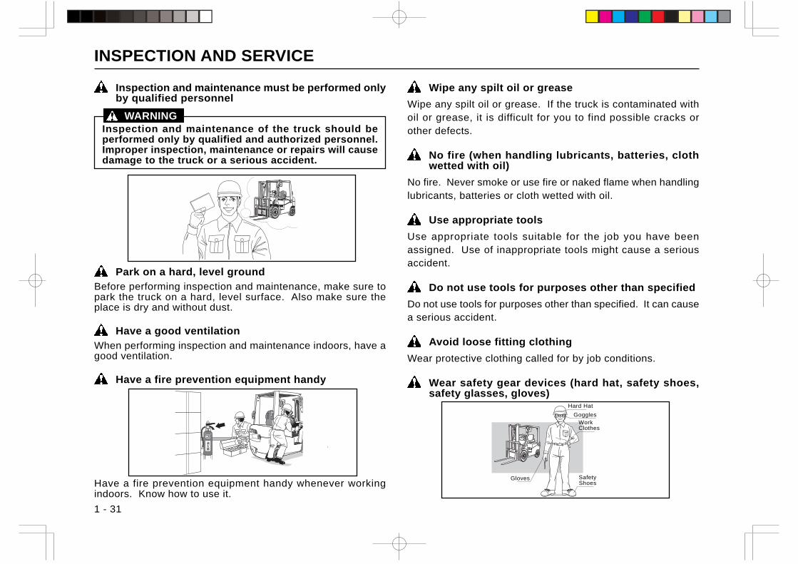
Have a fire prevention equipment handy
Have a fire prevention equipment handy whenever workingindoors. Know how to use it.
Gloves SafetyShoes
WorkClothes
Goggles
Hard Hat
WARNING
INSPECTION AND SERVICE
1 - 32
When working in a group, have a leader and followhis instructions
Make sure the forks and other attachment (if any)are on the ground
Before starting inspection, shut off the engine Engine-powered trucks
Make sure the engine is shut off before trying to start inspectionor maintenance.
Before starting inspection, turn off the key switch Electric trucks
Make sure to turn off the key switch before trying to startinspection or maintenance.
Unless otherwise specified, shut off the engine Engine-powered trucks
Unless otherwise specified, inspection or maintenance shouldbe performed with the engine shut off.
Unless otherwise specified, turn off the key switch Electric trucks
Unless otherwise specified, inspection or maintenance shouldbe performed with the key switch turned off.
Before starting inspection or maintenance, place thecontrol levers in neutral
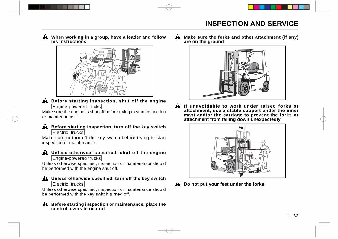
If unavoidable to work under raised forks orattachment, use a stable support under the innermast and/or the carriage to prevent the forks orattachment from falling down unexpectedly
Do not put your feet under the forks
INSPECTION AND SERVICE
1 - 33
Use caution not to get your fingers pinched in thefloor plates or hood
Be careful so as not to get your fingers caught when closingthe battery cover or doors.
Use caution not to fall down from the truck whenworking on the truck
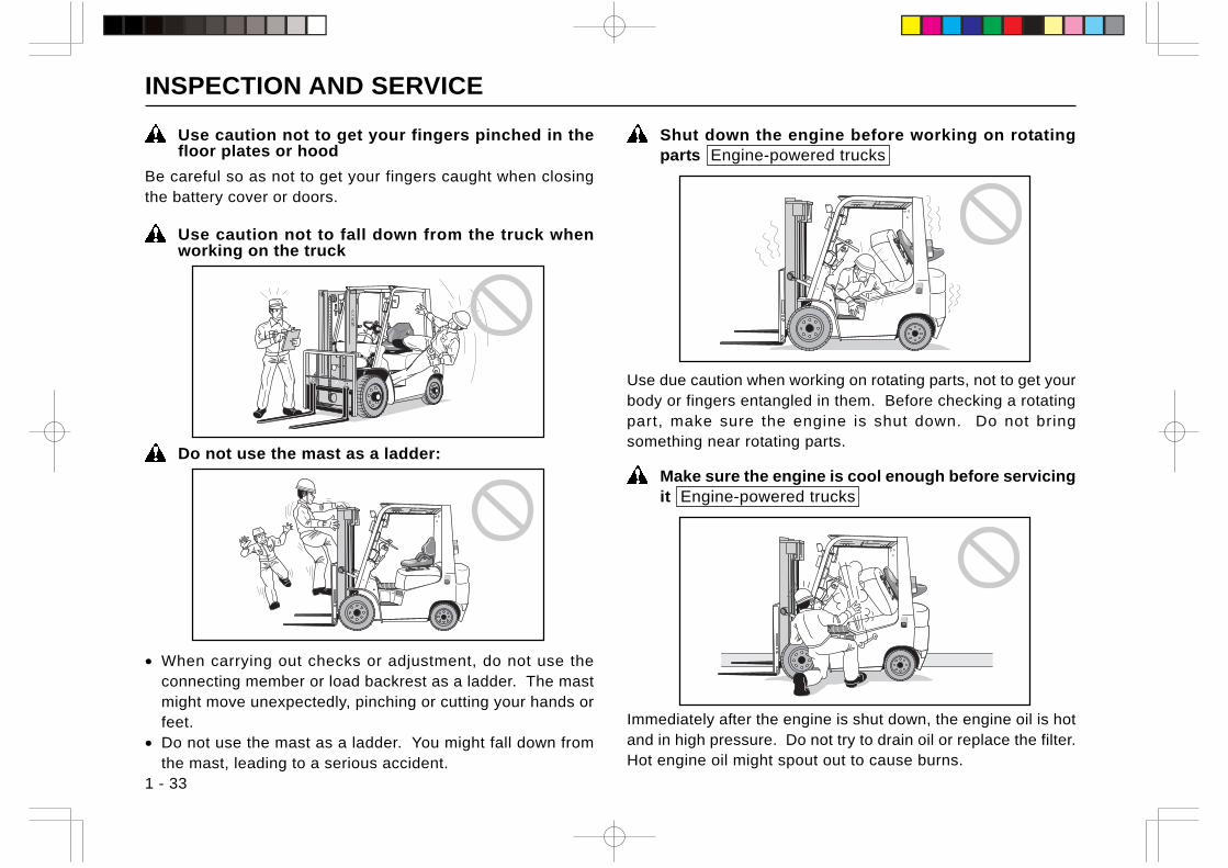
Do not use the mast as a ladder:
• When carrying out checks or adjustment, do not use theconnecting member or load backrest as a ladder. The mastmight move unexpectedly, pinching or cutting your hands orfeet.
• Do not use the mast as a ladder. You might fall down fromthe mast, leading to a serious accident.
Shut down the engine before working on rotatingparts Engine-powered trucks
Use due caution when working on rotating parts, not to get yourbody or fingers entangled in them. Before checking a rotatingpart, make sure the engine is shut down. Do not bringsomething near rotating parts.
Make sure the engine is cool enough before servicingit Engine-powered trucks
Immediately after the engine is shut down, the engine oil is hotand in high pressure. Do not try to drain oil or replace the filter.Hot engine oil might spout out to cause burns.
INSPECTION AND SERVICE
1 - 34
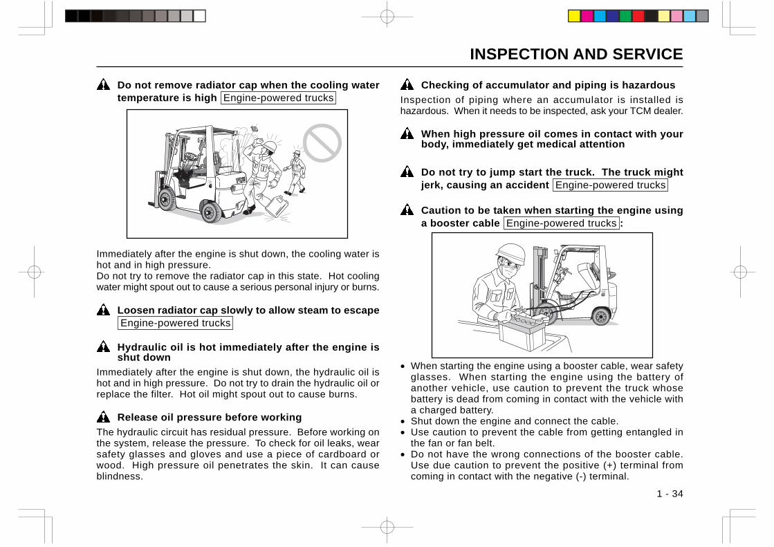
Do not remove radiator cap when the cooling watertemperature is high Engine-powered trucks
Immediately after the engine is shut down, the cooling water ishot and in high pressure.Do not try to remove the radiator cap in this state. Hot coolingwater might spout out to cause a serious personal injury or burns.
Loosen radiator cap slowly to allow steam to escape Engine-powered trucks
Hydraulic oil is hot immediately after the engine isshut down
Immediately after the engine is shut down, the hydraulic oil ishot and in high pressure. Do not try to drain the hydraulic oil orreplace the filter. Hot oil might spout out to cause burns.
Release oil pressure before working
The hydraulic circuit has residual pressure. Before working onthe system, release the pressure. To check for oil leaks, wearsafety glasses and gloves and use a piece of cardboard orwood. High pressure oil penetrates the skin. It can causeblindness.
Checking of accumulator and piping is hazardous
Inspection of piping where an accumulator is installed ishazardous. When it needs to be inspected, ask your TCM dealer.
When high pressure oil comes in contact with yourbody, immediately get medical attention
Do not try to jump start the truck. The truck mightjerk, causing an accident Engine-powered trucks
Caution to be taken when starting the engine usinga booster cable Engine-powered trucks :
• When starting the engine using a booster cable, wear safetyglasses. When starting the engine using the battery ofanother vehicle, use caution to prevent the truck whosebattery is dead from coming in contact with the vehicle witha charged battery.
• Shut down the engine and connect the cable.• Use caution to prevent the cable from getting entangled in
the fan or fan belt.• Do not have the wrong connections of the booster cable.
Use due caution to prevent the positive (+) terminal fromcoming in contact with the negative (-) terminal.
INSPECTION AND SERVICE
1 - 35
Use the specified brand of brake fluid
Use caution not to allow the entrance of dust intothe brake fluid reservoir
Use caution to keep the breather of the brake fluidreservoir cap from clogging
Handling Long Life Coolant (LLC)
Engine-powered trucksThe LLC is flammable and poisonous. When storing it, attacha label “Dangerous substance” and keep it out of reach ofchildren.• The LLC is flammable. When handling the LLC, never smoke
or use fire or naked flame near the LLC.• The LLC is poisonous. Do not swallow it. If anyone
swallowed it accidentally, let him drink a lot of water, inducevomiting and get medical attention immediately.
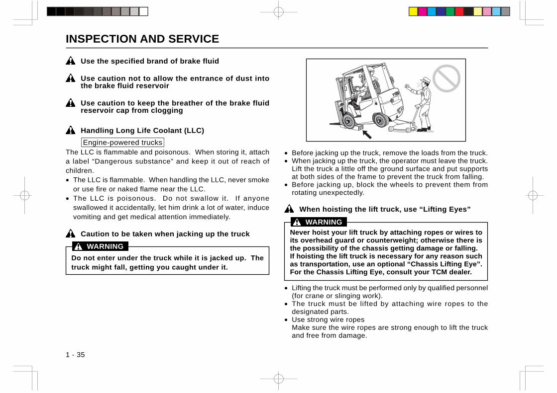
Caution to be taken when jacking up the truck
Do not enter under the truck while it is jacked up. Thetruck might fall, getting you caught under it.
• Before jacking up the truck, remove the loads from the truck.• When jacking up the truck, the operator must leave the truck.
Lift the truck a little off the ground surface and put supportsat both sides of the frame to prevent the truck from falling.
• Before jacking up, block the wheels to prevent them fromrotating unexpectedly.
When hoisting the lift truck, use “Lifting Eyes”
Never hoist your lift truck by attaching ropes or wires toits overhead guard or counterweight; otherwise there isthe possibility of the chassis getting damage or falling.If hoisting the lift truck is necessary for any reason suchas transportation, use an optional “Chassis Lifting Eye”.For the Chassis Lifting Eye, consult your TCM dealer.
• Lifting the truck must be performed only by qualified personnel(for crane or slinging work).
• The truck must be lifted by attaching wire ropes to thedesignated parts.
• Use strong wire ropesMake sure the wire ropes are strong enough to lift the truckand free from damage.
WARNING
WARNING
INSPECTION AND SERVICE
1 - 36
Cautions to be taken when handling batteries:
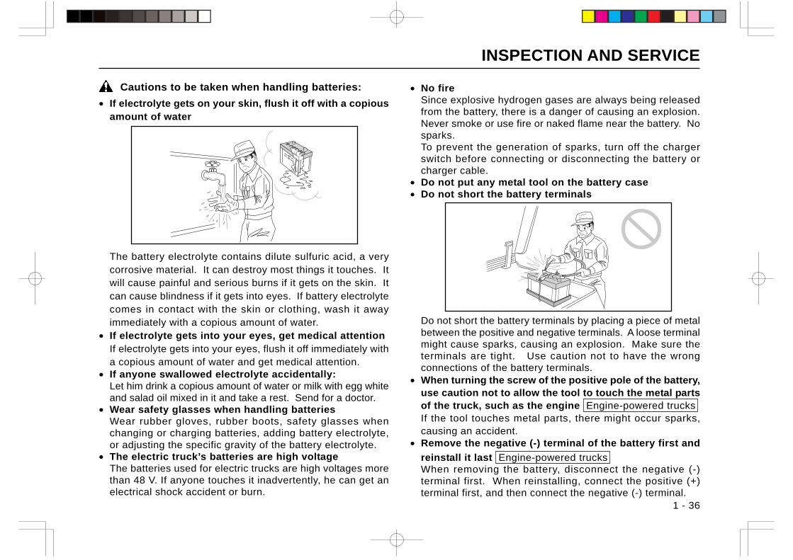
• If electrolyte gets on your skin, flush it off with a copiousamount of water
The battery electrolyte contains dilute sulfuric acid, a verycorrosive material. It can destroy most things it touches. Itwill cause painful and serious burns if it gets on the skin. Itcan cause blindness if it gets into eyes. If battery electrolytecomes in contact with the skin or clothing, wash it awayimmediately with a copious amount of water.
• If electrolyte gets into your eyes, get medical attentionIf electrolyte gets into your eyes, flush it off immediately witha copious amount of water and get medical attention.
• If anyone swallowed electrolyte accidentally:Let him drink a copious amount of water or milk with egg whiteand salad oil mixed in it and take a rest. Send for a doctor.
• Wear safety glasses when handling batteriesWear rubber gloves, rubber boots, safety glasses whenchanging or charging batteries, adding battery electrolyte,or adjusting the specific gravity of the battery electrolyte.
• The electric truck’s batteries are high voltageThe batteries used for electric trucks are high voltages morethan 48 V. If anyone touches it inadvertently, he can get anelectrical shock accident or burn.
• No fireSince explosive hydrogen gases are always being releasedfrom the battery, there is a danger of causing an explosion.Never smoke or use fire or naked flame near the battery. Nosparks.To prevent the generation of sparks, turn off the chargerswitch before connecting or disconnecting the battery orcharger cable.
• Do not put any metal tool on the battery case• Do not short the battery terminals
Do not short the battery terminals by placing a piece of metalbetween the positive and negative terminals. A loose terminalmight cause sparks, causing an explosion. Make sure theterminals are tight. Use caution not to have the wrongconnections of the battery terminals.
• When turning the screw of the positive pole of the battery,use caution not to allow the tool to touch the metal partsof the truck, such as the engine Engine-powered trucksIf the tool touches metal parts, there might occur sparks,causing an accident.
• Remove the negative (-) terminal of the battery first and
reinstall it last Engine-powered trucksWhen removing the battery, disconnect the negative (-)terminal first. When reinstalling, connect the positive (+)terminal first, and then connect the negative (-) terminal.
INSPECTION AND SERVICE
1 - 37
• When charging the battery, follow the instructions in theInstruction Manual of the charger
• No fire during chargingBatteries give off hydrogen gases during charging. No fire.No sparks.
• Make sure the battery electrolyte temperature is below40°CHydrogen gases are released from the battery duringcharging, causing the battery to heat. Before trying to chargethe battery, make sure the battery electrolyte temperature isbelow 40°C.(If the electrolyte temperature reaches 50°C or more,discont inue charging and wai t unt i l the electro lytetemperature drops to 40°C or lower.)
••••• Have a good ventilation when chargingSince hydrogen gases are released from the battery duringcharging. Have a good ventilation; otherwise an explosionmight result. Keep the battery case cover open.
• Do not connect or disconnect the battery receptacles with
the battery circuit conducting Electric trucks• When cleaning the battery, make sure the battery caps
are securely tightened
• Static electricity is hazardousStatic electricity is generated when cleaning the top surfaceor connections of the battery with a dry cloth, or covering thebattery with a vinyl sheet. It might cause an explosion.
• Static electricity from the bodyBefore checking or cleaning the battery, remove staticelectricity from your body by touching metallic parts at a placeaway from the battery.
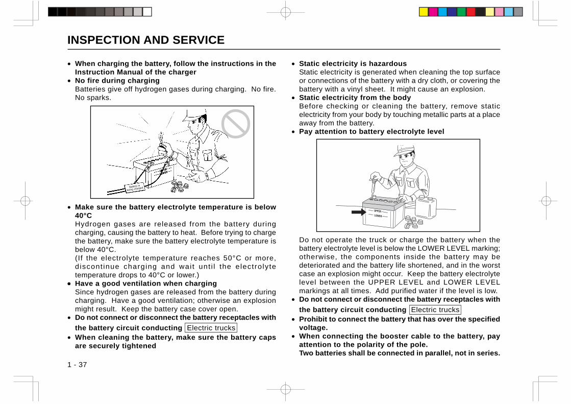
• Pay attention to battery electrolyte level
Do not operate the truck or charge the battery when thebattery electrolyte level is below the LOWER LEVEL marking;otherwise, the components inside the battery may bedeteriorated and the battery life shortened, and in the worstcase an explosion might occur. Keep the battery electrolytelevel between the UPPER LEVEL and LOWER LEVELmarkings at all times. Add purified water if the level is low.
• Do not connect or disconnect the battery receptacles with
the battery circuit conducting Electric trucks• Prohibit to connect the battery that has over the specified
voltage.• When connecting the booster cable to the battery, pay
attention to the polarity of the pole.Two batteries shall be connected in parallel, not in series.
Battery is
being charged
INSPECTION AND SERVICE
1 - 38
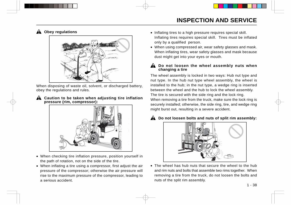
Obey regulations
When disposing of waste oil, solvent, or discharged battery,obey the regulations and rules.
Caution to be taken when adjusting tire inflationpressure (rim, compressor):
• When checking tire inflation pressure, position yourself inthe path of rotation, not on the side of the tire.
• When inflating a tire using a compressor, first adjust the airpressure of the compressor; otherwise the air pressure willrise to the maximum pressure of the compressor, leading toa serious accident.
• Inflating tires to a high pressure requires special skill.Inflating tires requires special skill. Tires must be inflatedonly by a qualified person.
• When using compressed air, wear safety glasses and mask.When inflating tires, wear safety glasses and mask becausedust might get into your eyes or mouth.
Do not loosen the wheel assembly nuts whenchanging a tire
The wheel assembly is locked in two ways: Hub nut type andnut type. In the hub nut type wheel assembly, the wheel isinstalled to the hub; in the nut type, a wedge ring is insertedbetween the wheel and the hub to lock the wheel assembly.The tire is secured with the side ring and the lock ring.When removing a tire from the truck, make sure the lock ring issecurely installed; otherwise, the side ring, tire, and wedge ringmight burst out, resulting in a severe accident.
Do not loosen bolts and nuts of split rim assembly:
• The wheel has hub nuts that secure the wheel to the huband rim nuts and bolts that assemble two rims together. Whenremoving a tire from the truck, do not loosen the bolts andnuts of the split rim assembly.
INSPECTION AND SERVICE
1 - 39
If the bolts and nuts of the split rim assembly are removed,the rims, bolts or nuts might blow off due to the internalpressure of the tire, to cause a serious personal injury.
• When replacing the rim assembly, install a new rim assemblywith the head of each of the dowel bolts of the rim assemblypointing outside. (This helps make it difficult to loosen therim bolts with the tire attached to the truck. Some bolts havea special shape for this purpose.)
• After replacing tires, test run the truck to check to see if thehub nuts are securely tightened. If a loose hub nut is found,tighten it to the specified torque.
Leave the disassembly and reassembly of tires, tubesand rims to a specialist
The inflation pressure of tires of the lift truck is very high (about700 - 1,000 kPa) and thus due caution must be required todisassemble or reassemble the t i res. An improperlyreassembled tire might cause explosion to let parts fly intopieces, resulting in a serious personal injury.
Keep the tension of the right and left chains even
Uneven tension of the right and left chains means uneven loadseven if they are properly placed on the forks. It may also leadto broken chains.
Keep sideview mirrors, backup alarm, and lamps ingood working condition
Adjust the sideview mirrors to gain a full rear vision and keepthe mirror’s surface clean (if so equipped). The backup buzzershould sound when the direction change lever is placed in thereverse position. If the buzzer fails to sound, have it repaired.
Make sure the lamps turn on and off properly. Burned-out bulbsmust be replaced with new ones.
Avoid fire hazards
• Wipe away any spilt lubricant or fuel inside the engine room.• Do not leave waste cloth or paper contaminated with fuel or
lubricant inside the engine room; it can cause fire hazards.• The exhaust pipe, muffler and exhaust manifold are hot
immediately after the engine has been shut off or while theengine is running.
INSPECTION AND SERVICE
1 - 40
CARBON MONOXIDE POISONING
Engine-powered trucksThe following carbon monoxide control to avoid itspoisoning is the user’s responsibility.
Characteristics of carbon monoxideThe exhaust from all internal combustion engines containcarbon monoxide, a colorless, odorless, tasteless, poisonousgas. Exposure to carbon monoxide can cause serious injury orhealth problems, including death.• Places where carbon monoxide gas concentrated
Carbon monoxide can become concentrated in areas suchas trailers, containers, coolers, freezers, and poorly ventilatedrooms or buildings. Therefore, limit internal combustionengine usage in those areas.
• Symptoms of carbon monoxide exposureCommon symptoms of carbon monoxide exposure mayinclude headache, dizziness, and nausea. The smell ofinternal combustion engine exhaust means carbon monoxidecould be present.
• Treatment for carbon monoxide gas poisoningIf an operator experiences these symptoms, move him intofresh air, seek medical attention as required, and contact youremployer so he can monitor threshold l imit values.(Consideration should be given to shutting off the operator’sinternal combustion engine.)
Control of noxious gases and fumes• Source of carbon monoxide gas
Carbon monoxide is the product of incomplete burning of anymaterial containing carbon, such as gasoline, LP and natural
gas, and diesel fuel. Internal combustion engines that usethese fuels are sources of exposure in the workplace.
• Control of carbon monoxide gasControl of carbon monoxide levels in the workplace isdependent on ventilation and proper maintenance of carbonmonoxide producers including internal combustion-poweredequipment. See periodical maintenance of this manual.Properly running internal combustion engines will still producecarbon monoxide emissions.
• VentilationVentilation shall be provided in enclosed areas where internalcombustion-powered equipment is used to maintain anatmosphere that shall not exceed the contamination levelsspecified by the American Conference of GovernmentalIndustrial Hygienists Threshold Limit Values of AirborneContaminants.
CAUTION PLATES
1 - 41
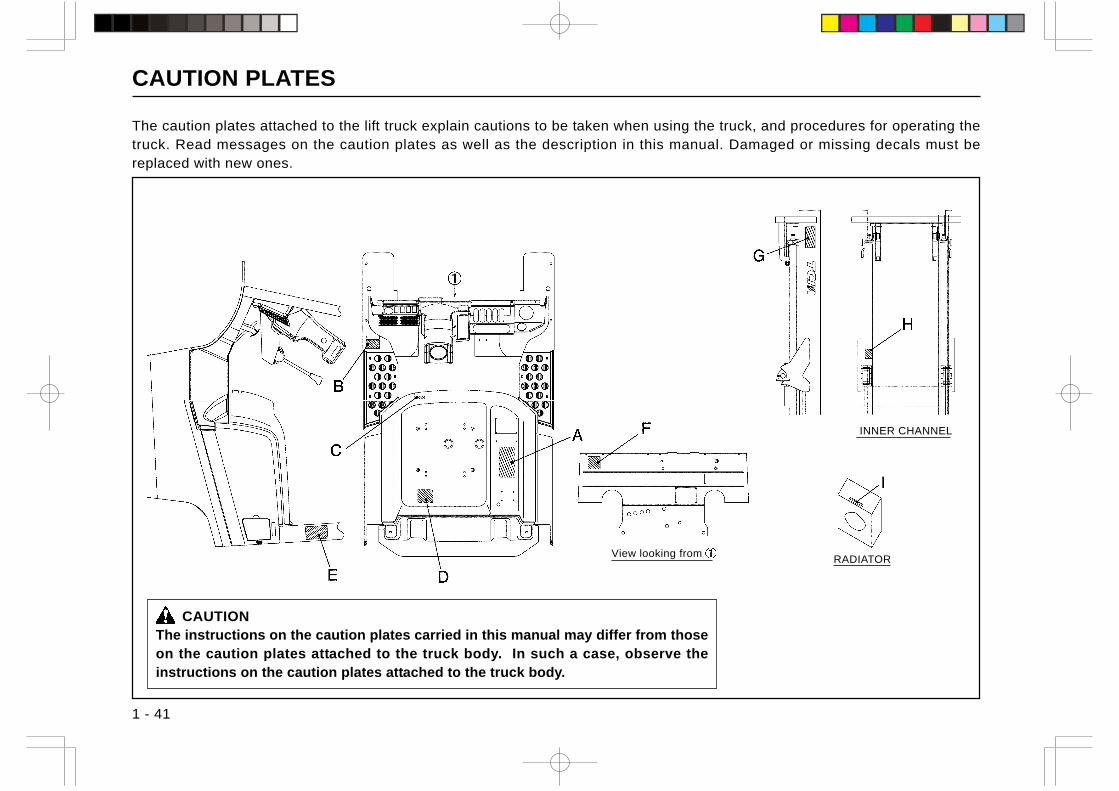
The caution plates attached to the lift truck explain cautions to be taken when using the truck, and procedures for operating thetruck. Read messages on the caution plates as well as the description in this manual. Damaged or missing decals must bereplaced with new ones.
CAUTIONThe instructions on the caution plates carried in this manual may differ from thoseon the caution plates attached to the truck body. In such a case, observe theinstructions on the caution plates attached to the truck body.
View looking from RADIATOR
INNER CHANNEL
CAUTION PLATES
1 - 42
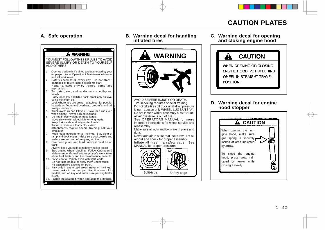
A. Safe operation
AVOID SEVERE INJURY OR DEATH.Tire servicing requires special training.Do not take tires off truck until all air pressureis out. Loosen only WHEEL LUG NUTS “A”.Do not loosen wheel assembly nuts “B” untilall air pressure is out of tire.See OPERATORS MANUAL for moreimportant instructions for wheel service andreassembly.Make sure all nuts and bolts are in place andtight.Never add air to a tire that looks low. Let allair out and check for proper assembly.Inflate all tires in a safety cage. SeeMANUAL for proper pressures.
When opening the en-gine hood, make suregas spring is securelylocked at area indicatedby arrow.
To close the enginehood, press area indi-cated by arrow whileclosing it slowly.
B. Warning decal for handlinginflated tires
WARNING
Split-type Safety cage
Air
C. Warning decal for openingand closing engine hood
D. Warning decal for enginehood stopper
CAUTION
YOU MUST FOLLOW THESE RULES TO AVOIDSEVERE INJURY OR DEATH TO YOURSELFAND OTHERS.
1. Operate truck only if trained and authorized by youremployer. Know Operation & Maintenance Manualand all work rules.
2. Safety check truck every day. Do not start ifdamaged or faulty; stop if problems start.Repair allowed only by trained, authorizedmechanics.
3. Turn, start, stop, and handle loads smoothly andslowly.Carry loads low and tilted back; stack only on levelusing minimum tilt.
4. Look where you are going. Watch out for people,hazards on floors and overhead, drop-offs and tailswing clearance.
5. Truck overturn can kill you. Slow for turns evenwhen empty. Never turn on inclines.
6. Do not lift overweight or loose loads.Move slowly with wide, high, or long loads.Keep forks wide and fully under loads.Travel in reverse if loads block view.Attachments require special training, ask youremployer.
7. Keep loads upgrade on all inclines. Stay clear oframp and dock edges. Make sure dockboards andtrailers are secure before going on them.
8. Overhead guard and load backrest must be ontruck.Always keep yourself completely inside guard.
9. Stop engine when refueling. Follow Operation &Maintenance Manual and employer’s work rulesabout fuel, battery and tire maintenance hazards.
10. Forks can fall rapidly even with light loads.Do not raise people or allow them under forks.No passengers allowed on truck.
11. Park only in authorized areas, never on inclines.Lower forks to bottom, put direction control inneutral, turn off key and make sure parking brakeis set.
12. Fasten the seat belt, when operating the lift truck.
CAUTION PLATES
1 - 43
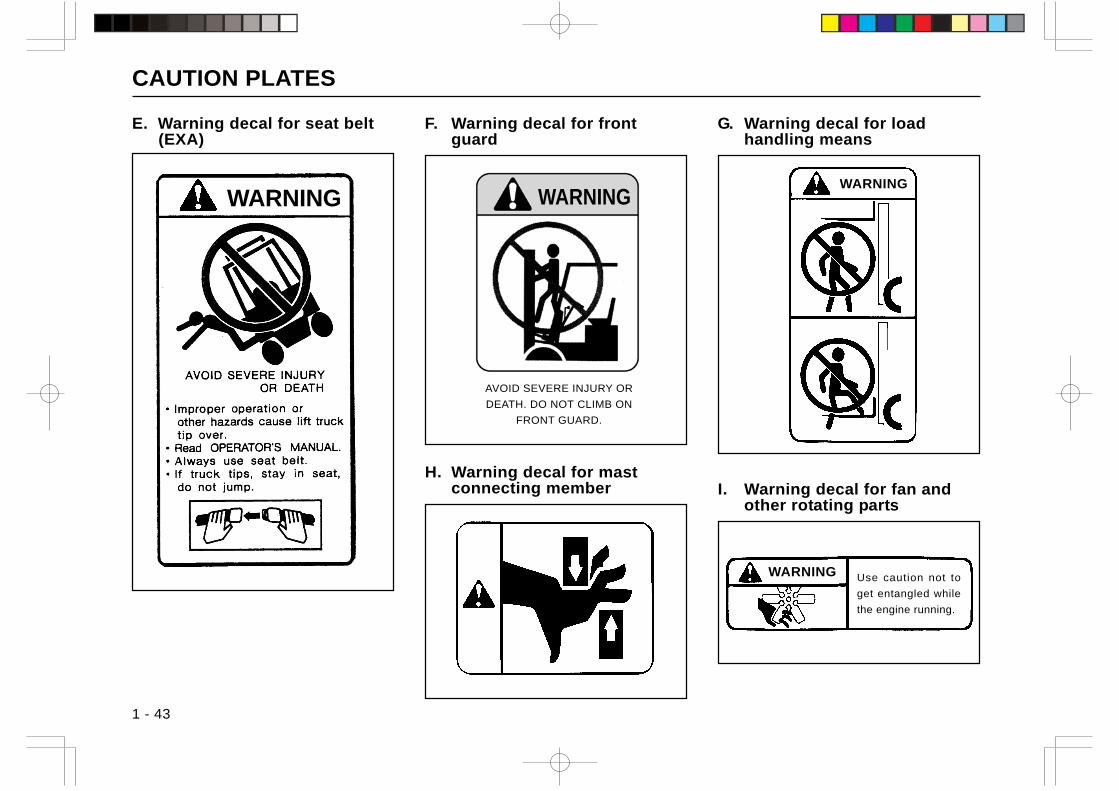
I. Warning decal for fan andother rotating parts
G. Warning decal for loadhandling means
E. Warning decal for seat belt(EXA)
F. Warning decal for frontguard
H. Warning decal for mastconnecting member
WARNING
AVOID SEVERE INJURY OR
DEATH. DO NOT CLIMB ON
FRONT GUARD.
WARNINGWARNING
Use caution not to
get entangled while
the engine running.
WARNING
CAUTION PLATES
1 - 44
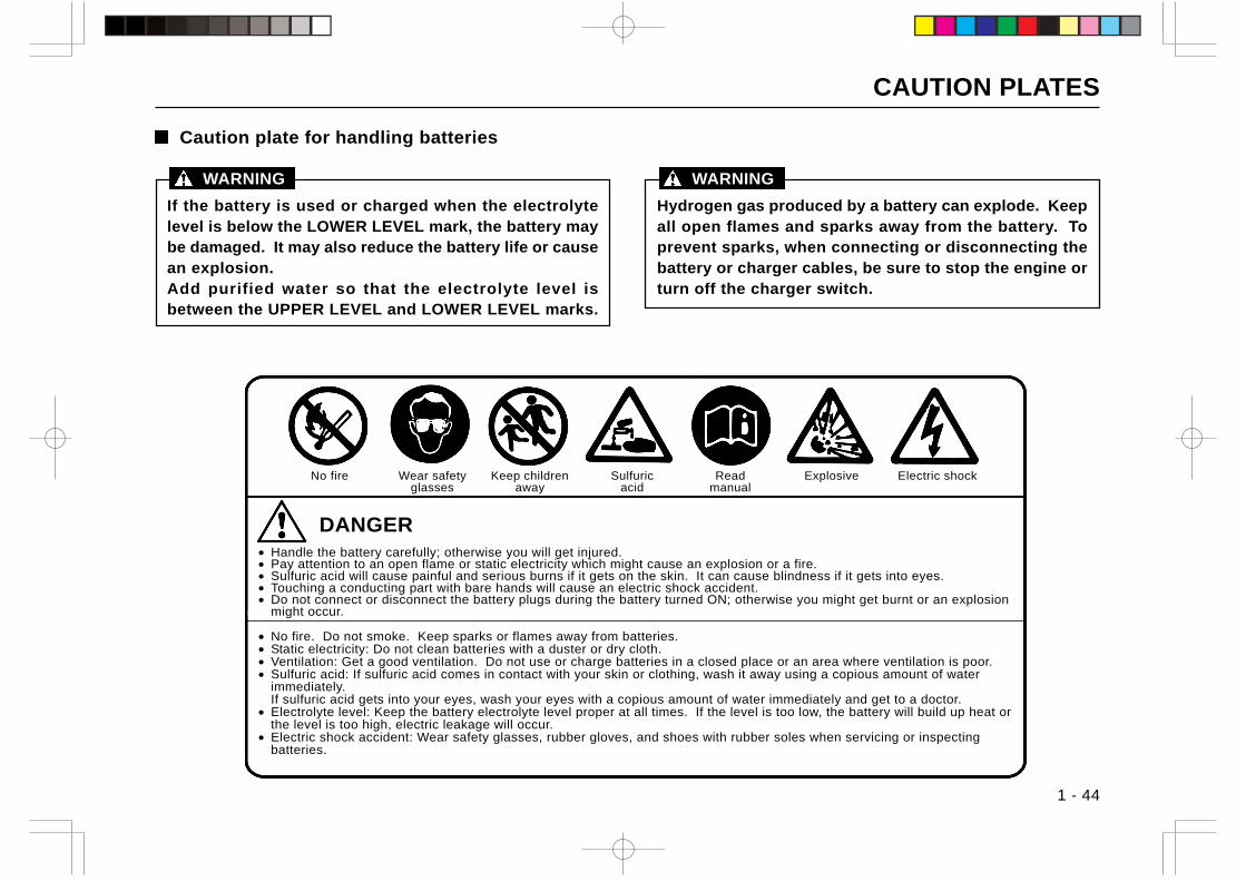
Caution plate for handling batteries
If the battery is used or charged when the electrolytelevel is below the LOWER LEVEL mark, the battery maybe damaged. It may also reduce the battery life or causean explosion.Add purified water so that the electrolyte level isbetween the UPPER LEVEL and LOWER LEVEL marks.
WARNING
Hydrogen gas produced by a battery can explode. Keepall open flames and sparks away from the battery. Toprevent sparks, when connecting or disconnecting thebattery or charger cables, be sure to stop the engine orturn off the charger switch.
WARNING
Electric shock
DANGER• Handle the battery carefully; otherwise you will get injured.• Pay attention to an open flame or static electricity which might cause an explosion or a fire.• Sulfuric acid will cause painful and serious burns if it gets on the skin. It can cause blindness if it gets into eyes.• Touching a conducting part with bare hands will cause an electric shock accident.• Do not connect or disconnect the battery plugs during the battery turned ON; otherwise you might get burnt or an explosion
might occur.
• No fire. Do not smoke. Keep sparks or flames away from batteries.• Static electricity: Do not clean batteries with a duster or dry cloth.• Ventilation: Get a good ventilation. Do not use or charge batteries in a closed place or an area where ventilation is poor.• Sulfuric acid: If sulfuric acid comes in contact with your skin or clothing, wash it away using a copious amount of water
immediately.If sulfuric acid gets into your eyes, wash your eyes with a copious amount of water immediately and get to a doctor.
• Electrolyte level: Keep the battery electrolyte level proper at all times. If the level is too low, the battery will build up heat orthe level is too high, electric leakage will occur.
• Electric shock accident: Wear safety glasses, rubber gloves, and shoes with rubber soles when servicing or inspectingbatteries.
No fire Wear safetyglasses
Keep childrenaway
Sulfuricacid
Readmanual
Explosive

MEMO
dJ E ・E ・E ・.-=!I I I I ベト l - ・E ・E ・. I I ・・ |二
十 十
1-¥ ベト ¥-F
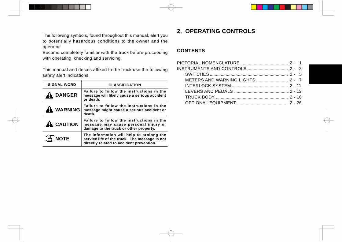
2. OPERATING CONTROLS
CONTENTS
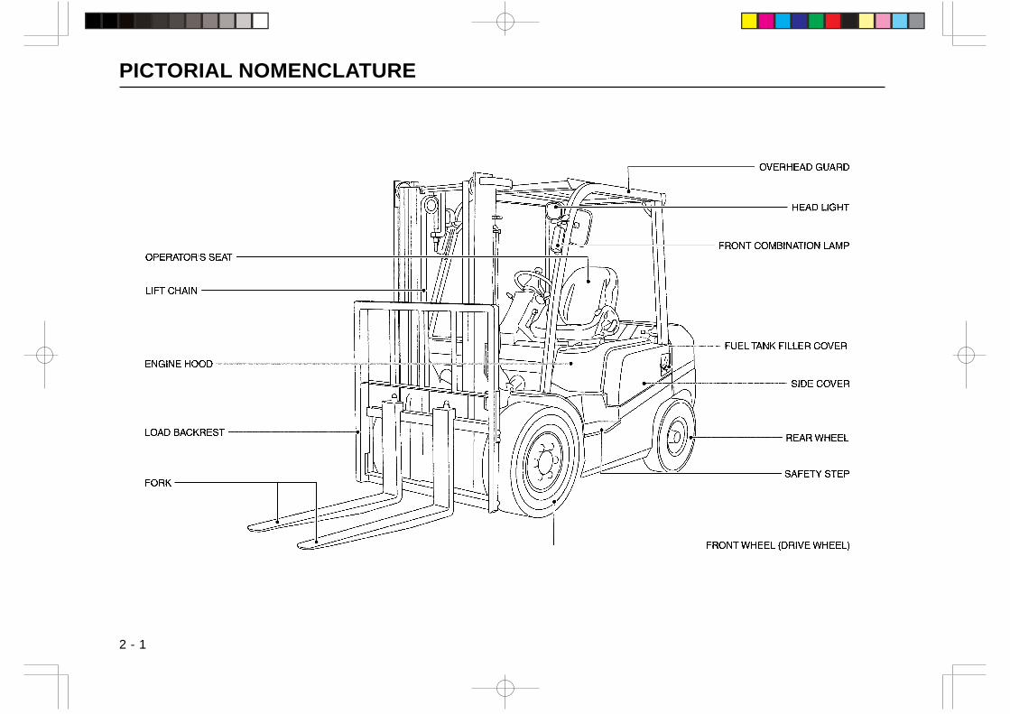
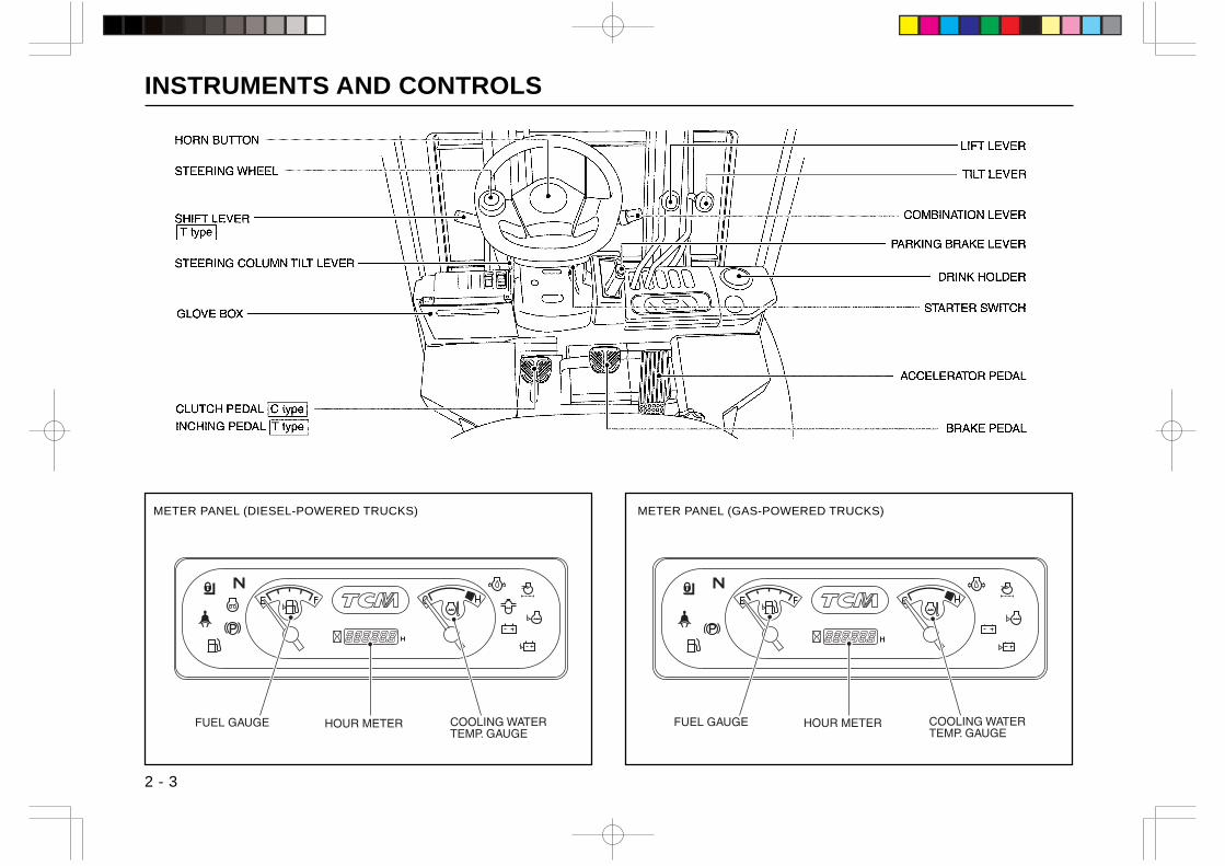
PICTORIAL NOMENCLATURE ....................................... 2 - 1INSTRUMENTS AND CONTROLS ................................. 2 - 3
SWITCHES ................................................................ 2 - 5METERS AND WARNING LIGHTS .......................... 2 - 7INTERLOCK SYSTEM .............................................. 2 - 11LEVERS AND PEDALS ............................................ 2 - 12TRUCK BODY ........................................................... 2 - 16OPTIONAL EQUIPMENT .......................................... 2 - 26
The following symbols, found throughout this manual, alert youto potentially hazardous conditions to the owner and theoperator.Become completely familiar with the truck before proceedingwith operating, checking and servicing.
This manual and decals affixed to the truck use the followingsafety alert indications.
SIGNAL WORD CLASSIFICATION
Failure to follow the instructions in themessage will likely cause a serious accidentor death.
Failure to follow the instructions in themessage might cause a serious accident ordeath.
Failure to follow the instructions in themessage may cause personal injury ordamage to the truck or other property.
The information will help to prolong theservice life of the truck. The message is notdirectly related to accident prevention.
DANGER
WARNING
CAUTION
NOTE
PICTORIAL NOMENCLATURE
2 - 1
」
OPERATOR'S SEAT
LlFTCHAIN
ENGINE HOOD
LOAD BACKREST
~
fh v
fh y
| ・・・・・・・・I I 圃
OVERHEAD GUARD
HEAD LlGHT
FRONT COMBINATION LAMP
FRONT WHEEL (DRIVE WHEEし)
L
n==

PICTORIAL NOMENCLATURE
2 - 2
」
REAR COMBINATION LAMP
SIDEVIEW MIRROR
OPERATOR'S SEAT
COUNTERWEIGHT
DRAWBAR
~
fh v
fh y
| ・・・・・・・・I I 圃
OVERHEAD GUARD
HANDGRIP
L
n==
INSTRUMENTS AND CONTROLS
2 - 3
METER PANEL (DIESEL-POWERED TRUCKS) METER PANEL (GAS-POWERED TRUCKS)
INSTRUMENTS AND CONTROLS
2 - 4
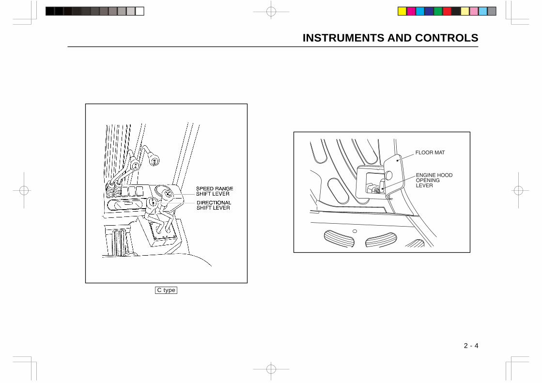
C type
」
~
仁二コ
fh v
fh y
| ・・・・・・・・I I 圃 L
ミミ306喜多
n==
INSTRUMENTS AND CONTROLS
2 - 5
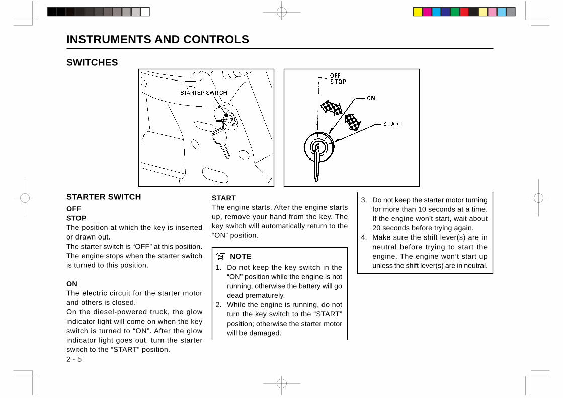
STARTER SWITCH
OFFSTOPThe position at which the key is insertedor drawn out.The starter switch is “OFF” at this position.The engine stops when the starter switchis turned to this position.
ONThe electric circuit for the starter motorand others is closed.On the diesel-powered truck, the glowindicator light will come on when the keyswitch is turned to “ON”. After the glowindicator light goes out, turn the starterswitch to the “START” position.
SWITCHES
STARTThe engine starts. After the engine startsup, remove your hand from the key. Thekey switch will automatically return to the“ON” position.
NOTE
1. Do not keep the key switch in the“ON” position while the engine is notrunning; otherwise the battery will godead prematurely.
2. While the engine is running, do notturn the key switch to the “START”position; otherwise the starter motorwill be damaged.
3. Do not keep the starter motor turningfor more than 10 seconds at a time.If the engine won’t start, wait about20 seconds before trying again.
4. Make sure the shift lever(s) are inneutral before trying to start theengine. The engine won’t start upunless the shift lever(s) are in neutral.
INSTRUMENTS AND CONTROLS
2 - 6
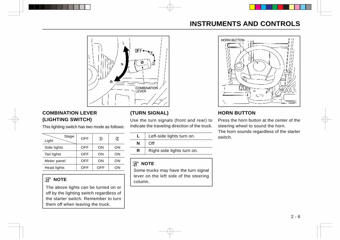
COMBINATION LEVER(LIGHTING SWITCH)
This lighting switch has two mode as follows:
StageOFF
Light
Side lights OFF ON ON
Tail lights OFF ON ON
Meter panel OFF ON ON
Head lights OFF OFF ON
NOTE
The above lights can be turned on oroff by the lighting switch regardless ofthe starter switch. Remember to turnthem off when leaving the truck.
HORN BUTTON
Press the horn button at the center of thesteering wheel to sound the horn.The horn sounds regardless of the starterswitch.
(TURN SIGNAL)
Use the turn signals (front and rear) toindicate the traveling direction of the truck.
L Left-side lights turn on.
N Off
R Right-side lights turn on.
NOTE
Some trucks may have the turn signallever on the left side of the steeringcolumn.
INSTRUMENTS AND CONTROLS
2 - 7
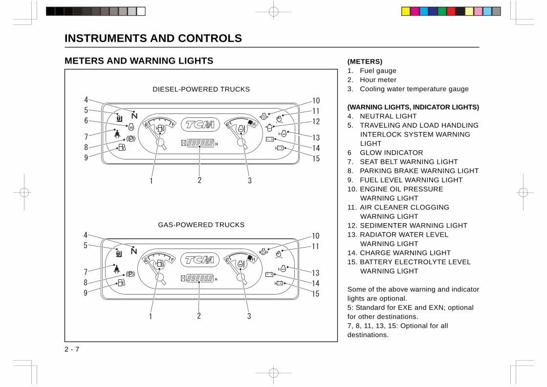
(METERS)1. Fuel gauge2. Hour meter3. Cooling water temperature gauge
(WARNING LIGHTS, INDICATOR LIGHTS)4. NEUTRAL LIGHT5. TRAVELING AND LOAD HANDLING
INTERLOCK SYSTEM WARNINGLIGHT
6 GLOW INDICATOR7. SEAT BELT WARNING LIGHT8. PARKING BRAKE WARNING LIGHT9. FUEL LEVEL WARNING LIGHT10. ENGINE OIL PRESSURE
WARNING LIGHT11. AIR CLEANER CLOGGING
WARNING LIGHT12. SEDIMENTER WARNING LIGHT13. RADIATOR WATER LEVEL
WARNING LIGHT14. CHARGE WARNING LIGHT15. BATTERY ELECTROLYTE LEVEL
WARNING LIGHT
Some of the above warning and indicatorlights are optional.5: Standard for EXE and EXN; optionalfor other destinations.7, 8, 11, 13, 15: Optional for alldestinations.
METERS AND WARNING LIGHTS
DIESEL-POWERED TRUCKS
GAS-POWERED TRUCKS
INSTRUMENTS AND CONTROLS
2 - 8
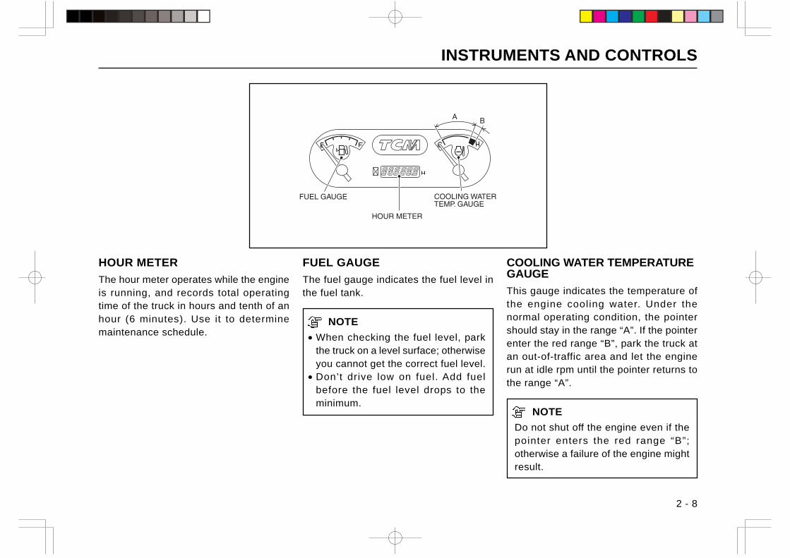
HOUR METER
The hour meter operates while the engineis running, and records total operatingtime of the truck in hours and tenth of anhour (6 minutes). Use it to determinemaintenance schedule.
COOLING WATER TEMPERATUREGAUGE
This gauge indicates the temperature ofthe engine cooling water. Under thenormal operating condition, the pointershould stay in the range “A”. If the pointerenter the red range “B”, park the truck atan out-of-traffic area and let the enginerun at idle rpm until the pointer returns tothe range “A”.
NOTE
Do not shut off the engine even if thepointer enters the red range “B”;otherwise a failure of the engine mightresult.
FUEL GAUGE
The fuel gauge indicates the fuel level inthe fuel tank.
NOTE
• When checking the fuel level, parkthe truck on a level surface; otherwiseyou cannot get the correct fuel level.
• Don’t drive low on fuel. Add fuelbefore the fuel level drops to theminimum.
INSTRUMENTS AND CONTROLS
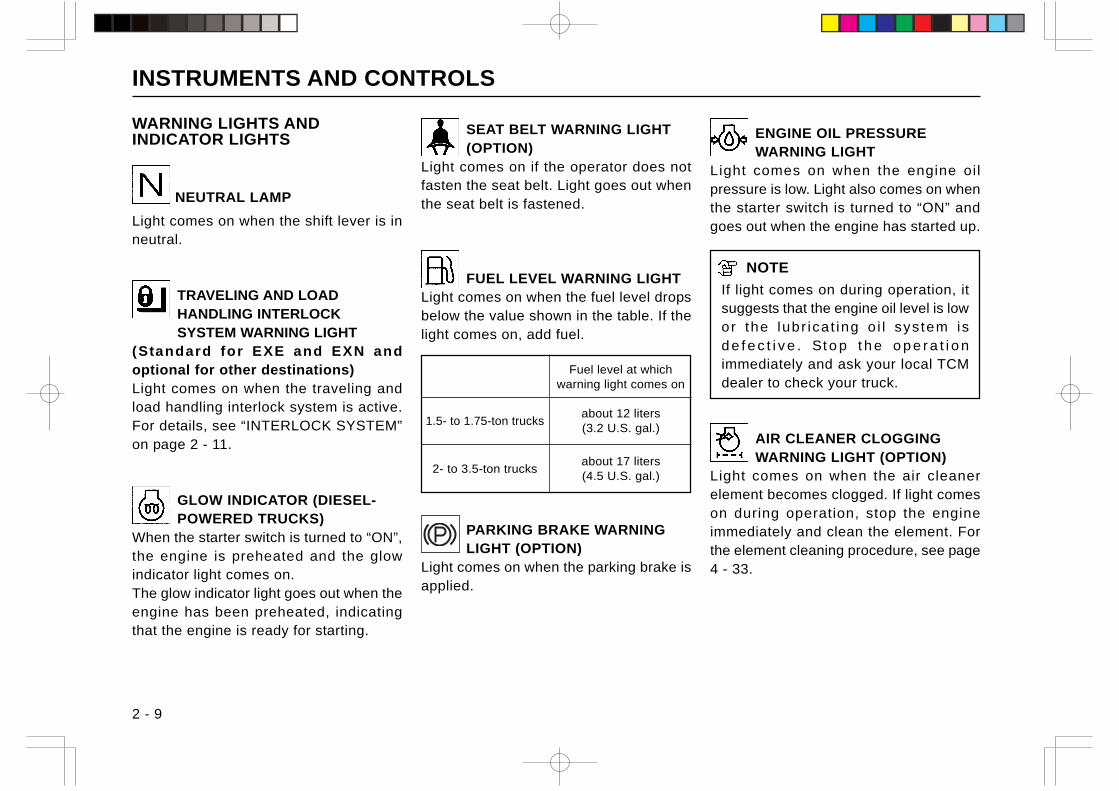
WARNING LIGHTS ANDINDICATOR LIGHTS
NEUTRAL LAMP
Light comes on when the shift lever is inneutral.
TRAVELING AND LOADHANDLING INTERLOCKSYSTEM WARNING LIGHT
(Standard for EXE and EXN andoptional for other destinations)Light comes on when the traveling andload handling interlock system is active.For details, see “INTERLOCK SYSTEM”on page 2 - 11.
GLOW INDICATOR (DIESEL-POWERED TRUCKS)
When the starter switch is turned to “ON”,the engine is preheated and the glowindicator light comes on.The glow indicator light goes out when theengine has been preheated, indicatingthat the engine is ready for starting.
2 - 9
SEAT BELT WARNING LIGHT(OPTION)
Light comes on if the operator does notfasten the seat belt. Light goes out whenthe seat belt is fastened.
FUEL LEVEL WARNING LIGHTLight comes on when the fuel level dropsbelow the value shown in the table. If thelight comes on, add fuel.
Fuel level at whichwarning light comes on
1.5- to 1.75-ton trucksabout 12 liters(3.2 U.S. gal.)
2- to 3.5-ton trucksabout 17 liters(4.5 U.S. gal.)
PARKING BRAKE WARNINGLIGHT (OPTION)
Light comes on when the parking brake isapplied.
ENGINE OIL PRESSUREWARNING LIGHT
Light comes on when the engine oilpressure is low. Light also comes on whenthe starter switch is turned to “ON” andgoes out when the engine has started up.
NOTE
If light comes on during operation, itsuggests that the engine oil level is lowor the lubr icat ing o i l sys tem isd e f e c t i v e . St o p t h e o p e r a t i o nimmediately and ask your local TCMdealer to check your truck.
AIR CLEANER CLOGGINGWARNING LIGHT (OPTION)
Light comes on when the air cleanerelement becomes clogged. If light comeson during operation, stop the engineimmediately and clean the element. Forthe element cleaning procedure, see page4 - 33.
INSTRUMENTS AND CONTROLS
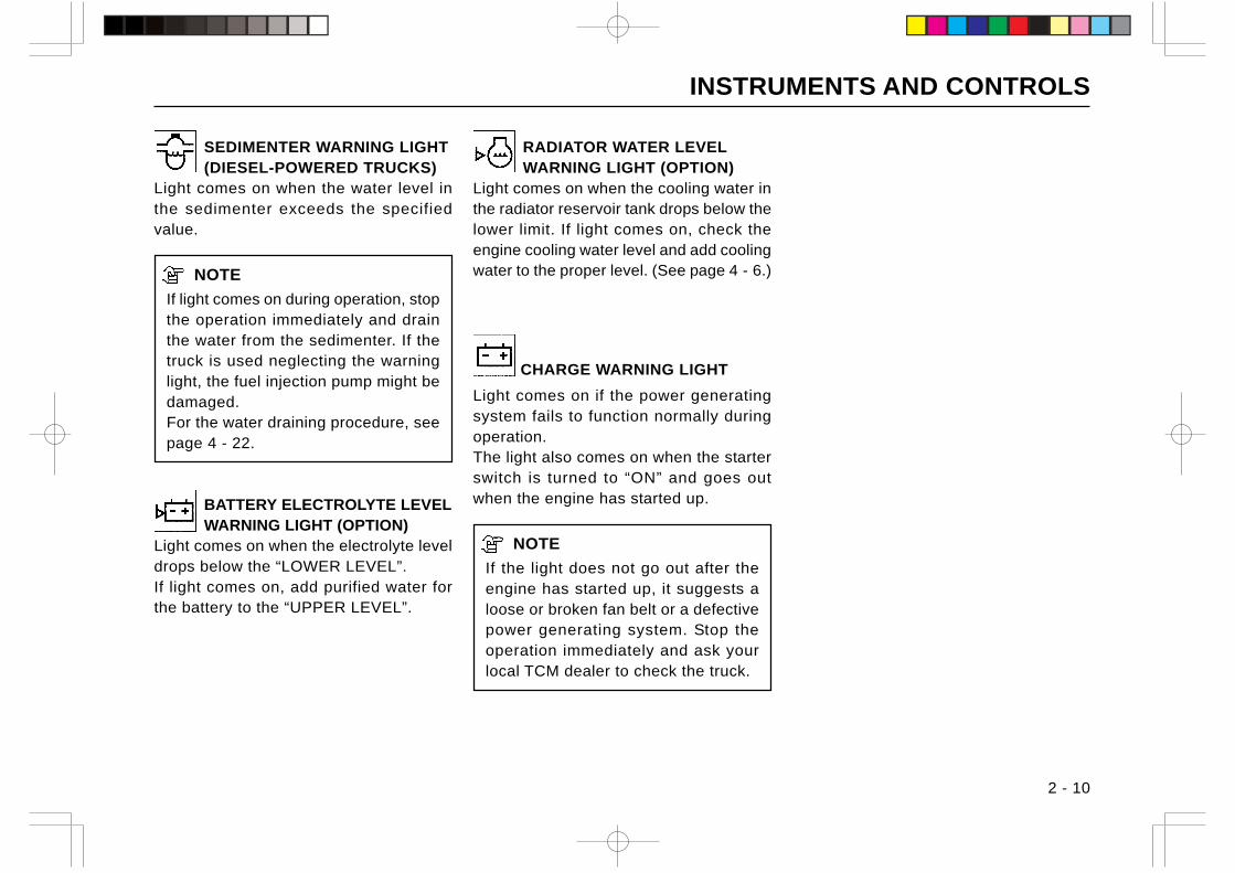
SEDIMENTER WARNING LIGHT(DIESEL-POWERED TRUCKS)
Light comes on when the water level inthe sedimenter exceeds the specifiedvalue.
NOTE
If light comes on during operation, stopthe operation immediately and drainthe water from the sedimenter. If thetruck is used neglecting the warninglight, the fuel injection pump might bedamaged.For the water draining procedure, seepage 4 - 22.
BATTERY ELECTROLYTE LEVELWARNING LIGHT (OPTION)
Light comes on when the electrolyte leveldrops below the “LOWER LEVEL”.If light comes on, add purified water forthe battery to the “UPPER LEVEL”.
RADIATOR WATER LEVELWARNING LIGHT (OPTION)
Light comes on when the cooling water inthe radiator reservoir tank drops below thelower limit. If light comes on, check theengine cooling water level and add coolingwater to the proper level. (See page 4 - 6.)
CHARGE WARNING LIGHT
Light comes on if the power generatingsystem fails to function normally duringoperation.The light also comes on when the starterswitch is turned to “ON” and goes outwhen the engine has started up.
NOTE
If the light does not go out after theengine has started up, it suggests aloose or broken fan belt or a defectivepower generating system. Stop theoperation immediately and ask yourlocal TCM dealer to check the truck.
2 - 10
INSTRUMENTS AND CONTROLS
2 - 11
INTERLOCK SYSTEM
TRAVELING AND LOAD HANDLING INTERLOCKSYSTEM(Standard for EXE and EXN; optional for otherdestinations)
The traveling and load handling interlock system is a safety devicefor lift trucks.When the operator gets out of the seat, the system turns on aswitch that shifts the transmission into neutral and blocks thehydraulic circuit (for lift and tilt). This system helps prevent anaccident from happening if the operator of the truck is not in thedriving position or a control is moved unintentionally when he isnot in the operator’s seat.
Interlock operation• A buzzer sounds if the operator leaves his seat while the starter
switch is on. After about 3 seconds, the transmission is lockedin neutral and the hydraulic circuit is blocked (i.e., the truckwon’t move nor the load handling system won’t operate withoutan operator in the seat even if the shift lever or any load handlinglever is operated). The warning light comes on.(If the operator returns to the operator’s seat within 3 seconds,the buzzer stops and it is possible to start the truck and operatethe load handling system as usual.)
• The buzzer also sounds and the lifting operation is locked off ifthe operator leaves his seat without applying the parking brakewhen the starter switch is off. (Note that this function is alsoavailable on clutch type trucks.)
Releasing interlocks• Releasing traveling interlock
When the operator gets in the operator’s seat and shifts theshift lever to neutral, the traveling interlock is released, thebuzzer stops, and the warning light goes out.
• Releasing load handling interlockWhen the operator gets in the operator’s seat and places allthe load handling levers in neutral, the load handling interlockis released, the buzzer stops and the warning light goes out.
Note:• The buzzer will not sound when the interlock is activated, if the
parking brake is in operation.• The traveling interlock is only available on torque converter type
trucks.• The traveling interlock only shifts the transmission to neutral; it
doesn’t engage the brakes.• If, while the truck is going up a ramp for loading onto a trailer
truck, the operator leaves the seat or rises up from the seat, oroperates the truck from a position that does not press bodyweight on the seat, the traveling interlock is activated, thetransmission is shifted to neutral, and the truck will roll back.
• Fasten the seat belt. Don’t leave or rises up from the operator’sseat while traveling.
• Don’t rest something on the operator’s seat; otherwise thetraveling interlock may fail to operate as it should.
• If the operator’s seat is replaced with a new one, use a genuineTCM operator’s seat equipped with a seat switch.
• If the operator gets in the seat with the engine not running, andturns the starter switch to “ON”, the forks can be lowered in thesame manner as usual.
• The attachment lever(s) are not provided with interlock function.
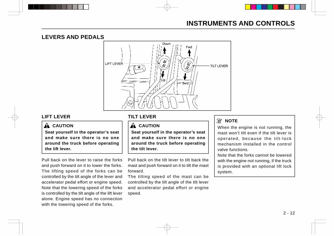
INSTRUMENTS AND CONTROLS
2 - 12
LIFT LEVER
CAUTION
Seat yourself in the operator’s seatand make sure there is no onearound the truck before operatingthe lift lever.
Pull back on the lever to raise the forksand push forward on it to lower the forks.The lifting speed of the forks can becontrolled by the tilt angle of the lever andaccelerator pedal effort or engine speed.Note that the lowering speed of the forksis controlled by the tilt angle of the lift leveralone. Engine speed has no connectionwith the lowering speed of the forks.
LEVERS AND PEDALS
NOTE
When the engine is not running, themast won’t tilt even if the tilt lever isopera ted, because the t i l t - lockmechanism installed in the controlvalve functions.Note that the forks cannot be loweredwith the engine not running, if the truckis provided with an optional lift locksystem.
TILT LEVER
CAUTION
Seat yourself in the operator’s seatand make sure there is no onearound the truck before operatingthe tilt lever.
Pull back on the tilt lever to tilt back themast and push forward on it to tilt the mastforward.The tilt ing speed of the mast can becontrolled by the tilt angle of the tilt leverand accelerator pedal effort or enginespeed.
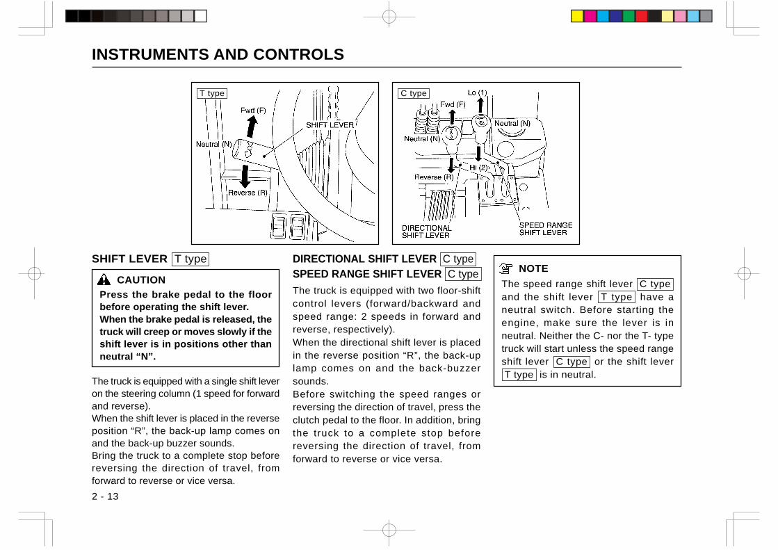
INSTRUMENTS AND CONTROLS
2 - 13
SHIFT LEVER T type
CAUTION
Press the brake pedal to the floorbefore operating the shift lever.When the brake pedal is released, thetruck will creep or moves slowly if theshift lever is in positions other thanneutral “N”.
The truck is equipped with a single shift leveron the steering column (1 speed for forwardand reverse).When the shift lever is placed in the reverseposition “R”, the back-up lamp comes onand the back-up buzzer sounds.Bring the truck to a complete stop beforereversing the direction of travel, fromforward to reverse or vice versa.
NOTE
The speed range shift lever C type and the shift lever T type have aneutral switch. Before starting theengine, make sure the lever is inneutral. Neither the C- nor the T- typetruck will start unless the speed rangeshift lever C type or the shift lever T type is in neutral.
DIRECTIONAL SHIFT LEVER C typeSPEED RANGE SHIFT LEVER C type
The truck is equipped with two floor-shiftcontrol levers (forward/backward andspeed range: 2 speeds in forward andreverse, respectively).When the directional shift lever is placedin the reverse position “R”, the back-uplamp comes on and the back-buzzersounds.Before switching the speed ranges orreversing the direction of travel, press theclutch pedal to the floor. In addition, bringthe truck to a complete stop beforereversing the direction of travel, fromforward to reverse or vice versa.
T type C type
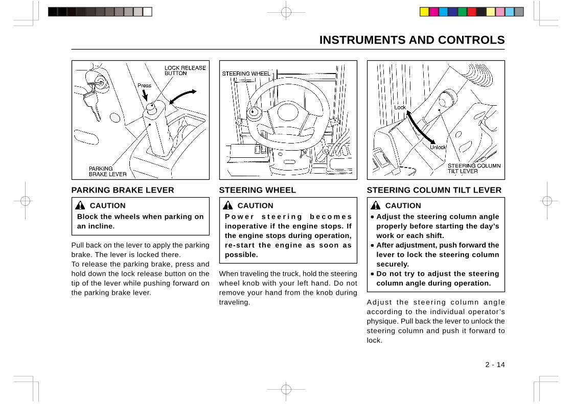
INSTRUMENTS AND CONTROLS
2 - 14
PARKING BRAKE LEVER
CAUTION
Block the wheels when parking onan incline.
Pull back on the lever to apply the parkingbrake. The lever is locked there.To release the parking brake, press andhold down the lock release button on thetip of the lever while pushing forward onthe parking brake lever.
STEERING COLUMN TILT LEVER
CAUTION
••••• Adjust the steering column angleproperly before starting the day’swork or each shift.
••••• After adjustment, push forward thelever to lock the steering columnsecurely.
••••• Do not try to adjust the steeringcolumn angle during operation.
Adjus t the s teer ing co lumn ang leaccording to the individual operator ’sphysique. Pull back the lever to unlock thesteering column and push it forward tolock.
STEERING WHEEL
CAUTION
P o w e r s t e e r i n g b e c o m e sinoperative if the engine stops. Ifthe engine stops during operation,re-start the engine as soon aspossible.
When traveling the truck, hold the steeringwheel knob with your left hand. Do notremove your hand from the knob duringtraveling.
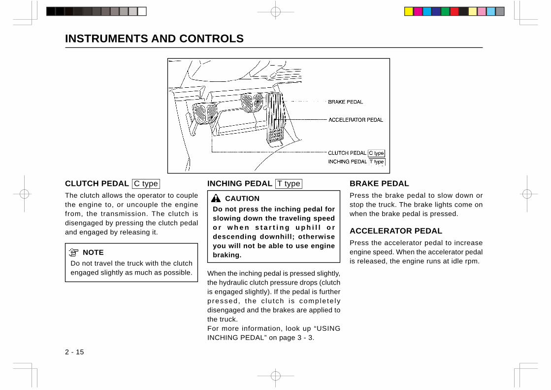
INSTRUMENTS AND CONTROLS
2 - 15
CLUTCH PEDAL C type
The clutch allows the operator to couplethe engine to, or uncouple the enginefrom, the transmission. The clutch isdisengaged by pressing the clutch pedaland engaged by releasing it.
NOTE
Do not travel the truck with the clutchengaged slightly as much as possible.
BRAKE PEDAL
Press the brake pedal to slow down orstop the truck. The brake lights come onwhen the brake pedal is pressed.
ACCELERATOR PEDAL
Press the accelerator pedal to increaseengine speed. When the accelerator pedalis released, the engine runs at idle rpm.
INCHING PEDAL T type
CAUTION
Do not press the inching pedal forslowing down the traveling speedo r w h e n s t a r t i n g u p h i l l o rdescending downhill; otherwiseyou will not be able to use enginebraking.
When the inching pedal is pressed slightly,the hydraulic clutch pressure drops (clutchis engaged slightly). If the pedal is furtherpressed, the c lu tch i s comple te lydisengaged and the brakes are applied tothe truck.For more information, look up “USINGINCHING PEDAL” on page 3 - 3.
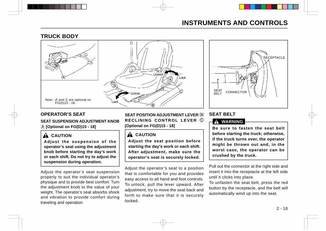
INSTRUMENTS AND CONTROLS
2 - 16
OPERATOR’S SEAT
SEAT SUSPENSION ADJUSTMENT KNOB [Optional on FG(D)15 - 18]
CAUTIONAdjust the suspension of theoperator’s seat using the adjustmentknob before starting the day’s workor each shift. Do not try to adjust thesuspension during operation.
Adjust the operator ’s seat suspensionproperly to suit the individual operator’sphysique and to provide best comfort. Turnthe adjustment knob to the value of yourweight. The operator’s seat absorbs shockand vibration to provide comfort duringtraveling and operation.
SEAT BELT
Be sure to fasten the seat beltbefore starting the truck; otherwise,if the truck turns over, the operatormight be thrown out and, in theworst case, the operator can becrushed by the truck.
Pull out the connector at the right side andinsert it into the receptacle at the left sideuntil it clicks into place.To unfasten the seat belt, press the redbutton by the receptacle, and the belt willautomatically wind up into the seat.
SEAT POSITION ADJUSTMENT LEVER RECLINING CONTROL LEVER [Optional on FG(D)15 - 18]
CAUTION
Adjust the seat position beforestarting the day’s work or each shift.After adjustment, make sure theoperator’s seat is securely locked.
Adjust the operator’s seat to a positionthat is comfortable for you and provideseasy access to all hand and foot controls.To unlock, pull the lever upward. Afteradjustment, try to move the seat back andforth to make sure that it is securelylocked.
TRUCK BODY
WARNING
SEATBELT CONNECTOR
RECEPTACLE
Note: and are optional onFG(D)15 - 18.
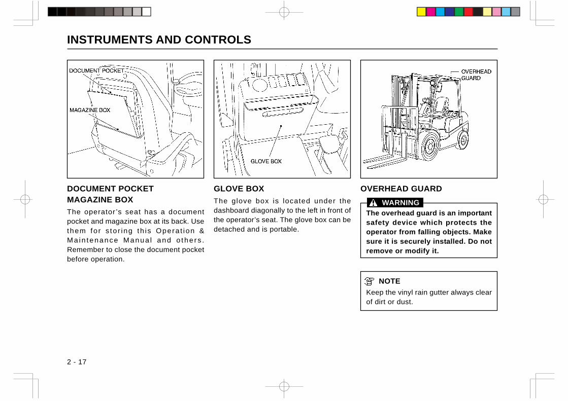
INSTRUMENTS AND CONTROLS
2 - 17
OVERHEAD GUARD
The overhead guard is an importantsafety device which protects theoperator from falling objects. Makesure it is securely installed. Do notremove or modify it.
NOTE
Keep the vinyl rain gutter always clearof dirt or dust.
GLOVE BOX
The glove box is located under thedashboard diagonally to the left in front ofthe operator’s seat. The glove box can bedetached and is portable.
DOCUMENT POCKETMAGAZINE BOX
The operator ’s seat has a documentpocket and magazine box at its back. Usethem for s to r ing th is Opera t ion &Ma in tenance Manua l and o the rs .Remember to close the document pocketbefore operation.
WARNING
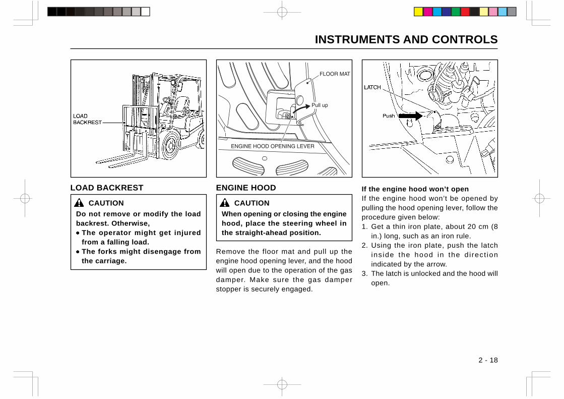
INSTRUMENTS AND CONTROLS
2 - 18
LOAD BACKREST
CAUTION
Do not remove or modify the loadbackrest. Otherwise,••••• The operator might get injured
from a falling load.••••• The forks might disengage from
the carriage.
If the engine hood won’t openIf the engine hood won’t be opened bypulling the hood opening lever, follow theprocedure given below:1. Get a thin iron plate, about 20 cm (8
in.) long, such as an iron rule.2. Using the iron plate, push the latch
ins ide the hood in the d i rect ionindicated by the arrow.
3. The latch is unlocked and the hood willopen.
ENGINE HOOD
CAUTION
When opening or closing the enginehood, place the steering wheel inthe straight-ahead position.
Remove the floor mat and pull up theengine hood opening lever, and the hoodwill open due to the operation of the gasdamper. Make sure the gas damperstopper is securely engaged.
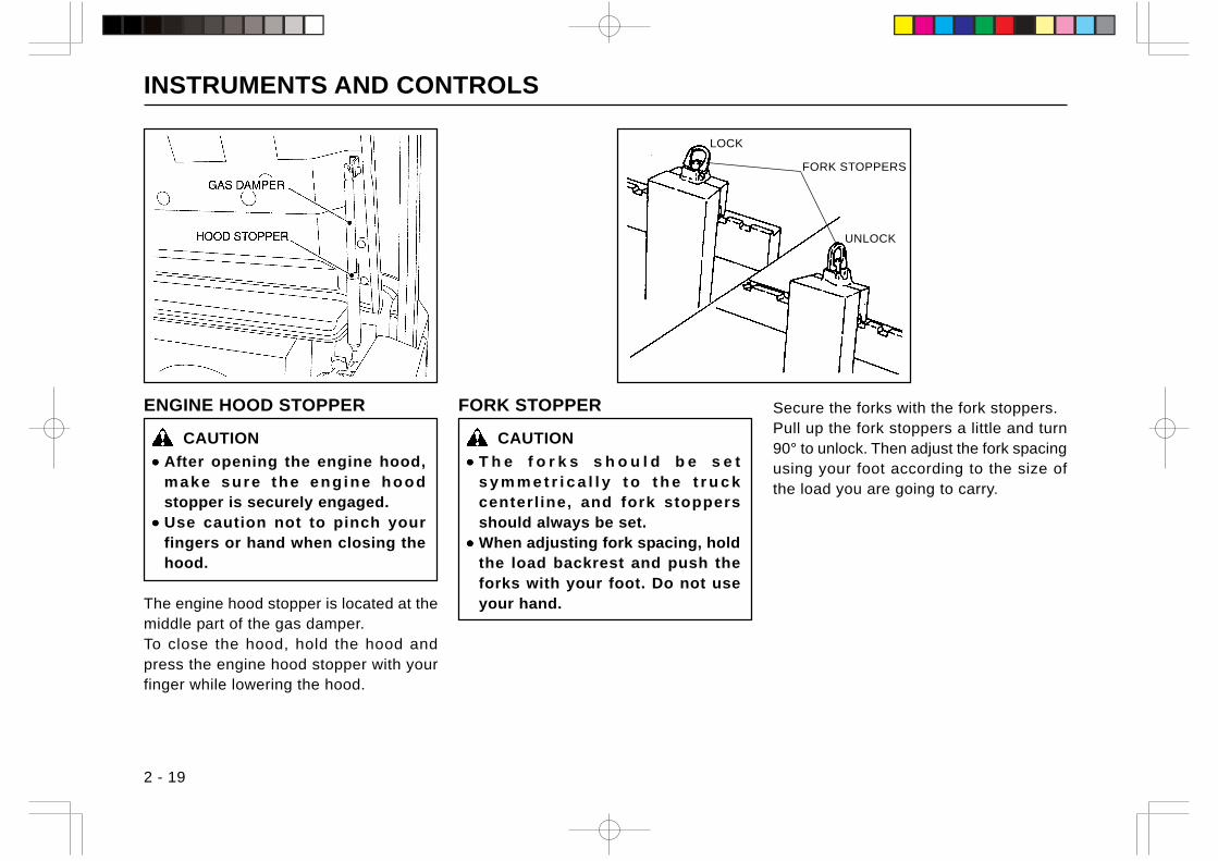
INSTRUMENTS AND CONTROLS
2 - 19
ENGINE HOOD STOPPER
CAUTION
••••• After opening the engine hood,make sure the eng ine hoodstopper is securely engaged.
••••• Use caution not to pinch yourfingers or hand when closing thehood.
The engine hood stopper is located at themiddle part of the gas damper.To close the hood, hold the hood andpress the engine hood stopper with yourfinger while lowering the hood.
FORK STOPPERS
FORK STOPPER
CAUTION
••••• T h e f o r k s s h o u l d b e s e ts y m m e t r i c a l l y t o t h e t r u c kcenterl ine, and fork stoppersshould always be set.
••••• When adjusting fork spacing, holdthe load backrest and push theforks with your foot. Do not useyour hand.
Secure the forks with the fork stoppers.Pull up the fork stoppers a little and turn90° to unlock. Then adjust the fork spacingusing your foot according to the size ofthe load you are going to carry.
LOCK
UNLOCK
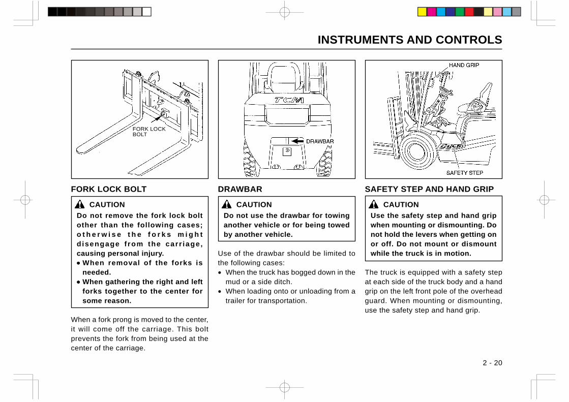
INSTRUMENTS AND CONTROLS
2 - 20
FORK LOCK BOLT
CAUTION
Do not remove the fork lock boltother than the following cases;o t h e r w i s e t h e f o r k s m i g h tdisengage f rom the carr iage,causing personal injury.••••• When removal of the forks is
needed.••••• When gathering the right and left
forks together to the center forsome reason.
When a fork prong is moved to the center,it will come off the carriage. This boltprevents the fork from being used at thecenter of the carriage.
FORK LOCKBOLT
SAFETY STEP AND HAND GRIP
CAUTION
Use the safety step and hand gripwhen mounting or dismounting. Donot hold the levers when getting onor off. Do not mount or dismountwhile the truck is in motion.
The truck is equipped with a safety stepat each side of the truck body and a handgrip on the left front pole of the overheadguard. When mounting or dismounting,use the safety step and hand grip.
DRAWBAR
CAUTION
Do not use the drawbar for towinganother vehicle or for being towedby another vehicle.
Use of the drawbar should be limited tothe following cases:• When the truck has bogged down in the
mud or a side ditch.• When loading onto or unloading from a
trailer for transportation.
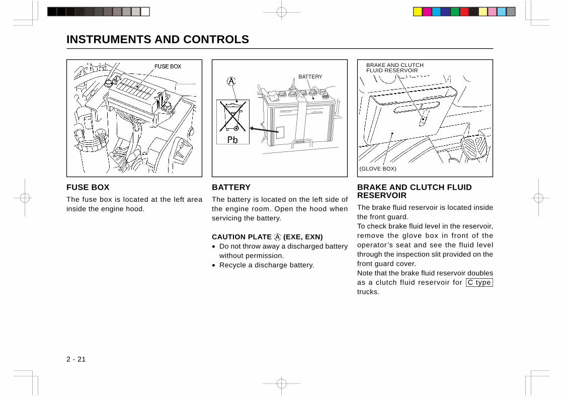
INSTRUMENTS AND CONTROLS
2 - 21
BRAKE AND CLUTCH FLUIDRESERVOIR
The brake fluid reservoir is located insidethe front guard.To check brake fluid level in the reservoir,remove the glove box in front of theoperator ’s seat and see the fluid levelthrough the inspection slit provided on thefront guard cover.Note that the brake fluid reservoir doublesas a clutch fluid reservoir for C type trucks.
FUSE BOX
The fuse box is located at the left areainside the engine hood.
(GLOVE BOX)
BRAKE AND CLUTCHFLUID RESERVOIR
BATTERY
The battery is located on the left side ofthe engine room. Open the hood whenservicing the battery.
CAUTION PLATE (EXE, EXN)• Do not throw away a discharged battery
without permission.• Recycle a discharge battery.
UPPER LEVEL LOWER LEVEL
•
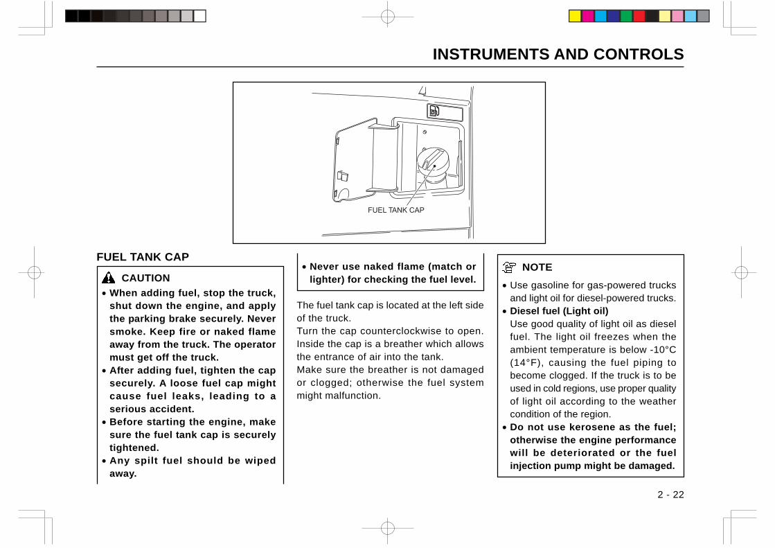
INSTRUMENTS AND CONTROLS
2 - 22
NOTE
• Use gasoline for gas-powered trucksand light oil for diesel-powered trucks.
• Diesel fuel (Light oil)Use good quality of light oil as dieselfuel. The light oil freezes when theambient temperature is below -10°C(14°F), causing the fuel piping tobecome clogged. If the truck is to beused in cold regions, use proper qualityof light oil according to the weathercondition of the region.
• Do not use kerosene as the fuel;otherwise the engine performancewill be deteriorated or the fuelinjection pump might be damaged.
FUEL TANK CAP
CAUTION
• When adding fuel, stop the truck,shut down the engine, and applythe parking brake securely. Neversmoke. Keep fire or naked flameaway from the truck. The operatormust get off the truck.
• After adding fuel, tighten the capsecurely. A loose fuel cap mightcause fuel leaks, leading to aserious accident.
• Before starting the engine, makesure the fuel tank cap is securelytightened.
• Any spilt fuel should be wipedaway.
• Never use naked flame (match orlighter) for checking the fuel level.
The fuel tank cap is located at the left sideof the truck.Turn the cap counterclockwise to open.Inside the cap is a breather which allowsthe entrance of air into the tank.Make sure the breather is not damagedor clogged; otherwise the fuel systemmight malfunction.
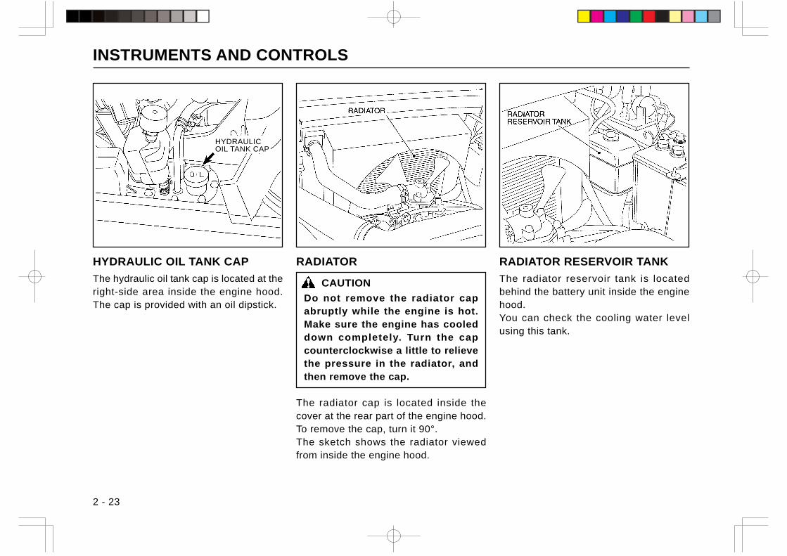
INSTRUMENTS AND CONTROLS
2 - 23
RADIATOR
CAUTION
Do not remove the radiator capabruptly while the engine is hot.Make sure the engine has cooleddown completely. Turn the capcounterclockwise a little to relievethe pressure in the radiator, andthen remove the cap.
The radiator cap is located inside thecover at the rear part of the engine hood.To remove the cap, turn it 90°.The sketch shows the radiator viewedfrom inside the engine hood.
RADIATOR RESERVOIR TANK
The radiator reservoir tank is locatedbehind the battery unit inside the enginehood.You can check the cooling water levelusing this tank.
HYDRAULIC OIL TANK CAP
The hydraulic oil tank cap is located at theright-side area inside the engine hood.The cap is provided with an oil dipstick.
HYDRAULICOIL TANK CAP
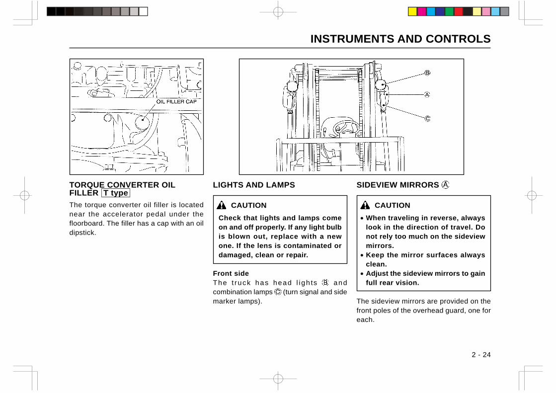
INSTRUMENTS AND CONTROLS
2 - 24
LIGHTS AND LAMPS
CAUTION
Check that lights and lamps comeon and off properly. If any light bulbis blown out, replace with a newone. If the lens is contaminated ordamaged, clean or repair.
Front sideThe t ruck has head l igh ts andcombination lamps (turn signal and sidemarker lamps).
SIDEVIEW MIRRORS
CAUTION
• When traveling in reverse, alwayslook in the direction of travel. Donot rely too much on the sideviewmirrors.
• Keep the mirror surfaces alwaysclean.
• Adjust the sideview mirrors to gainfull rear vision.
The sideview mirrors are provided on thefront poles of the overhead guard, one foreach.
TORQUE CONVERTER OILFILLER T type
The torque converter oil filler is locatednear the accelerator pedal under thefloorboard. The filler has a cap with an oildipstick.
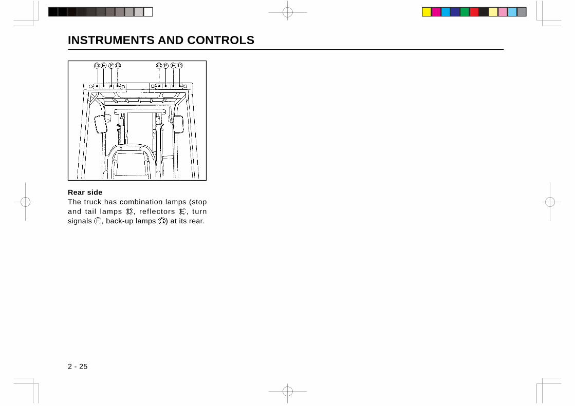
INSTRUMENTS AND CONTROLS
2 - 25
Rear sideThe truck has combination lamps (stopand tail lamps , reflectors , turnsignals , back-up lamps ) at its rear.
INSTRUMENTS AND CONTROLS
2 - 26
OPTIONAL EQUIPMENTHere are some pieces of optional equipmentwhich are deeply related to safe operationof the truck. For more information aboutoptional equipment, consult your local TCMdealer.
REAR WORK LIGHT (RWL)
CAUTION
It is advisable to use an optionalrear work l ight when you areworking in a place where sufficientlight is not available.
The rear work light illuminates the roador floor behind the truck at night to allowthe operator to recognize obstacles, if any,on the road or floor easily.
BEACON LIGHT
Use an optional beacon light in the casewhen the truck is required to work nearfellow workers or bystanders or when thework place is noisy.
SOUND VOLUME-ADJUSTABLEBACK-UP BUZZER
You can switch over the sound volumesin two stages, according to the noise levelat the work place.
SPEEDOMETER (SM)
The speedometer indicates the travelingspeed (km/h) and the distance traveled bythe truck.When the light switch is turned on, the dialis illuminated by a built-in lamp.
SPEED ALARM SYSTEM (SAS)
The SAS gives an alarm by sounding thebuzzer and flashing the beacon light whenthe traveling speed exceeds the presetspeed. The speed can be preset for5 km/h, 10 km/h or 15 km/h.
HIGH LOAD BACKREST (HBR)
Use the high load backrest for handlinghigh loads.
OVERHEAD GUARD WITH WIRENETTING
The overhead guard with wire nettingprotects the operator from falling objects,especially when handling small parts at ahigh place.
PNEUMATIC SHAPED CUSHIONTIRE (UNIQUE TIRE, TR01)
Use tires of this type when you are goingto work in an area where there are debrisor anything that might blow the tires onthe road or floor surface.
TIRE CHAIN (TC)
Fit tire chains over the tires of the truck toincrease traction and prevent skidding onroads covered with ice or snow.
NOTE
Some models may require tire chainfitting parts. For more information,consult your local TCM dealer.
FIRE EXTINGUISHER (FE)
Use the fire extinguisher for putting out afire. An optional fire extinguisher will beattached to one of the rear supports of theoverhead guard.
POWER BRAKE (POB)
CAUTION
The trucks with power brake havetwo hydraulic lines. Use ordinarybrake oil (vegetable oil) for onehaving the master cylinder and usehydraulic oil (mineral oil) for theother having the brake booster.Therefore, never try to use rubberparts other than those speciallydesigned for the power brakesystem.
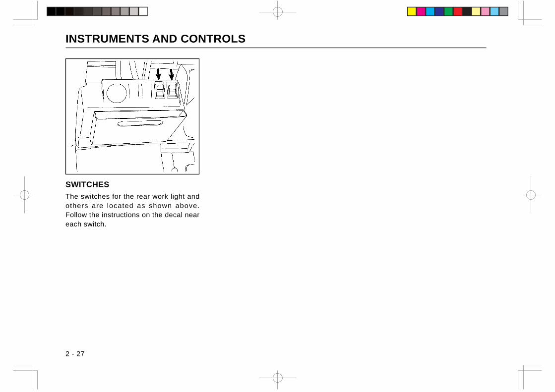
INSTRUMENTS AND CONTROLS
2 - 27
SWITCHES
The switches for the rear work light andothers are located as shown above.Follow the instructions on the decal neareach switch.
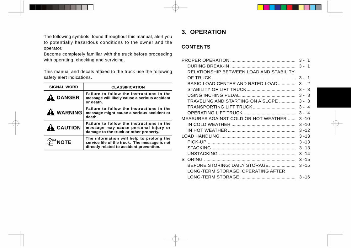
3. OPERATION
CONTENTS
PROPER OPERATION .................................................... 3 - 1DURING BREAK-IN .................................................... 3 - 1RELATIONSHIP BETWEEN LOAD AND STABILITYOF TRUCK................................................................... 3 - 1BASIC LOAD CENTER AND RATED LOAD.............. 3 - 2STABILITY OF LIFT TRUCK....................................... 3 - 3USING INCHING PEDAL ............................................ 3 - 3TRAVELING AND STARTING ON A SLOPE ............. 3 - 3TRANSPORTING LIFT TRUCK .................................. 3 - 4OPERATING LIFT TRUCK ......................................... 3 - 4
MEASURES AGAINST COLD OR HOT WEATHER ...... 3 -10IN COLD WEATHER ................................................... 3 -10IN HOT WEATHER...................................................... 3 -12
LOAD HANDLING ............................................................ 3 -13PICK-UP ...................................................................... 3 -13STACKING ................................................................... 3 -13UNSTACKING ............................................................. 3 -14
STORING ......................................................................... 3 -15BEFORE STORING; DAILY STORAGE ..................... 3 -15LONG-TERM STORAGE; OPERATING AFTERLONG-TERM STORAGE ............................................ 3 -16
The following symbols, found throughout this manual, alert youto potentially hazardous conditions to the owner and theoperator.Become completely familiar with the truck before proceedingwith operating, checking and servicing.
This manual and decals affixed to the truck use the followingsafety alert indications.
SIGNAL WORD CLASSIFICATION
Failure to follow the instructions in themessage will likely cause a serious accidentor death.
Failure to follow the instructions in themessage might cause a serious accident ordeath.
Failure to follow the instructions in themessage may cause personal injury ordamage to the truck or other property.
The information will help to prolong theservice life of the truck. The message is notdirectly related to accident prevention.
DANGER
WARNING
CAUTION
NOTE

PROPER OPERATION
3 - 1
RELATIONSHIP BETWEEN LOAD ANDSTABILITY OF TRUCKThe lift truck keeps a balance of weight between the truck andthe load on the forks with the center of the front wheels as afulcrum when the rated capacity load is placed in position.Due care should be paid to the weight and the load’s center ofgravity to maintain stability.
If the rated capacity is exceeded, there is a danger of the rearwheels being raised and in the worst case, the truck will turnover, resulting in a fatal accident. The load placed near thefork tips practically has the same effect that the weight of theload is increased. In this case, the load weight must be reducedaccordingly.
To operate the lift truck safely and get the most out of it, correctprocedures are described on the following pages:
DURING BREAK-INWe recommend to operate the truck under light load conditionsfor the first stage of operation to get the most from it. Especially,the requirements given below should be observed while thetruck is in a stage of 200 hours of operation.
Always warm up your truck before putting it into workregardless of the seasons.
Perform specified preventive maintenance servicescarefully and completely.
Never “race” or play games with the truck. Avoidsudden stops, starts or turns.
Oil changes and lubrication are recommended to doearlier than specified.
Do not run the engine needlessly at high rpm withoutload.
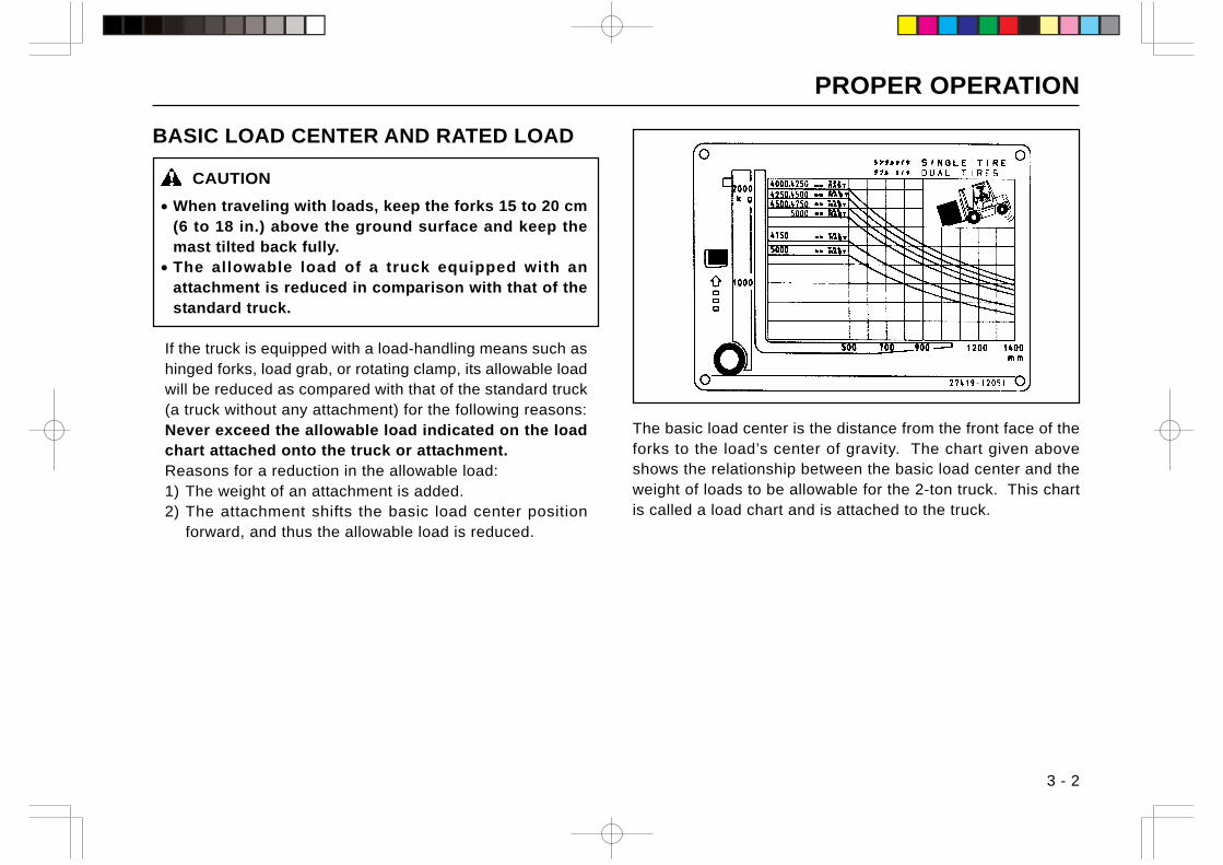
PROPER OPERATION
3 - 2
The basic load center is the distance from the front face of theforks to the load’s center of gravity. The chart given aboveshows the relationship between the basic load center and theweight of loads to be allowable for the 2-ton truck. This chartis called a load chart and is attached to the truck.
BASIC LOAD CENTER AND RATED LOAD
CAUTION
• When traveling with loads, keep the forks 15 to 20 cm(6 to 18 in.) above the ground surface and keep themast tilted back fully.
• The allowable load of a truck equipped with anattachment is reduced in comparison with that of thestandard truck.
If the truck is equipped with a load-handling means such ashinged forks, load grab, or rotating clamp, its allowable loadwill be reduced as compared with that of the standard truck(a truck without any attachment) for the following reasons:Never exceed the allowable load indicated on the loadchart attached onto the truck or attachment.Reasons for a reduction in the allowable load:1) The weight of an attachment is added.2) The attachment shifts the basic load center position
forward, and thus the allowable load is reduced.
PROPER OPERATION
3 - 3
STABILITY OF LIFT TRUCKThe stability of lift trucks is stipulated in JIS (Japanese IndustrialStandards) or in other national industrial standards, and TCMlift trucks are manufactured complying with these standards.However, note that the stability of lift trucks is not assured atall times, but only when the following conditions are properlyobserved.
• The ground or floor surface is level and hard.• The truck travels under standard loaded or unloaded
condition.• The truck is operated carefully and the forks are properly
manipulated; that is, the forks are not tilted forward morethan necessary, when stacking or unstacking.Load handling is carried out carefully and slowly.
In addition, keep the truck in good working condition for safeoperation and traveling.
Standard unloaded conditionThis means that the forks are raised 30 cm (12 in.) abovethe ground or floor surface and tilted back fully without loads.
Standard loaded conditionThis means that the forks are raised 30 cm (12 in.) abovethe ground or floor surface with a load placed at the basicload center position of the forks.
USING INCHING PEDAL T TYPEThe inching pedal works in the same manner as the clutch pedalof the C type truck.Use the inching pedal to move the truck inch by inch whileoperating the load handling means at high speed.1) Press the inching pedal to the floor.2) Place the shift lever into the forward (or reverse) position.3) Step on the accelerator pedal gradually while releasing the
inching pedal little by little, to move the truck inch by inch.
TRAVELING AND STARTING ON A SLOPE• When traveling on a slope with a load on the forks, have the
load pointed up-hill.When traveling on a slope without load, have the rear end ofthe truck pointed up-hill to prevent the drive wheels fromskidding.
• When going down a hill or starting on an incline, use thebrake pedal, but not the inching pedal. If the inching pedal ispressed on a downward slope, engine braking will not beavailable to make it difficult to brake the truck. If the inchingpedal is used when starting the truck on a slope, the truckmight slip down.
PROPER OPERATION
3 - 4
TRANSPORTING LIFT TRUCK
CAUTION
Transporting the lift truck on a trailer truck• Securely lock the lift truck in place to prevent it from
moving on the trailer truck by fastening with wireropes and blocking the wheels.
• When loading or unloading the lift truck onto or froma trailer truck or when traveling over public roads, payattention to the overall length, overall height, andweight and observe the local traffic regulations.
CAUTIONS TO BE TAKEN WHEN LOADING ANDUNLOADING LIFT TRUCK
CAUTION
• Never try to move the steering wheel when halfway upa ramp; otherwise the truck might fall down, leadingto a serious accident.
••••• Use ramps of sufficient length, width, and strength.••••• Before loading or unloading the lift truck, make sure
to apply the parking brake to the trailer truck and blockits wheels.
••••• Ramps must be securely locked to the trailer truck.Their surface must be clean and dry.
••••• Loading and unloading must be carried out on a levelsurface. The right and left ramps must be the sameheight.
••••• When loading the lift truck onto a trailer truck, back itup the ramps slowly with care.
OPERATING LIFT TRUCKMOUNTING AND DISMOUNTING
1) Make sure there is no approaching vehicle or passerby. Makesure the truck is at a complete stop.
2) Get on or off the truck from the left side of the truck, usingthe safety step and hand grip properly.
CAUTION
Do not hold the steering wheel when mounting ordismounting. Do not jump on or off the truck. You couldslip or fall and get injured.
3) Fasten your seat belt securely. The seat belt helps protectyou if there is an accident.
STARTING ENGINE AND AFTER ENGINE HASSTARTED
CAUTION
• Do not try to start the engine unless you are seatedproperly in the driver’s seat.
• Make sure there is no one around the truck beforestarting the engine.
• When starting the engine indoors, open the windows ordoors and run the fan to prevent exhaust gas poisoning.
Make sure the shift lever is in neutral “N” and the parking brakeis applied securely.1) Seat yourself in the driver’s seat and insert the starter key
into the starter switch.
PROPER OPERATION
3 - 5
2) Let other workmen and bystanders know you are starting upby honking.
3) Press the clutch pedal to the floor ( C type ) or brake pedal( T type ) and turn the starter switch to “START” (do not keepthe starter switch at “START” more than 10 seconds) to crankthe engine.
4) Once the engine has started, remove your hand from thekey and release the clutch pedal or brake pedal. The starterkey will automatically return to the “ON” position.
5) After the engine has started, do not increase the enginespeed rapidly. Warm up the engine and make sure theCHARGE warning light and ENGINE OIL PRESS. warninglight go out. In addition, make sure the meters are operatingnormally.
6) After the engine speed has stabilized, warm up the enginefurther at idling rpm.
WARMING UP ENGINE
Make sure to warm up the engine for about 5 minutes regardlessof whether the ambient temperature is cold or not.If the truck is operated before warming up the engine sufficiently,the inside of the engine is not properly lubricated and thecombustion is incomplete, thus resulting in a damaged engine.
STARTING COLD ENGINE
In a cold climate, the battery performance drops and theviscosity of the lubricating oil increases to make it difficult tocrank the engine.Start a cold engine using the following manner:
Gas-powered trucks
CAUTION
Engine speed is high immediately after the engine hasbeen started. Use caution when operating the shiftlevers and load handling levers.
• Turn the starter switch to the “START” position to engage thestarter motor to start the engine (Keep the accelerator pedalreleased).
• After the engine has started, warm up the engine.• If the engine won’t start on the first try, return the starter key to
the “OFF” position. Wait about 30 seconds before trying again.
NOTE
After the engine starts, release your foot from the acceleratorpedal. Do not race the engine.
Diesel-powered trucks
The preheating operation is automatically controlled accordingto the cooling water temperature.• Turn the starter key clockwise to the “ON” position.
The glow indicator comes on. It will go out when the engine hasbeen preheated.
• When the glow indicator goes out, press the accelerator pedaland turn the starter key to the “START” position to start the engine.Do not keep the starter motor engaged for more than 10 secondsat a time.
• If the engine won’t start on the first try, return the starter key tothe “OFF” position. Wait about 30 seconds before trying again.
PROPER OPERATION
3 - 6
2) Pull back on the tilt lever to tilt back the mast fully.3) Make sure there is no one around the truck and let other
workmen and bystanders know you are starting up byhonking.
STARTING LIFT TRUCK
CAUTION
Slow down when:• Making turns• Running at narrow aisles• Running on rough surfaces• Approaching to loads or obstacles.
C type1) Press the clutch pedal to the floor.2) Place the directional shift lever in the forward (reverse)
position.3) Place the speed range shift lever in the Low position.4) Press and hold down the parking brake release button while
releasing the parking brake lever.5) Press the accelerator pedal while releasing the clutch pedal
slowly to start the truck.
NOTE
Do not keep your foot on the clutch pedal after the truckhas started; otherwise the clutch disk wil l wear outprematurely.
WHEN ENGINE WON’T START
CAUTION
Never try to start the engine by pushing or towing thetruck.
• Do not keep the starter motor engaged for more than 10seconds at a time. If the engine does not start 10 secondsafter engaging the starter motor, stop the operation of thestarter motor. Wait for a while and start all over again.
• If the engine is hard to start despite several tries, check thefuel level in the fuel tank, the fuel system for mixing of air, orthe electrical wiring for a broken wire.
• The engine might not start if the starter motor does not reacha specified rpm. If this is the case, start the engine using anauxiliary battery and booster cable.
NOTE
For “Starting with Auxiliary Battery”, see page 4 - 29.
BEFORE STARTING LIFT TRUCK
CAUTION
Make sure there is no one around the truck and let otherworkmen and bystanders know you are starting up byhonking.
1) Pull back on the lift lever to raise the forks 15 to 20 cm (6 to8 in.) from the ground or floor surface.
PROPER OPERATION
3 - 7
T type
CAUTION
Press the brake pedal to the floor before placing theshift lever into the forward (or reverse) position;otherwise the truck starts moving slowly or creeps whenthe shift lever is placed into forward or reverse.
NOTE
Do not keep your foot on the inching pedal during travelingafter the truck has started.
1) Press the brake pedal.2) Place the shift lever in the forward (or reverse) position.3) Press and hold down the parking brake release button while
releasing the parking brake lever.4) Release the brake pedal and press the accelerator pedal to
start the truck.
GEARSHIFTING
CAUTION
When traveling in reverse, look in the direction of traveland be alert for pedestrians, other trucks or obstaclesin your path of travel. Do not rely too much on the sideview mirrors.
C type
• When reversing the direction of travel, from forward to reverseor vice versa, be sure to bring the truck to a complete stop.
• When changing the speed range from Low to High, start thetruck and accelerate the speed. Then, release the acceleratorpedal while pressing the clutch pedal and change the speedrange. Press the accelerator pedal while releasing the clutchpedal quickly.
T type
When reversing the direction of travel, from forward to reverseor vice versa, be sure to bring the truck to a complete stop.
SLOWING DOWN
C type
Release the accelerator pedal and press the clutch pedal. Placethe speed range shift lever into Low and press the acceleratorpedal while releasing the clutch pedal quickly. Press the brakepedal as necessary.
T type
Ease up on the accelerator pedal. If necessary, press the brakepedal.
PROPER OPERATION
CAUTION
Safe parking• Park the truck on a level ground, preferably in a wide
area.If parking the truck without load on a slope is unavoidable,position the load handling means down-hill and blockthe wheels to prevent accidental roll.
• Park the truck in a designated area or out-of-traffic area.If necessary, put signposts or signal lights around thetruck.
• Park the truck on a hard ground. Avoid soft ground, deepmud or slippery surfaces.
• If you cannot lower the forks on the ground due to abroken load handling system, put a caution cloth to thefork end and park in an out-of-traffic area.
• Pay attention to the ground condition because it mightbe slippery.
• Dismount from the truck after making sure it has come toa complete stop. Do not dismount from the truck inmotion.
• Never jump off the truck.• Dismount from the truck, facing the truck and using the
safety step and hand grip.
3 - 8
TURNING
CAUTION
Note that the rear end (counterweight) of the truckswings when you turn the truck.
Unlike general passenger cars, the steer wheels are located atthe rear of the truck. This causes the rear end of the truck toswing out when a turn is made. Slow down the truck and movetoward a side to which you are turning. The steering wheelshould be turned a bit earlier than as with the front-wheelsteering car.• Grab the steering wheel knob with your left hand.• Your right hand is used to operate the load handling levers.Put your right hand on your knee while you are not operatingthe load handling levers.
PARKING
Slow down the truck and press the brake pedal to bring thetruck to a stop. Press the clutch pedal ( C type ) and place theshift lever into the neutral “N” position.
NOTE
Do not stop the truck on an up-hill slope by controlling theaccelerator pedal; otherwise the clutch disk will wear out orthe torque converter oil temperature will rise abnormally.
PROPER OPERATION
3 - 9
Park the truck in an out-of-traffic area and follow the proceduregiven below:1) Pull the parking brake lever to the full to apply the parking
brake.2) Lower the forks on the ground.3) Turn the key switch “OFF” to shut down the engine.4) Remove the key and keep it sure.5) Dismount from the truck carefully.
GROUND CONDITION
CAUTION
• Use due caution when traveling on a rough surface.• When crossing a railroad, be sure to once stop, make
sure to be safe and cross the railroad track at an anglewherever possible.
• Go around obstacles such as rocks and stumps, orpot holes. If unavoidable, reduce the speed and goover slowly and carefully. Use caution not to damagethe bottom of the truck. Cross a small bump diagonallyif the aisle width is enough to do so.
Lift truck performance depends upon the ground condition orfloor condition and travel speed should be adjusted properly.
TRAVELING ON SNOWY OR FROZEN ROAD
CAUTION
Note that fitting of optional tire chains will increasetraction, but can hardly prevent the truck fromsideslipping.
When traveling on a snowy or frozen road, use tire chains. Avoidsudden acceleration, stops or turns; otherwise the truck mightskid to cause a serious accident.Control the traveling speed carefully using the accelerator pedal.
NOTE
Some trucks require the replacement of some parts whenusing tire chains.For more information, consult your local TCM dealer.
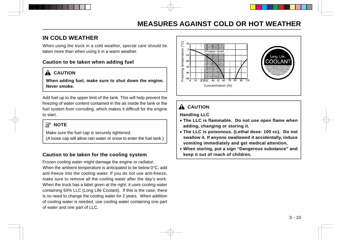
MEASURES AGAINST COLD OR HOT WEATHER
3 - 10
Fre
ezi
ng
te
mp
era
ture
(°C
)
Concentration (%)
Proper level
IN COLD WEATHERWhen using the truck in a cold weather, special care should betaken more than when using it in a warm weather.
Caution to be taken when adding fuel
CAUTION
When adding fuel, make sure to shut down the engine.Never smoke.
Add fuel up to the upper limit of the tank. This will help prevent thefreezing of water content contained in the air inside the tank or thefuel system from corroding, which makes it difficult for the engineto start.
NOTE
Make sure the fuel cap is securely tightened.(A loose cap will allow rain water or snow to enter the fuel tank.)
Caution to be taken for the cooling system
Frozen cooling water might damage the engine or radiator.When the ambient temperature is anticipated to be below 0°C, addanti-freeze into the cooling water. If you do not use anti-freeze,make sure to remove all the cooling water after the day’s work.When the truck has a label given at the right, it uses cooling watercontaining 50% LLC (Long Life Coolant). If this is the case, thereis no need to change the cooling water for 2 years. When additionof cooling water is needed, use cooling water containing one partof water and one part of LLC.
CAUTION
Handling LLC• The LLC is flammable. Do not use open flame when
adding, changing or storing it.• The LLC is poisonous. (Lethal dose: 100 cc). Do not
swallow it. If anyone swallowed it accidentally, inducevomiting immediately and get medical attention.
• When storing, put a sign “Dangerous substance” andkeep it out of reach of children.
MEASURES AGAINST COLD OR HOT WEATHER
3 - 11
Battery care
CAUTION
Never pour hot water over the battery case even if youfind it difficult to start the engine. The battery case mightbreak, causing a serious accident.
The battery hardly freezes and works efficiently when it iscompletely charged and has a greater specific gravity of theelectrolyte.If the electrolyte freezes, the battery case will be broken. Keepthe battery in fully charged condition at all times.The battery electrolyte usually freezes at about -35°C (-31°F)when the battery is in a fully charged condition.
To prevent freezing• Keep the battery’s state of charge to more than 75%.• Keep the specific gravity of electrolyte at 1.280 or less.• When the truck is not in use, remove the battery from the
truck and store in a warm place.
NOTE
When adding purified water to the battery, make sure toadd it immediately before charging or starting the truck.
DANGERCautions to be taken when handling battery
Gases produced by the battery can be explosive. Donot smoke. Do not use open flame for inspection.
• No fire. Do not smoke. Keep sparks or open flame awayfrom the battery.
• Keep proper electrolyte level. If the level is too low(below LOWER LEVEL), the battery will build up heat,leading to an explosion.
• Have a good ventilation. Do not use or store batteriesin a closed place or an area where ventilation is poor.
• Avoid electroshock accident. Wear rubber gloves whenservicing and inspecting the battery.
• Sulfuric acid. The electrolyte is sulfuric acid and thusit might cause burns or blindness if it comes in contactwith the skin, eye, or clothing.• If electrolyte comes in contact with your skin or
clothing, wash it away using a copious amount ofwater immediately.
• If electrolyte gets into your eyes, wash your eyes witha copious amount of water immediately and getmedical attention.
MEASURES AGAINST COLD OR HOT WEATHER
3 - 12
IN HOT WEATHER
Cooling system
CAUTION
Make sure the engine is cold before opening or closingthe radiator cap. Hot cooling water might spout out tocause serious burns.
To get a good cooling effect, use caution not to allow leakageof cooling water and the forming of scale or corrosion in thecooling system.• In hot weather, the cooling system is apt to cause scale or
corrosion. Use caution to get the circulation of clean waterat all times. The LLC can be used for all seasons, becauseit has anti-rust and anti-corrosion effect in addition to anti-freezing effect.
• A clogged radiator fin will cause an overheated engine. Keepthe radiator fins always clean. In addition, check for waterleaks.
• Check for a loose fan belt. If the fan belt is loose, adjust it forthe specified tension.
Measures to be taken when the engine hasoverheated
CAUTION
If the engine has overheated, do not open the radiatorcap. In addition, do not touch the radiator reservoirtank. Hot steam might spout out, causing burns.
When the engine has overheated:1) Let the engine run at idle rpm for a while and open the engine
hood fully to get a good ventilation.2) After making sure the temperature of the cooling water cools
down sufficiently, shut down the engine.3) Open the reservoir tank and add cooling water.4) Check for water leaks of the cooling system, clogged radiator
fin, and loose fan belt.
LOAD HANDLING
3 - 13
PICK-UP1) The fork spacing should be as wide as possible to maintain
proper balance of the load.2) Place the truck right in front of the load to be handled.3) The pallet should be evenly positioned across both forks.4) Insert the forks into the pallet as far as possible.5) To raise the load from the ground:
Once lift the forks 5 to 10 cm (2 to 4 in.) off the ground orfloor surface, and make sure the load is stable.After making sure the load is stable and evenly positionedon the forks, tilt back the mast fully and lift the forks up to20 cm (8 in.) off the ground or floor surface. Start running.
6) When handling a bulky load which restricts your vision, drivethe truck in reverse.
STACKING1) When approaching the deposit area, slow down your truck.2) Once stop the truck right in front of the area where your
load is to be deposited.3) Check the condition of the deposit position.4) Tilt the mast forward until the forks become horizontal.5) Raise the forks until they are a little higher than the deposit
position.
CAUTION
• Never tilt the mast forward with the load upraisedexcept when the forks are over the rack or a stack.
• Do not leave the truck with the load upraised.
6) Move forward slowly to place the load directly over thedesired area and stop the truck.
7) Make sure the load is just over the desired area. Slowlylower the load into position. Make sure the load is securelystacked.
8) Disengage the forks from the pallet or load using necessarylift-tilt operation, and then back away.
9) After making sure the fork tips leave the pallet or load, lowerthe forks to the basic traveling position (20 cm (8 in.) offthe ground or floor surface).
10) Tilt back the mast.
LOAD HANDLING
3 - 14
UNSTACKING1) When approaching the area where the load is to be retrieved,
slow down the truck.2) Once stop the truck right in front of the load so that the
distance between the fork tips and the load is about 30 cm(12 in.).
3) Check the condition of the stack.4) Tilt the mast forward until the forks become horizontal and
lift up to the position of the pallet or skid.5) Make sure the forks are positioned properly for the pallet.
Move forward slowly to insert the forks into the pallet as faras possible. Stop the truck.* If the forks are hard to be fully inserted, use the following
procedure:Move forward to insert 3/4 of the forks. Raise the forks 5to 10 cm (2 to 4 in.), back away 10 to 20 cm (4 to 8 in.)with the pallet or skid on the forks. Lower the pallet orskid on the stack.Move forward again to insert the forks into the pallet fully.
6) Raise the forks 5 to 10 cm (2 to 4 in.) off the stack.7) Check all around the truck to ensure that the path of travel
is unobstructed and back away slowly.8) Slowly lower the load to a height of 20 cm (8 in.) above the
ground or floor surface. Tilt back the mast fully and move tothe desired area.
STORING
3 - 15
DAILY STORAGE• Park the truck at a specified place and block the wheels.• Place the shift lever(s) in neutral “N” and pull the parking
brake lever fully.• Shut down the engine and operate the load handling levers
several times slowly to remove the residual pressure fromthe cylinders and hoses.
• Remove the starter key and keep it in a safe place.
BEFORE STORING
CAUTION
••••• If any time your lift truck is found to be in need of repair,defective or in any way unsafe, the condition shouldbe reported to the supervisor, and the truck should betaken out of service until it has been restored to safeoperating condition.
••••• Use caution to prevent electrical parts from getting wetwhen washing the truck.
Before storing the lift truck, clean it thoroughly and performinspection using the following procedure:• Wipe away grease, oil, etc., adhering to the body of the truck
with shop rag. Use water, if needed.• While washing the truck, check the general condition of the
truck. Especially check the truck body for dents or cracks,the tires for wear or nails or stones in the tread.
• Check the fuel level and add if necessary.• Check for leakage of hydraulic oil, engine oil, fuel or cooling
water.• Apply grease, where needed.• Check for looseness of the hub nuts and cylinder piston rod
joints.• Check the mast rollers to see that they rotate smoothly.• Lift the forks up to the top position and lower to the lower
limit. Repeat this procedure to prime oil into the lift cylinders.• Drain off the cooling water completely from the cooling system
in winter or cold weather if anti-freeze or LLC is not used.
STORING
3 - 16
OPERATING AFTER LONG-TERM STORAGE• Remove covers used to seal off moisture.• Remove antirust from the exposed parts.• Drain the crankcase, transmission ( C type ), differential, and
torque converter ( T type ), clean their inside and add newoil.
• Drain foreign matter and water from the hydraulic oil tankand fuel tank.
• Remove the engine cylinder head cover and lubricate thevalves and rocker shafts. Check the valves for properoperation.
• Add cooling water to the specified level.• Charge the battery and mount it on the truck. Connect the
cables.• Perform pre-operational checks carefully.• Warm up the engine.
LONG-TERM STORAGEPerform the following checks in addition to “BEFORE STORING”and “DAILY STORAGE” services.• Taking the rainy season into consideration, park the truck at
a higher and hard ground.• Remove the battery from the truck.• Even though the truck is parked indoors, if the place is hot or
humid, the battery should be kept in a dry, cool place, andcharged once a month.
• Apply anti-rust to the exposed parts such as cylinder rodsand shafts that tend to rust.
• Cover components which may be caught with humidity, suchas the air breather and air cleaner.
• Put the truck in the operating state once a week and startthe engine. Warm it up sufficiently before moving the truck alittle back and forth.
• Avoid parking on a soft ground such as an asphalt ground insummer.

MEMO
dJ E ・E ・E ・.-=!I I I I ベト l - ・E ・E ・. I I ・・ |二
十 十
1-¥ ベト ¥-F
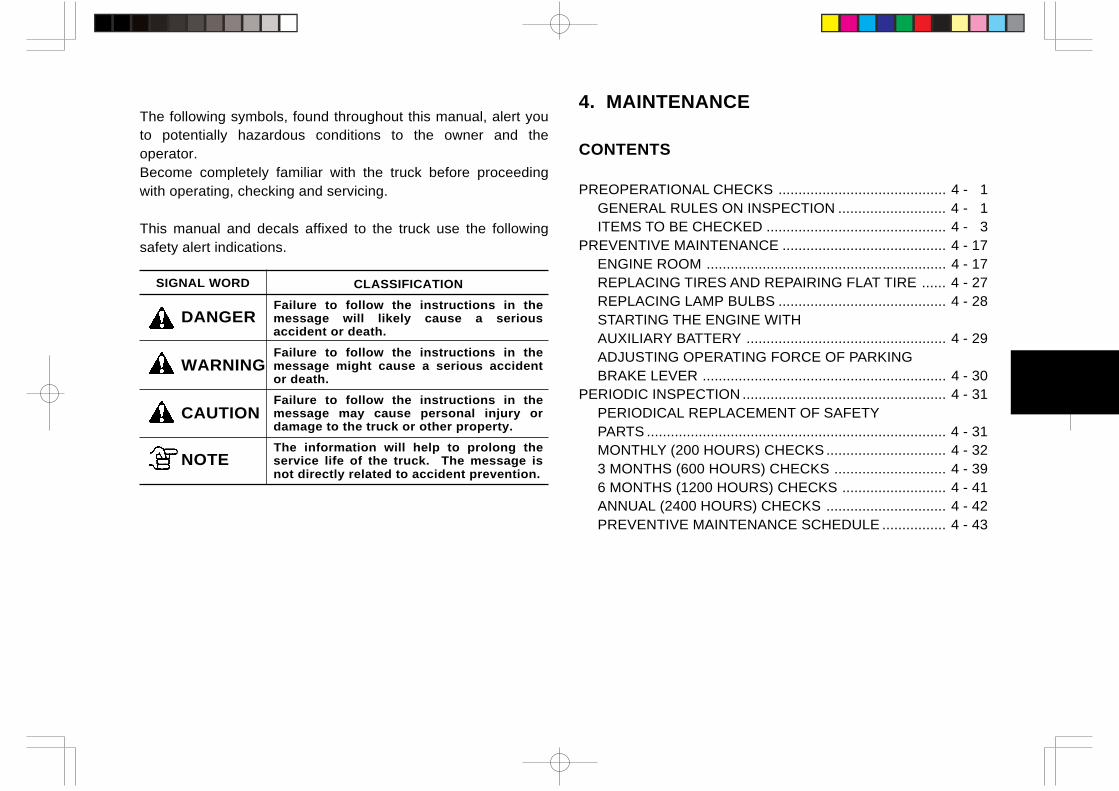
4. MAINTENANCE
CONTENTS
PREOPERATIONAL CHECKS .......................................... 4 - 1GENERAL RULES ON INSPECTION ........................... 4 - 1ITEMS TO BE CHECKED ............................................. 4 - 3
PREVENTIVE MAINTENANCE ......................................... 4 - 17ENGINE ROOM ............................................................ 4 - 17REPLACING TIRES AND REPAIRING FLAT TIRE ...... 4 - 27REPLACING LAMP BULBS .......................................... 4 - 28STARTING THE ENGINE WITHAUXILIARY BATTERY .................................................. 4 - 29ADJUSTING OPERATING FORCE OF PARKINGBRAKE LEVER ............................................................. 4 - 30
PERIODIC INSPECTION ................................................... 4 - 31PERIODICAL REPLACEMENT OF SAFETYPARTS ........................................................................... 4 - 31MONTHLY (200 HOURS) CHECKS .............................. 4 - 323 MONTHS (600 HOURS) CHECKS ............................ 4 - 396 MONTHS (1200 HOURS) CHECKS .......................... 4 - 41ANNUAL (2400 HOURS) CHECKS .............................. 4 - 42PREVENTIVE MAINTENANCE SCHEDULE ................ 4 - 43
The following symbols, found throughout this manual, alert youto potentially hazardous conditions to the owner and theoperator.Become completely familiar with the truck before proceedingwith operating, checking and servicing.
This manual and decals affixed to the truck use the followingsafety alert indications.
SIGNAL WORD CLASSIFICATION
Failure to follow the instructions in themessage will likely cause a seriousaccident or death.
Failure to follow the instructions in themessage might cause a serious accidentor death.
Failure to follow the instructions in themessage may cause personal injury ordamage to the truck or other property.
The information will help to prolong theservice life of the truck. The message isnot directly related to accident prevention.
DANGER
WARNING
CAUTION
NOTE
PREOPERATIONAL CHECKS
4 - 1
GENERAL RULES ON INSPECTION• Use TCM’s genuine parts only.• Use TCM’s genuine or recommended lubricants only.• Clean the oil fillers and grease fittings using a brush or
shop rag before adding oil or fuel or greasing.• Oil level checks and addition of oil should be made with
the truck parked on a level surface.• Preventive maintenance services should be done in an
orderly manner and due care taken to prevent personalinjury.
• If unavoidable to work under raised forks or attachment,use a stable support to prevent the forks or attachmentfrom falling down unexpectedly.
• Any time the operator finds that the truck or the controlsare not functioning properly, operation of the truck shouldbe halted and the condition reported to the supervisor.Never operate a faulty truck.
Before starting the lift truck, be sure to inspect the followingitems for safety’s sake and increased productivity.
CAUTION
• If any fault is found by preoperational inspection,attach a sign in the control area stating DO NOTOPERATE, remove the starter key and report thecondition to the supervisor. Operation of the truckshould be halted until the truck is completely repaired.
• Check for oil leaks. Remember that oil leaks mightcause a fire.
• Waste fluid caused from lubricant change servicesmust not be thrown away thoughtlessly, because theywill be a cause of air, water, earth pollution.The service personnel or employer is required todispose of it properly.
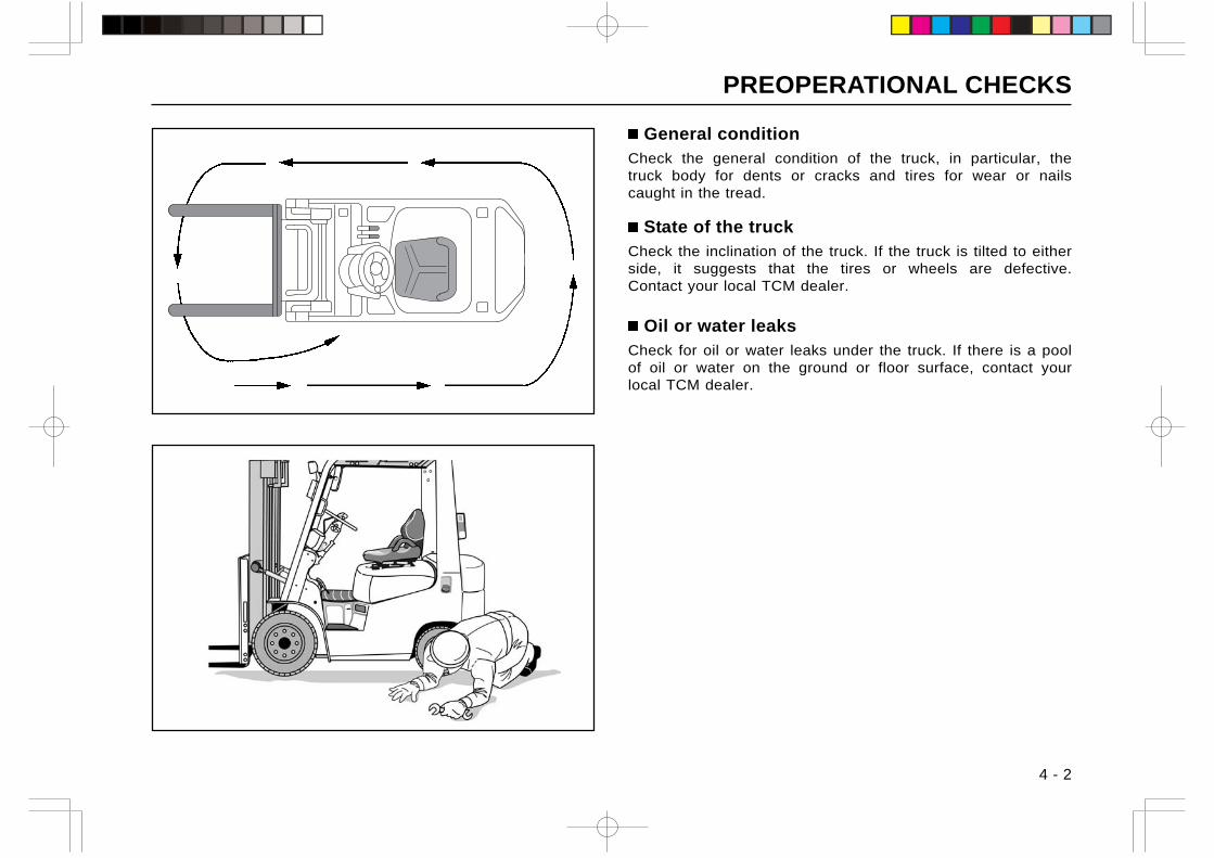
PREOPERATIONAL CHECKS
4 - 2
General conditionCheck the general condition of the truck, in particular, thetruck body for dents or cracks and tires for wear or nailscaught in the tread.
State of the truckCheck the inclination of the truck. If the truck is tilted to eitherside, it suggests that the tires or wheels are defective.Contact your local TCM dealer.
Oil or water leaksCheck for oil or water leaks under the truck. If there is a poolof oil or water on the ground or floor surface, contact yourlocal TCM dealer.
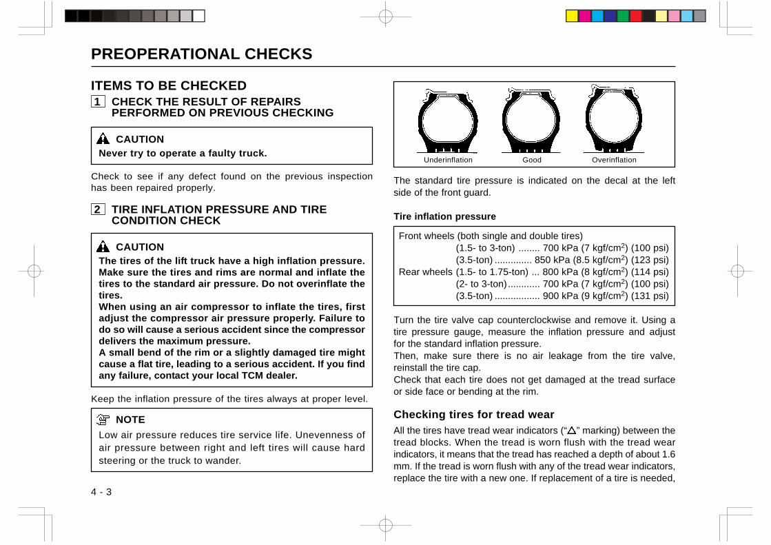
PREOPERATIONAL CHECKS
4 - 3
ITEMS TO BE CHECKED 1 CHECK THE RESULT OF REPAIRS
PERFORMED ON PREVIOUS CHECKING
CAUTIONNever try to operate a faulty truck.
Check to see if any defect found on the previous inspectionhas been repaired properly.
2 TIRE INFLATION PRESSURE AND TIRECONDITION CHECK
CAUTIONThe tires of the lift truck have a high inflation pressure.Make sure the tires and rims are normal and inflate thetires to the standard air pressure. Do not overinflate thetires.When using an air compressor to inflate the tires, firstadjust the compressor air pressure properly. Failure todo so will cause a serious accident since the compressordelivers the maximum pressure.A small bend of the rim or a slightly damaged tire mightcause a flat tire, leading to a serious accident. If you findany failure, contact your local TCM dealer.
Keep the inflation pressure of the tires always at proper level.
NOTE
Low air pressure reduces tire service life. Unevenness ofair pressure between right and left tires will cause hardsteering or the truck to wander.
The standard tire pressure is indicated on the decal at the leftside of the front guard.
Tire inflation pressure
Front wheels (both single and double tires)(1.5- to 3-ton) ........ 700 kPa (7 kgf/cm2) (100 psi)(3.5-ton) .............. 850 kPa (8.5 kgf/cm2) (123 psi)
Rear wheels (1.5- to 1.75-ton) ... 800 kPa (8 kgf/cm2) (114 psi)(2- to 3-ton)............ 700 kPa (7 kgf/cm2) (100 psi)(3.5-ton) ................. 900 kPa (9 kgf/cm2) (131 psi)
Turn the tire valve cap counterclockwise and remove it. Using atire pressure gauge, measure the inflation pressure and adjustfor the standard inflation pressure.Then, make sure there is no air leakage from the tire valve,reinstall the tire cap.Check that each tire does not get damaged at the tread surfaceor side face or bending at the rim.
Checking tires for tread wear
All the tires have tread wear indicators (“ ” marking) between thetread blocks. When the tread is worn flush with the tread wearindicators, it means that the tread has reached a depth of about 1.6mm. If the tread is worn flush with any of the tread wear indicators,replace the tire with a new one. If replacement of a tire is needed,
OverinflationUnderinflation Good
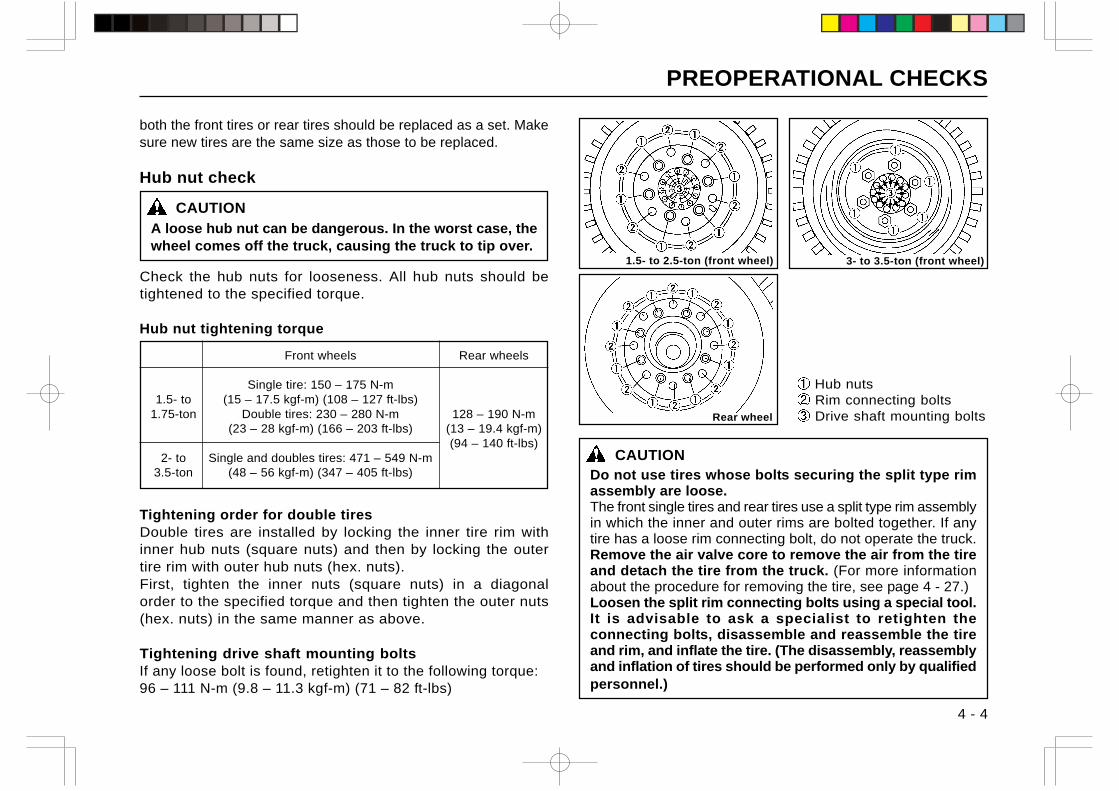
PREOPERATIONAL CHECKS
4 - 4
Hub nuts Rim connecting bolts Drive shaft mounting bolts
1.5- to 2.5-ton (front wheel) 3- to 3.5-ton (front wheel)
CAUTIONDo not use tires whose bolts securing the split type rimassembly are loose.The front single tires and rear tires use a split type rim assemblyin which the inner and outer rims are bolted together. If anytire has a loose rim connecting bolt, do not operate the truck.Remove the air valve core to remove the air from the tireand detach the tire from the truck. (For more informationabout the procedure for removing the tire, see page 4 - 27.)Loosen the split rim connecting bolts using a special tool.It is advisable to ask a specialist to retighten theconnecting bolts, disassemble and reassemble the tireand rim, and inflate the tire. (The disassembly, reassemblyand inflation of tires should be performed only by qualifiedpersonnel.)
Hub nut check
CAUTIONA loose hub nut can be dangerous. In the worst case, thewheel comes off the truck, causing the truck to tip over.
Check the hub nuts for looseness. All hub nuts should betightened to the specified torque.
Hub nut tightening torque
Front wheels Rear wheels
Single tire: 150 – 175 N-m1.5- to (15 – 17.5 kgf-m) (108 – 127 ft-lbs)
1.75-ton Double tires: 230 – 280 N-m 128 – 190 N-m(23 – 28 kgf-m) (166 – 203 ft-lbs) (13 – 19.4 kgf-m)
(94 – 140 ft-lbs)2- to Single and doubles tires: 471 – 549 N-m
3.5-ton (48 – 56 kgf-m) (347 – 405 ft-lbs)
Tightening order for double tiresDouble tires are installed by locking the inner tire rim withinner hub nuts (square nuts) and then by locking the outertire rim with outer hub nuts (hex. nuts).First, tighten the inner nuts (square nuts) in a diagonalorder to the specified torque and then tighten the outer nuts(hex. nuts) in the same manner as above.
Tightening drive shaft mounting boltsIf any loose bolt is found, retighten it to the following torque:96 – 111 N-m (9.8 – 11.3 kgf-m) (71 – 82 ft-lbs)
Rear wheel
both the front tires or rear tires should be replaced as a set. Makesure new tires are the same size as those to be replaced.
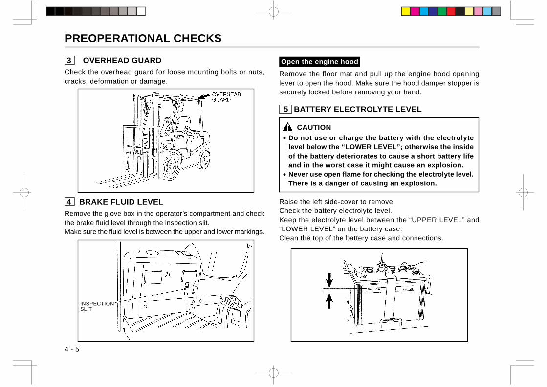
PREOPERATIONAL CHECKS
4 - 5
Open the engine hood
Remove the floor mat and pull up the engine hood openinglever to open the hood. Make sure the hood damper stopper issecurely locked before removing your hand.
5 BATTERY ELECTROLYTE LEVEL
CAUTION
• Do not use or charge the battery with the electrolytelevel below the “LOWER LEVEL”; otherwise the insideof the battery deteriorates to cause a short battery lifeand in the worst case it might cause an explosion.
• Never use open flame for checking the electrolyte level.There is a danger of causing an explosion.
Raise the left side-cover to remove.Check the battery electrolyte level.Keep the electrolyte level between the “UPPER LEVEL” and“LOWER LEVEL” on the battery case.Clean the top of the battery case and connections.
3 OVERHEAD GUARD
Check the overhead guard for loose mounting bolts or nuts,cracks, deformation or damage.
4 BRAKE FLUID LEVEL
Remove the glove box in the operator’s compartment and checkthe brake fluid level through the inspection slit.Make sure the fluid level is between the upper and lower markings.
INSPECTIONSLIT
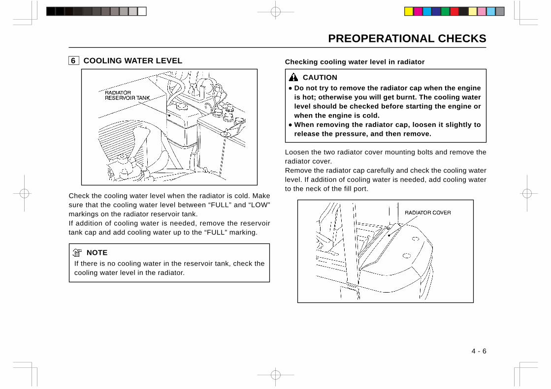
PREOPERATIONAL CHECKS
4 - 6
Checking cooling water level in radiator
CAUTION
••••• Do not try to remove the radiator cap when the engineis hot; otherwise you will get burnt. The cooling waterlevel should be checked before starting the engine orwhen the engine is cold.
••••• When removing the radiator cap, loosen it slightly torelease the pressure, and then remove.
Loosen the two radiator cover mounting bolts and remove theradiator cover.Remove the radiator cap carefully and check the cooling waterlevel. If addition of cooling water is needed, add cooling waterto the neck of the fill port.
6 COOLING WATER LEVEL
Check the cooling water level when the radiator is cold. Makesure that the cooling water level between “FULL” and “LOW”markings on the radiator reservoir tank.If addition of cooling water is needed, remove the reservoirtank cap and add cooling water up to the “FULL” marking.
NOTE
If there is no cooling water in the reservoir tank, check thecooling water level in the radiator.
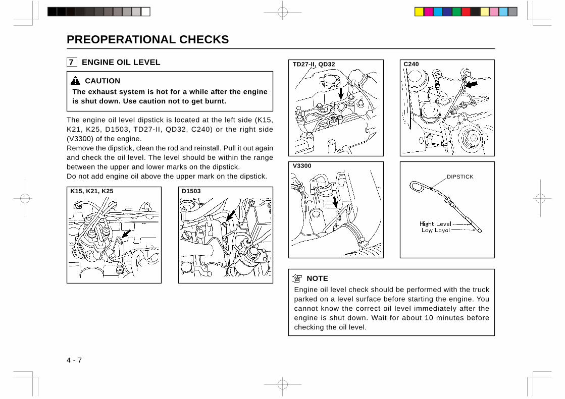
PREOPERATIONAL CHECKS
4 - 7
C240TD27-II, QD32
K15, K21, K25
7 ENGINE OIL LEVEL
CAUTION
The exhaust system is hot for a while after the engineis shut down. Use caution not to get burnt.
The engine oil level dipstick is located at the left side (K15,K21, K25, D1503, TD27-II, QD32, C240) or the right side(V3300) of the engine.Remove the dipstick, clean the rod and reinstall. Pull it out againand check the oil level. The level should be within the rangebetween the upper and lower marks on the dipstick.Do not add engine oil above the upper mark on the dipstick.
NOTE
Engine oil level check should be performed with the truckparked on a level surface before starting the engine. Youcannot know the correct oil level immediately after theengine is shut down. Wait for about 10 minutes beforechecking the oil level.
DIPSTICK
•
V3300
D1503
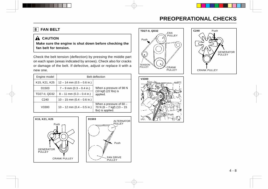
PREOPERATIONAL CHECKS
4 - 8
Push
GENERATORPULLEY
CRANK PULLEY
Push
GENERATORPULLEY
CRANK PULLEY
Push
CRANKPULLEY
TENSIONPULLEY
8 FAN BELT
CAUTION
Make sure the engine is shut down before checking thefan belt for tension.
Check the belt tension (deflection) by pressing the middle parton each span (areas indicated by arrows). Check also for cracksor damage of the belt. If defective, adjust or replace it with anew one.
K15, K21, K25
C240TD27-II, QD32
V3300
FANPULLEY
•
•
•
Push
D1503
Push
ALTERNATORPULLEY
FAN DRIVEPULLEY
Engine model Belt deflection
K15, K21, K25 12 – 14 mm (0.5 – 0.6 in.)
D1503 7 – 9 mm (0.3 – 0.4 in.)
TD27-II, QD32 8 – 11 mm (0.3 – 0.4 in.)
C240 10 – 15 mm (0.4 – 0.6 in.)
V3300 10 – 12 mm (0.4 – 0.5 in.)When a pressure of 60 –70 N (6 – 7 kgf) (13 – 15lbs) is applied.
When a pressure of 98 N(10 kgf) (22 lbs) isapplied.
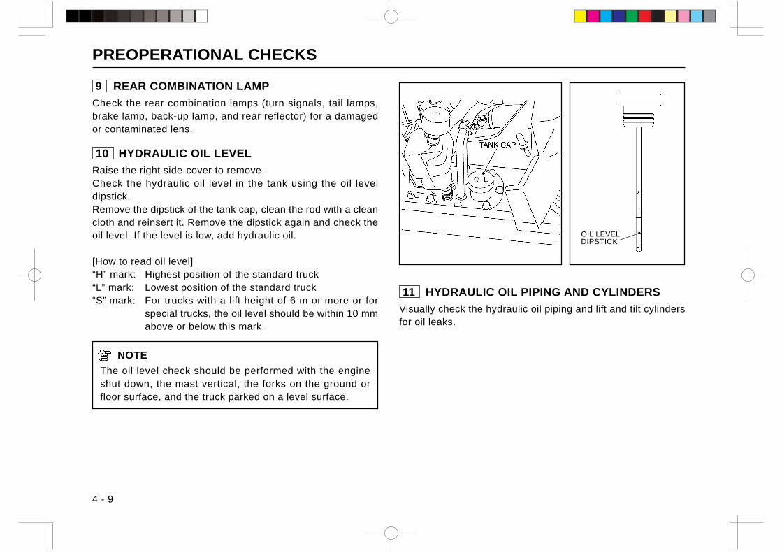
PREOPERATIONAL CHECKS
4 - 9
11 HYDRAULIC OIL PIPING AND CYLINDERS
Visually check the hydraulic oil piping and lift and tilt cylindersfor oil leaks.
9 REAR COMBINATION LAMP
Check the rear combination lamps (turn signals, tail lamps,brake lamp, back-up lamp, and rear reflector) for a damagedor contaminated lens.
10 HYDRAULIC OIL LEVEL
Raise the right side-cover to remove.Check the hydraulic oil level in the tank using the oil leveldipstick.Remove the dipstick of the tank cap, clean the rod with a cleancloth and reinsert it. Remove the dipstick again and check theoil level. If the level is low, add hydraulic oil.
[How to read oil level]“H” mark: Highest position of the standard truck“L” mark: Lowest position of the standard truck“S” mark: For trucks with a lift height of 6 m or more or for
special trucks, the oil level should be within 10 mmabove or below this mark.
NOTE
The oil level check should be performed with the engineshut down, the mast vertical, the forks on the ground orfloor surface, and the truck parked on a level surface.
OIL LEVELDIPSTICK
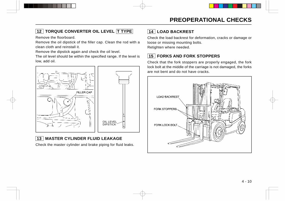
PREOPERATIONAL CHECKS
4 - 10
12 TORQUE CONVERTER OIL LEVEL T TYPE
Remove the floorboard.Remove the oil dipstick of the filler cap. Clean the rod with aclean cloth and reinstall it.Remove the dipstick again and check the oil level.The oil level should be within the specified range. If the level islow, add oil.
OIL LEVELDIPSTICK
13 MASTER CYLINDER FLUID LEAKAGE
Check the master cylinder and brake piping for fluid leaks.
14 LOAD BACKREST
Check the load backrest for deformation, cracks or damage orloose or missing mounting bolts.Retighten where needed.
15 FORKS AND FORK STOPPERS
Check that the fork stoppers are properly engaged, the forklock bolt at the middle of the carriage is not damaged, the forksare not bent and do not have cracks.
PREOPERATIONAL CHECKS
4 - 11
16 HEAD LIGHTS AND COMBINATION LAMPS
Check for dirty or damaged lens of the head lights. Check alsothe front and rear combination lamps (side marker lights andturn signals) for a dirty or damaged lens.
Close the engine hood
CAUTION
Take care not to pinch your fingers in the engine hood.
Reinstall the right and left side-covers and floorboard.Close the engine hood and lay the floor mat.
17 ADJUSTING OPERATOR’S SEAT ANDSTEERING COLUMN ANGLE
Seat yourself in the operator’s seat and adjust the operator’sseat to a position which provides easy access to all foot andhand controls. Also make sure you can operate the steeringwheel smoothly.After adjustment of the operator’s seat position and steeringcolumn angle, lock the seat and steering column securely.
18 SIDEVIEW MIRRORS
Check the sideview mirrors for contamination or damage.Adjust the mirrors to gain full rearview when you are seated inthe operator’s seat.
19 SHIFT LEVERS
Check the directional and speed range shift levers ( C type )and shift lever ( T type ) for looseness and smooth operation.
20 LOAD HANDLING LEVERS
CAUTION
Note that the forks drop when the lift lever is pushedforward even if the engine is not running.
Check the load handling levers (lift, tilt and attachment) forlooseness and smooth operation.
21 PARKING BRAKE OPERATION
Pull the parking brake lever to check if the parking brake isproperly applied and the lever is securely locked.
Start the engine
CAUTION
Make sure the shift levers are in neutral and the parkingbrake is applied before starting the engine.
22 WARNING LIGHTS
Turn the starter switch from “OFF” to “ON”. Make sure thewarning lights come on in red and go out soon after the enginehas started.
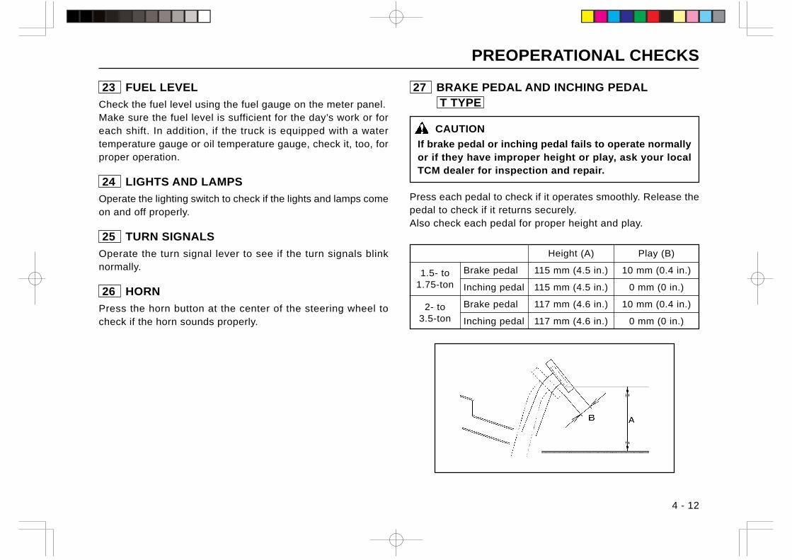
PREOPERATIONAL CHECKS
4 - 12
23 FUEL LEVEL
Check the fuel level using the fuel gauge on the meter panel.Make sure the fuel level is sufficient for the day’s work or foreach shift. In addition, if the truck is equipped with a watertemperature gauge or oil temperature gauge, check it, too, forproper operation.
24 LIGHTS AND LAMPS
Operate the lighting switch to check if the lights and lamps comeon and off properly.
25 TURN SIGNALS
Operate the turn signal lever to see if the turn signals blinknormally.
26 HORN
Press the horn button at the center of the steering wheel tocheck if the horn sounds properly.
27 BRAKE PEDAL AND INCHING PEDAL T TYPE
CAUTION
If brake pedal or inching pedal fails to operate normallyor if they have improper height or play, ask your localTCM dealer for inspection and repair.
Press each pedal to check if it operates smoothly. Release thepedal to check if it returns securely.Also check each pedal for proper height and play.
Height (A) Play (B)
1.5- to Brake pedal 115 mm (4.5 in.) 10 mm (0.4 in.)
1.75-ton Inching pedal 115 mm (4.5 in.) 0 mm (0 in.)
2- to Brake pedal 117 mm (4.6 in.) 10 mm (0.4 in.)
3.5-ton Inching pedal 117 mm (4.6 in.) 0 mm (0 in.)
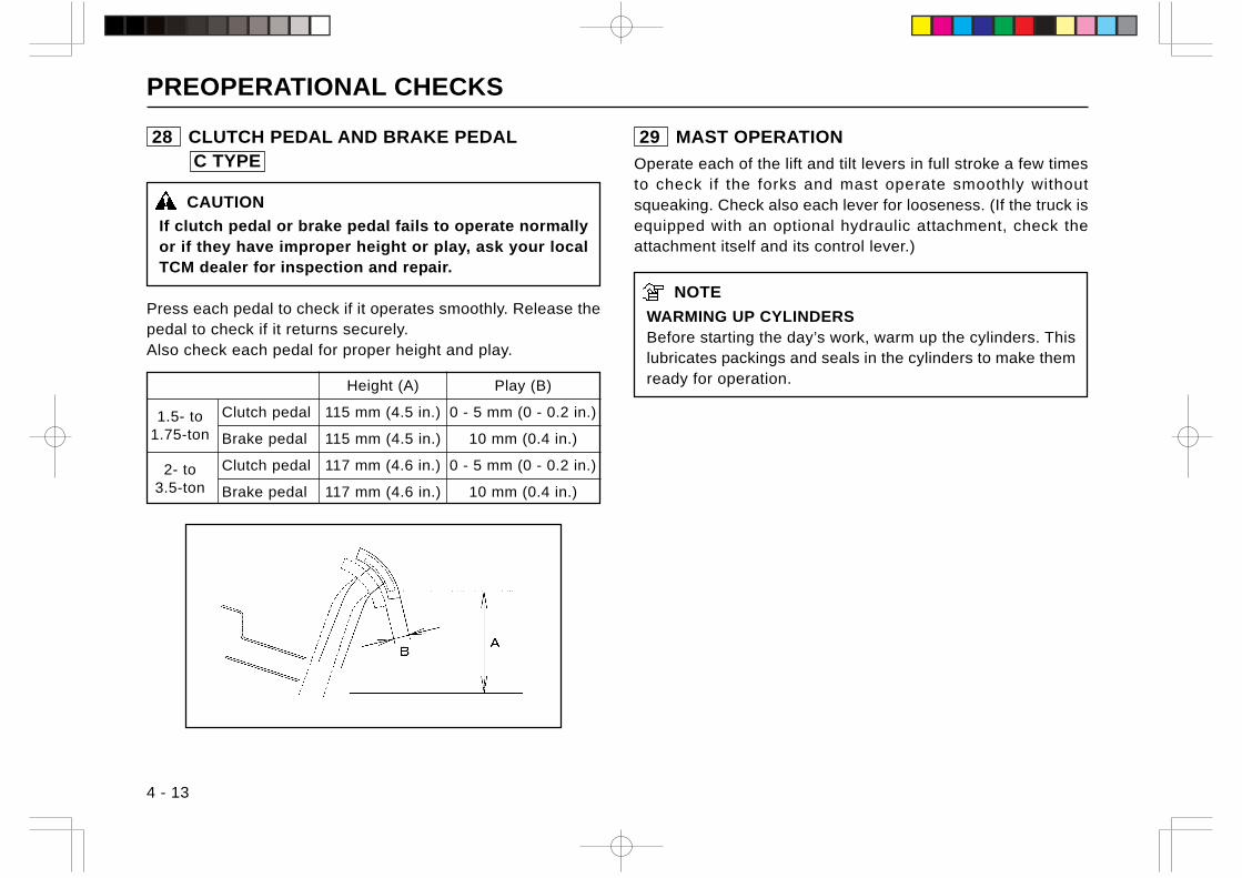
PREOPERATIONAL CHECKS
4 - 13
28 CLUTCH PEDAL AND BRAKE PEDAL C TYPE
CAUTION
If clutch pedal or brake pedal fails to operate normallyor if they have improper height or play, ask your localTCM dealer for inspection and repair.
Press each pedal to check if it operates smoothly. Release thepedal to check if it returns securely.Also check each pedal for proper height and play.
29 MAST OPERATION
Operate each of the lift and tilt levers in full stroke a few timesto check if the forks and mast operate smoothly withoutsqueaking. Check also each lever for looseness. (If the truck isequipped with an optional hydraulic attachment, check theattachment itself and its control lever.)
NOTE
WARMING UP CYLINDERSBefore starting the day’s work, warm up the cylinders. Thislubricates packings and seals in the cylinders to make themready for operation.Height (A) Play (B)
1.5- to Clutch pedal 115 mm (4.5 in.) 0 - 5 mm (0 - 0.2 in.)
1.75-ton Brake pedal 115 mm (4.5 in.) 10 mm (0.4 in.)
2- to Clutch pedal 117 mm (4.6 in.) 0 - 5 mm (0 - 0.2 in.)
3.5-ton Brake pedal 117 mm (4.6 in.) 10 mm (0.4 in.)
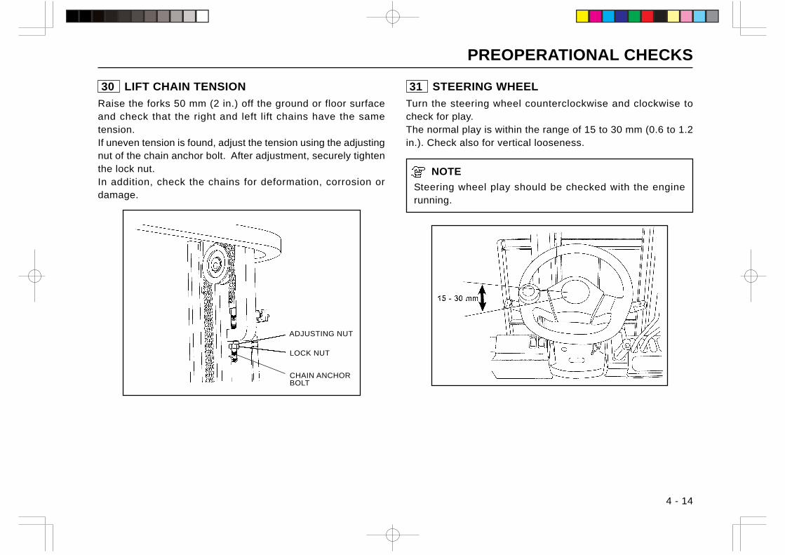
PREOPERATIONAL CHECKS
4 - 14
30 LIFT CHAIN TENSION
Raise the forks 50 mm (2 in.) off the ground or floor surfaceand check that the right and left lift chains have the sametension.If uneven tension is found, adjust the tension using the adjustingnut of the chain anchor bolt. After adjustment, securely tightenthe lock nut.In addition, check the chains for deformation, corrosion ordamage.
ADJUSTING NUT
LOCK NUT
31 STEERING WHEEL
Turn the steering wheel counterclockwise and clockwise tocheck for play.The normal play is within the range of 15 to 30 mm (0.6 to 1.2in.). Check also for vertical looseness.
NOTE
Steering wheel play should be checked with the enginerunning.
CHAIN ANCHORBOLT
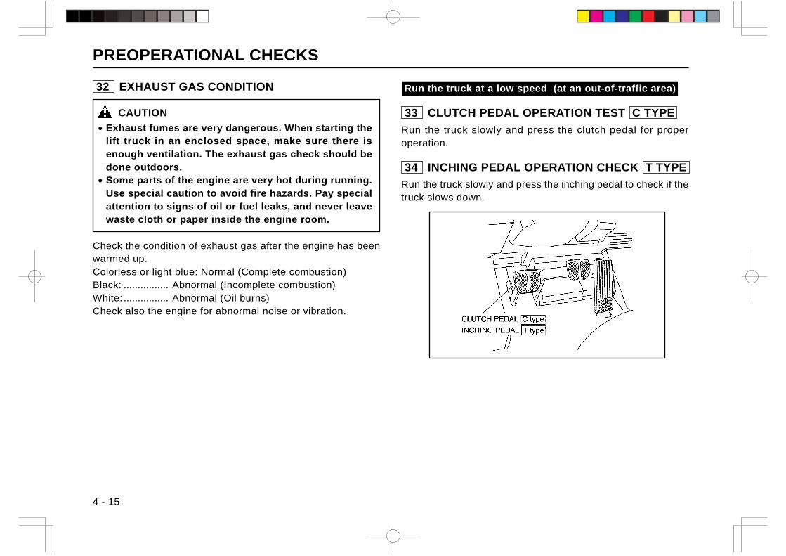
PREOPERATIONAL CHECKS
4 - 15
Run the truck at a low speed (at an out-of-traffic area)
33 CLUTCH PEDAL OPERATION TEST C TYPE
Run the truck slowly and press the clutch pedal for properoperation.
34 INCHING PEDAL OPERATION CHECK T TYPE
Run the truck slowly and press the inching pedal to check if thetruck slows down.
32 EXHAUST GAS CONDITION
CAUTION
• Exhaust fumes are very dangerous. When starting thelift truck in an enclosed space, make sure there isenough ventilation. The exhaust gas check should bedone outdoors.
• Some parts of the engine are very hot during running.Use special caution to avoid fire hazards. Pay specialattention to signs of oil or fuel leaks, and never leavewaste cloth or paper inside the engine room.
Check the condition of exhaust gas after the engine has beenwarmed up.Colorless or light blue: Normal (Complete combustion)Black: ................ Abnormal (Incomplete combustion)White: ................ Abnormal (Oil burns)Check also the engine for abnormal noise or vibration.
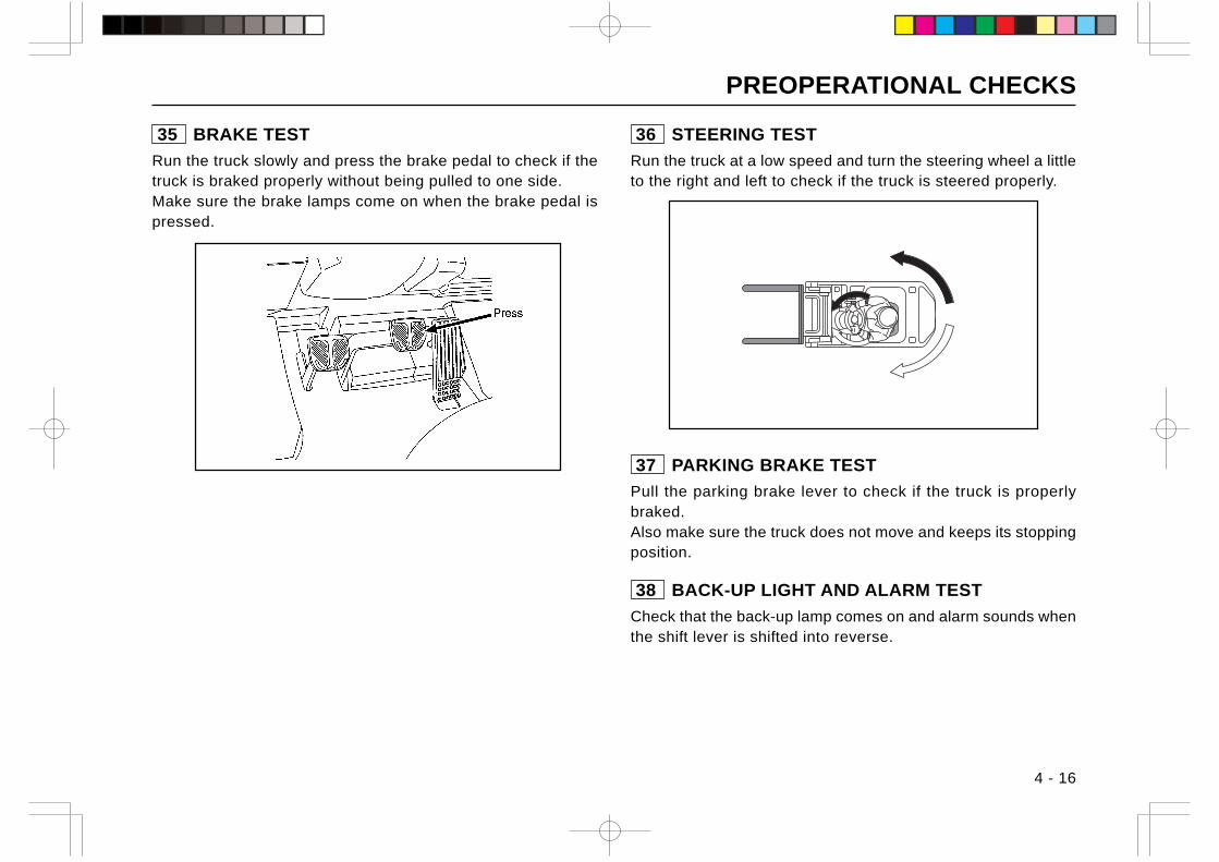
PREOPERATIONAL CHECKS
4 - 16
36 STEERING TEST
Run the truck at a low speed and turn the steering wheel a littleto the right and left to check if the truck is steered properly.
37 PARKING BRAKE TEST
Pull the parking brake lever to check if the truck is properlybraked.Also make sure the truck does not move and keeps its stoppingposition.
38 BACK-UP LIGHT AND ALARM TEST
Check that the back-up lamp comes on and alarm sounds whenthe shift lever is shifted into reverse.
35 BRAKE TEST
Run the truck slowly and press the brake pedal to check if thetruck is braked properly without being pulled to one side.Make sure the brake lamps come on when the brake pedal ispressed.
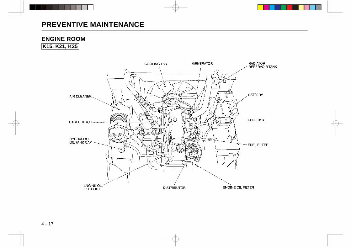
PREVENTIVE MAINTENANCE
4 - 17
ENGINE ROOMK15, K21, K25
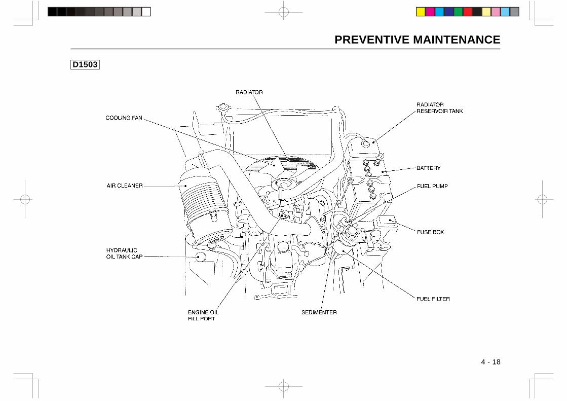
PREVENTIVE MAINTENANCE
D1503
4 - 18
」
||
~
COOLlNG FAN
AIR CLEANER
HYDRAULlC
OIL TANKCAP
ENGINE 01しFILL PORT
RADIATOR
fh v
fh y
SEDIMENTER
| ・・・・・・・・I I 圃 L
FUEL PUMP
FUEL FILTER
n==
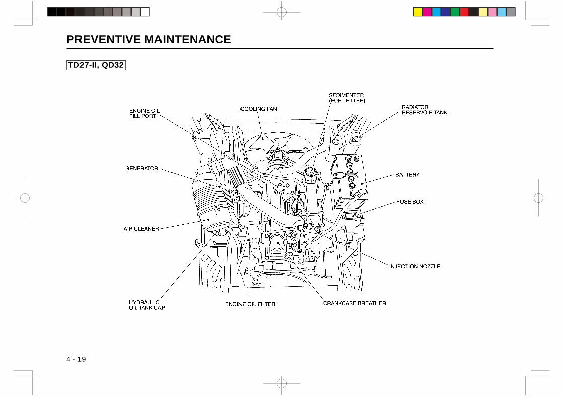
PREVENTIVE MAINTENANCE
4 - 19
TD27-II, QD32
」
十
~
ENGINE OIL FILL PORT
GENERATOR
AIR CLEANER
HYDRAULlC OIL TANKCAP
ENGINE OIL FILTER
fh v
fh y
SEDIMENTER (FUEL FILTER)
CRANKCASE BREATHER
| ・・・・・・・・I I 圃
RADIATOR RESERVOIR TANK
BATTERY
FUSE BOX
INJECTION NOZZLE
L
十
n==
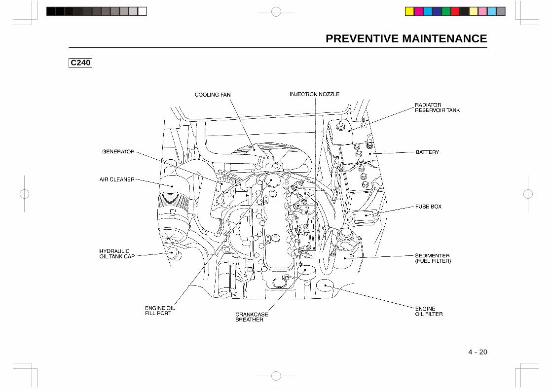
PREVENTIVE MAINTENANCE
4 - 20
C240
」
||
GENERATOR
~
ENGINE OIL FILL PORT
COOLlNG FAN
CRANKCASE BREATHER
fh v
fh y
| ・・・・・・・・I I 圃
RADIATOR RESERVOIR TANK
BATTERY
一一一嶋 SEDIMENTER(FUEL FILTER)
ENGINE OIL FILTER
L
n==
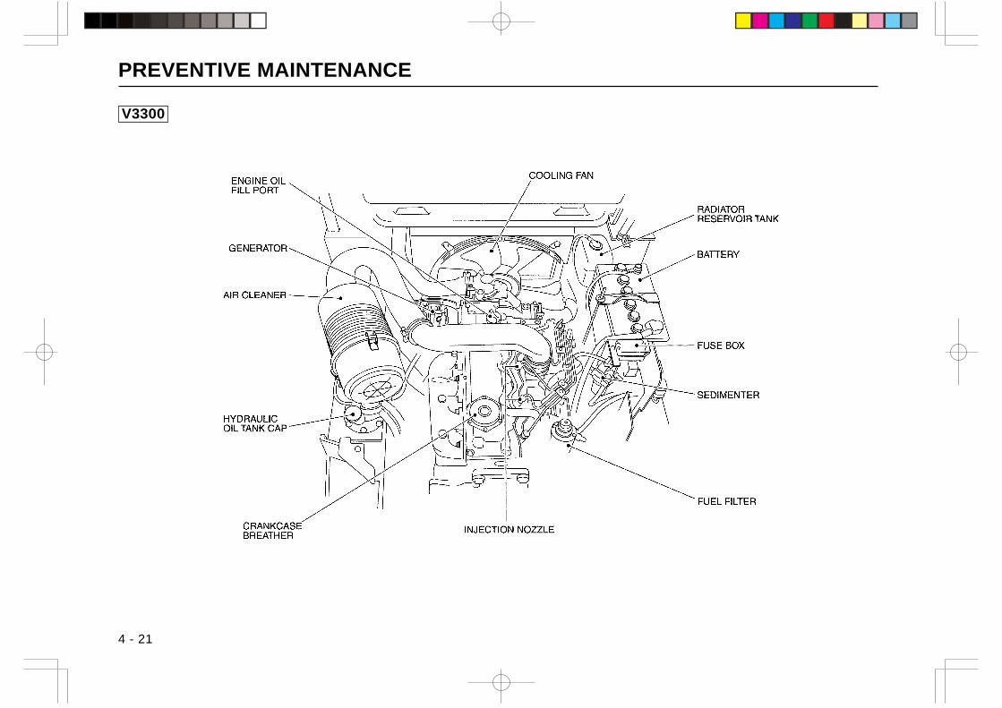
PREVENTIVE MAINTENANCE
4 - 21
V3300
」
| |
~
ENGINE OIL FILL PORT
GENERATOR
CRANKCASE BREATHER
fh v
INJECTION NOZZLE
fh y
| ・・・・・・・・I I 圃 L
FUEL FILTER
n==
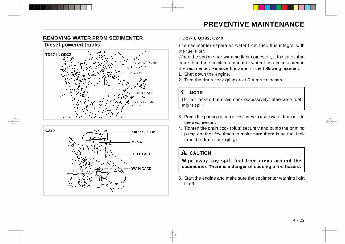
PREVENTIVE MAINTENANCE
4 - 22
TD27-II, QD32, C240
The sedimenter separates water from fuel. It is integral withthe fuel filter.When the sedimenter warning light comes on, it indicates thatmore than the specified amount of water has accumulated inthe sedimenter. Remove the water in the following manner:1. Shut down the engine.2. Turn the drain cock (plug) 4 or 5 turns to loosen it.
NOTE
Do not loosen the drain cock excessively; otherwise fuelmight spill.
3. Pump the priming pump a few times to drain water from insidethe sedimenter.
4. Tighten the drain cock (plug) securely and pump the primingpump another few times to make sure there is no fuel leakfrom the drain cock (plug) .
CAUTION
Wipe away any spilt fuel from areas around thesedimenter. There is a danger of causing a fire hazard.
5. Start the engine and make sure the sedimenter warning lightis off.
REMOVING WATER FROM SEDIMENTER Diesel-powered trucks
DRAIN COCK
PRIMING PUMP
COVER
FILTER CASE
C240
TD27-II, QD32
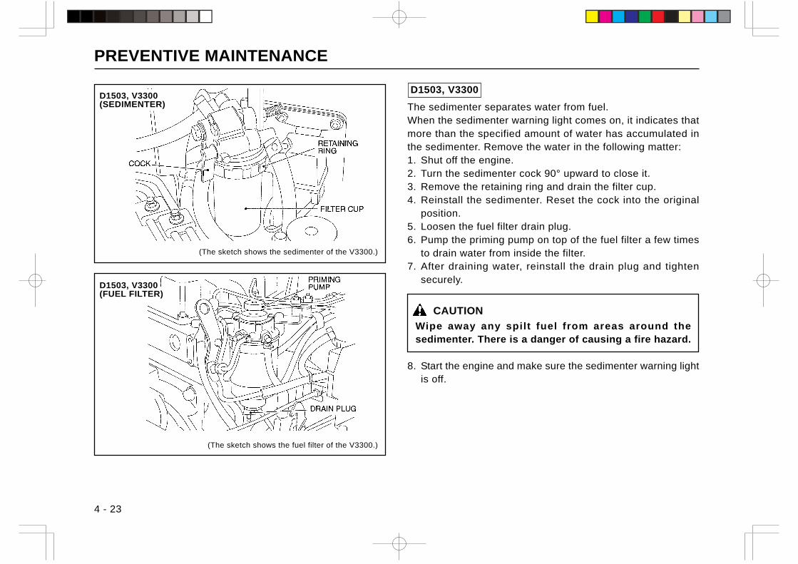
PREVENTIVE MAINTENANCE
4 - 23
D1503, V3300(FUEL FILTER)
D1503, V3300
The sedimenter separates water from fuel.When the sedimenter warning light comes on, it indicates thatmore than the specified amount of water has accumulated inthe sedimenter. Remove the water in the following matter:1. Shut off the engine.2. Turn the sedimenter cock 90° upward to close it.3. Remove the retaining ring and drain the filter cup.4. Reinstall the sedimenter. Reset the cock into the original
position.5. Loosen the fuel filter drain plug.6. Pump the priming pump on top of the fuel filter a few times
to drain water from inside the filter.7. After draining water, reinstall the drain plug and tighten
securely.
CAUTION
Wipe away any spilt fuel from areas around thesedimenter. There is a danger of causing a fire hazard.
8. Start the engine and make sure the sedimenter warning lightis off.
D1503, V3300(SEDIMENTER)
(The sketch shows the sedimenter of the V3300.)
(The sketch shows the fuel filter of the V3300.)
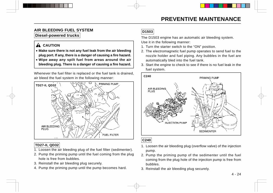
PREVENTIVE MAINTENANCE
4 - 24
AIR BLEEDING FUEL SYSTEM Diesel-powered trucks
CAUTION
• Make sure there is not any fuel leak from the air bleedingplug port. If any, there is a danger of causing a fire hazard.
• Wipe away any spilt fuel from areas around the airbleeding plug. There is a danger of causing a fire hazard.
Whenever the fuel filter is replaced or the fuel tank is drained,air bleed the fuel system in the following manner:
TD27-II, QD321. Loosen the air bleeding plug of the fuel filter (sedimenter).2. Pump the priming pump until the fuel coming from the plug
hole is free from bubbles.3. Reinstall the air bleeding plug securely.4. Pump the priming pump until the pump becomes hard.
C240
C240
1. Loosen the air bleeding plug (overflow valve) of the injectionpump.
2. Pump the priming pump of the sedimenter until the fuelcoming from the plug hole of the injection pump is free frombubbles.
3. Reinstall the air bleeding plug securely.
D1503
The D1503 engine has an automatic air bleeding system.Use it in the following manner:1. Turn the starter switch to the “ON” position.2. The electromagnetic fuel pump operates to send fuel to the
nozzle holder and fuel piping. Any bubbles in the fuel areautomatically bled into the fuel tank.
3. Start the engine to check to see if there is no fuel leak in thefuel system.
TD27-II, QD32
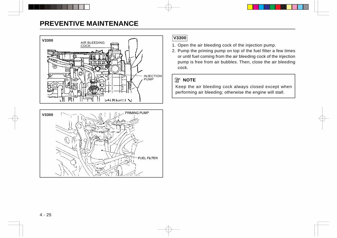
PREVENTIVE MAINTENANCE
4 - 25
V3300
V3300AIR BLEEDINGCOCK
INJECTIONPUMP
V3300
1. Open the air bleeding cock of the injection pump.2. Pump the priming pump on top of the fuel filter a few times
or until fuel coming from the air bleeding cock of the injectionpump is free from air bubbles. Then, close the air bleedingcock.
NOTE
Keep the air bleeding cock always closed except whenperforming air bleeding; otherwise the engine will stall.
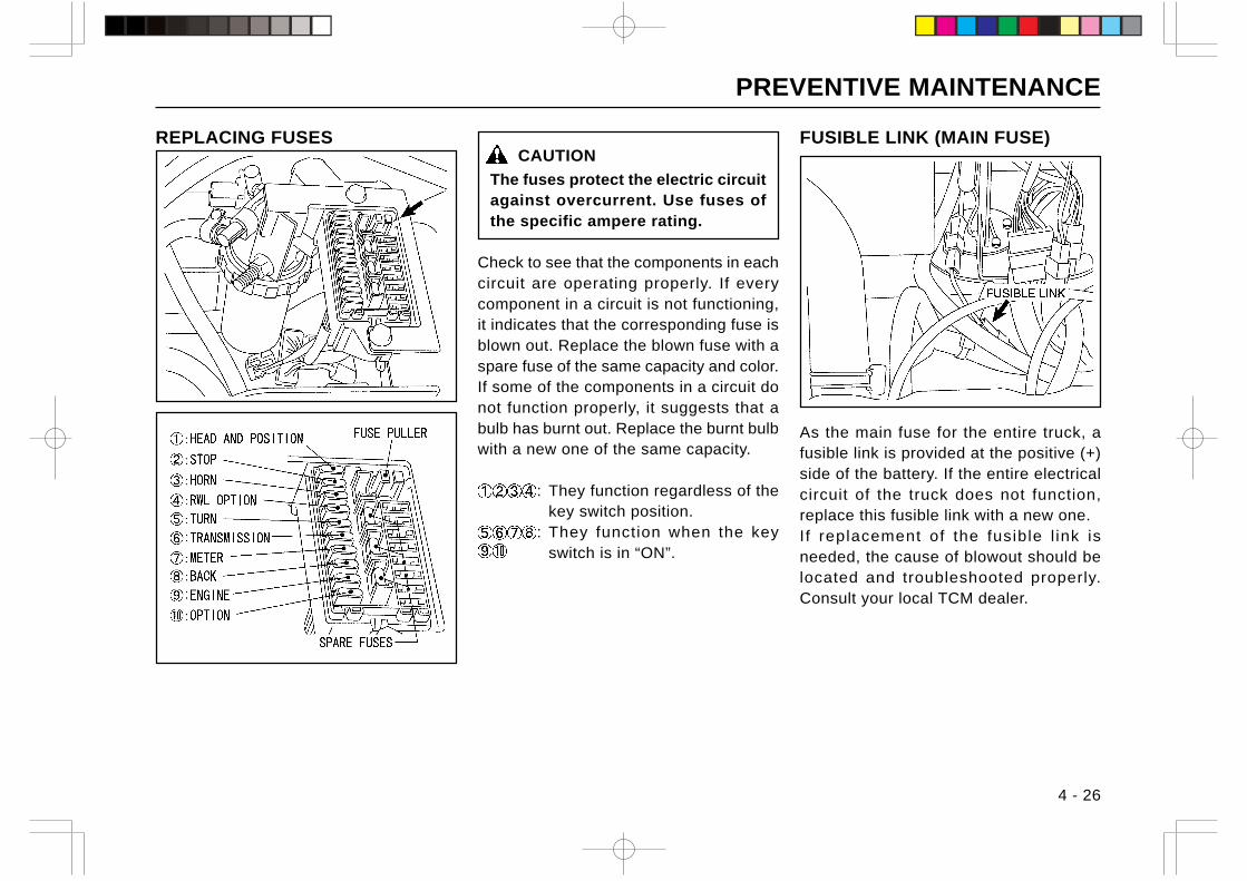
PREVENTIVE MAINTENANCE
4 - 26
CAUTION
The fuses protect the electric circuitagainst overcurrent. Use fuses ofthe specific ampere rating.
Check to see that the components in eachcircuit are operating properly. If everycomponent in a circuit is not functioning,it indicates that the corresponding fuse isblown out. Replace the blown fuse with aspare fuse of the same capacity and color.If some of the components in a circuit donot function properly, it suggests that abulb has burnt out. Replace the burnt bulbwith a new one of the same capacity.
: They function regardless of thekey switch position.
: They function when the keyswitch is in “ON”.
FUSIBLE LINK (MAIN FUSE)
As the main fuse for the entire truck, afusible link is provided at the positive (+)side of the battery. If the entire electricalcircuit of the truck does not function,replace this fusible link with a new one.If replacement of the fusible l ink isneeded, the cause of blowout should belocated and troubleshooted properly.Consult your local TCM dealer.
REPLACING FUSES
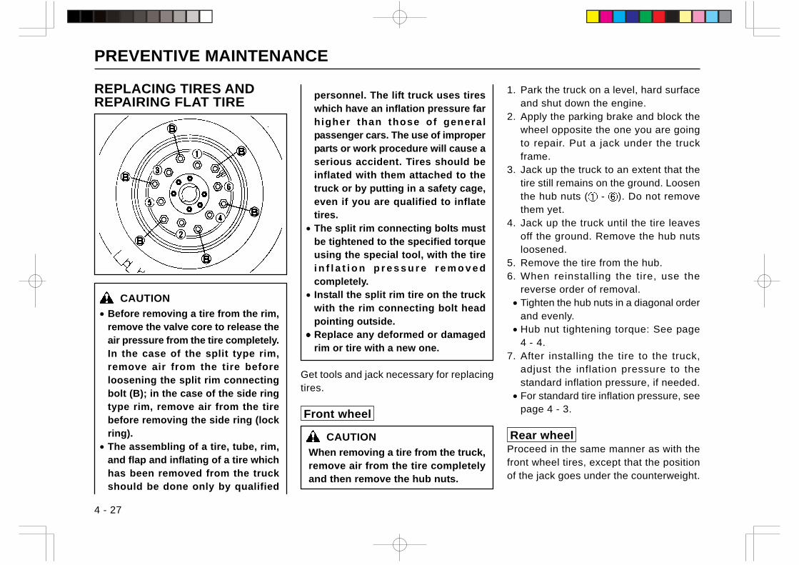
PREVENTIVE MAINTENANCE
4 - 27
REPLACING TIRES ANDREPAIRING FLAT TIRE
CAUTION
• Before removing a tire from the rim,remove the valve core to release theair pressure from the tire completely.In the case of the split type rim,remove air from the tire beforeloosening the split rim connectingbolt (B); in the case of the side ringtype rim, remove air from the tirebefore removing the side ring (lockring).
• The assembling of a tire, tube, rim,and flap and inflating of a tire whichhas been removed from the truckshould be done only by qualified
personnel. The lift truck uses tireswhich have an inflation pressure farhigher than those of generalpassenger cars. The use of improperparts or work procedure will cause aserious accident. Tires should beinflated with them attached to thetruck or by putting in a safety cage,even if you are qualified to inflatetires.
• The split rim connecting bolts mustbe tightened to the specified torqueusing the special tool, with the tirei n f l a t i o n p r e s s u r e r e m o v e dcompletely.
• Install the split rim tire on the truckwith the rim connecting bolt headpointing outside.
••••• Replace any deformed or damagedrim or tire with a new one.
Get tools and jack necessary for replacingtires.
Front wheel
CAUTION
When removing a tire from the truck,remove air from the tire completelyand then remove the hub nuts.
1. Park the truck on a level, hard surfaceand shut down the engine.
2. Apply the parking brake and block thewheel opposite the one you are goingto repair. Put a jack under the truckframe.
3. Jack up the truck to an extent that thetire still remains on the ground. Loosenthe hub nuts ( - ). Do not removethem yet.
4. Jack up the truck until the tire leavesoff the ground. Remove the hub nutsloosened.
5. Remove the tire from the hub.6. When reinstalling the tire, use the
reverse order of removal. • Tighten the hub nuts in a diagonal order
and evenly. • Hub nut tightening torque: See page
4 - 4.7. After installing the tire to the truck,
adjust the inflation pressure to thestandard inflation pressure, if needed.
• For standard tire inflation pressure, seepage 4 - 3.
Rear wheelProceed in the same manner as with thefront wheel tires, except that the positionof the jack goes under the counterweight.
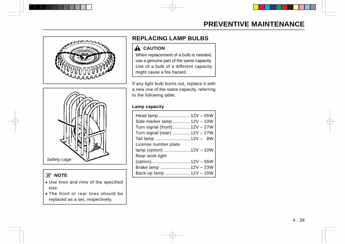
PREVENTIVE MAINTENANCE
4 - 28
NOTE
• Use tires and rims of the specifiedsize.
• The front or rear tires should bereplaced as a set, respectively.
REPLACING LAMP BULBS
CAUTION
When replacement of a bulb is needed,use a genuine part of the same capacity.Use of a bulb of a different capacitymight cause a fire hazard.
If any light bulb burns out, replace it witha new one of the same capacity, referringto the following table:
Lamp capacity
Head lamp ......................... 12V – 55WSide marker lamp .............. 12V – 10WTurn signal (front) .............. 12V – 27WTurn signal (rear) .............. 12V – 27WTail lamp ............................ 12V – 8WLicense number platelamp (option) ..................... 12V – 10WRear work light(option)............................... 12V – 55WBrake lamp ........................ 12V – 23WBack-up lamp .................... 12V – 10W
Safety cage
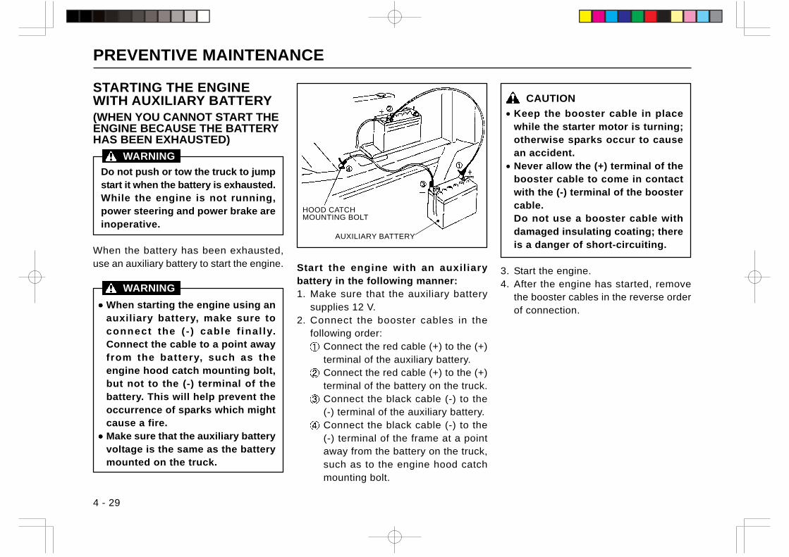
PREVENTIVE MAINTENANCE
CAUTION
• Keep the booster cable in placewhile the starter motor is turning;otherwise sparks occur to causean accident.
• Never allow the (+) terminal of thebooster cable to come in contactwith the (-) terminal of the boostercable.Do not use a booster cable withdamaged insulating coating; thereis a danger of short-circuiting.
3. Start the engine.4. After the engine has started, remove
the booster cables in the reverse orderof connection.
4 - 29
STARTING THE ENGINEWITH AUXILIARY BATTERY(WHEN YOU CANNOT START THEENGINE BECAUSE THE BATTERYHAS BEEN EXHAUSTED)
Do not push or tow the truck to jumpstart it when the battery is exhausted.While the engine is not running,power steering and power brake areinoperative.
When the battery has been exhausted,use an auxiliary battery to start the engine.
••••• When starting the engine using anauxiliary battery, make sure toconnect the ( - ) cable f inal ly.Connect the cable to a point awayfrom the battery, such as theengine hood catch mounting bolt,but not to the (-) terminal of thebattery. This will help prevent theoccurrence of sparks which mightcause a fire.
••••• Make sure that the auxiliary batteryvoltage is the same as the batterymounted on the truck.
Start the engine with an auxiliarybattery in the following manner:1. Make sure that the auxiliary battery
supplies 12 V.2. Connect the booster cables in the
following order:Connect the red cable (+) to the (+)terminal of the auxiliary battery.Connect the red cable (+) to the (+)terminal of the battery on the truck.Connect the black cable (-) to the(-) terminal of the auxiliary battery.Connect the black cable (-) to the(-) terminal of the frame at a pointaway from the battery on the truck,such as to the engine hood catchmounting bolt.
WARNING
HOOD CATCHMOUNTING BOLT
AUXILIARY BATTERY
WARNING
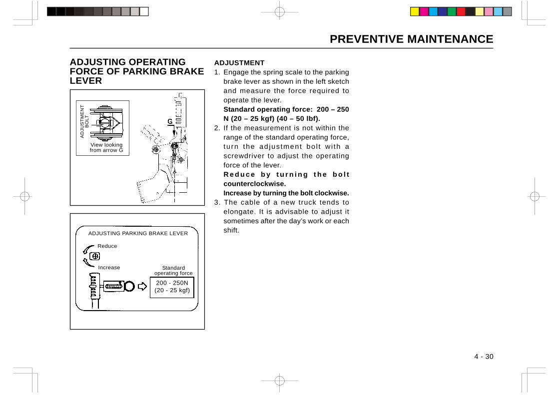
PREVENTIVE MAINTENANCE
4 - 30
ADJUSTING OPERATINGFORCE OF PARKING BRAKELEVER
ADJUSTMENT1. Engage the spring scale to the parking
brake lever as shown in the left sketchand measure the force required tooperate the lever.Standard operating force: 200 – 250N (20 – 25 kgf) (40 – 50 lbf).
2. If the measurement is not within therange of the standard operating force,tu rn the ad jus tment bo l t w i th ascrewdriver to adjust the operatingforce of the lever.R e d u c e b y t u r n i n g t h e b o l tcounterclockwise.Increase by turning the bolt clockwise.
3. The cable of a new truck tends toelongate. It is advisable to adjust itsometimes after the day’s work or eachshift.
AD
JUS
TM
EN
TB
OLT
View lookingfrom arrow G
ADJUSTING PARKING BRAKE LEVER
Reduce
Increase Standardoperating force
200 - 250N(20 - 25 kgf)
PERIODIC INSPECTION
4 - 31
Just as your body needs to undergo physical examinations,your truck needs periodical checks and maintenance.When the truck appears to be in good condition, checks andmaintenance are likely to be neglected. But early discovery oftrouble which may decrease truck efficiency and immediatecorrection, will greatly increase the working capacity of the truck,bring about greater productivity, prolong its life span and makeit more economical.
Preoperational checks, the addition of oil, grease and fuel, andcleaning of filter elements should be carried out by the customerand other complicated checks and maintenance should be leftto your TCM dealer. If enough knowledge, special tools orequipment is not available, personal injury could occur duringchecking or servicing. In this manual, the periodic inspectionintervals are indicated as the number of months (years) as wellas operating hours. Every one month of operation is calculatedas 200 operating hours.
CAUTION
Be sure to read “INSPECTION AND SERVICE” in Chapter1. “SAFETY” before checking or servicing the truck.
PERIODICAL REPLACEMENT OF SAFETYPARTSIn order to perform safe operation, the importance of preventivemaintenance of the truck cannot be overemphasized.Especially, the parts listed in the table below must be replacedperiodically since they are the most important parts for safetyof the truck and operator.Moreover these safety parts are liable to be damaged anddeteriorated in the course of time, and it is difficult to determineby ordinary maintenance whether they are beyond theirrespective service limits or not. The safety parts must bereplaced with new ones when their respective service limitshave been reached, even if their appearances are good.
NOTE
The safety parts are, however, not the objects of warrantyclaim.
Recommended Name of safety parts replacement
interval (year)
1 Master cylinder and wheel cylindercups and dust seals 1
2 Power steering hose 2
3 Reserve tank tubing 2 – 4
4 Fuel hose 2 – 4
5 Torque converter rubber hose 2
6 Rubber parts inside power steeringunit 2
7 Lift chain 2 – 4
8 Load handling means hose 1 – 2
PERIODIC INSPECTION
4 - 32
MONTHLY (200 OPERATING HOURS)CHECKS
Perform preoperational checks in addition to the following.
The adjustment and replacement of components and parts listedas monthly check items are difficult and need a sufficienttechnical knowledge and special tools.
Items to be checked
• Air cleaner – Clean element.• Engine cylinder head bolt – Retighten (gas-powered trucks,
for the first time only).• Engine oil – Change [1 week (50 operating hours) for the
first time only].• Engine oil filter – Change (first time only).• Fuel filter – Check for clogging (gas-powered trucks).• Cooling system rubber hose – Check for deterioration.• Radiator cap – Check for function and proper installation.• Oil clutch – Check oil level in the tank (trucks with optional
oil clutch).• Torque converter inline filler – Change ( T type , for first
time only).• Front axle mount bolt – Check for looseness.• Front axle – Check for deformation, cracks, or damage.• Tire tread – Check for wear or foreign matter.• Wheel bearing – Check for looseness or noise.• Rear axle – Check for deformation, cracks or damage.• Steering gear box – Check for loose mounting bolt.• Steering gear box – Check for oil leak.• Rod, arm and king pin – Check for looseness, warping or
damage.• Rear axle – Check for bend, damage or installation.• Steering cylinder – Check for loose mounting part or joint.• Brake piping – Check for the entrance of air.• Brake system rods and parking brake cables – Check for
proper operation and looseness.
(to be continued)
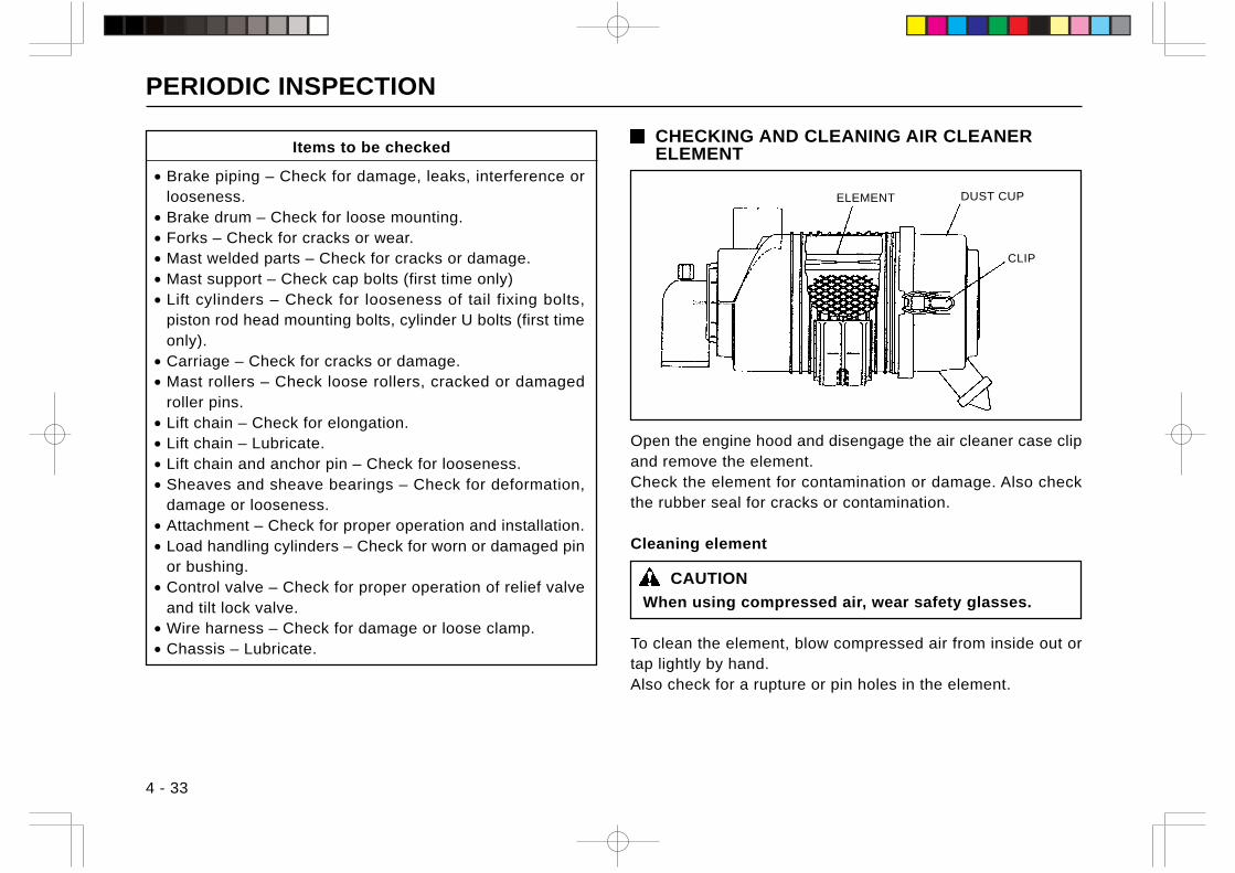
PERIODIC INSPECTION
4 - 33
Items to be checked
• Brake piping – Check for damage, leaks, interference orlooseness.
• Brake drum – Check for loose mounting.• Forks – Check for cracks or wear.• Mast welded parts – Check for cracks or damage.• Mast support – Check cap bolts (first time only)• Lift cylinders – Check for looseness of tail fixing bolts,
piston rod head mounting bolts, cylinder U bolts (first timeonly).
• Carriage – Check for cracks or damage.• Mast rollers – Check loose rollers, cracked or damaged
roller pins.• Lift chain – Check for elongation.• Lift chain – Lubricate.• Lift chain and anchor pin – Check for looseness.• Sheaves and sheave bearings – Check for deformation,
damage or looseness.• Attachment – Check for proper operation and installation.• Load handling cylinders – Check for worn or damaged pin
or bushing.• Control valve – Check for proper operation of relief valve
and tilt lock valve.• Wire harness – Check for damage or loose clamp.• Chassis – Lubricate.
CHECKING AND CLEANING AIR CLEANERELEMENT
Open the engine hood and disengage the air cleaner case clipand remove the element.Check the element for contamination or damage. Also checkthe rubber seal for cracks or contamination.
Cleaning element
CAUTION
When using compressed air, wear safety glasses.
To clean the element, blow compressed air from inside out ortap lightly by hand.Also check for a rupture or pin holes in the element.
CLIP
DUST CUPELEMENT
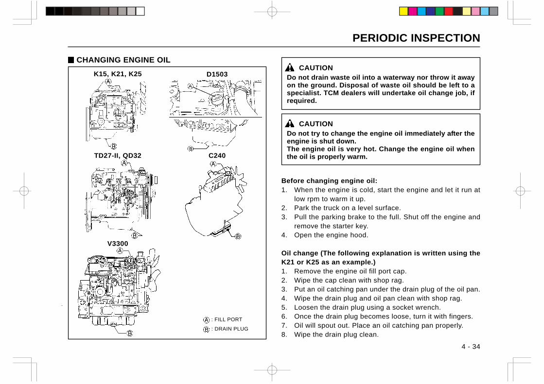
PERIODIC INSPECTION
4 - 34
CAUTIONDo not drain waste oil into a waterway nor throw it awayon the ground. Disposal of waste oil should be left to aspecialist. TCM dealers will undertake oil change job, ifrequired.
CAUTIONDo not try to change the engine oil immediately after theengine is shut down.The engine oil is very hot. Change the engine oil whenthe oil is properly warm.
Before changing engine oil:1. When the engine is cold, start the engine and let it run at
low rpm to warm it up.2. Park the truck on a level surface.3. Pull the parking brake to the full. Shut off the engine and
remove the starter key.4. Open the engine hood.
Oil change (The following explanation is written using theK21 or K25 as an example.)1. Remove the engine oil fill port cap.2. Wipe the cap clean with shop rag.3. Put an oil catching pan under the drain plug of the oil pan.4. Wipe the drain plug and oil pan clean with shop rag.5. Loosen the drain plug using a socket wrench.6. Once the drain plug becomes loose, turn it with fingers.7. Oil will spout out. Place an oil catching pan properly.8. Wipe the drain plug clean.
CHANGING ENGINE OIL
: FILL PORT
: DRAIN PLUG
K15, K21, K25
V3300
C240TD27-II, QD32
D1503
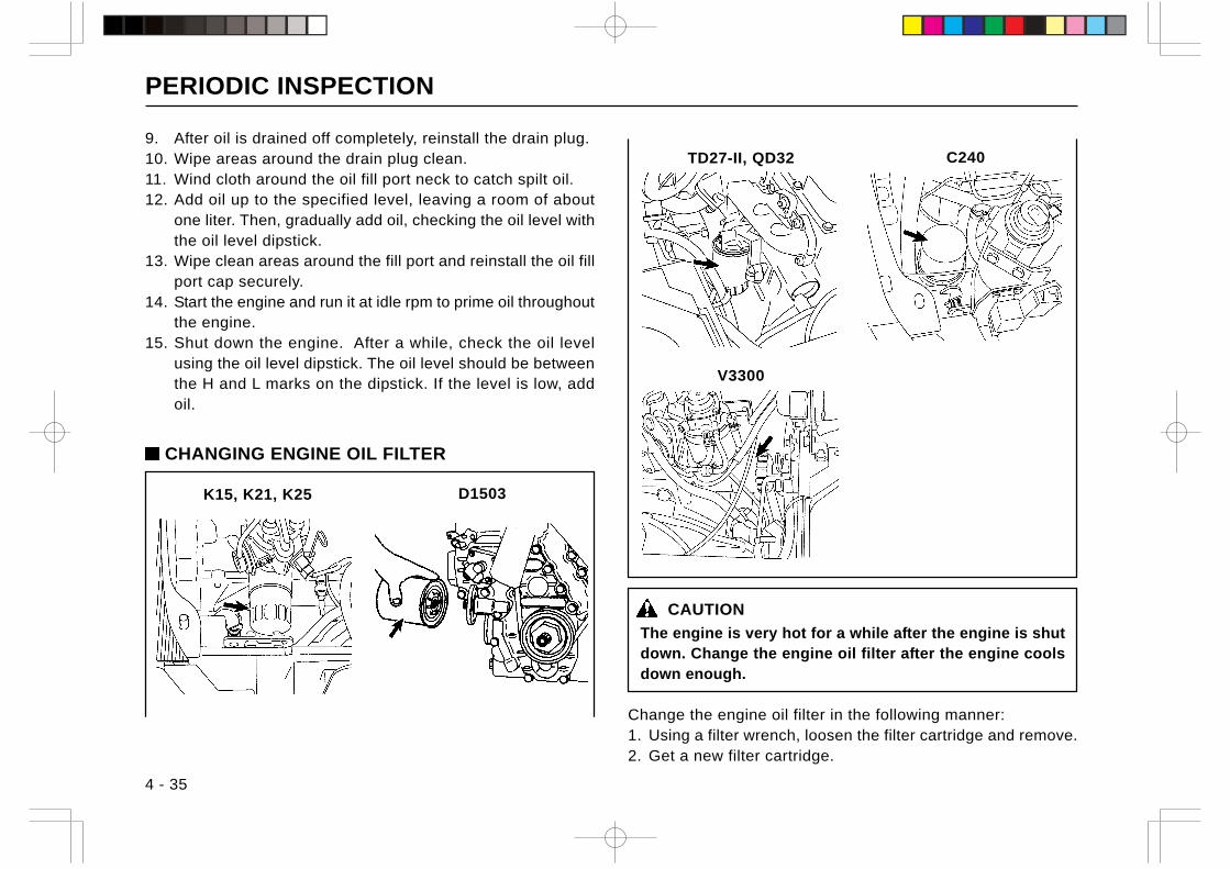
PERIODIC INSPECTION
4 - 35
9. After oil is drained off completely, reinstall the drain plug.10. Wipe areas around the drain plug clean.11. Wind cloth around the oil fill port neck to catch spilt oil.12. Add oil up to the specified level, leaving a room of about
one liter. Then, gradually add oil, checking the oil level withthe oil level dipstick.
13. Wipe clean areas around the fill port and reinstall the oil fillport cap securely.
14. Start the engine and run it at idle rpm to prime oil throughoutthe engine.
15. Shut down the engine. After a while, check the oil levelusing the oil level dipstick. The oil level should be betweenthe H and L marks on the dipstick. If the level is low, addoil.
CAUTION
The engine is very hot for a while after the engine is shutdown. Change the engine oil filter after the engine coolsdown enough.
Change the engine oil filter in the following manner:1. Using a filter wrench, loosen the filter cartridge and remove.2. Get a new filter cartridge.
K15, K21, K25
V3300
C240TD27-II, QD32
CHANGING ENGINE OIL FILTER
D1503
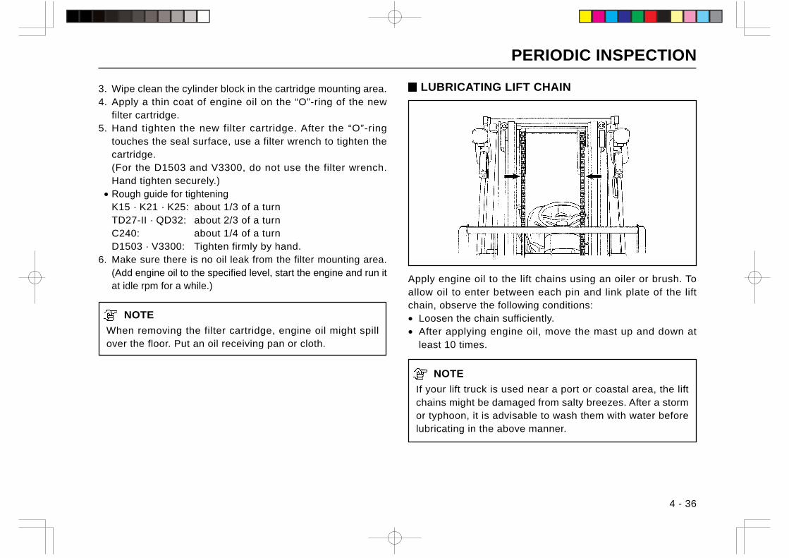
PERIODIC INSPECTION
4 - 36
3. Wipe clean the cylinder block in the cartridge mounting area.4. Apply a thin coat of engine oil on the “O”-ring of the new
filter cartridge.5. Hand tighten the new filter cartridge. After the “O”-ring
touches the seal surface, use a filter wrench to tighten thecartridge.(For the D1503 and V3300, do not use the filter wrench.Hand tighten securely.)
• Rough guide for tighteningK15 · K21 · K25: about 1/3 of a turnTD27-II · QD32: about 2/3 of a turnC240: about 1/4 of a turnD1503 · V3300: Tighten firmly by hand.
6. Make sure there is no oil leak from the filter mounting area.(Add engine oil to the specified level, start the engine and run itat idle rpm for a while.)
NOTE
When removing the filter cartridge, engine oil might spillover the floor. Put an oil receiving pan or cloth.
Apply engine oil to the lift chains using an oiler or brush. Toallow oil to enter between each pin and link plate of the liftchain, observe the following conditions:• Loosen the chain sufficiently.• After applying engine oil, move the mast up and down at
least 10 times.
NOTE
If your lift truck is used near a port or coastal area, the liftchains might be damaged from salty breezes. After a stormor typhoon, it is advisable to wash them with water beforelubricating in the above manner.
LUBRICATING LIFT CHAIN
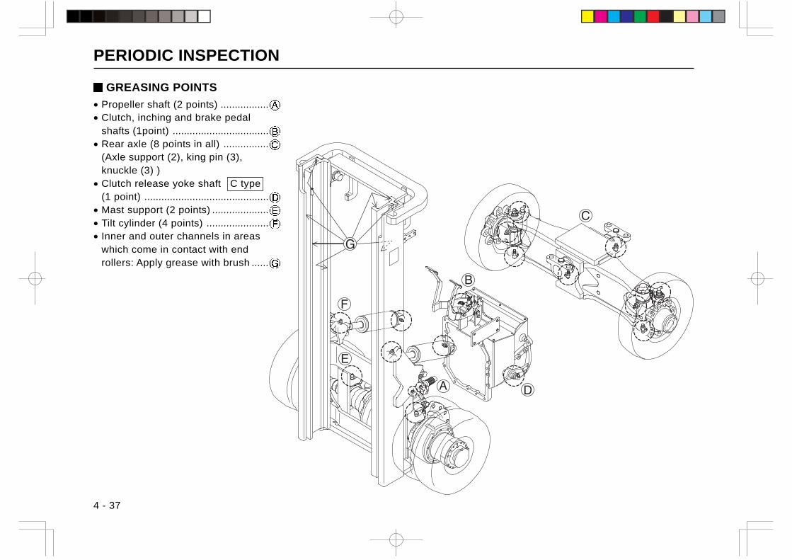
PERIODIC INSPECTION
4 - 37
GREASING POINTS
• Propeller shaft (2 points) .................• Clutch, inching and brake pedal
shafts (1point) ..................................• Rear axle (8 points in all) ................
(Axle support (2), king pin (3),knuckle (3) )
• Clutch release yoke shaft C type(1 point) ............................................
• Mast support (2 points) ....................• Tilt cylinder (4 points) ......................• Inner and outer channels in areas
which come in contact with endrollers: Apply grease with brush ......
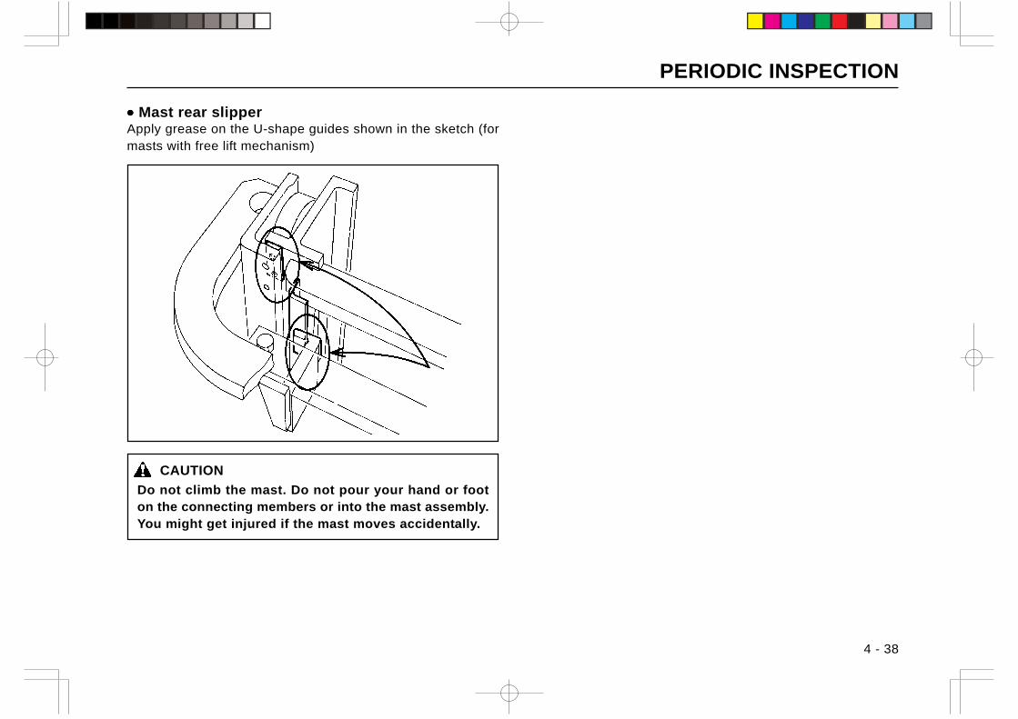
PERIODIC INSPECTION
4 - 38
••••• Mast rear slipperApply grease on the U-shape guides shown in the sketch (formasts with free lift mechanism)
CAUTION
Do not climb the mast. Do not pour your hand or footon the connecting members or into the mast assembly.You might get injured if the mast moves accidentally.
PERIODIC INSPECTION
4 - 39
Items to be checked
• Crankcase – Check the air breather for contamination andclean if necessary
• Engine oil filter – Change• Fuel filter – Clean (gas-powered trucks)• Fuel filter – Change (diesel-powered trucks)• Carburator – Check linkage for looseness or contamination.• Fuel tank – Drain water (diesel-powered trucks).• Cooling water – Change (every 2 years for trucks using
LLC).• Fork stopper pins – Check for damage or wear.• Distributor – Check for cracked cap (gas-powered trucks)• Spark plug – Adjust the gap (gas-powered trucks).• Spark plug – Clean (gas-powered trucks).• Distributor – Check the air gap between rotor and stator
and the general condition of rotor (gas-powered trucks).• Distributor shaft – Lubricate (gas-powered trucks).• Starter pinion gear – Check for proper engagement.• Charger – Check for proper operation.• Battery – Check the specific gravity of the electrolyte.• Electrical wiring – Check for loose connections.
3 MONTHS (600 OPERATING HOURS)CHECKS
Perform the following checks in addition to preoperationalchecks and one month (200 operating hours) checks.
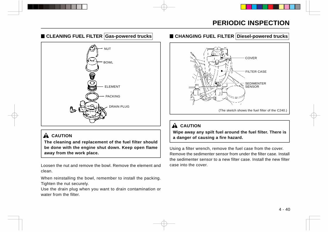
PERIODIC INSPECTION
4 - 40
CLEANING FUEL FILTER Gas-powered trucks
CAUTION
The cleaning and replacement of the fuel filter shouldbe done with the engine shut down. Keep open flameaway from the work place.
Loosen the nut and remove the bowl. Remove the element andclean.
When reinstalling the bowl, remember to install the packing.Tighten the nut securely.Use the drain plug when you want to drain contamination orwater from the filter.
CHANGING FUEL FILTER Diesel-powered trucks
CAUTION
Wipe away any spilt fuel around the fuel filter. There isa danger of causing a fire hazard.
Using a filter wrench, remove the fuel case from the cover.Remove the sedimenter sensor from under the filter case. Installthe sedimenter sensor to a new filter case. Install the new filtercase into the cover.
SEDIMENTERSENSOR
COVER
FILTER CASE
(The sketch shows the fuel filter of the C240.)DRAIN PLUG
NUT
BOWL
ELEMENT
PACKING
PERIODIC INSPECTION
4 - 41
6 MONTHS (1200 OPERATING HOURS)CHECKS
Perform the following checks in addition to daily checks, onemonth (200 operating hours) checks, and 3 months (600operating hours) checks.
Items to be checked
• Air cleaner element – Change.• Valve clearance – Check.• Blow-by gas reducing device- Check metering valve and
piping for clogging or damage.• Injection nozzle – Check injection pressure and spray
pattern.• Engine – Check ignition timing (gas-powered trucks).• Fuel tank – Clean inside.• Clutch and brake fluid – Change• Transmission oil (gear oil) – Change ( C type ).• Torque convertor oil – Change ( T type ).
• Torque converter inline filter – Change ( T type ).• Front axle – Change oil.• Wheel bearing – Disassemble and change grease.• Mast support – Check for loose cap bolt.• Lift cylinder – Check for looseness of cylinder tail fixing
bolts, piston rod head mounting bolts and cylinder fixing Ubolts and retighten where necessary.
• Hydraulic oil – Change.• Hydraulic oil tank suction strainer – Change.• Hydraulic oil tank return filter – Change.• Control valve – Measure relief pressure.• Operator’s seat – Check for damage and loose mounting
bolts.
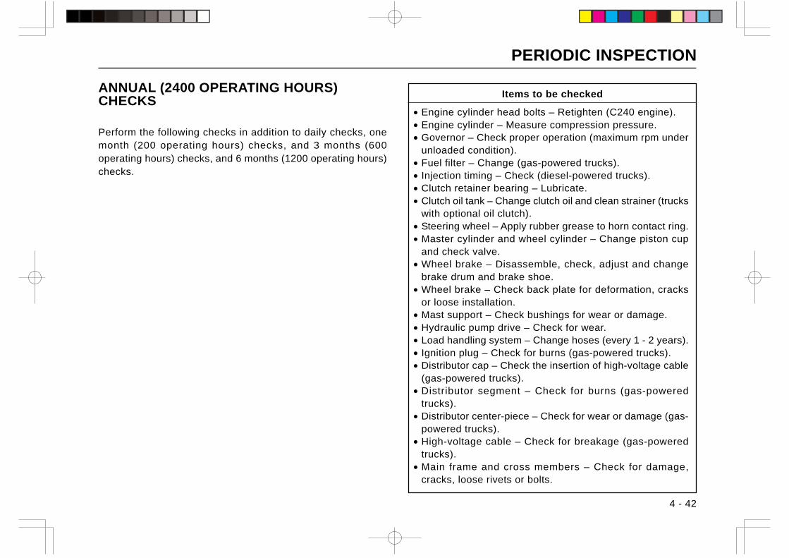
PERIODIC INSPECTION
4 - 42
ANNUAL (2400 OPERATING HOURS)CHECKS
Perform the following checks in addition to daily checks, onemonth (200 operating hours) checks, and 3 months (600operating hours) checks, and 6 months (1200 operating hours)checks.
Items to be checked
• Engine cylinder head bolts – Retighten (C240 engine).• Engine cylinder – Measure compression pressure.• Governor – Check proper operation (maximum rpm under
unloaded condition).• Fuel filter – Change (gas-powered trucks).• Injection timing – Check (diesel-powered trucks).• Clutch retainer bearing – Lubricate.• Clutch oil tank – Change clutch oil and clean strainer (trucks
with optional oil clutch).• Steering wheel – Apply rubber grease to horn contact ring.• Master cylinder and wheel cylinder – Change piston cup
and check valve.• Wheel brake – Disassemble, check, adjust and change
brake drum and brake shoe.• Wheel brake – Check back plate for deformation, cracks
or loose installation.• Mast support – Check bushings for wear or damage.• Hydraulic pump drive – Check for wear.• Load handling system – Change hoses (every 1 - 2 years).• Ignition plug – Check for burns (gas-powered trucks).• Distributor cap – Check the insertion of high-voltage cable
(gas-powered trucks).• Distributor segment – Check for burns (gas-powered
trucks).• Distributor center-piece – Check for wear or damage (gas-
powered trucks).• High-voltage cable – Check for breakage (gas-powered
trucks).• Main frame and cross members – Check for damage,
cracks, loose rivets or bolts.
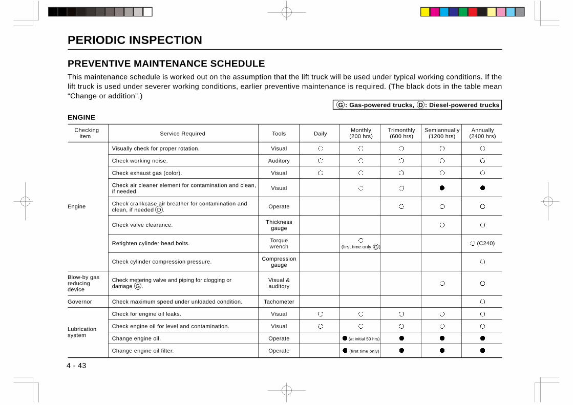
PERIODIC INSPECTION
4 - 43
PREVENTIVE MAINTENANCE SCHEDULEThis maintenance schedule is worked out on the assumption that the lift truck will be used under typical working conditions. If thelift truck is used under severer working conditions, earlier preventive maintenance is required. (The black dots in the table mean“Change or addition”.)
ENGINE
Checking Service Required Tools Daily
Monthly Trimonthly Semiannually Annually item (200 hrs) (600 hrs) (1200 hrs) (2400 hrs)
Visually check for proper rotation. Visual
Check working noise. Auditory
Check exhaust gas (color). Visual
Check air cleaner element for contamination and clean, Visualif needed.
Engine Check crankcase air breather for contamination and Operateclean, if needed D .
Check valve clearance. Thicknessgauge
Retighten cylinder head bolts. Torque (C240)wrench (first time only G )
Check cylinder compression pressure. Compressiongauge
Blow-by gas Check metering valve and piping for clogging or Visual &reducing damage G . auditorydevice
Governor Check maximum speed under unloaded condition. Tachometer
Check for engine oil leaks. Visual
Lubrication Check engine oil for level and contamination. Visual
systemChange engine oil. Operate (at initial 50 hrs)
Change engine oil filter. Operate (first time only)
G : Gas-powered trucks, D : Diesel-powered trucks
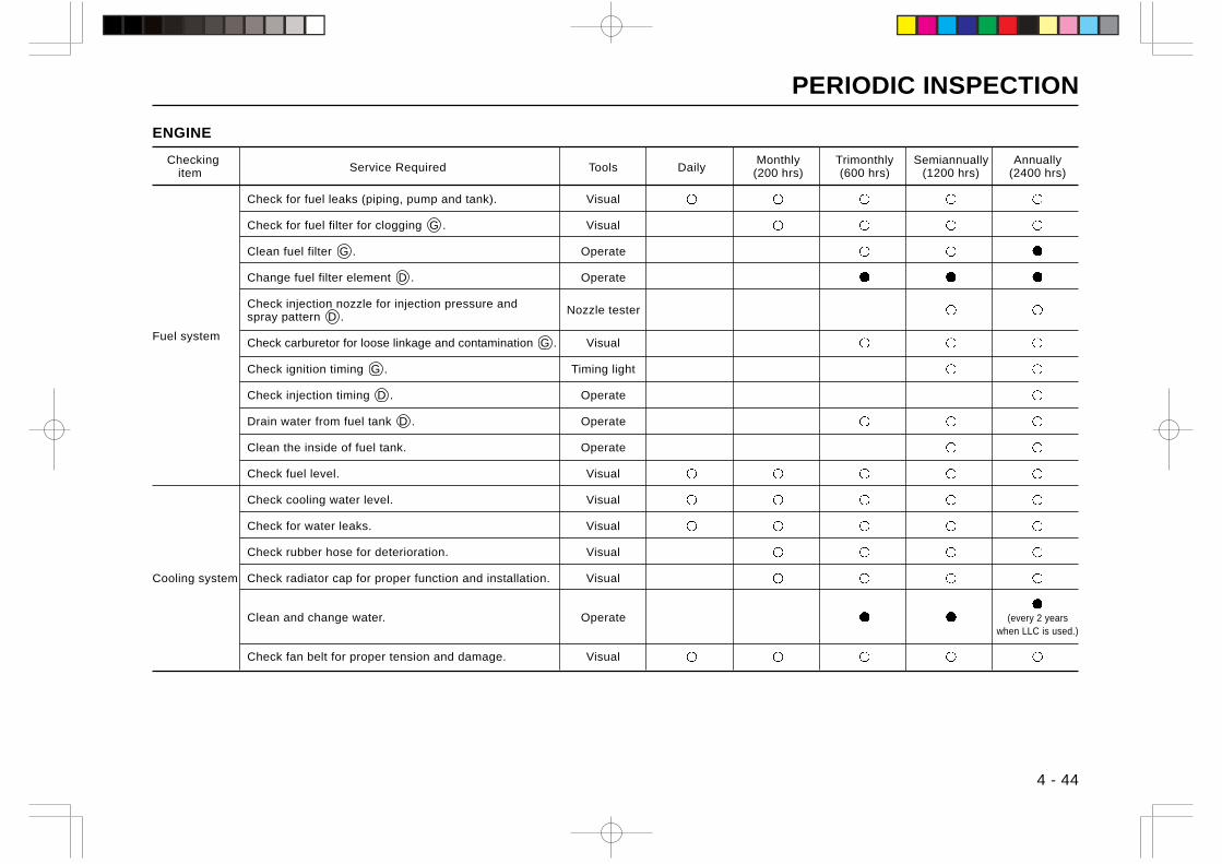
PERIODIC INSPECTION
4 - 44
ENGINE
Checking Service Required Tools Daily
Monthly Trimonthly Semiannually Annually item (200 hrs) (600 hrs) (1200 hrs) (2400 hrs)
Check for fuel leaks (piping, pump and tank). Visual
Check for fuel filter for clogging G . Visual
Clean fuel filter G . Operate
Change fuel filter element D . Operate
Check injection nozzle for injection pressure and Nozzle testerspray pattern D .
Fuel systemCheck carburetor for loose linkage and contamination G . Visual
Check ignition timing G . Timing light
Check injection timing D . Operate
Drain water from fuel tank D . Operate
Clean the inside of fuel tank. Operate
Check fuel level. Visual
Check cooling water level. Visual
Check for water leaks. Visual
Check rubber hose for deterioration. Visual
Cooling system Check radiator cap for proper function and installation. Visual
Clean and change water. Operate (every 2 yearswhen LLC is used.)
Check fan belt for proper tension and damage. Visual
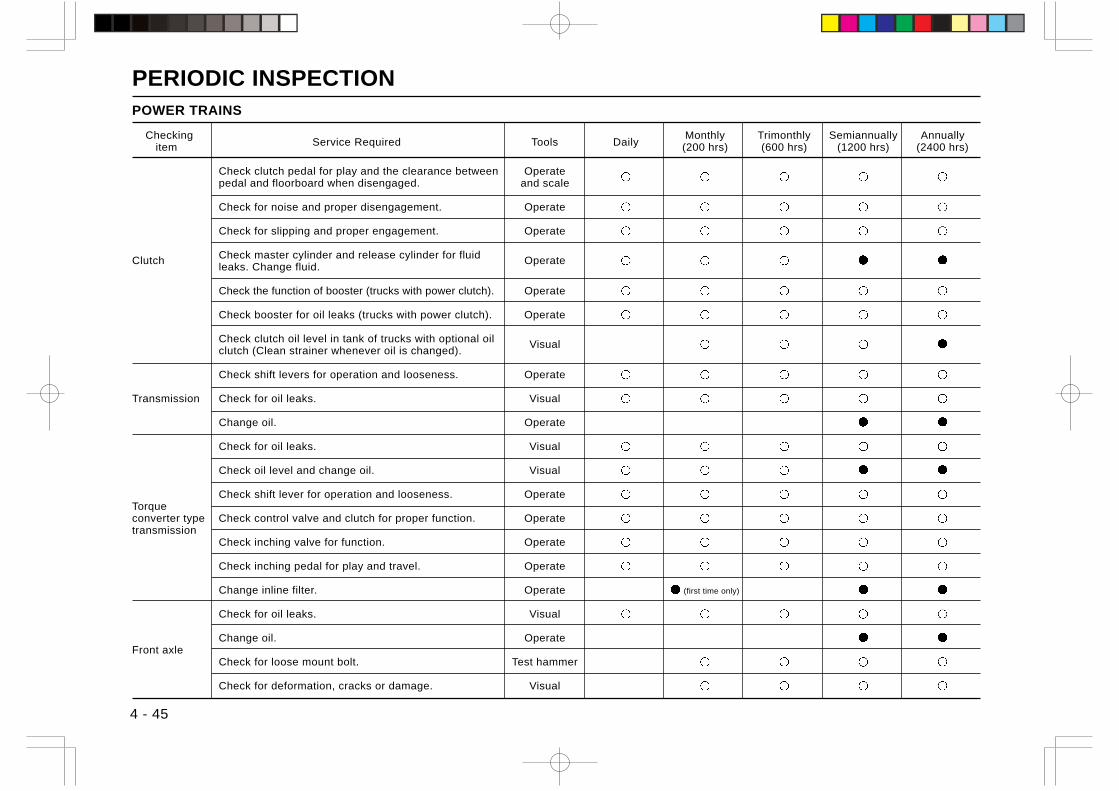
PERIODIC INSPECTION
4 - 45
POWER TRAINS
Checking Service Required Tools Daily
Monthly Trimonthly Semiannually Annually item (200 hrs) (600 hrs) (1200 hrs) (2400 hrs)
Check clutch pedal for play and the clearance between Operatepedal and floorboard when disengaged. and scale
Check for noise and proper disengagement. Operate
Check for slipping and proper engagement. Operate
Clutch Check master cylinder and release cylinder for fluid Operateleaks. Change fluid.
Check the function of booster (trucks with power clutch). Operate
Check booster for oil leaks (trucks with power clutch). Operate
Check clutch oil level in tank of trucks with optional oil Visualclutch (Clean strainer whenever oil is changed).
Check shift levers for operation and looseness. Operate
Transmission Check for oil leaks. Visual
Change oil. Operate
Check for oil leaks. Visual
Check oil level and change oil. Visual
Check shift lever for operation and looseness. OperateTorqueconverter type Check control valve and clutch for proper function. Operatetransmission
Check inching valve for function. Operate
Check inching pedal for play and travel. Operate
Change inline filter. Operate (first time only)
Check for oil leaks. Visual
Change oil. OperateFront axle
Check for loose mount bolt. Test hammer
Check for deformation, cracks or damage. Visual
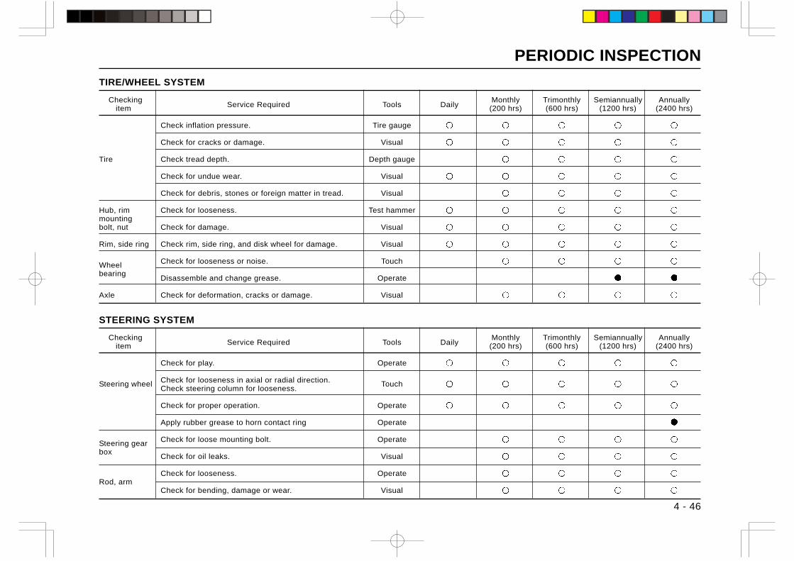
PERIODIC INSPECTION
4 - 46
TIRE/WHEEL SYSTEM
Checking Service Required Tools Daily
Monthly Trimonthly Semiannually Annually item (200 hrs) (600 hrs) (1200 hrs) (2400 hrs)
Check inflation pressure. Tire gauge
Check for cracks or damage. Visual
Tire Check tread depth. Depth gauge
Check for undue wear. Visual
Check for debris, stones or foreign matter in tread. Visual
Hub, rim Check for looseness. Test hammermountingbolt, nut Check for damage. Visual
Rim, side ring Check rim, side ring, and disk wheel for damage. Visual
Wheel Check for looseness or noise. Touch
bearingDisassemble and change grease. Operate
Axle Check for deformation, cracks or damage. Visual
STEERING SYSTEM
Checking Service Required Tools Daily
Monthly Trimonthly Semiannually Annually item (200 hrs) (600 hrs) (1200 hrs) (2400 hrs)
Check for play. Operate
Steering wheel Check for looseness in axial or radial direction. TouchCheck steering column for looseness.
Check for proper operation. Operate
Apply rubber grease to horn contact ring Operate
Steering gear Check for loose mounting bolt. Operate
boxCheck for oil leaks. Visual
Check for looseness. OperateRod, arm
Check for bending, damage or wear. Visual
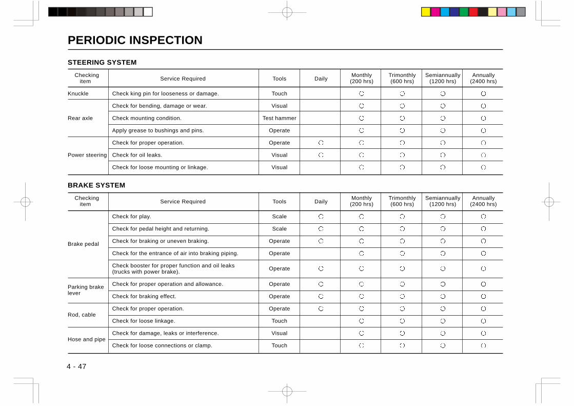
PERIODIC INSPECTION
4 - 47
STEERING SYSTEM
Checking Service Required Tools Daily
Monthly Trimonthly Semiannually Annually item (200 hrs) (600 hrs) (1200 hrs) (2400 hrs)
Knuckle Check king pin for looseness or damage. Touch
Check for bending, damage or wear. Visual
Rear axle Check mounting condition. Test hammer
Apply grease to bushings and pins. Operate
Check for proper operation. Operate
Power steering Check for oil leaks. Visual
Check for loose mounting or linkage. Visual
BRAKE SYSTEM
Checking Service Required Tools Daily
Monthly Trimonthly Semiannually Annually item (200 hrs) (600 hrs) (1200 hrs) (2400 hrs)
Check for play. Scale
Check for pedal height and returning. Scale
Brake pedal Check for braking or uneven braking. Operate
Check for the entrance of air into braking piping. Operate
Check booster for proper function and oil leaks Operate(trucks with power brake).
Parking brake Check for proper operation and allowance. Operate
leverCheck for braking effect. Operate
Check for proper operation. OperateRod, cable
Check for loose linkage. Touch
Check for damage, leaks or interference. VisualHose and pipe
Check for loose connections or clamp. Touch
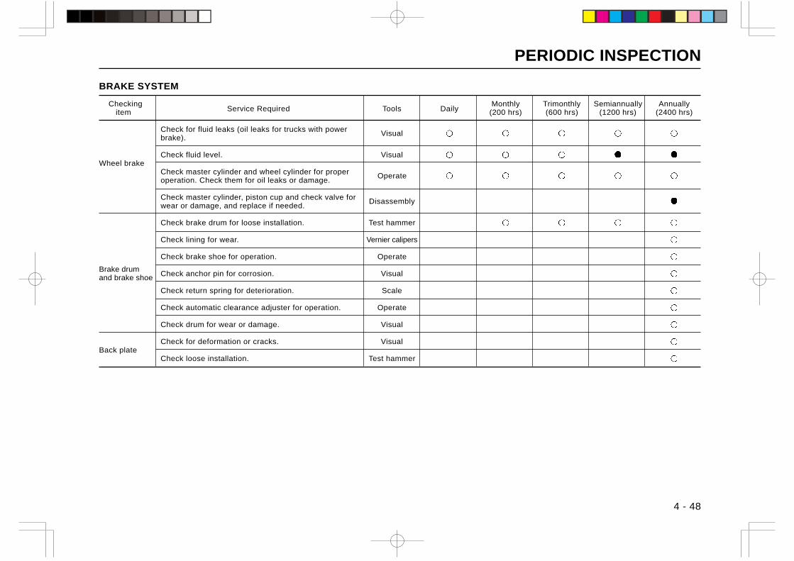
PERIODIC INSPECTION
4 - 48
BRAKE SYSTEM
Checking Service Required Tools Daily
Monthly Trimonthly Semiannually Annually item (200 hrs) (600 hrs) (1200 hrs) (2400 hrs)
Check for fluid leaks (oil leaks for trucks with power Visualbrake).
Check fluid level. VisualWheel brake
Check master cylinder and wheel cylinder for proper Operateoperation. Check them for oil leaks or damage.
Check master cylinder, piston cup and check valve for Disassemblywear or damage, and replace if needed.
Check brake drum for loose installation. Test hammer
Check lining for wear. Vernier calipers
Check brake shoe for operation. Operate
Brake drumand brake shoe Check anchor pin for corrosion. Visual
Check return spring for deterioration. Scale
Check automatic clearance adjuster for operation. Operate
Check drum for wear or damage. Visual
Check for deformation or cracks. VisualBack plate
Check loose installation. Test hammer
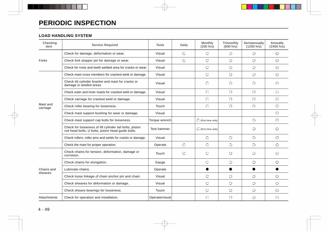
PERIODIC INSPECTION
4 - 49
LOAD HANDLING SYSTEM
Checking Service Required Tools Daily
Monthly Trimonthly Semiannually Annually item (200 hrs) (600 hrs) (1200 hrs) (2400 hrs)
Check for damage, deformation or wear. Visual
Forks Check fork stopper pin for damage or wear. Visual
Check for roots and teeth welded area for cracks or wear. Visual
Check mast cross members for cracked weld or damage. Visual
Check tilt cylinder bracket and mast for cracks or Visualdamage in welded areas.
Check outer and inner masts for cracked weld or damage. Visual
Check carriage for cracked weld or damage. Visual
Mast andcarriage Check roller bearing for looseness. Touch
Check mast support bushing for wear or damage. Visual
Check mast support cap bolts for looseness. Torque wrench (first time only)
Check for looseness of lift cylinder tail bolts, piston Test hammer (first time only)rod head bolts, U bolts, piston head guide bolts.
Check rollers, roller pins and welds for cracks or damage. Visual
Check the mast for proper operation. Operate
Check chains for tension, deformation, damage or Touchcorrosion.
Check chains for elongation. Gauge
Chains and Lubricate chains. Operatesheaves
Check loose linkage of chain anchor pin and chain. Visual
Check sheaves for deformation or damage. Visual
Check sheave bearings for looseness. Touch
Attachments Check for operation and installation. Operate/visual
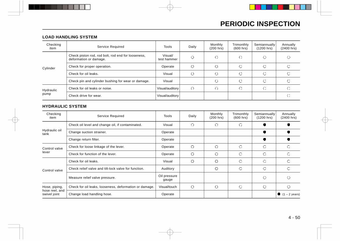
PERIODIC INSPECTION
4 - 50
LOAD HANDLING SYSTEM
Checking Service Required Tools Daily
Monthly Trimonthly Semiannually Annually item (200 hrs) (600 hrs) (1200 hrs) (2400 hrs)
Check piston rod, rod bolt, rod end for looseness, Visual/deformation or damage. test hammer
Cylinder Check for proper operation. Operate
Check for oil leaks. Visual
Check pin and cylinder bushing for wear or damage. Visual
Hydraulic Check for oil leaks or noise. Visual/auditory
pumpCheck drive for wear. Visual/auditory
HYDRAULIC SYSTEM
Checking Service Required Tools Daily
Monthly Trimonthly Semiannually Annually item (200 hrs) (600 hrs) (1200 hrs) (2400 hrs)
Check oil level and change oil, if contaminated. Visual
Hydraulic oiltank Change suction strainer. Operate
Change return filter. Operate
Control valve Check for loose linkage of the lever. Operate
leverCheck for function of the lever. Operate
Check for oil leaks. Visual
Control valve Check relief valve and tilt-lock valve for function. Auditory
Measure relief valve pressure. Oil pressuregauge
Hose, piping, Check for oil leaks, looseness, deformation or damage. Visual/touchhose reel, andswivel joint Change load handling hose. Operate (1 – 2 years)

PERIODIC INSPECTION
4 - 51
ELECTRICAL SYSTEM
Checking Service Required Tools Daily
Monthly Trimonthly Semiannually Annually item (200 hrs) (600 hrs) (1200 hrs) (2400 hrs)
Check distributor cap for cracks. Visual
Check spark plug for burn. Visual
Adjust spark plug gap. Plug gap gauge
Clean spark plug. Operate
Ignition device Check the insertion of high-voltage cable into distributor Visual(gas-powered cap.
trucks)Check distributor segment for burn. Visual
Check distributor center-piece for wear or damage. Visual
Check gap between signal rotor and stator. Thickness gauge
Lubricate distributor shaft. Operate
Check high-voltage cable for breakage. Tester
Starter Check proper engagement of pinion gears. Operate
Charger Check for proper operation. Ammeter
Check electrolyte level and clean. Visual/operateBattery
Check specific gravity of electrolyte. Gravimeter
Electrical Check wire harness for damage and loose clamp. Visual
wiringCheck for loose connections. Touch
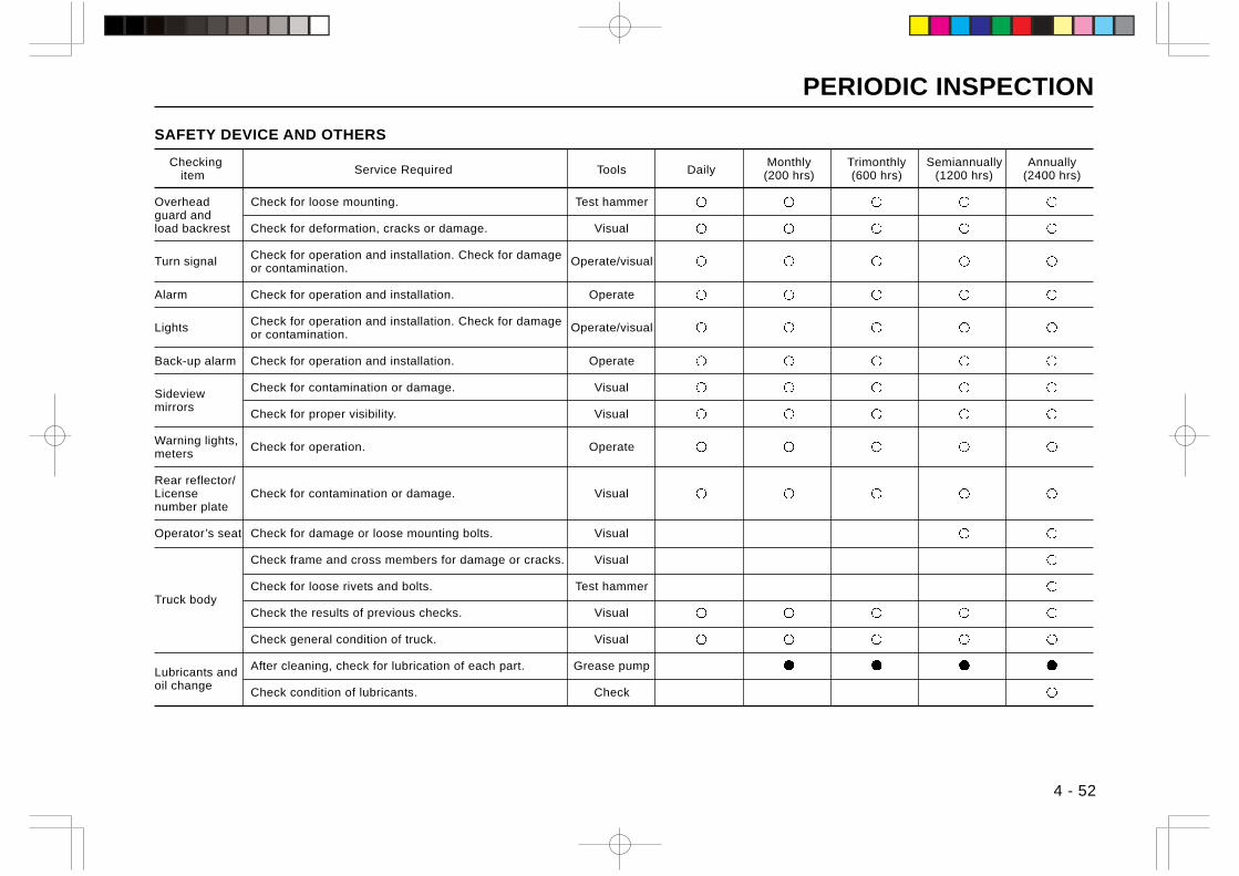
PERIODIC INSPECTION
SAFETY DEVICE AND OTHERS
Checking Service Required Tools Daily
Monthly Trimonthly Semiannually Annually item (200 hrs) (600 hrs) (1200 hrs) (2400 hrs)
Overhead Check for loose mounting. Test hammerguard andload backrest Check for deformation, cracks or damage. Visual
Turn signal Check for operation and installation. Check for damage Operate/visualor contamination.
Alarm Check for operation and installation. Operate
Lights Check for operation and installation. Check for damage Operate/visualor contamination.
Back-up alarm Check for operation and installation. Operate
Sideview Check for contamination or damage. Visual
mirrorsCheck for proper visibility. Visual
Warning lights, Check for operation. Operatemeters
Rear reflector/License Check for contamination or damage. Visualnumber plate
Operator’s seat Check for damage or loose mounting bolts. Visual
Check frame and cross members for damage or cracks. Visual
Check for loose rivets and bolts. Test hammerTruck body
Check the results of previous checks. Visual
Check general condition of truck. Visual
Lubricants and After cleaning, check for lubrication of each part. Grease pump
oil changeCheck condition of lubricants. Check
4 - 52

MEMO
dJ E ・E ・E ・.-=!I I I I ベト l - ・E ・E ・. I I ・・ |二
十 十
1-¥ ベト ¥-F
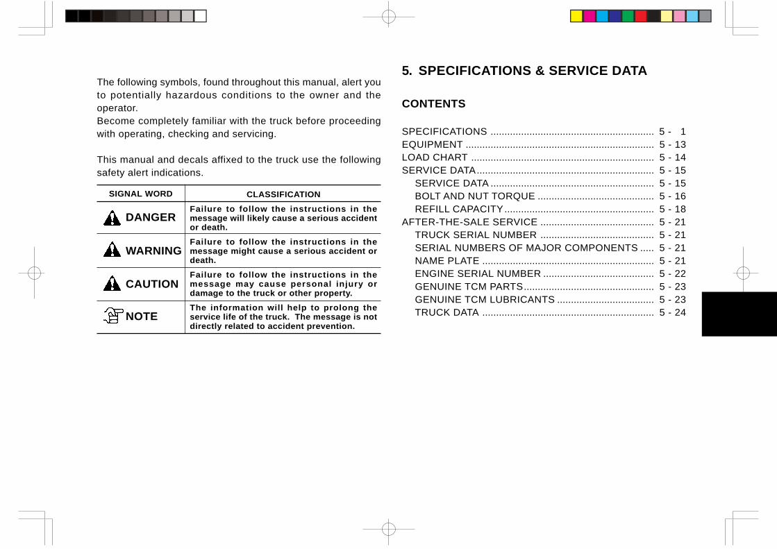
5. SPECIFICATIONS & SERVICE DATA
CONTENTS
SPECIFICATIONS ........................................................... 5 - 1EQUIPMENT .................................................................... 5 - 13LOAD CHART .................................................................. 5 - 14SERVICE DATA................................................................ 5 - 15
SERVICE DATA ........................................................... 5 - 15BOLT AND NUT TORQUE .......................................... 5 - 16REFILL CAPACITY...................................................... 5 - 18
AFTER-THE-SALE SERVICE ......................................... 5 - 21TRUCK SERIAL NUMBER ......................................... 5 - 21SERIAL NUMBERS OF MAJOR COMPONENTS ..... 5 - 21NAME PLATE .............................................................. 5 - 21ENGINE SERIAL NUMBER ........................................ 5 - 22GENUINE TCM PARTS............................................... 5 - 23GENUINE TCM LUBRICANTS ................................... 5 - 23TRUCK DATA .............................................................. 5 - 24
The following symbols, found throughout this manual, alert youto potentially hazardous conditions to the owner and theoperator.Become completely familiar with the truck before proceedingwith operating, checking and servicing.
This manual and decals affixed to the truck use the followingsafety alert indications.
SIGNAL WORD CLASSIFICATION
Failure to follow the instructions in themessage will likely cause a serious accidentor death.
Failure to follow the instructions in themessage might cause a serious accident ordeath.
Failure to follow the instructions in themessage may cause personal injury ordamage to the truck or other property.
The information will help to prolong theservice life of the truck. The message is notdirectly related to accident prevention.
DANGER
WARNING
CAUTION
NOTE
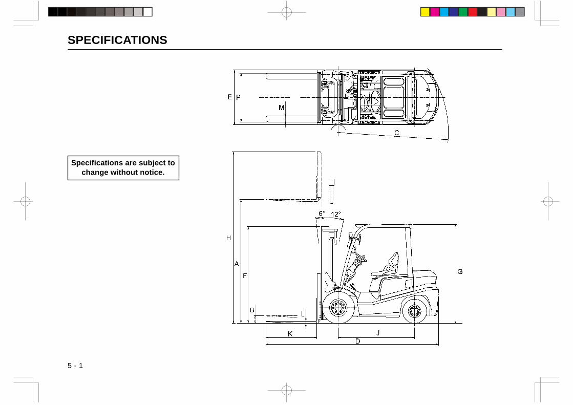
SPECIFICATIONS
5 - 1
Specifications are subject tochange without notice.
」
EIP
H
A
F
B
~
fh v
n
l|「1「
j ilH ----------二二二』 11
一------一一 L
K
fh y
60 12。
| ・・・・・・・・I I 圃 L
G
J
D
n==
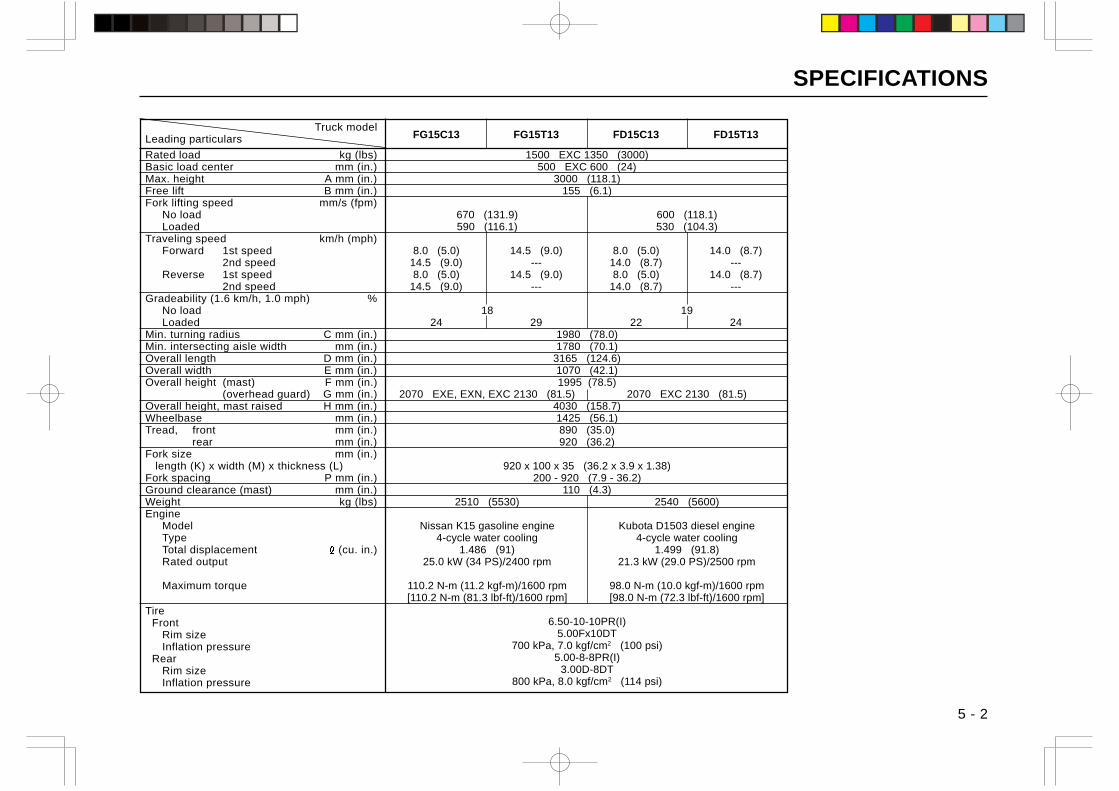
SPECIFICATIONS
5 - 2
Truck modelLeading particulars
Rated load kg (lbs)Basic load center mm (in.)Max. height A mm (in.)Free lift B mm (in.)Fork lifting speed mm/s (fpm)
No loadLoaded
Traveling speed km/h (mph)Forward 1st speed
2nd speedReverse 1st speed
2nd speedGradeability (1.6 km/h, 1.0 mph) %
No loadLoaded
Min. turning radius C mm (in.)Min. intersecting aisle width mm (in.)Overall length D mm (in.)Overall width E mm (in.)Overall height (mast) F mm (in.)
(overhead guard) G mm (in.)Overall height, mast raised H mm (in.)Wheelbase mm (in.)Tread, front mm (in.)
rear mm (in.)Fork size mm (in.) length (K) x width (M) x thickness (L)Fork spacing P mm (in.)Ground clearance (mast) mm (in.)Weight kg (lbs)Engine
ModelTypeTotal displacement (cu. in.)Rated output
Maximum torque
Tire Front
Rim sizeInflation pressure
RearRim sizeInflation pressure
FG15C13 FG15T13 FD15C13 FD15T13
1500 EXC 1350 (3000)500 EXC 600 (24)
3000 (118.1)155 (6.1)
670 (131.9) 600 (118.1)590 (116.1) 530 (104.3)
8.0 (5.0) 14.5 (9.0) 8.0 (5.0) 14.0 (8.7)14.5 (9.0) --- 14.0 (8.7) ---8.0 (5.0) 14.5 (9.0) 8.0 (5.0) 14.0 (8.7)
14.5 (9.0) --- 14.0 (8.7) ---
18 1924 29 22 24
1980 (78.0)1780 (70.1)
3165 (124.6)1070 (42.1)1995 (78.5)
2070 EXE, EXN, EXC 2130 (81.5) 2070 EXC 2130 (81.5)4030 (158.7)1425 (56.1)890 (35.0)920 (36.2)
920 x 100 x 35 (36.2 x 3.9 x 1.38)200 - 920 (7.9 - 36.2)
110 (4.3)2510 (5530) 2540 (5600)
Nissan K15 gasoline engine Kubota D1503 diesel engine4-cycle water cooling 4-cycle water cooling
1.486 (91) 1.499 (91.8)25.0 kW (34 PS)/2400 rpm 21.3 kW (29.0 PS)/2500 rpm
110.2 N-m (11.2 kgf-m)/1600 rpm 98.0 N-m (10.0 kgf-m)/1600 rpm[110.2 N-m (81.3 lbf-ft)/1600 rpm] [98.0 N-m (72.3 lbf-ft)/1600 rpm]
6.50-10-10PR(I)5.00Fx10DT
700 kPa, 7.0 kgf/cm2 (100 psi)5.00-8-8PR(I)
3.00D-8DT800 kPa, 8.0 kgf/cm2 (114 psi)
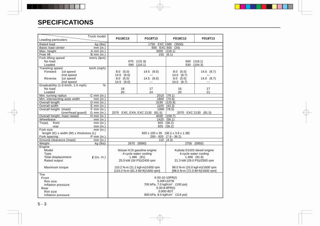
SPECIFICATIONS
5 - 3
Truck modelLeading particulars
Rated load kg (lbs)Basic load center mm (in.)Max. height A mm (in.)Free lift B mm (in.)Fork lifting speed mm/s (fpm)
No loadLoaded
Traveling speed km/h (mph)Forward 1st speed
2nd speedReverse 1st speed
2nd speedGradeability (1.6 km/h, 1.0 mph) %
No loadLoaded
Min. turning radius C mm (in.)Min. intersecting aisle width mm (in.)Overall length D mm (in.)Overall width E mm (in.)Overall height (mast) F mm (in.)
(overhead guard) G mm (in.)Overall height, mast raised H mm (in.)Wheelbase mm (in.)Tread, front mm (in.)
rear mm (in.)Fork size mm (in.) length (K) x width (M) x thickness (L)Fork spacing P mm (in.)Ground clearance (mast) mm (in.)Weight kg (lbs)Engine
ModelTypeTotal displacement (cu. in.)Rated output
Maximum torque
Tire Front
Rim sizeInflation pressure
RearRim sizeInflation pressure
FG18C13 FG18T13 FD18C13 FD18T13
1750 EXC 1580 (3500)500 EXC 600 (24)
3000 (118.1)155 (6.1)
670 (131.9) 600 (118.1)590 (116.1) 530 (104.3)
8.0 (5.0) 14.5 (9.0) 8.0 (5.0) 14.0 (8.7)14.5 (9.0) --- 14.0 (8.7) ---8.0 (5.0) 14.5 (9.0) 8.0 (5.0) 14.0 (8.7)
14.5 (9.0) --- 14.0 (8.7) ---
18 17 16 1720 24 20 21
2010 (79.1)1800 (70.9)
3195 (125.8)1100 (43.3)1995 (78.5)
2070 EXE, EXN, EXC 2130 (81.5) 2070 EXC 2130 (81.5)4030 (158.7)1425 (56.1)920 (36.2)920 (36.2)
920 x 100 x 35 (36.2 x 3.9 x 1.38)200 - 920 (7.9 - 36.2)
110 (4.3)2670 (5890) 2700 (5950)
Nissan K15 gasoline engine Kubota D1503 diesel engine4-cycle water cooling 4-cycle water cooling
1.486 (91) 1.499 (91.8)25.0 kW (34 PS)/2400 rpm 21.3 kW (29.0 PS)/2500 rpm
110.2 N-m (11.2 kgf-m)/1600 rpm 98.0 N-m (10.0 kgf-m)/1600 rpm[110.2 N-m (81.3 lbf-ft)/1600 rpm] [98.0 N-m (72.3 lbf-ft)/1600 rpm]
6.50-10-10PR(I)5.00Fx10TB
700 kPa, 7.0 kgf/cm2 (100 psi)5.00-8-8PR(I)
3.00D-8DT800 kPa, 8.0 kgf/cm2 (114 psi)

SPECIFICATIONS
5 - 4
Truck modelLeading particulars
Rated load kg (lbs)Basic load center mm (in.)Max. height A mm (in.)Free lift B mm (in.)Fork lifting speed mm/s (fpm)
No loadLoaded
Traveling speed km/h (mph)Forward 1st speed
2nd speedReverse 1st speed
2nd speedGradeability (1.6 km/h, 1.0 mph) %
No loadLoaded
Min. turning radius C mm (in.)Min. intersecting aisle width mm (in.)Overall length D mm (in.)Overall width E mm (in.)Overall height (mast) F mm (in.)
(overhead guard) G mm (in.)Overall height, mast raised H mm (in.)Wheelbase mm (in.)Tread, front mm (in.)
rear mm (in.)Fork size mm (in.) length (K) x width (M) x thickness (L)Fork spacing P mm (in.)Ground clearance (mast) mm (in.)Weight kg (lbs)Engine
ModelTypeTotal displacement (cu. in.)Rated output
Maximum torque
Tire Front
Rim sizeInflation pressure
RearRim sizeInflation pressure
FG20C3 FG20T3 FD20C3 FD20T3 FD20C3Z FD20T3Z
2000 EXC 1810 (4000)500 EXC 600 (24)
3000 (118.1)110 (4.3)
580 (114.2) 670 (131.9) 570 (112.2)540 (106.3) 630 (124.0) 530 (104.4)
8.5 (5.3) 19.0 (11.8) 8.5 (5.3) 18.5 (11.5) 8.0 (5.0) 18.5 (11.5)19.0 (11.8) --- 19.0 (11.8) --- 18.0 (11.2) ---8.5 (5.3) 19.0 (11.8) 8.5 (5.3) 18.5 (11.5) 8.0 (5.0) 18.5 (11.5)
19.0 (11.8) --- 19.0 (11.8) --- 18.0 (11.2) ---
20 20 2020 28 23 34 21 25
2170 (85.4)1950 (76.8)
3550 (139.8)1150 (45.3)2030 (79.9)
2070 EXE, EXN, EXC 2130 (81.5)4030 (158.7)1600 (63.0)970 (38.2)970 (38.2)
1070 x 122 x 40 (42.1 x 4.8 x 1.6)245 - 1020 (9.6 - 40.2)
110 (4.3)3210 (7080) 3340 (7360) 3320 (7320)
Nissan K21 gasoline engine Nissan Diesel TD27-II diesel engine Isuzu C240PKJ diesel engine4-cycle water cooling 4-cycle water cooling 4-cycle water cooling
2.065 (126.4) 2.663 (163) 2.369 (145)34.6 kW (48.6 PS)/2250 rpm 42.0 kW (57 PS)/2400 rpm 34.7 kW (47.2 PS)/2500 rpm
[41.0 kW (55 HP)/2300 rpm SAE GROSS] [46.5 HP/2500 rpm SAE GROSS]153.5 N-m (15.7 kgf-m)/1600 rpm 170 N-m (17.3 kgf-m)/2300 rpm 14.1 kgf-m/1800 rpm
[170 N-m (125 lbf-ft)/2300 rpm]
7.00-12-12PR(I)5.00S-12DT
700 kPa, 7.0 kgf/cm2 (100 psi)6.00-9-10PR(I)
4.00E-9DT700 kPa, 7.0 kgf/cm2 (100 psi)
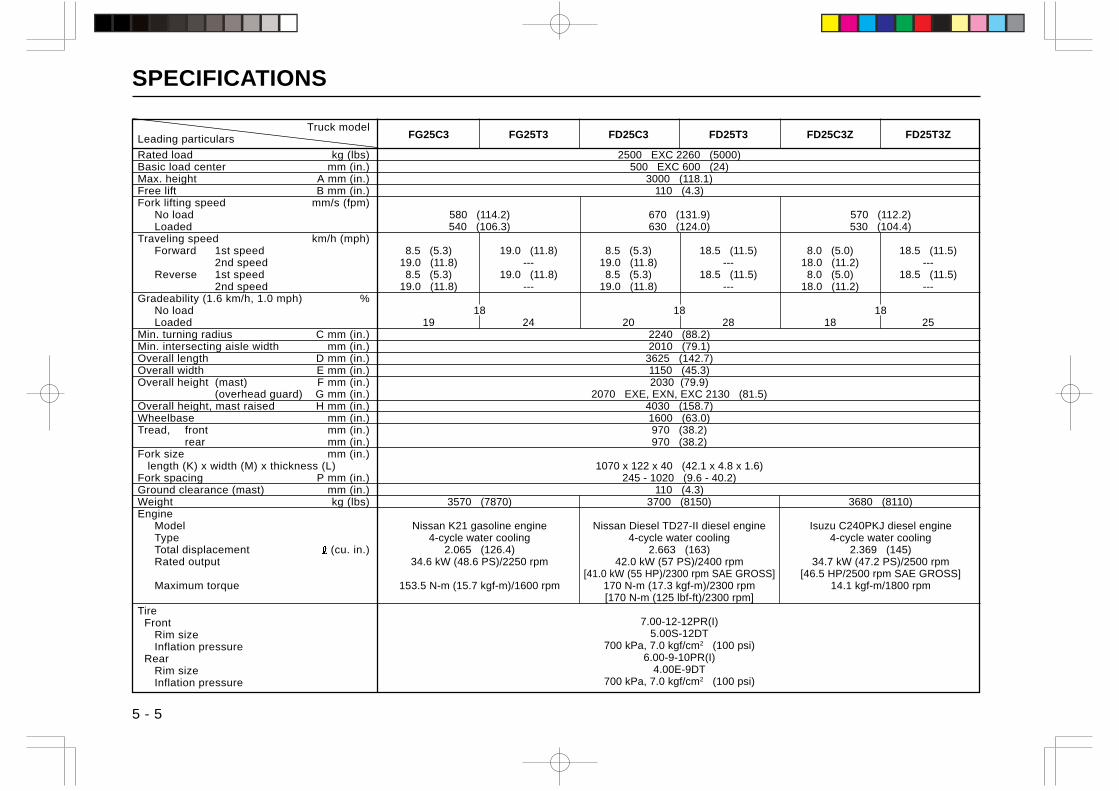
SPECIFICATIONS
5 - 5
Truck modelLeading particulars
Rated load kg (lbs)Basic load center mm (in.)Max. height A mm (in.)Free lift B mm (in.)Fork lifting speed mm/s (fpm)
No loadLoaded
Traveling speed km/h (mph)Forward 1st speed
2nd speedReverse 1st speed
2nd speedGradeability (1.6 km/h, 1.0 mph) %
No loadLoaded
Min. turning radius C mm (in.)Min. intersecting aisle width mm (in.)Overall length D mm (in.)Overall width E mm (in.)Overall height (mast) F mm (in.)
(overhead guard) G mm (in.)Overall height, mast raised H mm (in.)Wheelbase mm (in.)Tread, front mm (in.)
rear mm (in.)Fork size mm (in.) length (K) x width (M) x thickness (L)Fork spacing P mm (in.)Ground clearance (mast) mm (in.)Weight kg (lbs)Engine
ModelTypeTotal displacement (cu. in.)Rated output
Maximum torque
Tire Front
Rim sizeInflation pressure
RearRim sizeInflation pressure
FG25C3 FG25T3 FD25C3 FD25T3 FD25C3Z FD25T3Z
2500 EXC 2260 (5000)500 EXC 600 (24)
3000 (118.1)110 (4.3)
580 (114.2) 670 (131.9) 570 (112.2)540 (106.3) 630 (124.0) 530 (104.4)
8.5 (5.3) 19.0 (11.8) 8.5 (5.3) 18.5 (11.5) 8.0 (5.0) 18.5 (11.5)19.0 (11.8) --- 19.0 (11.8) --- 18.0 (11.2) ---8.5 (5.3) 19.0 (11.8) 8.5 (5.3) 18.5 (11.5) 8.0 (5.0) 18.5 (11.5)
19.0 (11.8) --- 19.0 (11.8) --- 18.0 (11.2) ---
18 18 1819 24 20 28 18 25
2240 (88.2)2010 (79.1)
3625 (142.7)1150 (45.3)2030 (79.9)
2070 EXE, EXN, EXC 2130 (81.5)4030 (158.7)1600 (63.0)970 (38.2)970 (38.2)
1070 x 122 x 40 (42.1 x 4.8 x 1.6)245 - 1020 (9.6 - 40.2)
110 (4.3)3570 (7870) 3700 (8150) 3680 (8110)
Nissan K21 gasoline engine Nissan Diesel TD27-II diesel engine Isuzu C240PKJ diesel engine4-cycle water cooling 4-cycle water cooling 4-cycle water cooling
2.065 (126.4) 2.663 (163) 2.369 (145)34.6 kW (48.6 PS)/2250 rpm 42.0 kW (57 PS)/2400 rpm 34.7 kW (47.2 PS)/2500 rpm
[41.0 kW (55 HP)/2300 rpm SAE GROSS] [46.5 HP/2500 rpm SAE GROSS]153.5 N-m (15.7 kgf-m)/1600 rpm 170 N-m (17.3 kgf-m)/2300 rpm 14.1 kgf-m/1800 rpm
[170 N-m (125 lbf-ft)/2300 rpm]
7.00-12-12PR(I)5.00S-12DT
700 kPa, 7.0 kgf/cm2 (100 psi)6.00-9-10PR(I)
4.00E-9DT700 kPa, 7.0 kgf/cm2 (100 psi)
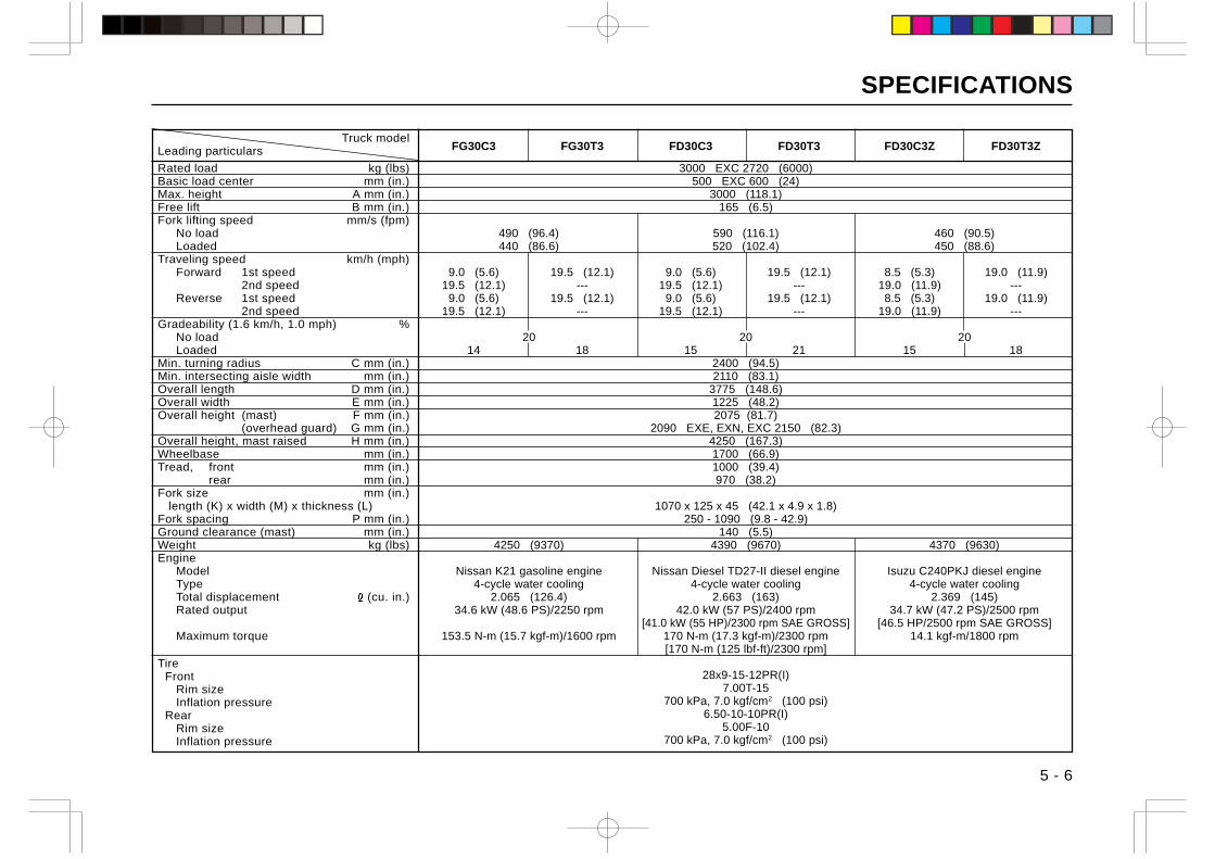
SPECIFICATIONS
5 - 6
Truck modelLeading particulars
Rated load kg (lbs)Basic load center mm (in.)Max. height A mm (in.)Free lift B mm (in.)Fork lifting speed mm/s (fpm)
No loadLoaded
Traveling speed km/h (mph)Forward 1st speed
2nd speedReverse 1st speed
2nd speedGradeability (1.6 km/h, 1.0 mph) %
No loadLoaded
Min. turning radius C mm (in.)Min. intersecting aisle width mm (in.)Overall length D mm (in.)Overall width E mm (in.)Overall height (mast) F mm (in.)
(overhead guard) G mm (in.)Overall height, mast raised H mm (in.)Wheelbase mm (in.)Tread, front mm (in.)
rear mm (in.)Fork size mm (in.) length (K) x width (M) x thickness (L)Fork spacing P mm (in.)Ground clearance (mast) mm (in.)Weight kg (lbs)Engine
ModelTypeTotal displacement (cu. in.)Rated output
Maximum torque
Tire Front
Rim sizeInflation pressure
RearRim sizeInflation pressure
FG30C3 FG30T3 FD30C3 FD30T3 FD30C3Z FD30T3Z
3000 EXC 2720 (6000)500 EXC 600 (24)
3000 (118.1)165 (6.5)
490 (96.4) 590 (116.1) 460 (90.5)440 (86.6) 520 (102.4) 450 (88.6)
9.0 (5.6) 19.5 (12.1) 9.0 (5.6) 19.5 (12.1) 8.5 (5.3) 19.0 (11.9)19.5 (12.1) --- 19.5 (12.1) --- 19.0 (11.9) ---
9.0 (5.6) 19.5 (12.1) 9.0 (5.6) 19.5 (12.1) 8.5 (5.3) 19.0 (11.9)19.5 (12.1) --- 19.5 (12.1) --- 19.0 (11.9) ---
20 20 2014 18 15 21 15 18
2400 (94.5)2110 (83.1)
3775 (148.6)1225 (48.2)2075 (81.7)
2090 EXE, EXN, EXC 2150 (82.3)4250 (167.3)1700 (66.9)1000 (39.4)970 (38.2)
1070 x 125 x 45 (42.1 x 4.9 x 1.8)250 - 1090 (9.8 - 42.9)
140 (5.5)4250 (9370) 4390 (9670) 4370 (9630)
Nissan K21 gasoline engine Nissan Diesel TD27-II diesel engine Isuzu C240PKJ diesel engine4-cycle water cooling 4-cycle water cooling 4-cycle water cooling
2.065 (126.4) 2.663 (163) 2.369 (145)34.6 kW (48.6 PS)/2250 rpm 42.0 kW (57 PS)/2400 rpm 34.7 kW (47.2 PS)/2500 rpm
[41.0 kW (55 HP)/2300 rpm SAE GROSS] [46.5 HP/2500 rpm SAE GROSS]153.5 N-m (15.7 kgf-m)/1600 rpm 170 N-m (17.3 kgf-m)/2300 rpm 14.1 kgf-m/1800 rpm
[170 N-m (125 lbf-ft)/2300 rpm]
28x9-15-12PR(I)7.00T-15
700 kPa, 7.0 kgf/cm2 (100 psi)6.50-10-10PR(I)
5.00F-10700 kPa, 7.0 kgf/cm2 (100 psi)
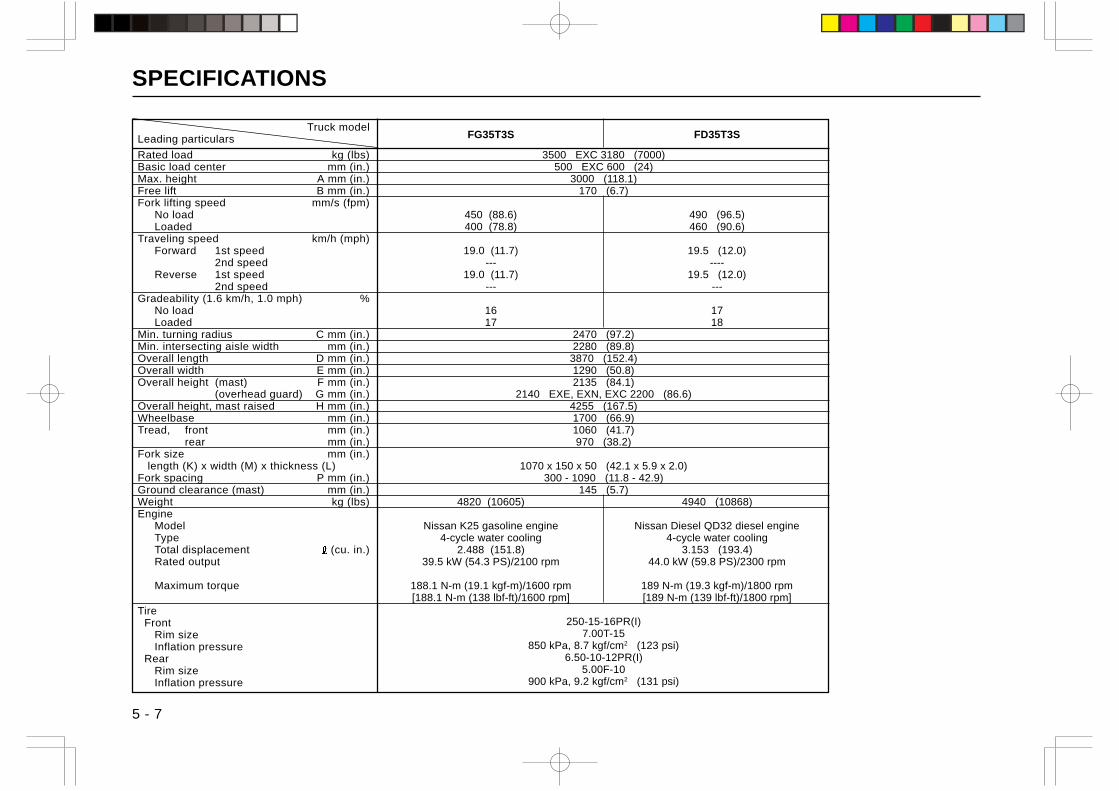
SPECIFICATIONS
5 - 7
Truck modelLeading particulars
Rated load kg (lbs)Basic load center mm (in.)Max. height A mm (in.)Free lift B mm (in.)Fork lifting speed mm/s (fpm)
No loadLoaded
Traveling speed km/h (mph)Forward 1st speed
2nd speedReverse 1st speed
2nd speedGradeability (1.6 km/h, 1.0 mph) %
No loadLoaded
Min. turning radius C mm (in.)Min. intersecting aisle width mm (in.)Overall length D mm (in.)Overall width E mm (in.)Overall height (mast) F mm (in.)
(overhead guard) G mm (in.)Overall height, mast raised H mm (in.)Wheelbase mm (in.)Tread, front mm (in.)
rear mm (in.)Fork size mm (in.) length (K) x width (M) x thickness (L)Fork spacing P mm (in.)Ground clearance (mast) mm (in.)Weight kg (lbs)Engine
ModelTypeTotal displacement (cu. in.)Rated output
Maximum torque
Tire Front
Rim sizeInflation pressure
RearRim sizeInflation pressure
FG35T3S FD35T3S
3500 EXC 3180 (7000)500 EXC 600 (24)
3000 (118.1)170 (6.7)
450 (88.6) 490 (96.5)400 (78.8) 460 (90.6)
19.0 (11.7) 19.5 (12.0)--- ----
19.0 (11.7) 19.5 (12.0)--- ---
16 1717 18
2470 (97.2)2280 (89.8)
3870 (152.4)1290 (50.8)2135 (84.1)
2140 EXE, EXN, EXC 2200 (86.6)4255 (167.5)1700 (66.9)1060 (41.7)970 (38.2)
1070 x 150 x 50 (42.1 x 5.9 x 2.0)300 - 1090 (11.8 - 42.9)
145 (5.7)4820 (10605) 4940 (10868)
Nissan K25 gasoline engine Nissan Diesel QD32 diesel engine4-cycle water cooling 4-cycle water cooling
2.488 (151.8) 3.153 (193.4)39.5 kW (54.3 PS)/2100 rpm 44.0 kW (59.8 PS)/2300 rpm
188.1 N-m (19.1 kgf-m)/1600 rpm 189 N-m (19.3 kgf-m)/1800 rpm[188.1 N-m (138 lbf-ft)/1600 rpm] [189 N-m (139 lbf-ft)/1800 rpm]
250-15-16PR(I)7.00T-15
850 kPa, 8.7 kgf/cm2 (123 psi)6.50-10-12PR(I)
5.00F-10900 kPa, 9.2 kgf/cm2 (131 psi)
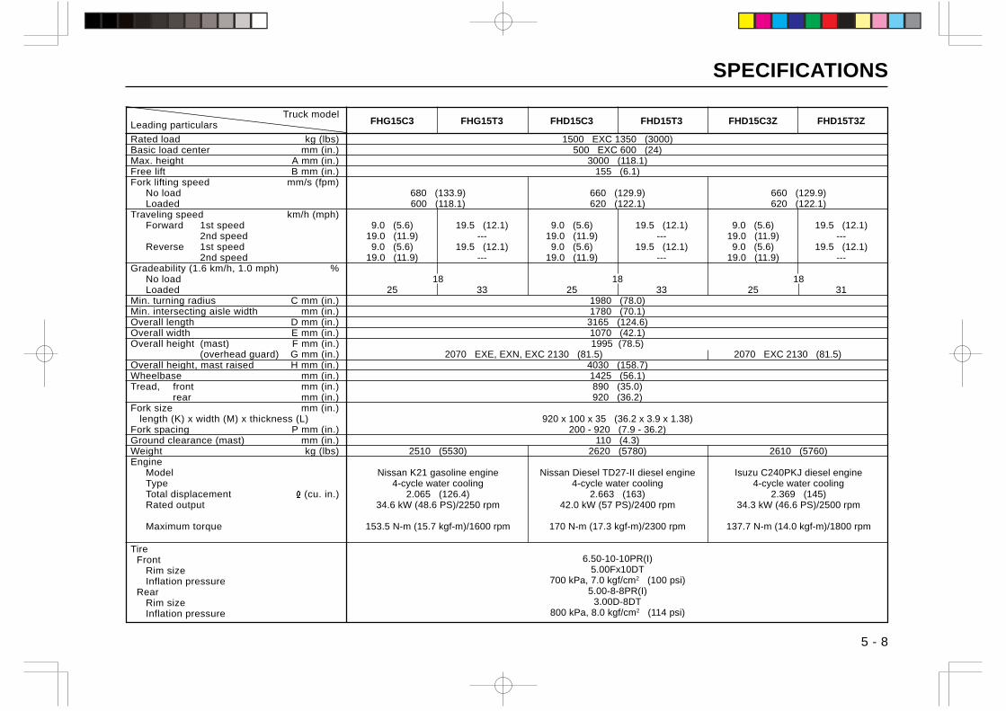
SPECIFICATIONS
5 - 8
Truck modelLeading particulars
Rated load kg (lbs)Basic load center mm (in.)Max. height A mm (in.)Free lift B mm (in.)Fork lifting speed mm/s (fpm)
No loadLoaded
Traveling speed km/h (mph)Forward 1st speed
2nd speedReverse 1st speed
2nd speedGradeability (1.6 km/h, 1.0 mph) %
No loadLoaded
Min. turning radius C mm (in.)Min. intersecting aisle width mm (in.)Overall length D mm (in.)Overall width E mm (in.)Overall height (mast) F mm (in.)
(overhead guard) G mm (in.)Overall height, mast raised H mm (in.)Wheelbase mm (in.)Tread, front mm (in.)
rear mm (in.)Fork size mm (in.) length (K) x width (M) x thickness (L)Fork spacing P mm (in.)Ground clearance (mast) mm (in.)Weight kg (lbs)Engine
ModelTypeTotal displacement (cu. in.)Rated output
Maximum torque
Tire Front
Rim sizeInflation pressure
RearRim sizeInflation pressure
FHG15C3 FHG15T3 FHD15C3 FHD15T3 FHD15C3Z FHD15T3Z
1500 EXC 1350 (3000)500 EXC 600 (24)
3000 (118.1)155 (6.1)
680 (133.9) 660 (129.9) 660 (129.9)600 (118.1) 620 (122.1) 620 (122.1)
9.0 (5.6) 19.5 (12.1) 9.0 (5.6) 19.5 (12.1) 9.0 (5.6) 19.5 (12.1)19.0 (11.9) --- 19.0 (11.9) --- 19.0 (11.9) ---9.0 (5.6) 19.5 (12.1) 9.0 (5.6) 19.5 (12.1) 9.0 (5.6) 19.5 (12.1)
19.0 (11.9) --- 19.0 (11.9) --- 19.0 (11.9) ---
18 18 1825 33 25 33 25 31
1980 (78.0)1780 (70.1)
3165 (124.6)1070 (42.1)1995 (78.5)
2070 EXE, EXN, EXC 2130 (81.5) 2070 EXC 2130 (81.5)4030 (158.7)1425 (56.1)890 (35.0)920 (36.2)
920 x 100 x 35 (36.2 x 3.9 x 1.38)200 - 920 (7.9 - 36.2)
110 (4.3)2510 (5530) 2620 (5780) 2610 (5760)
Nissan K21 gasoline engine Nissan Diesel TD27-II diesel engine Isuzu C240PKJ diesel engine4-cycle water cooling 4-cycle water cooling 4-cycle water cooling
2.065 (126.4) 2.663 (163) 2.369 (145)34.6 kW (48.6 PS)/2250 rpm 42.0 kW (57 PS)/2400 rpm 34.3 kW (46.6 PS)/2500 rpm
153.5 N-m (15.7 kgf-m)/1600 rpm 170 N-m (17.3 kgf-m)/2300 rpm 137.7 N-m (14.0 kgf-m)/1800 rpm
6.50-10-10PR(I)5.00Fx10DT
700 kPa, 7.0 kgf/cm2 (100 psi)5.00-8-8PR(I)
3.00D-8DT800 kPa, 8.0 kgf/cm2 (114 psi)
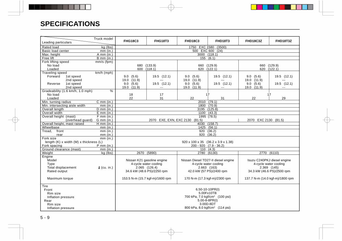
SPECIFICATIONS
5 - 9
Truck modelLeading particulars
Rated load kg (lbs)Basic load center mm (in.)Max. height A mm (in.)Free lift B mm (in.)Fork lifting speed mm/s (fpm)
No loadLoaded
Traveling speed km/h (mph)Forward 1st speed
2nd speedReverse 1st speed
2nd speedGradeability (1.6 km/h, 1.0 mph) %
No loadLoaded
Min. turning radius C mm (in.)Min. intersecting aisle width mm (in.)Overall length D mm (in.)Overall width E mm (in.)Overall height (mast) F mm (in.)
(overhead guard) G mm (in.)Overall height, mast raised H mm (in.)Wheelbase mm (in.)Tread, front mm (in.)
rear mm (in.)Fork size mm (in.) length (K) x width (M) x thickness (L)Fork spacing P mm (in.)Ground clearance (mast) mm (in.)Weight kg (lbs)Engine
ModelTypeTotal displacement (cu. in.)Rated output
Maximum torque
Tire Front
Rim sizeInflation pressure
RearRim sizeInflation pressure
FHG18C3 FHG18T3 FHD18C3 FHD18T3 FHD18C3Z FHD18T3Z
1750 EXC 1580 (3500)500 EXC 600 (24)
3000 (118.1)155 (6.1)
680 (133.9) 660 (129.9) 660 (129.9)600 (118.1) 620 (122.1) 620 (122.1)
9.0 (5.6) 19.5 (12.1) 9.0 (5.6) 19.5 (12.1) 9.0 (5.6) 19.5 (12.1)19.0 (11.9) --- 19.0 (11.9) --- 19.0 (11.9) ---9.0 (5.6) 19.5 (12.1) 9.0 (5.6) 19.5 (12.1) 9.0 (5.6) 19.5 (12.1)
19.0 (11.9) --- 19.0 (11.9) --- 19.0 (11.9) ---
18 17 17 1722 31 22 31 22 29
2010 (79.1)1800 (70.9)
3195 (125.8)1100 (43.3)1995 (78.5)
2070 EXE, EXN, EXC 2130 (81.5) 2070 EXC 2130 (81.5)4030 (158.7)1425 (56.1)920 (36.2)920 (36.2)
920 x 100 x 35 (36.2 x 3.9 x 1.38)200 - 920 (7.9 - 36.2)
110 (4.3)2670 (5890) 2780 (6130) 2770 (6110)
Nissan K21 gasoline engine Nissan Diesel TD27-II diesel engine Isuzu C240PKJ diesel engine4-cycle water cooling 4-cycle water cooling 4-cycle water cooling
2.065 (126.4) 2.663 (163) 2.369 (145)34.6 kW (48.6 PS)/2250 rpm 42.0 kW (57 PS)/2400 rpm 34.3 kW (46.6 PS)/2500 rpm
153.5 N-m (15.7 kgf-m)/1600 rpm 170 N-m (17.3 kgf-m)/2300 rpm 137.7 N-m (14.0 kgf-m)/1800 rpm
6.50-10-10PR(I)5.00Fx10TB
700 kPa, 7.0 kgf/cm2 (100 psi)5.00-8-8PR(I)
3.00D-8DT800 kPa, 8.0 kgf/cm2 (114 psi)

SPECIFICATIONS
Truck modelLeading particulars
Rated load kg (lbs)Basic load center mm (in.)Max. height A mm (in.)Free lift B mm (in.)Fork lifting speed mm/s (fpm)
No loadLoaded
Traveling speed km/h (mph)Forward 1st speed
2nd speedReverse 1st speed
2nd speedGradeability (1.6 km/h, 1.0 mph) %
No loadLoaded
Min. turning radius C mm (in.)Min. intersecting aisle width mm (in.)Overall length D mm (in.)Overall width E mm (in.)Overall height (mast) F mm (in.)
(overhead guard) G mm (in.)Overall height, mast raised H mm (in.)Wheelbase mm (in.)Tread, front mm (in.)
rear mm (in.)Fork size mm (in.) length (K) x width (M) x thickness (L)Fork spacing P mm (in.)Ground clearance (mast) mm (in.)Weight kg (lbs)Engine
ModelTypeTotal displacement (cu. in.)Rated output
Maximum torque
Tire Front
Rim sizeInflation pressure
RearRim sizeInflation pressure
FHG20C3 FHG20T3 FHD20C3 FHD20T3 FHD20C3A FHD20T3A
2000 EXC 1810 (4000)500 EXC 600 (24)
3000 (118.1)110 (4.3)
620 (122.1) 640 (126.0) 670 (131.9)600 (118.1) 620 (122.0) 630 (124.0)
9.0 (5.6) 19.0 (11.8) 9.0 (5.6) 18.5 (11.5) 8.5 (5.3) 18.5 (11.5)19.0 (11.8) --- 18.5 (11.5) --- 19.0 (11.8) ---9.0 (5.6) 19.0 (11.8) 9.0 (5.6) 18.5 (11.5) 8.5 (5.3) 18.5 (11.5)
19.0 (11.8) --- 18.5 (11.5) --- 19.0 (11.8) ---
20 20 2024 36 28 38 26 36
2170 (85.4)1950 (76.8)
3550 (139.8)1150 (45.3)2030 (79.9)
2070 EXE, EXN, EXC 2130 (81.5)4030 (158.7)1600 (63.0)970 (38.2)970 (38.2)
1070 x 122 x 40 (42.1 x 4.8 x 1.6)245 - 1020 (9.6 - 40.2)
110 (4.3)3220 (7110) 3340 (7360) 3340 (7360)
Nissan K25 gasoline engine Kubota V3300 diesel engine Nissan Diesel QD32 diesel engine4-cycle water cooling 4-cycle water cooling 4-cycle water cooling
2.488 (151.8) 3.318 (203.1) 3.153 (193.4)39.5 kW (54.3 PS)/2100 rpm 50 kW (67 PS)/2500 rpm 44.0 kW (59.8 PS)/2300 rpm
[46.3 kW (62 HP)/2300 rpm SAE GROSS]188.1 N-m (19.1 kgf-m)/1600 rpm 226.4 N-m (23.1 kgf-m)/1800 rpm 189 N-m {19.3 kgf-m)/1800 rpm
[226.4 N-m (167.1 lbf-ft)/1800 rpm] [189 N-m (139 lbf-ft)/1800 rpm]
7.00-12-12PR(I)5.00S-12DT
700 kPa, 7.0 kgf/cm2 (100 psi)6.00-9-10PR(I)
4.00E-9DT700 kPa, 7.0 kgf/cm2 (100 psi)
5 - 10
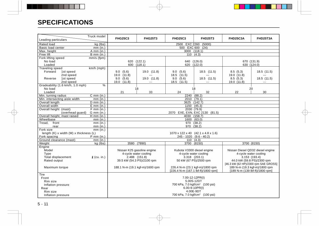
SPECIFICATIONS
Truck modelLeading particulars
Rated load kg (lbs)Basic load center mm (in.)Max. height A mm (in.)Free lift B mm (in.)Fork lifting speed mm/s (fpm)
No loadLoaded
Traveling speed km/h (mph)Forward 1st speed
2nd speedReverse 1st speed
2nd speedGradeability (1.6 km/h, 1.0 mph) %
No loadLoaded
Min. turning radius C mm (in.)Min. intersecting aisle width mm (in.)Overall length D mm (in.)Overall width E mm (in.)Overall height (mast) F mm (in.)
(overhead guard) G mm (in.)Overall height, mast raised H mm (in.)Wheelbase mm (in.)Tread, front mm (in.)
rear mm (in.)Fork size mm (in.) length (K) x width (M) x thickness (L)Fork spacing P mm (in.)Ground clearance (mast) mm (in.)Weight kg (lbs)Engine
ModelTypeTotal displacement (cu. in.)Rated output
Maximum torque
Tire Front
Rim sizeInflation pressure
RearRim sizeInflation pressure
FHG25C3 FHG25T3 FHD25C3 FHD25T3 FHD25C3A FHD25T3A
2500 EXC 2260 (5000)500 EXC 600 (24)
3000 (118.1)110 (4.3)
620 (122.1) 640 (126.0) 670 (131.9)600 (118.1) 620 (122.0) 630 (124.0)
9.0 (5.6) 19.0 (11.8) 9.0 (5.6) 18.5 (11.5) 8.5 (5.3) 18.5 (11.5)19.0 (11.8) --- 18.5 (11.5) --- 19.0 (11.8) ---9.0 (5.6) 19.0 (11.8) 9.0 (5.6) 18.5 (11.5) 8.5 (5.3) 18.5 (11.5)
19.0 (11.8) --- 18.5 (11.5) --- 19.0 (11.8) ---
18 18 2021 33 24 32 22 30
2240 (88.2)2010 (79.1)
3625 (142.7)1150 (45.3)2030 (79.9)
2070 EXE, EXN, EXC 2130 (81.5)4030 (158.7)1600 (63.0)970 (38.2)970 (38.2)
1070 x 122 x 40 (42.1 x 4.8 x 1.6)245 - 1020 (9.6 - 40.2)
110 (4.3)3580 (7890) 3700 (8150) 3700 (8150)
Nissan K25 gasoline engine Kubota V3300 diesel engine Nissan Diesel QD32 diesel engine4-cycle water cooling 4-cycle water cooling 4-cycle water cooling
2.488 (151.8) 3.318 (203.1) 3.153 (193.4)39.5 kW (54.3 PS)/2100 rpm 50 kW (67 PS)/2500 rpm 44.0 kW (59.8 PS)/2300 rpm
[46.3 kW (62 HP)/2300 rpm SAE GROSS]188.1 N-m (19.1 kgf-m)/1600 rpm 226.4 N-m (23.1 kgf-m)/1800 rpm 189 N-m (19.3 kgf-m)/1800 rpm
[226.4 N-m (167.1 lbf-ft)/1800 rpm] [189 N-m (139 lbf-ft)/1800 rpm]
7.00-12-12PR(I)5.00S-12DT
700 kPa, 7.0 kgf/cm2 (100 psi)6.00-9-10PR(I)
4.00E-9DT700 kPa, 7.0 kgf/cm2 (100 psi)
5 - 11
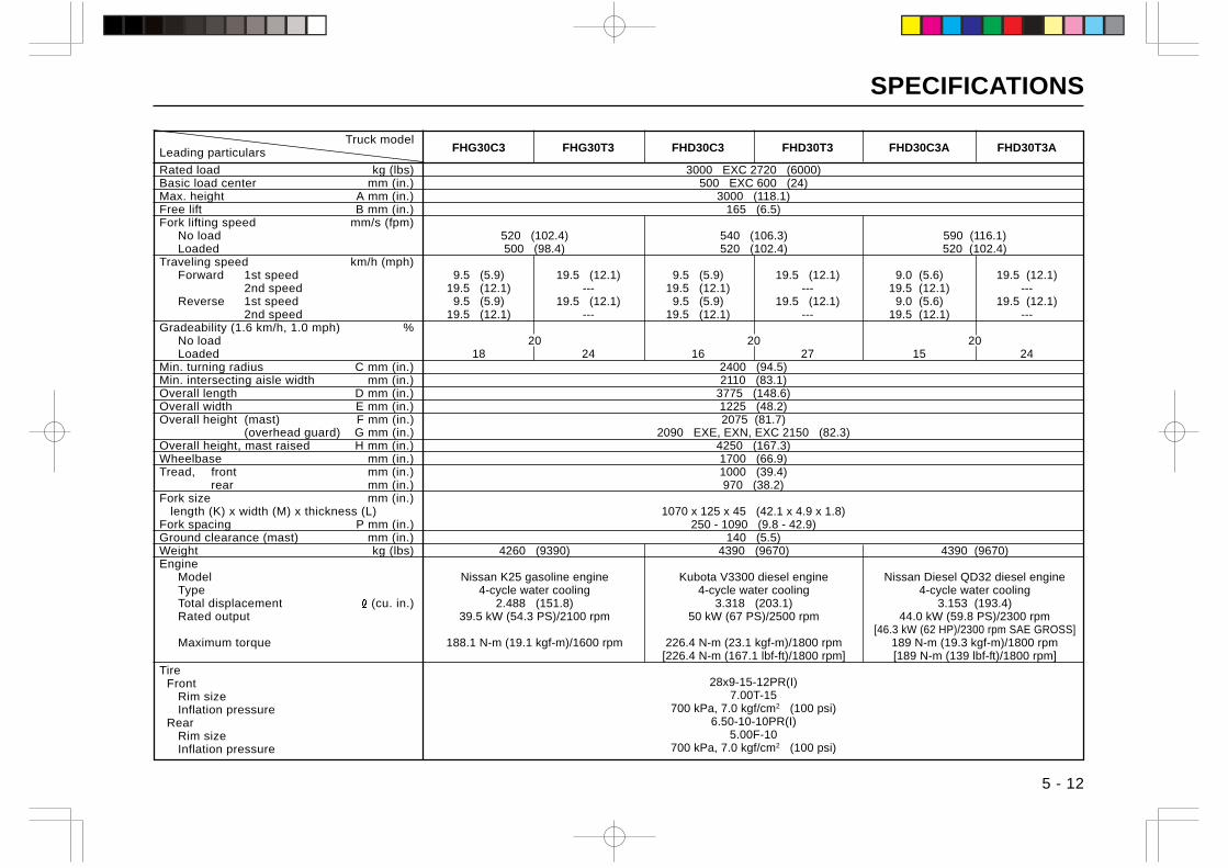
SPECIFICATIONS
Truck modelLeading particulars
Rated load kg (lbs)Basic load center mm (in.)Max. height A mm (in.)Free lift B mm (in.)Fork lifting speed mm/s (fpm)
No loadLoaded
Traveling speed km/h (mph)Forward 1st speed
2nd speedReverse 1st speed
2nd speedGradeability (1.6 km/h, 1.0 mph) %
No loadLoaded
Min. turning radius C mm (in.)Min. intersecting aisle width mm (in.)Overall length D mm (in.)Overall width E mm (in.)Overall height (mast) F mm (in.)
(overhead guard) G mm (in.)Overall height, mast raised H mm (in.)Wheelbase mm (in.)Tread, front mm (in.)
rear mm (in.)Fork size mm (in.) length (K) x width (M) x thickness (L)Fork spacing P mm (in.)Ground clearance (mast) mm (in.)Weight kg (lbs)Engine
ModelTypeTotal displacement (cu. in.)Rated output
Maximum torque
Tire Front
Rim sizeInflation pressure
RearRim sizeInflation pressure
FHG30C3 FHG30T3 FHD30C3 FHD30T3 FHD30C3A FHD30T3A
3000 EXC 2720 (6000)500 EXC 600 (24)
3000 (118.1)165 (6.5)
520 (102.4) 540 (106.3) 590 (116.1)500 (98.4) 520 (102.4) 520 (102.4)
9.5 (5.9) 19.5 (12.1) 9.5 (5.9) 19.5 (12.1) 9.0 (5.6) 19.5 (12.1)19.5 (12.1) --- 19.5 (12.1) --- 19.5 (12.1) ---
9.5 (5.9) 19.5 (12.1) 9.5 (5.9) 19.5 (12.1) 9.0 (5.6) 19.5 (12.1)19.5 (12.1) --- 19.5 (12.1) --- 19.5 (12.1) ---
20 20 2018 24 16 27 15 24
2400 (94.5)2110 (83.1)
3775 (148.6)1225 (48.2)2075 (81.7)
2090 EXE, EXN, EXC 2150 (82.3)4250 (167.3)1700 (66.9)1000 (39.4)970 (38.2)
1070 x 125 x 45 (42.1 x 4.9 x 1.8)250 - 1090 (9.8 - 42.9)
140 (5.5)4260 (9390) 4390 (9670) 4390 (9670)
Nissan K25 gasoline engine Kubota V3300 diesel engine Nissan Diesel QD32 diesel engine4-cycle water cooling 4-cycle water cooling 4-cycle water cooling
2.488 (151.8) 3.318 (203.1) 3.153 (193.4)39.5 kW (54.3 PS)/2100 rpm 50 kW (67 PS)/2500 rpm 44.0 kW (59.8 PS)/2300 rpm
[46.3 kW (62 HP)/2300 rpm SAE GROSS]188.1 N-m (19.1 kgf-m)/1600 rpm 226.4 N-m (23.1 kgf-m)/1800 rpm 189 N-m (19.3 kgf-m)/1800 rpm
[226.4 N-m (167.1 lbf-ft)/1800 rpm] [189 N-m (139 lbf-ft)/1800 rpm]
28x9-15-12PR(I)7.00T-15
700 kPa, 7.0 kgf/cm2 (100 psi)6.50-10-10PR(I)
5.00F-10700 kPa, 7.0 kgf/cm2 (100 psi)
5 - 12
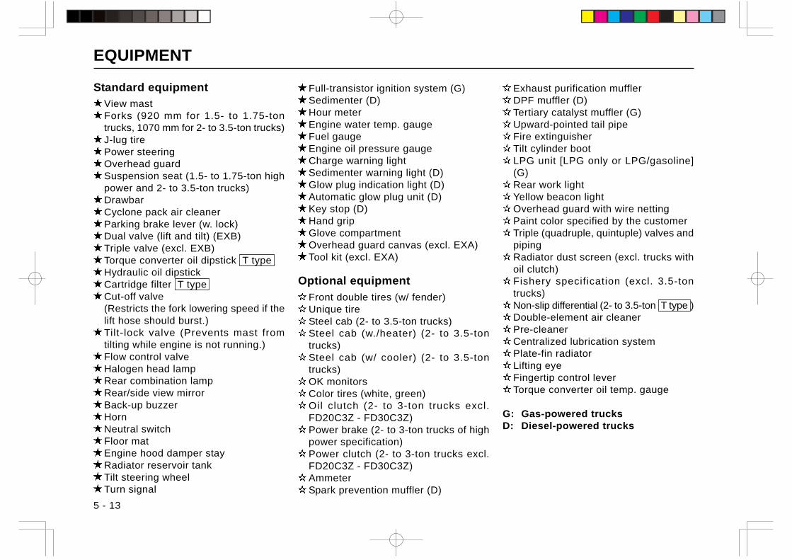
EQUIPMENT
5 - 13
Standard equipment
View mastForks (920 mm for 1.5- to 1.75-tontrucks, 1070 mm for 2- to 3.5-ton trucks)J-lug tirePower steeringOverhead guardSuspension seat (1.5- to 1.75-ton highpower and 2- to 3.5-ton trucks)DrawbarCyclone pack air cleanerParking brake lever (w. lock)Dual valve (lift and tilt) (EXB)Triple valve (excl. EXB)Torque converter oil dipstick T typeHydraulic oil dipstickCartridge filter T typeCut-off valve(Restricts the fork lowering speed if thelift hose should burst.)Tilt-lock valve (Prevents mast fromtilting while engine is not running.)Flow control valveHalogen head lampRear combination lampRear/side view mirrorBack-up buzzerHornNeutral switchFloor matEngine hood damper stayRadiator reservoir tankTilt steering wheelTurn signal
Full-transistor ignition system (G)Sedimenter (D)Hour meterEngine water temp. gaugeFuel gaugeEngine oil pressure gaugeCharge warning lightSedimenter warning light (D)Glow plug indication light (D)Automatic glow plug unit (D)Key stop (D)Hand gripGlove compartmentOverhead guard canvas (excl. EXA)Tool kit (excl. EXA)
Optional equipment
Front double tires (w/ fender)Unique tireSteel cab (2- to 3.5-ton trucks)Steel cab (w./heater) (2- to 3.5-tontrucks)Steel cab (w/ cooler) (2- to 3.5-tontrucks)OK monitorsColor tires (white, green)Oil clutch (2- to 3-ton trucks excl.FD20C3Z - FD30C3Z)Power brake (2- to 3-ton trucks of highpower specification)Power clutch (2- to 3-ton trucks excl.FD20C3Z - FD30C3Z)AmmeterSpark prevention muffler (D)
Exhaust purification mufflerDPF muffler (D)Tertiary catalyst muffler (G)Upward-pointed tail pipeFire extinguisherTilt cylinder bootLPG unit [LPG only or LPG/gasoline](G)Rear work lightYellow beacon lightOverhead guard with wire nettingPaint color specified by the customerTriple (quadruple, quintuple) valves andpipingRadiator dust screen (excl. trucks withoil clutch)Fishery specification (excl. 3.5-tontrucks)Non-slip differential (2- to 3.5-ton T type )Double-element air cleanerPre-cleanerCentralized lubrication systemPlate-fin radiatorLifting eyeFingertip control leverTorque converter oil temp. gauge
G: Gas-powered trucksD: Diesel-powered trucks
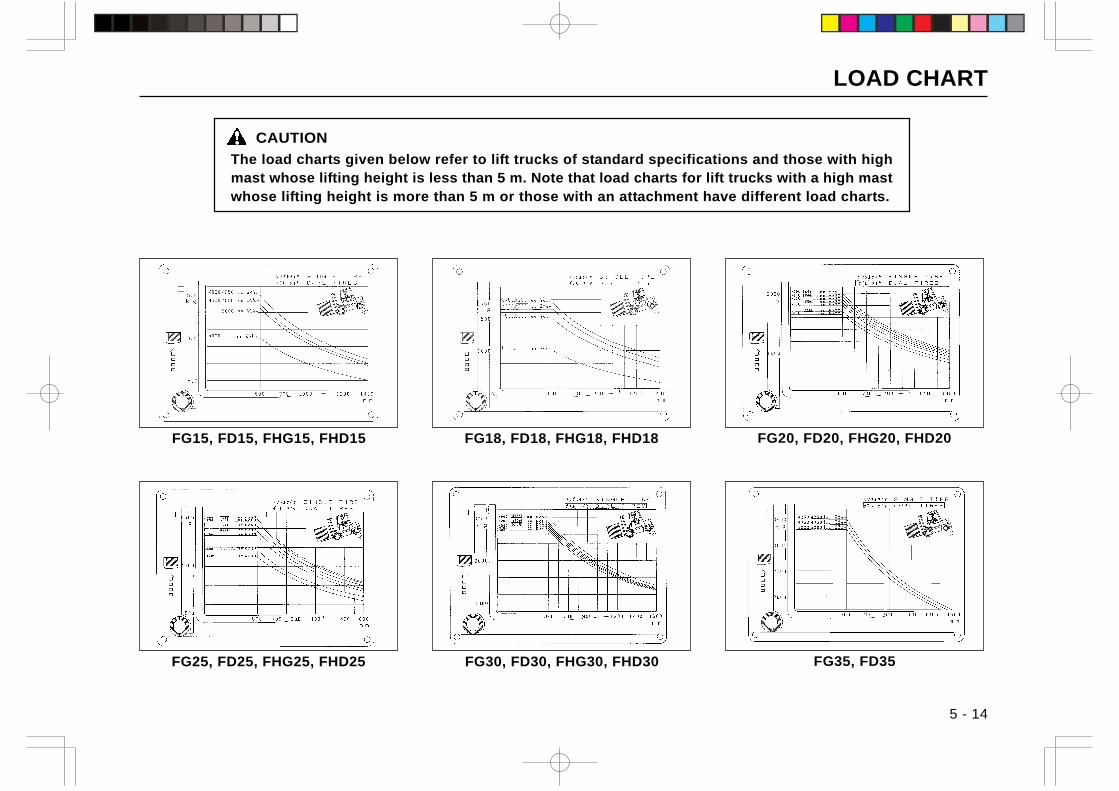
LOAD CHART
5 - 14
FG20, FD20, FHG20, FHD20
FG30, FD30, FHG30, FHD30FG25, FD25, FHG25, FHD25
CAUTION
The load charts given below refer to lift trucks of standard specifications and those with highmast whose lifting height is less than 5 m. Note that load charts for lift trucks with a high mastwhose lifting height is more than 5 m or those with an attachment have different load charts.
FG18, FD18, FHG18, FHD18FG15, FD15, FHG15, FHD15
FG35, FD35
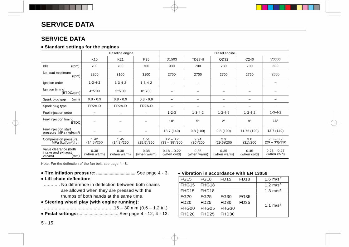
SERVICE DATA
5 - 15
••••• Tire inflation pressure: ................................ See page 4 - 3.••••• Lift chain deflection: ............ No difference in deflection between both chains
are allowed when they are pressed with thethumbs of both hands at the same time.
••••• Steering wheel play (with engine running): ....................................................15 – 30 mm (0.6 – 1.2 in.)••••• Pedal settings: ................................ See page 4 - 12, 4 - 13.
Idle (rpm)
No-load maximum(rpm)
Ignition order
Ignition timing(BTDC/rpm)
Spark plug gap (mm)
Spark plug type
Fuel injection order
Fuel injection timingBTDC
Fuel injection startpressure MPa (kgf/cm2)
Compression pressureMPa (kgf/cm2)/rpm
Valve clearance (bothintake and exhaustvalves) (mm)
Note: For the deflection of the fan belt, see page 4 - 8.
Gasoline engine Diesel engine
K21
700
3100
1-3-4-2
2°/700
0.8 - 0.9
FR2A-D
–
–
–
1.45(14.8)/250
0.38(when warm)
K25
700
3100
1-3-4-2
0°/700
0.8 - 0.9
FR2A-D
–
–
–
1.51(15.5)/250
0.38(when warm)
TD27-II
700
2700
–
–
–
–
1-3-4-2
5°
9.8 (100)
2.94(30)/200
0.35(when warm)
QD32
730
2700
–
–
–
–
1-3-4-2
2°
9.8 (100)
2.9(29.6)/200
0.35(when warm)
C240
700
2750
–
–
–
–
1-3-4-2
9°
11.76 (120)
3.0(31)/200
0.45(when cold)
SERVICE DATA••••• Standard settings for the engines
D1503
930
2700
–
–
–
–
1-2-3
18°
13.7 (140)
3.2 – 3.7(33 – 38)/300
0.18 – 0.22(when cold)
K15
700
3200
1-3-4-2
4°/700
0.8 - 0.9
FR2A-D
–
–
–
1.42(14.5)/250
0.38(when warm)
V3300
800
2650
–
–
–
–
1-3-4-2
16°
13.7 (140)
2.8 – 3.2(29 – 33)/350
0.23 – 0.27(when cold)
••••• Vibration in accordance with EN 13059FG15 FG18 FD15 FD18 1.6 m/s2
FHG15 FHG18 1.2 m/s2
FHD15 FHD18 1.3 m/s2
FG20 FG25 FG30 FG35
FD20 FD25 FD30 FD351.1 m/s2
FHG20 FHG25 FHG30FHD20 FHD25 FHD30
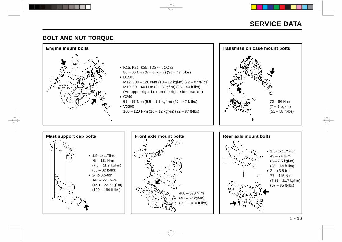
SERVICE DATA
5 - 16
BOLT AND NUT TORQUE
Engine mount bolts Transmission case mount bolts
Mast support cap bolts Front axle mount bolts Rear axle mount bolts
• K15, K21, K25, TD27-II, QD3250 – 60 N-m (5 – 6 kgf-m) (36 – 43 ft-lbs)
• D1503M12: 100 – 120 N-m (10 – 12 kgf-m) (72 – 87 ft-lbs)M10: 50 – 60 N-m (5 – 6 kgf-m) (36 – 43 ft-lbs)(An upper right bolt on the right-side bracket)
• C24055 – 65 N-m (5.5 – 6.5 kgf-m) (40 – 47 ft-lbs)
• V3300100 – 120 N-m (10 – 12 kgf-m) (72 – 87 ft-lbs)
• 1.5- to 1.75-ton75 – 111 N-m(7.6 – 11.3 kgf-m)(55 – 82 ft-lbs)
• 2- to 3.5-ton148 – 223 N-m(15.1 – 22.7 kgf-m)(109 – 164 ft-lbs)
400 – 570 N-m(40 – 57 kgf-m)(290 – 410 ft-lbs)
• 1.5- to 1.75-ton49 – 74 N-m(5 – 7.5 kgf-m)(36 – 54 ft-lbs)
• 2- to 3.5-ton77 – 115 N-m(7.85 – 11.7 kgf-m)(57 – 85 ft-lbs)
70 – 80 N-m(7 – 8 kgf-m)(51 – 58 ft-lbs)
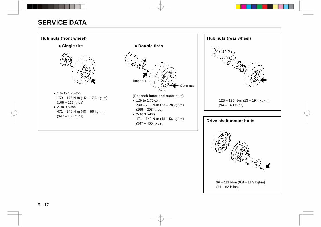
SERVICE DATA
5 - 17
Hub nuts (front wheel)
••••• Single tire ••••• Double tires
Hub nuts (rear wheel)
Drive shaft mount bolts
Inner nut
• 1.5- to 1.75-ton150 – 175 N-m (15 – 17.5 kgf-m)(108 – 127 ft-lbs)
• 2- to 3.5-ton471 – 549 N-m (48 – 56 kgf-m)(347 – 405 ft-lbs)
(For both inner and outer nuts)• 1.5- to 1.75-ton
230 – 280 N-m (23 – 28 kgf-m)(166 – 203 ft-lbs)
• 2- to 3.5-ton471 – 549 N-m (48 – 56 kgf-m)(347 – 405 ft-lbs)
128 – 190 N-m (13 – 19.4 kgf-m)(94 – 140 ft-lbs)
96 – 111 N-m (9.8 – 11.3 kgf-m)(71 – 82 ft-lbs)
Outer nut
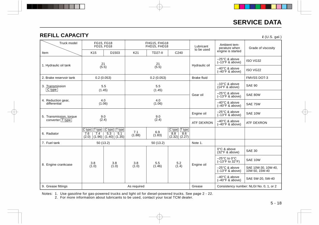
SERVICE DATA
5 - 18
REFILL CAPACITY (U.S. gal.)
Truck model FG15, FG18 FHG15, FHG18 Ambient tem-FD15, FD18 FHD15, FHD18 Lubricant perature when Grade of viscosity to be used engine is startedItem K15 D1503 K21 TD27-II C240
–25°C & above ISO VG3221 21 (–13°F & above)
1. Hydraulic oil tank (5.5) (5.5) Hydraulic oil–40°C & above ISO VG22(–40°F & above)
2. Brake reservoir tank 0.2 (0.053) 0.2 (0.053) Brake fluid FMVSS DOT-3
–10°C & above SAE 903. Transmission 5.5 5.5 (14°F & above) C type (1.45) (1.45)
Gear oil –25°C & above SAE 80W(–13°F & above)4. Reduction gear, 4.0 4.0
–40°C & above SAE 75Wdifferential (1.06) (1.06)(–40°F & above)
Engine oil –25°C & above SAE 10W5. Transmission, torque 9.0 9.0 (–13°F & above)
converter T type (2.4) (2.4)ATF DEXRON –40°C & above ATF DEXRON(–40°F & above)
C type T type C type T type7.1 6.9
C type T type6. Radiator 7.6 7.4 5.3 5.1 (1.88) (1.83) 8.8 8.6
(2.0) (1.96) (1.40) (1.35) (2.32) (2.27)
7. Fuel tank 50 (13.2) 50 (13.2) Note 1.
0°C & above SAE 30(32°F & above)
–25°C to 0°C SAE 10W(–13°F to 32°F)8. Engine crankcase 3.8 3.8 3.8 5.5 5.2 Engine oil(1.0) (1.0) (1.0) (1.46) (1.4) –25°C & above SAE 10W-30, 10W-40,
(–13°F & above) 10W-50, 15W-40
–40°C & above SAE 5W-20, 5W-40(–40°F & above)
9. Grease fittings As required Grease Consistency number: NLGI No. 0, 1, or 2
Notes: 1. Use gasoline for gas-powered trucks and light oil for diesel-powered trucks. See page 2 - 22.2. For more information about lubricants to be used, contact your local TCM dealer.
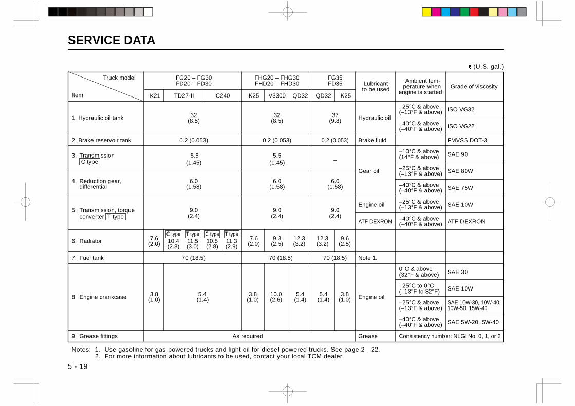
SERVICE DATA
5 - 19
(U.S. gal.)
Truck model FG20 – FG30 FHG20 – FHG30 FG35 Ambient tem-FD20 – FD30 FHD20 – FHD30 FD35 Lubricant perature when Grade of viscosityto be used engine is startedItem K21 TD27-II C240 K25 V3300 QD32 QD32 K25
–25°C & above ISO VG3232 32 37 (–13°F & above)
1. Hydraulic oil tank (8.5) (8.5) (9.8) Hydraulic oil–40°C & above ISO VG22(–40°F & above)
2. Brake reservoir tank 0.2 (0.053) 0.2 (0.053) 0.2 (0.053) Brake fluid FMVSS DOT-3
–10°C & above SAE 903. Transmission 5.5 5.5– (14°F & above)
C type (1.45) (1.45)
Gear oil –25°C & above SAE 80W(–13°F & above)4. Reduction gear, 6.0 6.0 6.0
–40°C & above SAE 75Wdifferential (1.58) (1.58) (1.58)(–40°F & above)
Engine oil –25°C & above SAE 10W5. Transmission, torque 9.0 9.0 9.0 (–13°F & above)
converter T type (2.4) (2.4) (2.4)ATF DEXRON –40°C & above ATF DEXRON(–40°F & above)
7.6C type T type C type T type
7.6 9.3 12.3 12.3 9.66. Radiator (2.0) 10.4 11.5 10.5 11.3 (2.0) (2.5) (3.2) (3.2) (2.5)(2.8) (3.0) (2.8) (2.9)
7. Fuel tank 70 (18.5) 70 (18.5) 70 (18.5) Note 1.
0°C & above SAE 30(32°F & above)
–25°C to 0°C SAE 10W(–13°F to 32°F)8. Engine crankcase 3.8 5.4 3.8 10.0 5.4 5.4 3.8 Engine oil(1.0) (1.4) (1.0) (2.6) (1.4) (1.4) (1.0) –25°C & above SAE 10W-30, 10W-40,
(–13°F & above) 10W-50, 15W-40
–40°C & above SAE 5W-20, 5W-40(–40°F & above)
9. Grease fittings As required Grease Consistency number: NLGI No. 0, 1, or 2
Notes: 1. Use gasoline for gas-powered trucks and light oil for diesel-powered trucks. See page 2 - 22.2. For more information about lubricants to be used, contact your local TCM dealer.
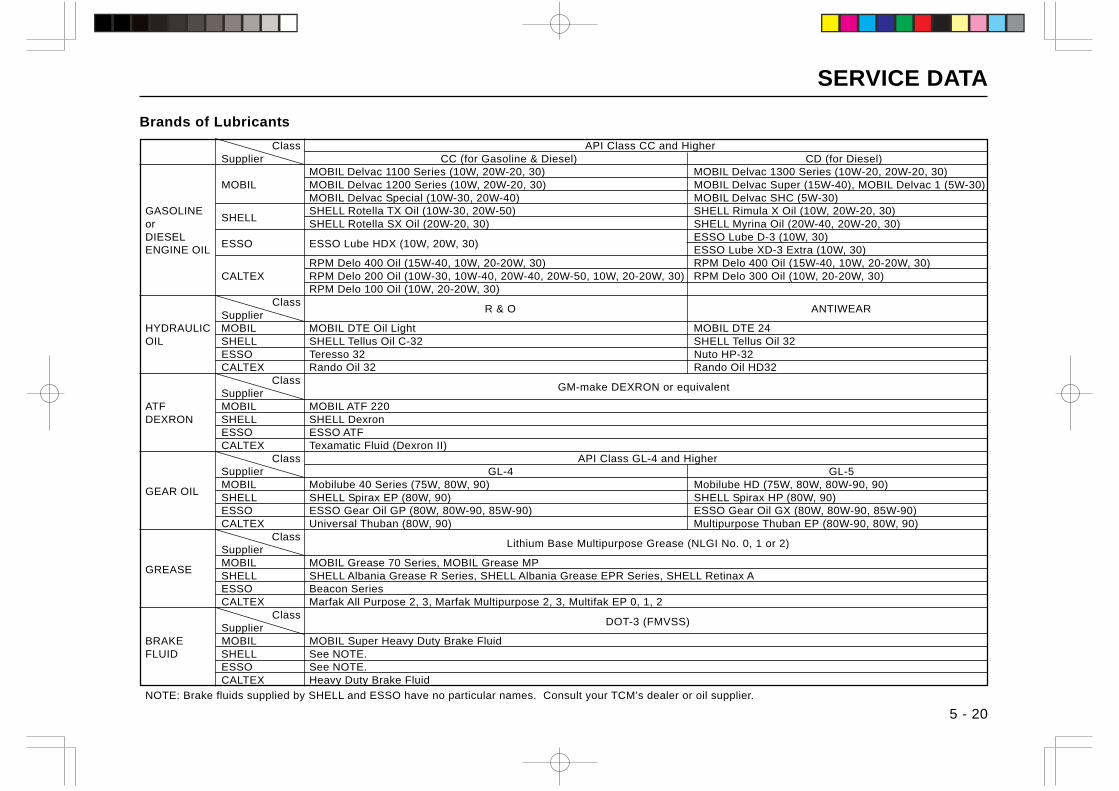
SERVICE DATA
5 - 20
Brands of Lubricants
Class API Class CC and HigherSupplier CC (for Gasoline & Diesel) CD (for Diesel)
MOBIL Delvac 1100 Series (10W, 20W-20, 30) MOBIL Delvac 1300 Series (10W-20, 20W-20, 30)MOBIL MOBIL Delvac 1200 Series (10W, 20W-20, 30) MOBIL Delvac Super (15W-40), MOBIL Delvac 1 (5W-30)
MOBIL Delvac Special (10W-30, 20W-40) MOBIL Delvac SHC (5W-30)GASOLINE
SHELLSHELL Rotella TX Oil (10W-30, 20W-50) SHELL Rimula X Oil (10W, 20W-20, 30)
or SHELL Rotella SX Oil (20W-20, 30) SHELL Myrina Oil (20W-40, 20W-20, 30)DIESEL
ESSO ESSO Lube HDX (10W, 20W, 30)ESSO Lube D-3 (10W, 30)
ENGINE OIL ESSO Lube XD-3 Extra (10W, 30)RPM Delo 400 Oil (15W-40, 10W, 20-20W, 30) RPM Delo 400 Oil (15W-40, 10W, 20-20W, 30)
CALTEX RPM Delo 200 Oil (10W-30, 10W-40, 20W-40, 20W-50, 10W, 20-20W, 30) RPM Delo 300 Oil (10W, 20-20W, 30)RPM Delo 100 Oil (10W, 20-20W, 30)
Class R & O ANTIWEAR
SupplierHYDRAULIC MOBIL MOBIL DTE Oil Light MOBIL DTE 24OIL SHELL SHELL Tellus Oil C-32 SHELL Tellus Oil 32
ESSO Teresso 32 Nuto HP-32CALTEX Rando Oil 32 Rando Oil HD32 Class
GM-make DEXRON or equivalentSupplier
ATF MOBIL MOBIL ATF 220DEXRON SHELL SHELL Dexron
ESSO ESSO ATFCALTEX Texamatic Fluid (Dexron II) Class API Class GL-4 and HigherSupplier GL-4 GL-5
GEAR OILMOBIL Mobilube 40 Series (75W, 80W, 90) Mobilube HD (75W, 80W, 80W-90, 90)SHELL SHELL Spirax EP (80W, 90) SHELL Spirax HP (80W, 90)ESSO ESSO Gear Oil GP (80W, 80W-90, 85W-90) ESSO Gear Oil GX (80W, 80W-90, 85W-90)CALTEX Universal Thuban (80W, 90) Multipurpose Thuban EP (80W-90, 80W, 90) Class
Lithium Base Multipurpose Grease (NLGI No. 0, 1 or 2)Supplier
GREASEMOBIL MOBIL Grease 70 Series, MOBIL Grease MPSHELL SHELL Albania Grease R Series, SHELL Albania Grease EPR Series, SHELL Retinax AESSO Beacon SeriesCALTEX Marfak All Purpose 2, 3, Marfak Multipurpose 2, 3, Multifak EP 0, 1, 2 Class
DOT-3 (FMVSS)Supplier
BRAKE MOBIL MOBIL Super Heavy Duty Brake FluidFLUID SHELL See NOTE.
ESSO See NOTE.CALTEX Heavy Duty Brake Fluid
NOTE: Brake fluids supplied by SHELL and ESSO have no particular names. Consult your TCM’s dealer or oil supplier.
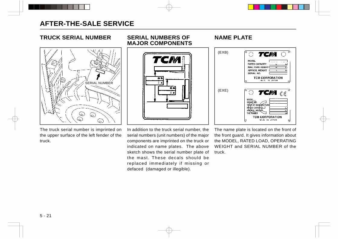
AFTER-THE-SALE SERVICE
5 - 21
TRUCK SERIAL NUMBER
The truck serial number is imprinted onthe upper surface of the left fender of thetruck.
SERIAL NUMBERS OFMAJOR COMPONENTS
In addition to the truck serial number, theserial numbers (unit numbers) of the majorcomponents are imprinted on the truck orindicated on name plates. The abovesketch shows the serial number plate ofthe mast . These decals should bereplaced immediately i f missing ordefaced (damaged or illegible).
SERIAL NUMBER
The name plate is located on the front ofthe front guard. It gives information aboutthe MODEL, RATED LOAD, OPERATINGWEIGHT and SERIAL NUMBER of thetruck.
NAME PLATE
(EXB)
(EXE)
MODELSERIAL NO.YEAR OF MANUFACTURERATED CAPACITYAPPROX. WEIGHTTHE POWER
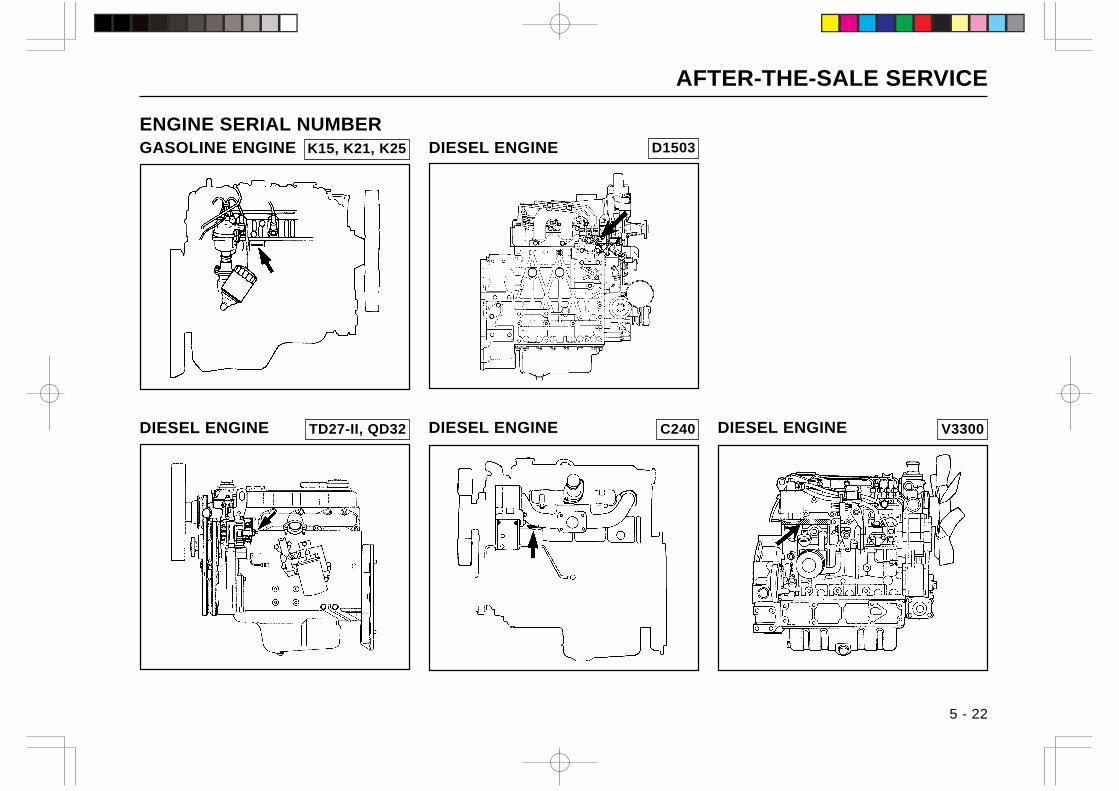
AFTER-THE-SALE SERVICE
DIESEL ENGINE
DIESEL ENGINE
ENGINE SERIAL NUMBERGASOLINE ENGINE
5 - 22
V3300 C240 TD27-II, QD32
K15, K21, K25
DIESEL ENGINE DIESEL ENGINE
D1503
AFTER-THE-SALE SERVICE
5 - 23
GENUINE TCM PARTSHowever excellent a part is, it is inevitablydeteriorates in performance with a long-time use. To ensure the best performanceof the lift truck, use genuine TCM’s partswhich are used for new trucks.When ordering spare parts, be sure todesignate TCM’s genuine parts.
GENUINE TCM LUBRICANTSUse genu ine TCM’s lubr icants fo rlubrication.
AFTER-THE-SALE SERVICE
5 - 24
WRITE DOWN DATA OF YOUR TRUCK HERE:
TRUCK
Model ..........................................................................
Truck Serial No. .........................................................
Service Weight ............................................. kg (lbs)
Max. Load ............... mm (in.): .................... kg (lbs)
ENGINE
Manufacturer ..............................................................
Model ..........................................................................
Engine Serial No. .......................................................
DATE OF PURCHASE .....................................................................................................................................................
DEALER’S NAME ................................................................. PHONE .....................................................................
DEALER’S ADDRESS .....................................................................................................................................................

MEMO
dJ E ・E ・E ・.-=!I I I I ベト l - ・E ・E ・. I I ・・ |二
十 十
1-¥ ベト ¥-F
6. INDEX
CONTENTS
0 - 9 ........................................................................................ 6-1A - F ....................................................................................... 6-1F - O ....................................................................................... 6-2O - S ...................................................................................... 6-3T - W ...................................................................................... 6-4
0 - 9
3 MONTHS (600 OPERATING HOURS) CHECKS .......... 4-39
6 MONTHS (1200 OPERATING HOURS) CHECKS ........ 4-41
A
ACCELERATOR PEDAL .................................................... 2-15
ADJUSTING OPERATING FORCE OF PARKING
BRAKE LEVER ................................................................... 4-30
AIR BLEEDING FUEL SYSTEM ........................................ 4-24
AIR CLEANER CLOGGING WARNING LIGHT .................. 2-9
ANNUAL (2400 OPERATING HOURS) CHECKS............. 4-42
B
BASIC LOAD CENTER AND RATED LOAD ....................... 3-2
BATTERY ............................................................................ 2-21
BATTERY ELECTROLYTE LEVEL WARNING LIGHT ..... 2-10
BEACON LIGHT ................................................................. 2-26
BOLT AND NUT TORQUE .................................................. 5-16
BRAKE AND CLUTCH FLUID RESERVOIR ..................... 2-21
BRAKE PEDAL ................................................................... 2-15
C
CAUTION PLATES ............................................................. 1-41
CHANGING ENGINE OIL ................................................... 4-34
CHANGING ENGINE OIL FILTER ..................................... 4-35
CHANGING FUEL FILTER ................................................. 4-40
CHARGE WARNING LIGHT .............................................. 2-10
CHECKING AND CLEANING AIR CLEANER
ELEMENT ............................................................................ 4-33
CLEANING FUEL FILTER .................................................. 4-40
CLUTCH PEDAL ................................................................. 2-15
COMBINATION LEVER ........................................................ 2-6
COOLING WATER TEMPERATURE GAUGE ..................... 2-8
D
DIRECTIONAL SHIFT LEVER ........................................... 2-13
DOCUMENT POCKET ....................................................... 2-17
DRAWBAR .......................................................................... 2-20
DURING BREAK-IN .............................................................. 3-1
E
ENGINE HOOD ................................................................... 2-18
ENGINE HOOD STOPPER ................................................ 2-19
ENGINE OIL PRESSURE WARNING LIGHT ..................... 2-9
ENGINE ROOM .................................................................. 4-17
ENGINE SERIAL NUMBER................................................ 5-22
EQUIPMENT ....................................................................... 5-13
F
FIRE EXTINGUISHER (FE) ............................................... 2-26
FOR SUPERVISORS ........................................................... 1-1
FORK LOCK BOLT ............................................................. 2-20
0 - 9 / A - F
6-1
FORK STOPPER ................................................................ 2-19
FUEL GAUGE ....................................................................... 2-8
FUEL LEVEL WARNING LIGHT .......................................... 2-9
FUEL TANK CAP ................................................................ 2-22
FUSE BOX .......................................................................... 2-21
FUSIBLE LINK (MAIN FUSE) ............................................ 4-26
G
GENUINE TCM LUBRICANTS........................................... 5-23
GENUINE TCM PARTS ...................................................... 5-23
GLOVE BOX........................................................................ 2-17
GLOW INDICATOR............................................................... 2-9
GREASING POINTS........................................................... 4-37
H
HIGH LOAD BACKREST (HBR) ........................................ 2-26
HORN BUTTON .................................................................... 2-6
HOUR METER ...................................................................... 2-8
HOW THE LIFT TRUCK WORKS? .................................... 1-14
HYDRAULIC OIL TANK CAP ............................................. 2-23
I
INCHING PEDAL ................................................................ 2-15
INSPECTION AND SERVICE ............................................ 1-31
INSTRUMENTS AND CONTROLS ...................................... 2-3
INTERLOCK SYSTEM........................................................ 2-11
L
LEVERS AND PEDALS ...................................................... 2-12
LIFT LEVER ........................................................................ 2-12
LIGHTING SWITCH .............................................................. 2-6
LIGHTS AND LAMPS ......................................................... 2-24
LOAD BACKREST .............................................................. 2-18
LOAD CHART ..................................................................... 5-14
LOAD HANDLING ............................................................... 1-24
LOAD HANDLING ............................................................... 3-13
LUBRICATING LIFT CHAIN ............................................... 4-36
M
MAGAZINE BOX ................................................................. 2-17
MEASURES AGAINST COLD OR HOT WEATHER ......... 3-10
METERS AND WARNING LIGHTS...................................... 2-7
MONTHLY (200 OPERATING HOURS) CHECKS ............ 4-32
N
NAME PLATE ...................................................................... 5-21
NEUTRAL LAMP ................................................................... 2-9
O
OPERATING LIFT TRUCK ................................................... 3-4
OPERATOR’S SEAT ........................................................... 2-16
OPTIONAL EQUIPMENT ................................................... 2-26
F - O
6-2
OVERHEAD GUARD .......................................................... 2-17
OVERHEAD GUARD WITH WIRE NETTING ................... 2-26
P
PARKING ............................................................................. 1-29
PARKING BRAKE LEVER .................................................. 2-14
PARKING BRAKE WARNING LIGHT .................................. 2-9
PERIODIC INSPECTION ................................................... 4-31
PERIODICAL REPLACEMENT OF SAFETY PARTS ....... 4-31
PICTORIAL NOMENCLATURE ............................................ 2-1
PNEUMATIC SHAPED CUSHION TIRE
(UNIQUE TIRE, TR01) ....................................................... 2-26
POWER BRAKE (POB) ...................................................... 2-26
PREOPERATIONAL CHECKS ............................................. 4-1
PREVENTIVE MAINTENANCE ......................................... 4-17
PREVENTIVE MAINTENANCE SCHEDULE .................... 4-43
PROPER OPERATION ......................................................... 3-1
R
RADIATOR .......................................................................... 2-23
RADIATOR RESERVOIR TANK ......................................... 2-23
RADIATOR WATER LEVEL WARNING LIGHT ................. 2-10
REAR WORK LIGHT (RWL) .............................................. 2-26
REFILL CAPACITY ............................................................. 5-18
RELATIONSHIP BETWEEN LOAD AND
STABILITY OF TRUCK ......................................................... 3-1
REMOVING WATER FROM SEDIMENTER ..................... 4-22
REPLACING FUSES .......................................................... 4-26
REPLACING LAMP BULBS ............................................... 4-28
REPLACING TIRES AND REPAIRING FLAT TIRE .......... 4-27
S
SAFETY STEP AND HAND GRIP...................................... 2-20
SEAT BELT .......................................................................... 2-16
SEAT BELT WARNING LIGHT ............................................. 2-9
SEDIMENTER WARNING LIGHT ...................................... 2-10
SERIAL NUMBERS OF MAJOR COMPONENTS ............ 5-21
SERVICE DATA .................................................................. 5-15
SHIFT LEVER ..................................................................... 2-13
SIDEVIEW MIRRORS ........................................................ 2-24
SOUND VOLUME-ADJUSTABLE BACK-UP BUZZER..... 2-26
SPECIFICATIONS ................................................................ 5-1
SPEED ALARM SYSTEM (SAS)........................................ 2-26
SPEED RANGE SHIFT LEVER ......................................... 2-13
SPEEDOMETER (SM)........................................................ 2-26
STABILITY OF LIFT TRUCK ................................................ 3-3
STARTER SWITCH .............................................................. 2-5
STARTING THE ENGINE WITH AUXILIARY BATTERY .. 4-29
STEERING COLUMN TILT LEVER ................................... 2-14
STEERING WHEEL ............................................................ 2-14
STORING ............................................................................ 3-15
SWITCHES.......................................................................... 2-27
SWITCHES............................................................................ 2-5
O - S
6-3

T
TILT LEVER......................................................................... 2-12
TIRE CHAIN (TC) ............................................................... 2-26
TORQUE CONVERTER OIL FILLER ................................ 2-24
TRANSPORTING LIFT TRUCK ........................................... 3-4
TRAVELING ........................................................................ 1-17
TRAVELING AND LOAD HANDLING INTERLOCK
SYSTEM .............................................................................. 2-11
TRAVELING AND LOAD HANDLING INTERLOCK
SYSTEM WARNING LIGHT ................................................. 2-9
TRAVELING AND STARTING ON A SLOPE ....................... 3-3
TRUCK BODY ..................................................................... 2-16
TRUCK SERIAL NUMBER ................................................. 5-21
U
USING INCHING PEDAL ..................................................... 3-3
W
WRITE DOWN DATA OF YOUR TRUCK HERE ............... 5-24
T - W
6-4
ISSUED: DEC., 2005REVISED: MAY, 2006REVISED: FEB., 2007REVISED: OCT., 2007REVISED: MAR., 2009
MARKETING GROUP: 1-15-5, Nishi-shimbashi, Minato-ku, Tokyo105-0003, Japan
FAX: Japan +81-3-35918154
All rights reserved JB-0903100(F) Printed in Japan
No. OF-2B0EE

dJ E ・E ・E ・.-=!I I I I ベト l - ・E ・E ・. I I ・・ |二
十 十
1-¥ ベト ¥-F