for Characterizing Enzyme Reactions in Confined Space 𝐿 ...
11
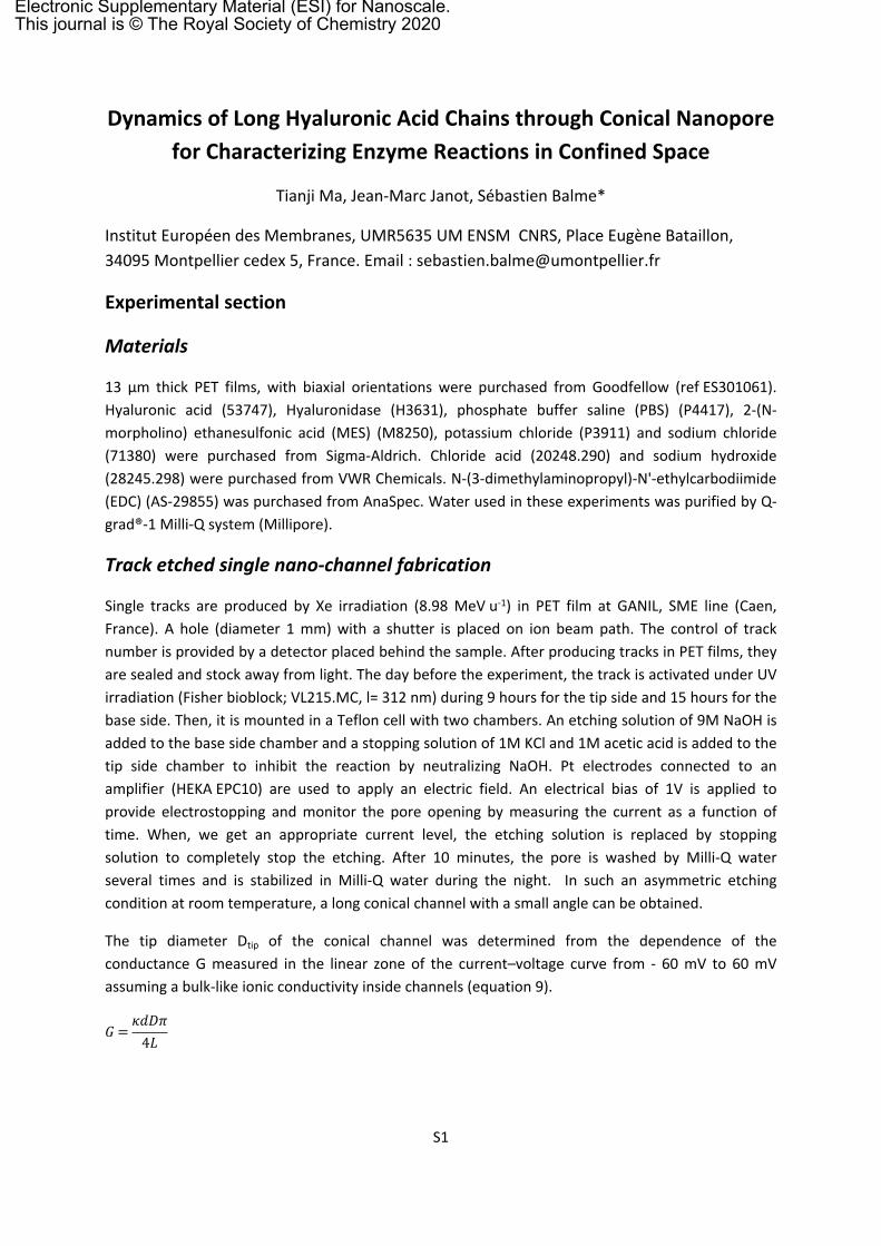
S1 Dynamics of Long Hyaluronic Acid Chains through Conical Nanopore for Characterizing Enzyme Reactions in Confined Space Tianji Ma, Jean-Marc Janot, Sébastien Balme* Institut Européen des Membranes, UMR5635 UM ENSM CNRS, Place Eugène Bataillon, 34095 Montpellier cedex 5, France. Email : [email protected] Experimental section Materials 13 μm thick PET films, with biaxial orientations were purchased from Goodfellow (ref ES301061). Hyaluronic acid (53747), Hyaluronidase (H3631), phosphate buffer saline (PBS) (P4417), 2-(N- morpholino) ethanesulfonic acid (MES) (M8250), potassium chloride (P3911) and sodium chloride (71380) were purchased from Sigma-Aldrich. Chloride acid (20248.290) and sodium hydroxide (28245.298) were purchased from VWR Chemicals. N-(3-dimethylaminopropyl)-N'-ethylcarbodiimide (EDC) (AS-29855) was purchased from AnaSpec. Water used in these experiments was purified by Q- grad®-1 Milli-Q system (Millipore). Track etched single nano-channel fabrication Single tracks are produced by Xe irradiation (8.98 MeV u -1 ) in PET film at GANIL, SME line (Caen, France). A hole (diameter 1 mm) with a shutter is placed on ion beam path. The control of track number is provided by a detector placed behind the sample. After producing tracks in PET films, they are sealed and stock away from light. The day before the experiment, the track is activated under UV irradiation (Fisher bioblock; VL215.MC, l= 312 nm) during 9 hours for the tip side and 15 hours for the base side. Then, it is mounted in a Teflon cell with two chambers. An etching solution of 9M NaOH is added to the base side chamber and a stopping solution of 1M KCl and 1M acetic acid is added to the tip side chamber to inhibit the reaction by neutralizing NaOH. Pt electrodes connected to an amplifier (HEKA EPC10) are used to apply an electric field. An electrical bias of 1V is applied to provide electrostopping and monitor the pore opening by measuring the current as a function of time. When, we get an appropriate current level, the etching solution is replaced by stopping solution to completely stop the etching. After 10 minutes, the pore is washed by Milli-Q water several times and is stabilized in Milli-Q water during the night. In such an asymmetric etching condition at room temperature, a long conical channel with a small angle can be obtained. The tip diameter D tip of the conical channel was determined from the dependence of the conductance G measured in the linear zone of the current–voltage curve from - 60 mV to 60 mV assuming a bulk-like ionic conductivity inside channels (equation 9). = 4 Electronic Supplementary Material (ESI) for Nanoscale. This journal is © The Royal Society of Chemistry 2020
Transcript of for Characterizing Enzyme Reactions in Confined Space 𝐿 ...
S1
Dynamics of Long Hyaluronic Acid Chains through Conical Nanopore for Characterizing Enzyme Reactions in Confined Space
Tianji Ma, Jean-Marc Janot, Sébastien Balme*
Institut Européen des Membranes, UMR5635 UM ENSM CNRS, Place Eugène Bataillon, 34095 Montpellier cedex 5, France. Email : [email protected]
Experimental section
Materials
13 μm thick PET films, with biaxial orientations were purchased from Goodfellow (ref ES301061). Hyaluronic acid (53747), Hyaluronidase (H3631), phosphate buffer saline (PBS) (P4417), 2-(N-morpholino) ethanesulfonic acid (MES) (M8250), potassium chloride (P3911) and sodium chloride (71380) were purchased from Sigma-Aldrich. Chloride acid (20248.290) and sodium hydroxide (28245.298) were purchased from VWR Chemicals. N-(3-dimethylaminopropyl)-N'-ethylcarbodiimide (EDC) (AS-29855) was purchased from AnaSpec. Water used in these experiments was purified by Q-grad®-1 Milli-Q system (Millipore).
Track etched single nano-channel fabrication
Single tracks are produced by Xe irradiation (8.98 MeV u-1) in PET film at GANIL, SME line (Caen, France). A hole (diameter 1 mm) with a shutter is placed on ion beam path. The control of track number is provided by a detector placed behind the sample. After producing tracks in PET films, they are sealed and stock away from light. The day before the experiment, the track is activated under UV irradiation (Fisher bioblock; VL215.MC, l= 312 nm) during 9 hours for the tip side and 15 hours for the base side. Then, it is mounted in a Teflon cell with two chambers. An etching solution of 9M NaOH is added to the base side chamber and a stopping solution of 1M KCl and 1M acetic acid is added to the tip side chamber to inhibit the reaction by neutralizing NaOH. Pt electrodes connected to an amplifier (HEKA EPC10) are used to apply an electric field. An electrical bias of 1V is applied to provide electrostopping and monitor the pore opening by measuring the current as a function of time. When, we get an appropriate current level, the etching solution is replaced by stopping solution to completely stop the etching. After 10 minutes, the pore is washed by Milli-Q water several times and is stabilized in Milli-Q water during the night. In such an asymmetric etching condition at room temperature, a long conical channel with a small angle can be obtained.
The tip diameter Dtip of the conical channel was determined from the dependence of the conductance G measured in the linear zone of the current–voltage curve from - 60 mV to 60 mV assuming a bulk-like ionic conductivity inside channels (equation 9).
𝐺=
𝜅𝑑𝐷𝜋4𝐿
Electronic Supplementary Material (ESI) for Nanoscale.This journal is © The Royal Society of Chemistry 2020
S2
where, κ is the ionic conductivity of the solution, L is the channel length (13 μm) and Dbase is the base diameter which was calculated from the total etching time t using the relationship Dbase = 2.5t (the factor 2.5 was determined in our experimental set up using multipore track-etched membranes).
The current-voltage curves were obtained from the current traces recorded as a function of time from 1 V to -1 V by steps of 100 mV for 2 s and from 100 mV to -100 mV by steps of 10 mV for 2 s using a sampling rate 50 kHz. Ag/AgCl electrodes were used for the measurements. For conductance measurement to determine tip diameter, a solution of NaCl at 1 M was used.
Recording of hyaluronic acid translocation
Hyaluronic acid translocations were recorded using the same amplifier (HEKA EPC10). The sampling rate is 100 kHz and a built-in low-pass filter at 10 kHz is used. Data analysis for event detection is performed using a custom-made LabView software with butterworth filter of 5 KHz, 3 orders and Savitzky-Golay filter of 1200 side points, 1 order. We take 5σ to detect events.
Enzyme immobilization
The hyaluronidase immobilization inside the channel was performed in situ. The two chambers of the cell containing the channel membrane were filled with a solution containing 0.1 M KCl, 0.1 M MES at pH 4.7. The pH of the solution was adjusted using HCl and NaOH solutions. The hyaluronidase was then added in cis chamber (tip side of the channel) or in the trans-chamber (base side of the channel) according to the need. At the end, 50 mM of EDC was added in both two chambers. The reaction was during the whole night for a maximum grafting. Then, the channel was well rinsed by Milli-Q water and then stabilized in PBS buffer for 1 hour.
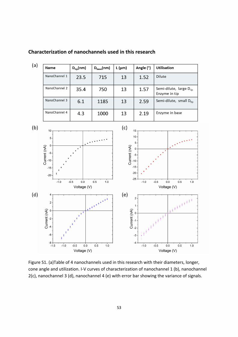
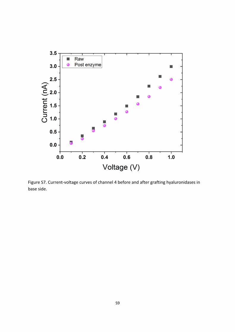
I-V curves of the channel before and after enzyme immobilization was recorded in PBS buffer with 1M of NaCl shown in Figure S1. The change of rectification and conductance can be the evidence of the enzyme grafting.
S3
Characterization of nanochannels used in this research
Figure S1. (a)Table of 4 nanochannels used in this research with their diameters, longer, cone angle and utilization. I-V curves of characterization of nanochannel 1 (b), nanochannel 2(c), nanochannel 3 (d), nanochannel 4 (e) with error bar showing the variance of signals.
S4
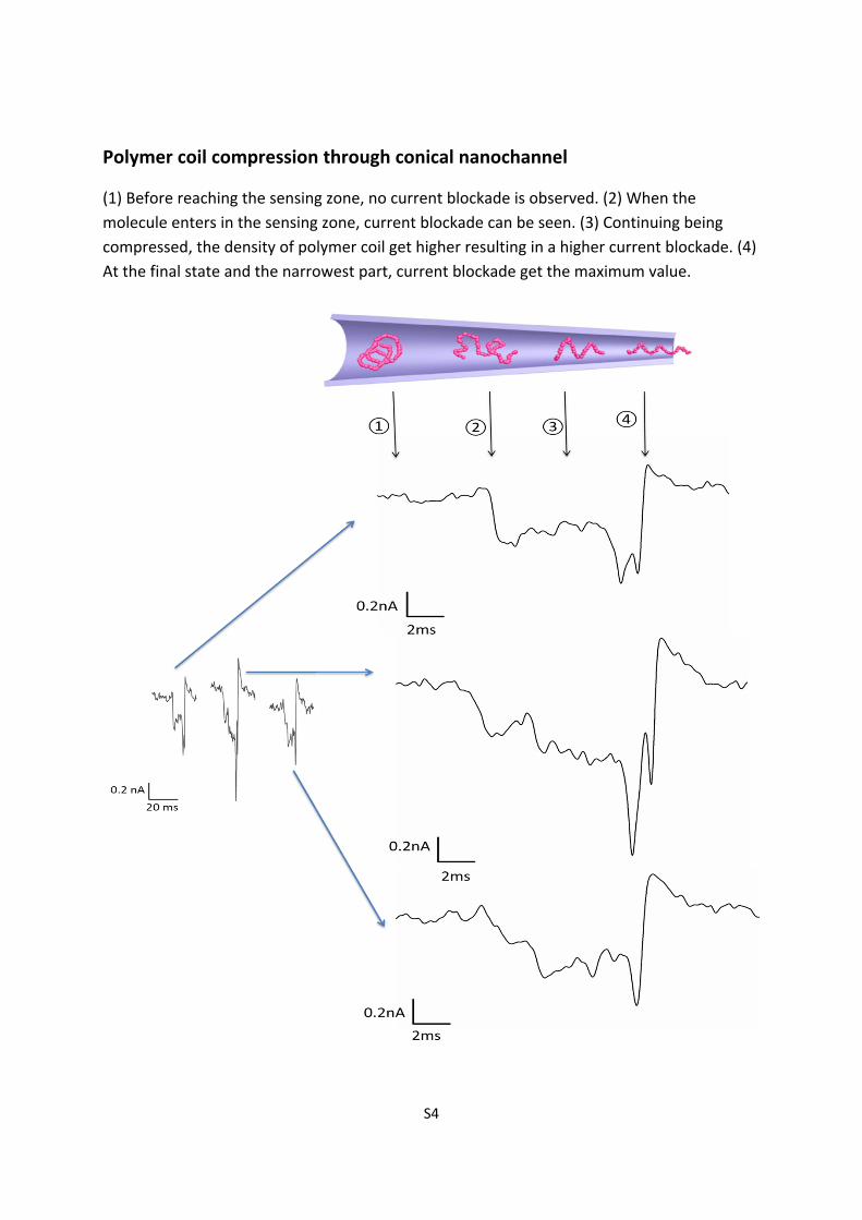
Polymer coil compression through conical nanochannel
(1) Before reaching the sensing zone, no current blockade is observed. (2) When the molecule enters in the sensing zone, current blockade can be seen. (3) Continuing being compressed, the density of polymer coil get higher resulting in a higher current blockade. (4) At the final state and the narrowest part, current blockade get the maximum value.
S5
Figure S2. Sketch of compression procedure of polymer molecules passing through a conical nanochannel compared with three examples of peak.
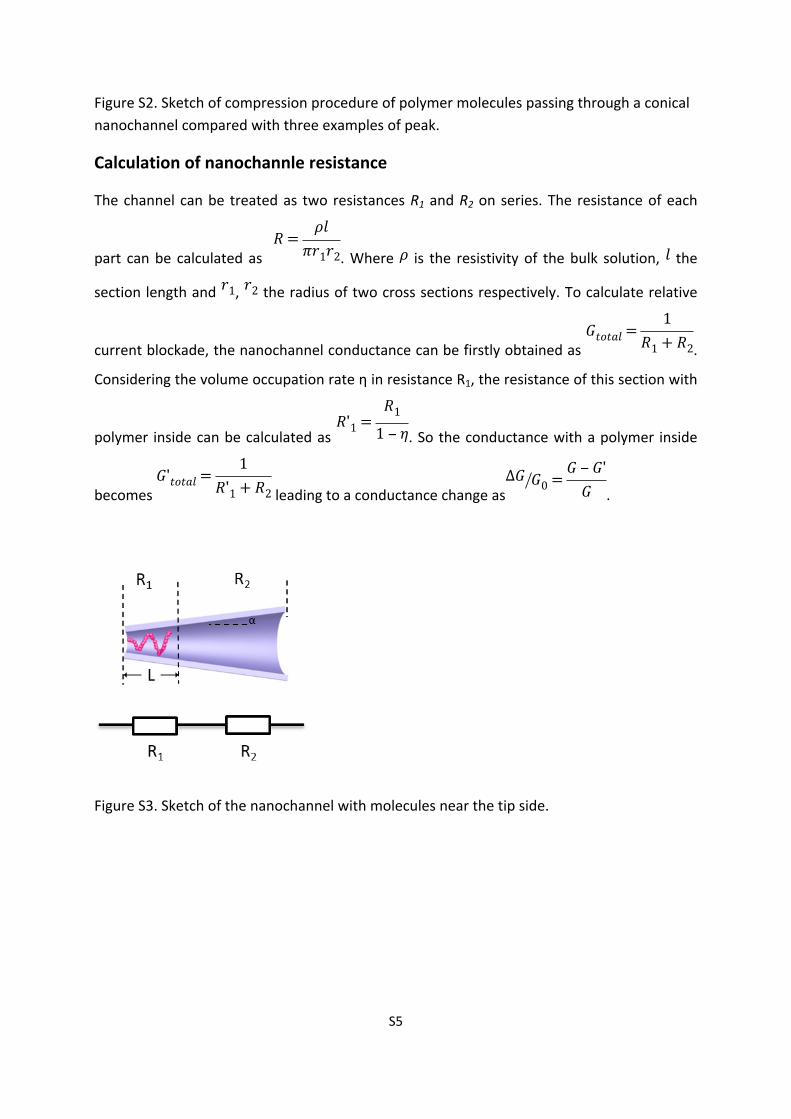
Calculation of nanochannle resistance
The channel can be treated as two resistances R1 and R2 on series. The resistance of each
part can be calculated as . Where is the resistivity of the bulk solution, the 𝑅=
𝜌𝑙𝜋𝑟1𝑟2 𝜌 𝑙
section length and , the radius of two cross sections respectively. To calculate relative 𝑟1 𝑟2
current blockade, the nanochannel conductance can be firstly obtained as . 𝐺𝑡𝑜𝑡𝑎𝑙=
1𝑅1 + 𝑅2
Considering the volume occupation rate η in resistance R1, the resistance of this section with
polymer inside can be calculated as . So the conductance with a polymer inside 𝑅'1 =
𝑅11 ‒ 𝜂
becomes leading to a conductance change as .𝐺'𝑡𝑜𝑡𝑎𝑙=
1𝑅'1 + 𝑅2
Δ𝐺 𝐺0 =𝐺 ‒ 𝐺'𝐺
Figure S3. Sketch of the nanochannel with molecules near the tip side.
S6
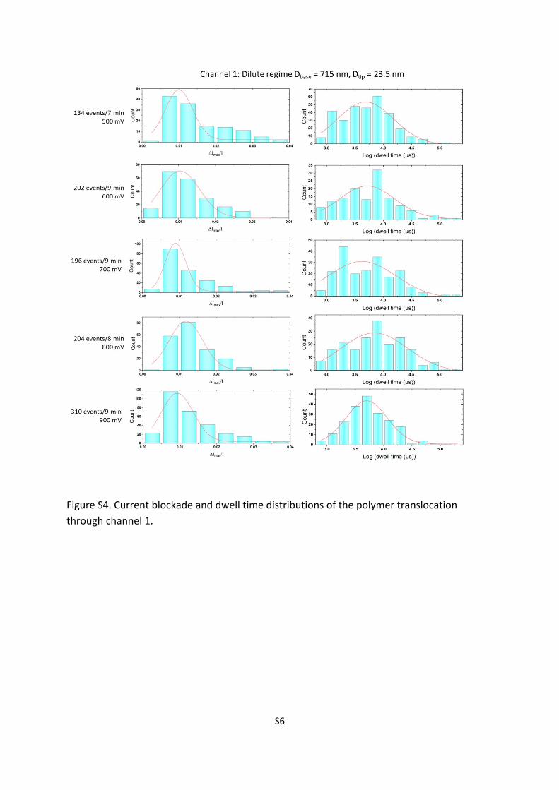
Figure S4. Current blockade and dwell time distributions of the polymer translocation through channel 1.
S7
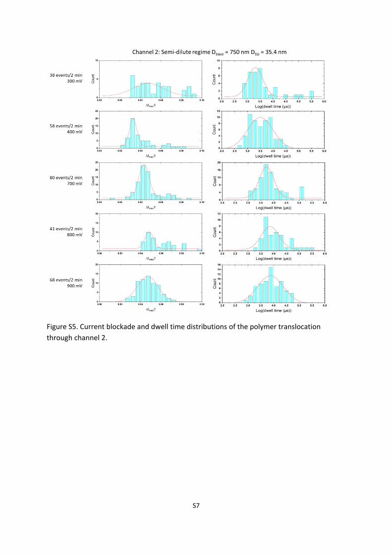
Figure S5. Current blockade and dwell time distributions of the polymer translocation through channel 2.
S8
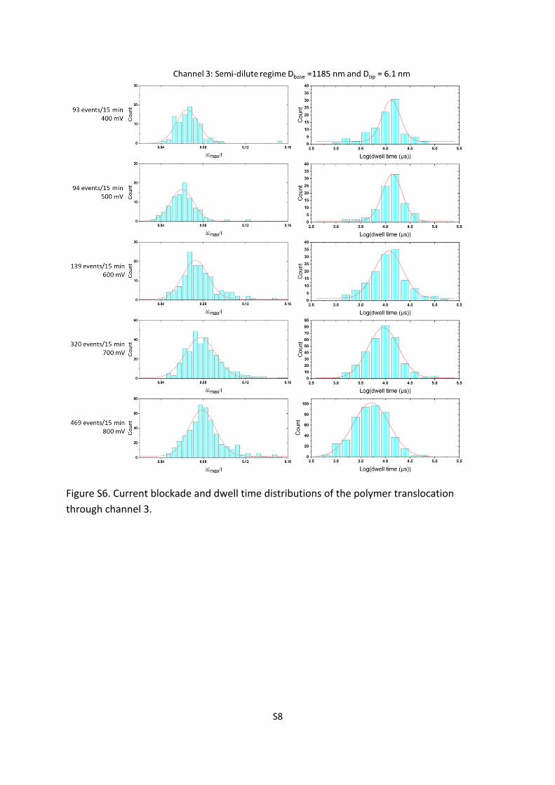
Figure S6. Current blockade and dwell time distributions of the polymer translocation through channel 3.
S9
Figure S7. Current-voltage curves of channel 4 before and after grafting hyaluronidases in base side.
S10
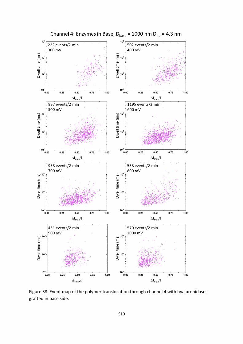
Figure S8. Event map of the polymer translocation through channel 4 with hyaluronidases grafted in base side.
S11
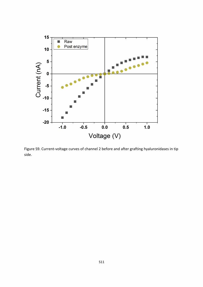
Figure S9. Current-voltage curves of channel 2 before and after grafting hyaluronidases in tip side.