
Flowmeter Promag 10W-Electromagnetic-Water and Waste Water
32
TI093D/06/en/08.09 71101434 Technical Information Proline Promag 10W Electromagnetic Flow Measuring System Flow measurement of liquids in water or wastewater applications Application Electromagnetic flowmeter for bidirectional measurement of liquids with a minimum conductivity of ≥ 50 μS/cm: • Drinking water • Wastewater • Sewage sludge • Flow measurement up to 110000 m³/h • Fluid temperature up to +80 °C • Process pressures up to 40 bar • Lengths in accordance with DVGW/ISO Application-specific lining materials: • Polyurethane and hard rubber Lined measuring pipes with materials approved for drinking water: • KTW, WRAS, NSF, ACS, etc. Your benefits Promag measuring devices offer you cost-effective flow measurement with a high degree of accuracy for a wide range of process conditions. The uniform Proline transmitter concept comprises: • High degree of reliability and measuring stability • Uniform operating concept The tried-and-tested Promag sensors offer: • No pressure loss • Not sensitive to vibrations • Simple installation and commissioning
-
Upload
edress-hauser-flow-meter-level-pressure-temperature -
Category
Technology
-
view
614 -
download
5
Transcript of Flowmeter Promag 10W-Electromagnetic-Water and Waste Water

TI093D/06/en/08.09
71101434
Technical Information
Proline Promag 10WElectromagnetic Flow Measuring System
Flow measurement of liquids in water or wastewater applications
Application
Electromagnetic flowmeter for bidirectional
measurement of liquids with a minimum
conductivity of ≥ 50 μS/cm:
• Drinking water
• Wastewater
• Sewage sludge
• Flow measurement up to 110000 m³/h
• Fluid temperature up to +80 °C
• Process pressures up to 40 bar
• Lengths in accordance with DVGW/ISO
Application-specific lining materials:
• Polyurethane and hard rubber
Lined measuring pipes with materials approved for
drinking water:
• KTW, WRAS, NSF, ACS, etc.
Your benefits
Promag measuring devices offer you cost-effective
flow measurement with a high degree of accuracy
for a wide range of process conditions.
The uniform Proline transmitter concept comprises:
• High degree of reliability and measuring stability
• Uniform operating concept
The tried-and-tested Promag sensors offer:
• No pressure loss
• Not sensitive to vibrations
• Simple installation and commissioning
Proline Promag 10 W
2 Endress + Hauser
Table of contents
Function and system design. . . . . . . . . . . . . . . . . . . . . 3
Measuring principle . . . . . . . . . . . . . . . . . . . . . . . . . . . . . . . . . . . 3
Measuring system . . . . . . . . . . . . . . . . . . . . . . . . . . . . . . . . . . . . . 3
Input . . . . . . . . . . . . . . . . . . . . . . . . . . . . . . . . . . . . . . 3
Measured variable . . . . . . . . . . . . . . . . . . . . . . . . . . . . . . . . . . . . 3
Measuring ranges . . . . . . . . . . . . . . . . . . . . . . . . . . . . . . . . . . . . . 3
Operable flow range . . . . . . . . . . . . . . . . . . . . . . . . . . . . . . . . . . . 3
Output . . . . . . . . . . . . . . . . . . . . . . . . . . . . . . . . . . . . . 4
Output signal . . . . . . . . . . . . . . . . . . . . . . . . . . . . . . . . . . . . . . . . 4
Signal on alarm . . . . . . . . . . . . . . . . . . . . . . . . . . . . . . . . . . . . . . 4
Load . . . . . . . . . . . . . . . . . . . . . . . . . . . . . . . . . . . . . . . . . . . . . . 4
Low flow cut off . . . . . . . . . . . . . . . . . . . . . . . . . . . . . . . . . . . . . . 4
Galvanic isolation . . . . . . . . . . . . . . . . . . . . . . . . . . . . . . . . . . . . . 4
Power supply. . . . . . . . . . . . . . . . . . . . . . . . . . . . . . . . 4
Electrical connection, measuring unit . . . . . . . . . . . . . . . . . . . . . 4
Electrical connection, terminal assignment . . . . . . . . . . . . . . . . . 5
Electrical connection, remote version . . . . . . . . . . . . . . . . . . . . . 5
Supply voltage (power supply) . . . . . . . . . . . . . . . . . . . . . . . . . . . 5
Cable entry . . . . . . . . . . . . . . . . . . . . . . . . . . . . . . . . . . . . . . . . . 5
Remote version cable specifications . . . . . . . . . . . . . . . . . . . . . . . 6
Power consumption . . . . . . . . . . . . . . . . . . . . . . . . . . . . . . . . . . . 6
Power supply failure . . . . . . . . . . . . . . . . . . . . . . . . . . . . . . . . . . . 6
Potential equalization . . . . . . . . . . . . . . . . . . . . . . . . . . . . . . . . . . 7
Performance characteristics. . . . . . . . . . . . . . . . . . . . . 9
Reference operating conditions . . . . . . . . . . . . . . . . . . . . . . . . . . . 9
Maximum measured error . . . . . . . . . . . . . . . . . . . . . . . . . . . . . . 9
Repeatability . . . . . . . . . . . . . . . . . . . . . . . . . . . . . . . . . . . . . . . . . 9
Operating conditions: Installations . . . . . . . . . . . . . . 10
Installation instructions . . . . . . . . . . . . . . . . . . . . . . . . . . . . . . . . 10
Inlet and outlet run . . . . . . . . . . . . . . . . . . . . . . . . . . . . . . . . . . 13
Adapters . . . . . . . . . . . . . . . . . . . . . . . . . . . . . . . . . . . . . . . . . . . 13
Length of connecting cable . . . . . . . . . . . . . . . . . . . . . . . . . . . . . 14
Operating conditions: Environment . . . . . . . . . . . . . 15
Ambient temperature range . . . . . . . . . . . . . . . . . . . . . . . . . . . . 15
Storage temperature . . . . . . . . . . . . . . . . . . . . . . . . . . . . . . . . . . 15
Degree of protection . . . . . . . . . . . . . . . . . . . . . . . . . . . . . . . . . . 15
Shock and vibration resistance . . . . . . . . . . . . . . . . . . . . . . . . . . 15
Electromagnetic compatibility (EMC) . . . . . . . . . . . . . . . . . . . . . 15
Operating conditions: Process . . . . . . . . . . . . . . . . . . 16
Medium temperature range . . . . . . . . . . . . . . . . . . . . . . . . . . . . 16
Conductivity . . . . . . . . . . . . . . . . . . . . . . . . . . . . . . . . . . . . . . . 16
Medium pressure range
(nominal pressure) . . . . . . . . . . . . . . . . . . . . . . . . . . . . . . . . . . 16
Pressure tightness . . . . . . . . . . . . . . . . . . . . . . . . . . . . . . . . . . . . 16
Limiting flow . . . . . . . . . . . . . . . . . . . . . . . . . . . . . . . . . . . . . . . 17
Pressure loss . . . . . . . . . . . . . . . . . . . . . . . . . . . . . . . . . . . . . . . . 18
Mechanical construction . . . . . . . . . . . . . . . . . . . . . . 19
Measuring tube specifications . . . . . . . . . . . . . . . . . . . . . . . . . . . 19
Design, dimensions . . . . . . . . . . . . . . . . . . . . . . . . . . . . . . . . . . 20
Weight . . . . . . . . . . . . . . . . . . . . . . . . . . . . . . . . . . . . . . . . . . . 26
Material . . . . . . . . . . . . . . . . . . . . . . . . . . . . . . . . . . . . . . . . . . . 27
Material load diagram . . . . . . . . . . . . . . . . . . . . . . . . . . . . . . . 27
Fitted electrodes . . . . . . . . . . . . . . . . . . . . . . . . . . . . . . . . . . . . 29
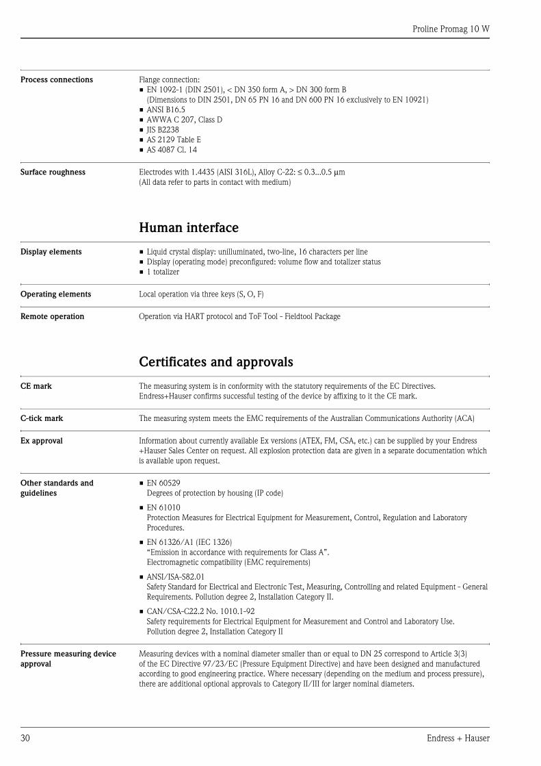
Process connections . . . . . . . . . . . . . . . . . . . . . . . . . . . . . . . . . . 30
Surface roughness . . . . . . . . . . . . . . . . . . . . . . . . . . . . . . . . . . . 30
Human interface . . . . . . . . . . . . . . . . . . . . . . . . . . . . 30
Display elements . . . . . . . . . . . . . . . . . . . . . . . . . . . . . . . . . . . . 30
Operating elements . . . . . . . . . . . . . . . . . . . . . . . . . . . . . . . . . . 30
Remote operation . . . . . . . . . . . . . . . . . . . . . . . . . . . . . . . . . . . . 30
Certificates and approvals . . . . . . . . . . . . . . . . . . . . . 30
CE mark . . . . . . . . . . . . . . . . . . . . . . . . . . . . . . . . . . . . . . . . . . 30
C-tick mark . . . . . . . . . . . . . . . . . . . . . . . . . . . . . . . . . . . . . . . 30
Ex approval . . . . . . . . . . . . . . . . . . . . . . . . . . . . . . . . . . . . . . . . 30
Other standards and guidelines . . . . . . . . . . . . . . . . . . . . . . . . . . 30
Pressure measuring device approval . . . . . . . . . . . . . . . . . . . . . . 30
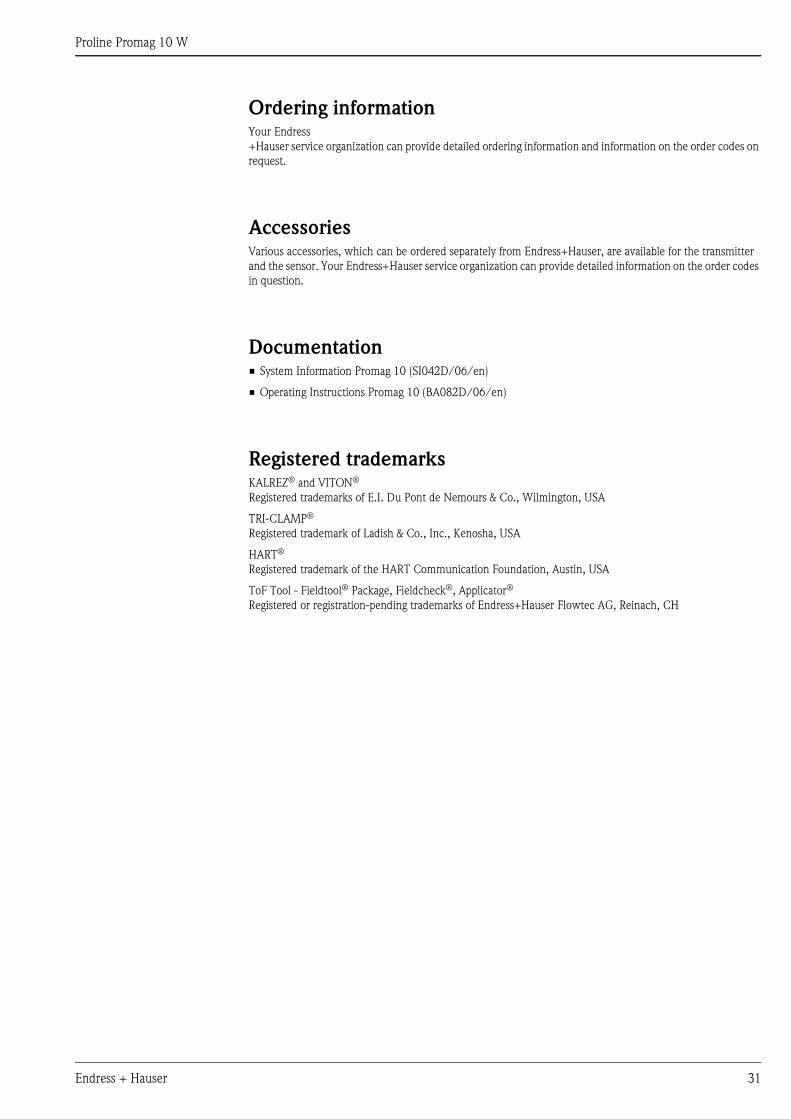
Ordering information. . . . . . . . . . . . . . . . . . . . . . . . . 31
Accessories . . . . . . . . . . . . . . . . . . . . . . . . . . . . . . . . 31
Documentation . . . . . . . . . . . . . . . . . . . . . . . . . . . . . 31
Registered trademarks . . . . . . . . . . . . . . . . . . . . . . . . 31
Proline Promag 10 W
Endress + Hauser 3
Function and system design
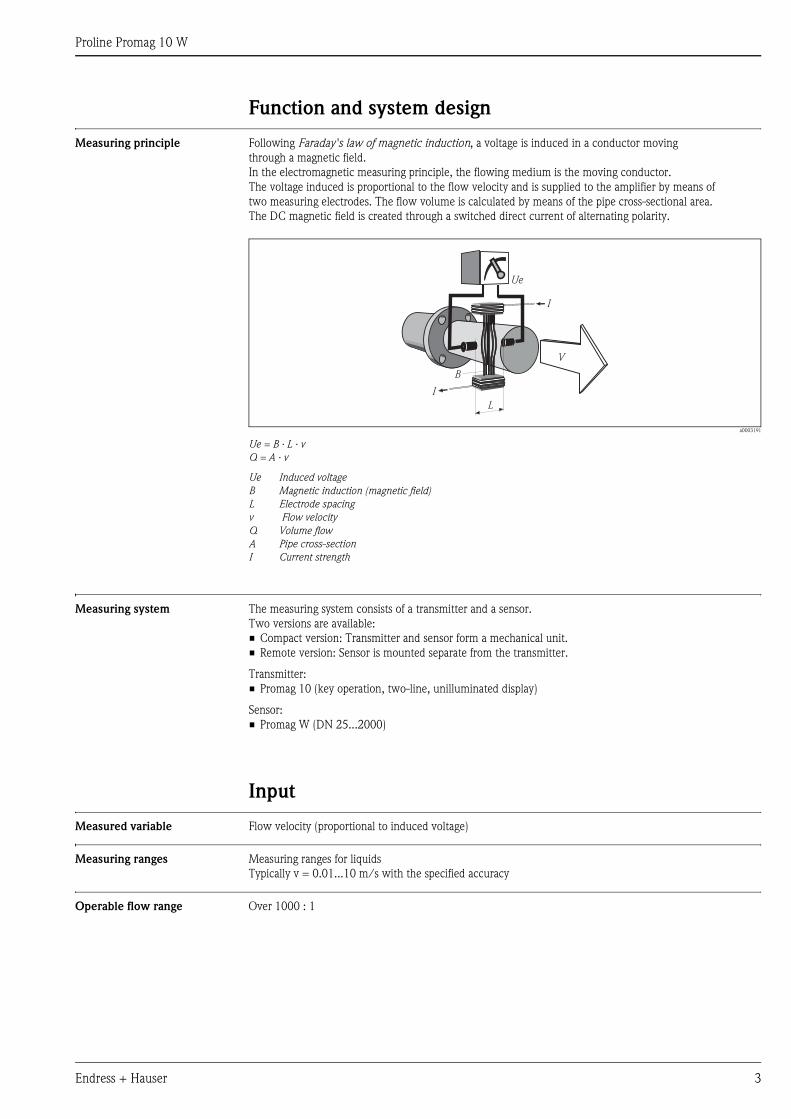
Measuring principle Following Faraday's law of magnetic induction, a voltage is induced in a conductor moving
through a magnetic field.
In the electromagnetic measuring principle, the flowing medium is the moving conductor.
The voltage induced is proportional to the flow velocity and is supplied to the amplifier by means of
two measuring electrodes. The flow volume is calculated by means of the pipe cross-sectional area.
The DC magnetic field is created through a switched direct current of alternating polarity.
a0003191
Ue = B · L · v
Q = A · v
Ue Induced voltage
B Magnetic induction (magnetic field)
L Electrode spacing
v Flow velocity
Q Volume flow
A Pipe cross-section
I Current strength
Measuring system The measuring system consists of a transmitter and a sensor.
Two versions are available:
• Compact version: Transmitter and sensor form a mechanical unit.
• Remote version: Sensor is mounted separate from the transmitter.
Transmitter:
• Promag 10 (key operation, two-line, unilluminated display)
Sensor:
• Promag W (DN 25...2000)
Input
Measured variable Flow velocity (proportional to induced voltage)
Measuring ranges Measuring ranges for liquids
Typically v = 0.01...10 m/s with the specified accuracy
Operable flow range Over 1000 : 1
Ue
I
I
B
L
V
Proline Promag 10 W
4 Endress + Hauser
Output
Output signal Current output
• Galvanically isolated
• Active: 4...20 mA, RL < 700 Ω (for HART: RL ≥ 250 Ω)
• Full scale value adjustable
• Temperature coefficient: typ. 2 μA/°C, resolution: 1.5 μA
Pulse/status output
• Galvanically isolated
• Passive: 30 V DC / 250 mA
• Open collector
• Can be configured as:
– Pulse output: Pulse value and pulse polarity can be selected, max. pulse width adjustable (5...2000 ms),
pulse frequency max. 100 Hz
– Status output: for example, can be configured for error messages, empty pipe detection, flow recognition,
limit value
Signal on alarm • Current output → Failsafe mode can be selected
• Pulse output → Failsafe mode can be selected
• Status output → “Not conductive” in the event of fault or power supply failure
Load See “output signal”
Low flow cut off Low flow cut off → Switch-on point can be selected as required.
Galvanic isolation All circuits for inputs, outputs and power supply are galvanically isolated from each other.
Power supply
Electrical connection,
measuring unit
a0003192
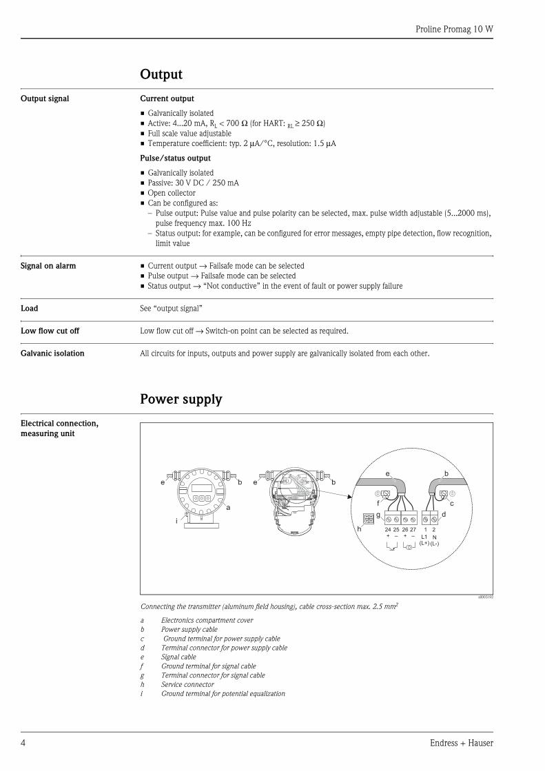
Connecting the transmitter (aluminum field housing), cable cross-section max. 2.5 mm2
a Electronics compartment cover
b Power supply cable
c Ground terminal for power supply cable
d Terminal connector for power supply cable
e Signal cable
f Ground terminal for signal cable
g Terminal connector for signal cable
h Service connector
i Ground terminal for potential equalization
b
a
e e b
2127–
25–
26+
24+ L1
(L+)N
(L-)
e
g
b
d
hi
cf
Proline Promag 10 W
Endress + Hauser 5
Electrical connection,
terminal assignment
Electrical connection, remote
version
a0003193-en
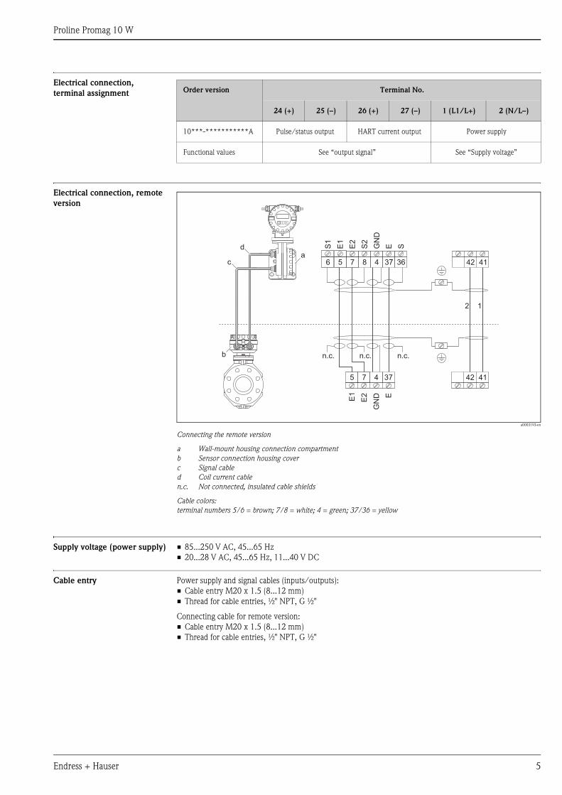
Connecting the remote version
a Wall-mount housing connection compartment
b Sensor connection housing cover
c Signal cable
d Coil current cable
n.c. Not connected, insulated cable shields
Cable colors:
terminal numbers 5/6 = brown; 7/8 = white; 4 = green; 37/36 = yellow
Supply voltage (power supply) • 85...250 V AC, 45...65 Hz
• 20...28 V AC, 45...65 Hz, 11...40 V DC
Cable entry Power supply and signal cables (inputs/outputs):
• Cable entry M20 x 1.5 (8...12 mm)
• Thread for cable entries, ½" NPT, G ½"
Connecting cable for remote version:
• Cable entry M20 x 1.5 (8...12 mm)
• Thread for cable entries, ½" NPT, G ½"
Order version Terminal No.
24 (+) 25 (–) 26 (+) 27 (–) 1 (L1/L+) 2 (N/L–)
10***-***********A Pulse/status output HART current output Power supply
Functional values See “output signal” See “Supply voltage”
E1
E2
GN
D E
a
b
S1
E1
E2
S2
GN
D
E Sd
c
5 7 4 37 42 41
42 416 5 7 8 4 37 36
2 1
n.c. n.c.n.c.
Proline Promag 10 W
6 Endress + Hauser
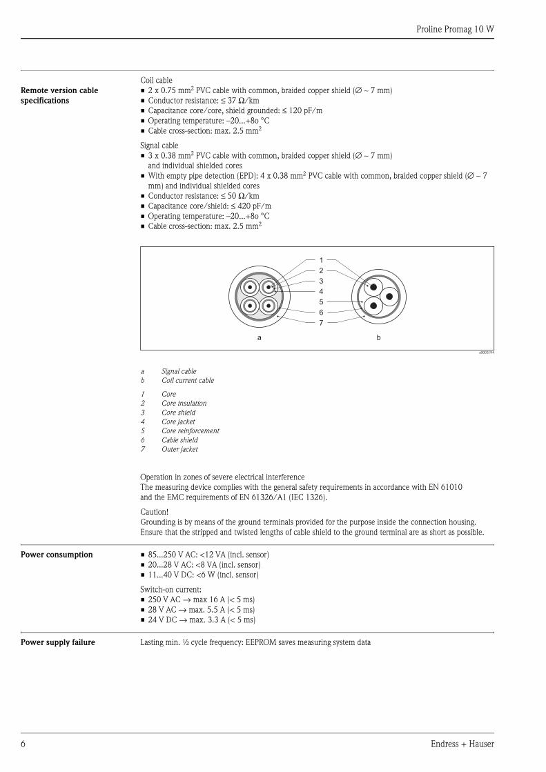
Remote version cable
specifications
Coil cable
• 2 x 0.75 mm2 PVC cable with common, braided copper shield (∅ ∼ 7 mm)
• Conductor resistance: ≤ 37 Ω/km
• Capacitance core/core, shield grounded: ≤ 120 pF/m
• Operating temperature: –20...+8o °C
• Cable cross-section: max. 2.5 mm2
Signal cable
• 3 x 0.38 mm2 PVC cable with common, braided copper shield (∅ ∼ 7 mm)
and individual shielded cores
• With empty pipe detection (EPD): 4 x 0.38 mm2 PVC cable with common, braided copper shield (∅ ∼ 7
mm) and individual shielded cores
• Conductor resistance: ≤ 50 Ω/km
• Capacitance core/shield: ≤ 420 pF/m
• Operating temperature: –20...+8o °C
• Cable cross-section: max. 2.5 mm2
a0003194
a Signal cable
b Coil current cable
1 Core
2 Core insulation
3 Core shield
4 Core jacket
5 Core reinforcement
6 Cable shield
7 Outer jacket
Operation in zones of severe electrical interference
The measuring device complies with the general safety requirements in accordance with EN 61010
and the EMC requirements of EN 61326/A1 (IEC 1326).
Caution!
Grounding is by means of the ground terminals provided for the purpose inside the connection housing.
Ensure that the stripped and twisted lengths of cable shield to the ground terminal are as short as possible.
Power consumption • 85...250 V AC: <12 VA (incl. sensor)
• 20...28 V AC: <8 VA (incl. sensor)
• 11...40 V DC: <6 W (incl. sensor)
Switch-on current:
• 250 V AC → max 16 A (< 5 ms)
• 28 V AC → max. 5.5 A (< 5 ms)
• 24 V DC → max. 3.3 A (< 5 ms)
Power supply failure Lasting min. ½ cycle frequency: EEPROM saves measuring system data
1
2
3
4
5
6
7
a b
Proline Promag 10 W
Endress + Hauser 7
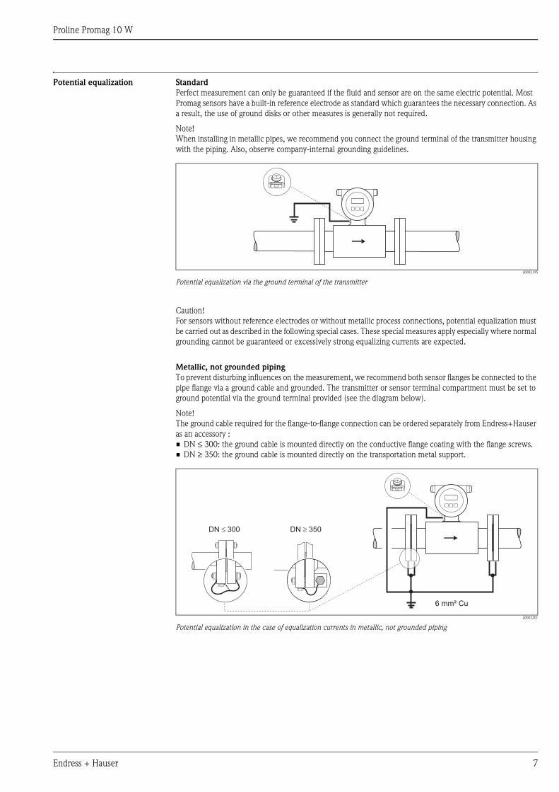
Potential equalization Standard
Perfect measurement can only be guaranteed if the fluid and sensor are on the same electric potential. Most
Promag sensors have a built-in reference electrode as standard which guarantees the necessary connection. As
a result, the use of ground disks or other measures is generally not required.
Note!
When installing in metallic pipes, we recommend you connect the ground terminal of the transmitter housing
with the piping. Also, observe company-internal grounding guidelines.
a0003195
Potential equalization via the ground terminal of the transmitter
Caution!
For sensors without reference electrodes or without metallic process connections, potential equalization must
be carried out as described in the following special cases. These special measures apply especially where normal
grounding cannot be guaranteed or excessively strong equalizing currents are expected.
Metallic, not grounded piping
To prevent disturbing influences on the measurement, we recommend both sensor flanges be connected to the
pipe flange via a ground cable and grounded. The transmitter or sensor terminal compartment must be set to
ground potential via the ground terminal provided (see the diagram below).
Note!
The ground cable required for the flange-to-flange connection can be ordered separately from Endress+Hauser
as an accessory :
• DN ≤ 300: the ground cable is mounted directly on the conductive flange coating with the flange screws.
• DN ≥ 350: the ground cable is mounted directly on the transportation metal support.
a0003201
Potential equalization in the case of equalization currents in metallic, not grounded piping
6 mm² Cu
DN 300� DN 350�
Proline Promag 10 W
8 Endress + Hauser
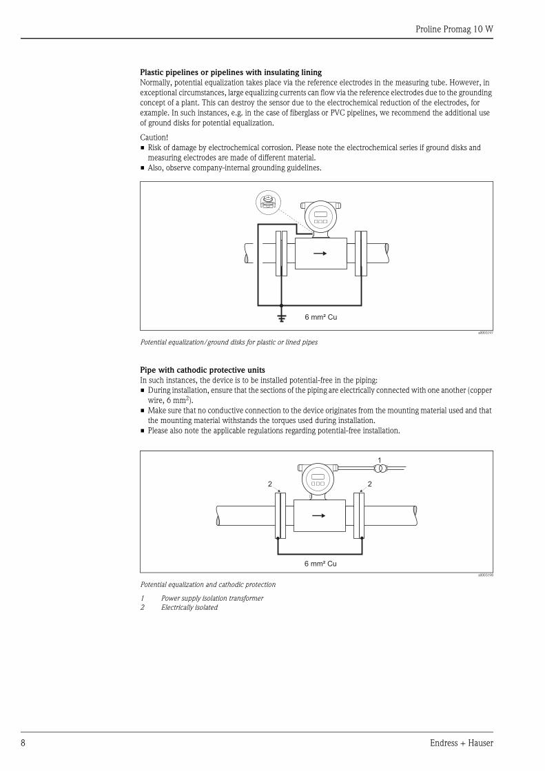
Plastic pipelines or pipelines with insulating lining
Normally, potential equalization takes place via the reference electrodes in the measuring tube. However, in
exceptional circumstances, large equalizing currents can flow via the reference electrodes due to the grounding
concept of a plant. This can destroy the sensor due to the electrochemical reduction of the electrodes, for
example. In such instances, e.g. in the case of fiberglass or PVC pipelines, we recommend the additional use
of ground disks for potential equalization.
Caution!
• Risk of damage by electrochemical corrosion. Please note the electrochemical series if ground disks and
measuring electrodes are made of different material.
• Also, observe company-internal grounding guidelines.
a0003197
Potential equalization/ground disks for plastic or lined pipes
Pipe with cathodic protective units
In such instances, the device is to be installed potential-free in the piping:
• During installation, ensure that the sections of the piping are electrically connected with one another (copper
wire, 6 mm2).
• Make sure that no conductive connection to the device originates from the mounting material used and that
the mounting material withstands the torques used during installation.
• Please also note the applicable regulations regarding potential-free installation.
a0003198
Potential equalization and cathodic protection
1 Power supply isolation transformer
2 Electrically isolated
6 mm² Cu
6 mm² Cu
2
1
2
Proline Promag 10 W
Endress + Hauser 9
Performance characteristics
Reference operating
conditions
As per DIN EN 29104 and VDI/VDE 2641:
• Fluid temperature: +28 °C ±2 K
• Ambient temperature: +22 °C ±2 K
• Warm-up period: 30 minutes
Installation:
• Inlet run >10 x DN
• Outlet run > 5 x DN
• Sensor and transmitter grounded.
• The sensor is centered in the pipe.
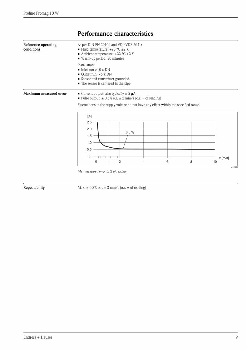
Maximum measured error • Current output: also typically ± 5 μA
• Pulse output: ± 0.5% o.r. ± 2 mm/s (o.r. = of reading)
Fluctuations in the supply voltage do not have any effect within the specified range.
a0003200
Max. measured error in % of reading
Repeatability Max. ± 0.2% o.r. ± 2 mm/s (o.r. = of reading)
0 1
2.5
[%]
2.0
1.5
1.0
0.5
0
2 4 6 8 10v [m/s]
0.5 %
Proline Promag 10 W
10 Endress + Hauser
Operating conditions: Installations
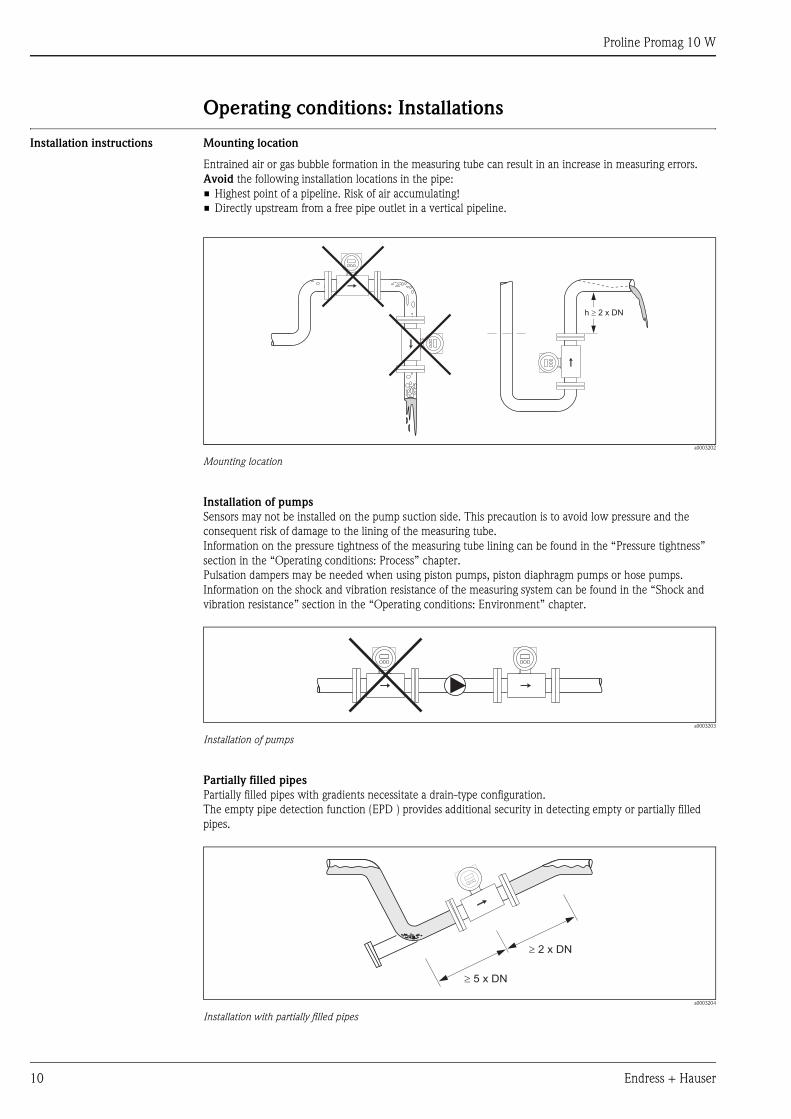
Installation instructions Mounting location
Entrained air or gas bubble formation in the measuring tube can result in an increase in measuring errors.
Avoid the following installation locations in the pipe:
• Highest point of a pipeline. Risk of air accumulating!
• Directly upstream from a free pipe outlet in a vertical pipeline.
a0003202
Mounting location
Installation of pumps
Sensors may not be installed on the pump suction side. This precaution is to avoid low pressure and the
consequent risk of damage to the lining of the measuring tube.
Information on the pressure tightness of the measuring tube lining can be found in the “Pressure tightness”
section in the “Operating conditions: Process” chapter.
Pulsation dampers may be needed when using piston pumps, piston diaphragm pumps or hose pumps.
Information on the shock and vibration resistance of the measuring system can be found in the “Shock and
vibration resistance” section in the “Operating conditions: Environment” chapter.
a0003203
Installation of pumps
Partially filled pipes
Partially filled pipes with gradients necessitate a drain-type configuration.
The empty pipe detection function (EPD ) provides additional security in detecting empty or partially filled
pipes.
a0003204
Installation with partially filled pipes
h 2 x DN³
³ 5 x DN
³ 2 x DN
Proline Promag 10 W
Endress + Hauser 11
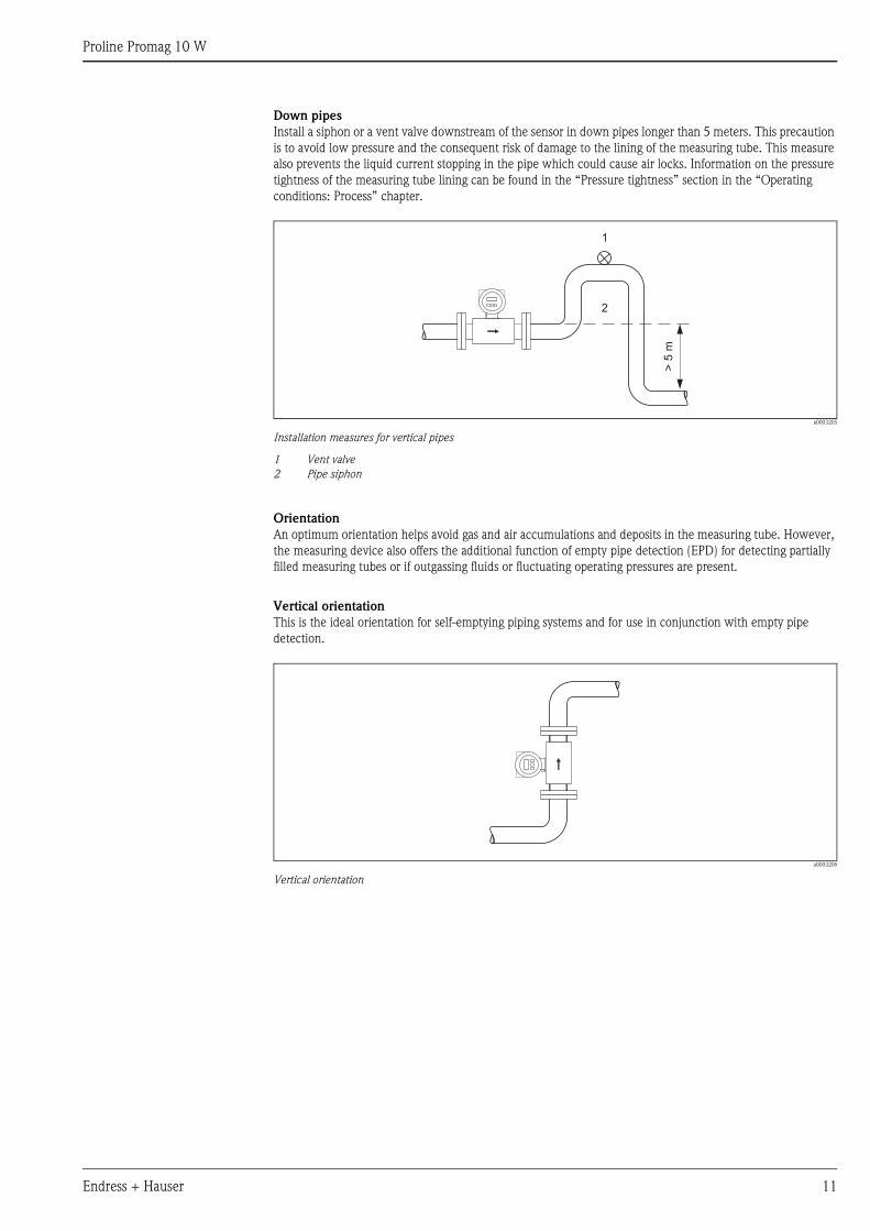
Down pipes
Install a siphon or a vent valve downstream of the sensor in down pipes longer than 5 meters. This precaution
is to avoid low pressure and the consequent risk of damage to the lining of the measuring tube. This measure
also prevents the liquid current stopping in the pipe which could cause air locks. Information on the pressure
tightness of the measuring tube lining can be found in the “Pressure tightness” section in the “Operating
conditions: Process” chapter.
a0003205
Installation measures for vertical pipes
1 Vent valve
2 Pipe siphon
Orientation
An optimum orientation helps avoid gas and air accumulations and deposits in the measuring tube. However,
the measuring device also offers the additional function of empty pipe detection (EPD) for detecting partially
filled measuring tubes or if outgassing fluids or fluctuating operating pressures are present.
Vertical orientation
This is the ideal orientation for self-emptying piping systems and for use in conjunction with empty pipe
detection.
a0003206
Vertical orientation
>5
m
2
1
Proline Promag 10 W
12 Endress + Hauser
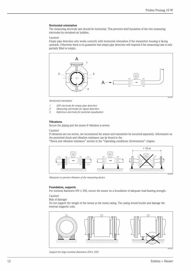
Horizontal orientation
The measuring electrode axis should be horizontal. This prevents brief insulation of the two measuring
electrodes by entrained air bubbles.
Caution!
Empty pipe detection only works correctly with horizontal orientation if the transmitter housing is facing
upwards. Otherwise there is no guarantee that empty pipe detection will respond if the measuring tube is only
partially filled or empty.
a0003207
Horizontal orientation
1 EPD electrode for empty pipe detection
2 Measuring electrodes for signal detection
3 Reference electrode for potential equalization
Vibrations
Secure the piping and the sensor if vibration is severe.
Caution!
If vibrations are too severe, we recommend the sensor and transmitter be mounted separately. Information on
the permitted shock and vibration resistance can be found in the
“Shock and vibration resistance” section in the “Operating conditions: Environment” chapter.
a0003208
Measures to prevent vibration of the measuring device
Foundation, supports
For nominal diameters DN ≥ 350, mount the sensor on a foundation of adequate load-bearing strength.
Caution!
Risk of damage!
Do not support the weight of the sensor at the metal casing. The casing would buckle and damage the
internal magnetic coils.
a0003209
Support for large nominal diameters (DN ≥ 350)
A1
2 2
A
3
> 10 m
Proline Promag 10 W
Endress + Hauser 13
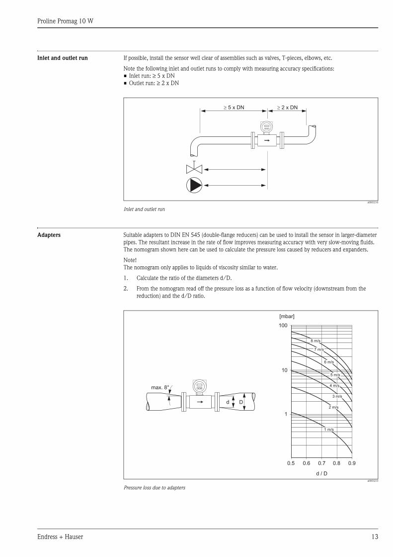
Inlet and outlet run If possible, install the sensor well clear of assemblies such as valves, T-pieces, elbows, etc.
Note the following inlet and outlet runs to comply with measuring accuracy specifications:
• Inlet run: ≥ 5 x DN
• Outlet run: ≥ 2 x DN
a0003210
Inlet and outlet run
Adapters Suitable adapters to DIN EN 545 (double-flange reducers) can be used to install the sensor in larger-diameter
pipes. The resultant increase in the rate of flow improves measuring accuracy with very slow-moving fluids.
The nomogram shown here can be used to calculate the pressure loss caused by reducers and expanders.
Note!
The nomogram only applies to liquids of viscosity similar to water.
1. Calculate the ratio of the diameters d/D.
2. From the nomogram read off the pressure loss as a function of flow velocity (downstream from the
reduction) and the d/D ratio.
a0003213
Pressure loss due to adapters
5 x DN� � 2 x DN
100
10
0.5
d / D
[mbar]
0.6 0.7 0.8 0.9
1 m/s
2 m/s
3 m/s
4 m/s
5 m/s
6 m/s
7 m/s
8 m/s
1
Dd
max. 8°
Proline Promag 10 W
14 Endress + Hauser
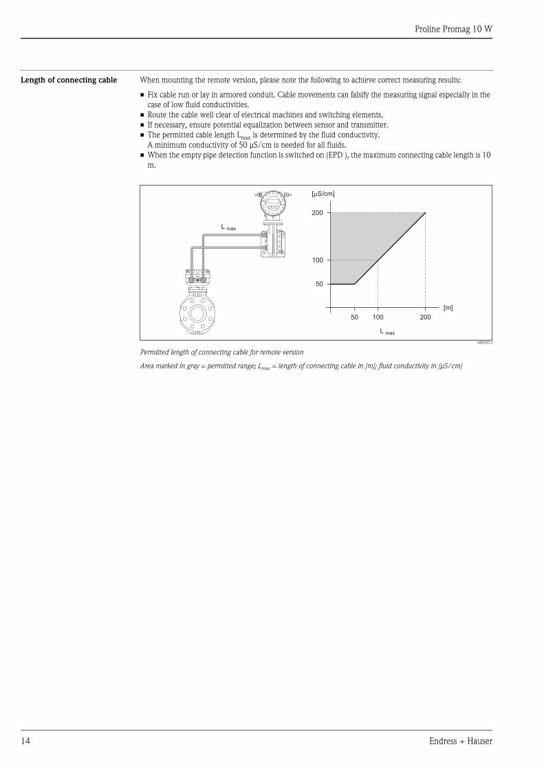
Length of connecting cable When mounting the remote version, please note the following to achieve correct measuring results:
• Fix cable run or lay in armored conduit. Cable movements can falsify the measuring signal especially in the
case of low fluid conductivities.
• Route the cable well clear of electrical machines and switching elements.
• If necessary, ensure potential equalization between sensor and transmitter.
• The permitted cable length Lmax is determined by the fluid conductivity.
A minimum conductivity of 50 μS/cm is needed for all fluids.
• When the empty pipe detection function is switched on (EPD ), the maximum connecting cable length is 10
m.
a0003214
Permitted length of connecting cable for remote version
Area marked in gray = permitted range; Lmax = length of connecting cable in [m]; fluid conductivity in [μS/cm]
200
100
50 100 200
[m]
[ S/cm]m
L max
L max
50
Proline Promag 10 W
Endress + Hauser 15
Operating conditions: Environment
Ambient temperature range • Sensor: -20...+60 °C
• Transmitter: -10...+60 °C
Caution!
The permitted temperature range of the measuring tube lining may not be undershot or overshot
(→ “Operating conditions: Process” → “Medium temperature range”).
Please note the following points:
• Install the device in a shady location. Avoid direct sunlight, particularly in warm climatic regions.
• The transmitter must be mounted separate from the sensor if both the ambient and fluid temperatures are
high.
Storage temperature • The temperature range for storing the device corresponds to the permitted ambient
temperature range of the transmitter and the sensor (see “Ambient temperature range”).
• The measuring device must be protected against direct sunlight during storage in order to avoid unacceptably
high surface temperatures.
• A storage location must be selected where moisture does not collect in the measuring device. This will help
prevent fungus and bacteria infestation which can damage the liner.
• If protecting caps or protective covers are mounted, these must not be removed before mounting the device.
Degree of protection • Standard: IP 67 (NEMA 4X) for transmitter and sensor
• Optional: IP 68 (NEMA 6P) for sensor for remote version
Shock and vibration resistance Acceleration up to 2 g following IEC 600 68-2-6
Electromagnetic compatibility
(EMC)
• As per EN 61326
• Emission: to limit value for industry EN 55011
Proline Promag 10 W
16 Endress + Hauser
Operating conditions: Process
Medium temperature range The permitted temperature depends on the measuring tube lining:
• 0...+80 °C for hard rubber (DN 65...2000)
• –20...+50 °C for polyurethane (DN 25...1000)
Conductivity The minimum conductivity is: ≥ 50 μS/cm
Note!
In the remote version, the necessary minimum conductivity also depends on the cable length
(→ “Operating conditions: Installation” → “Length of connecting cable”).
Medium pressure range
(nominal pressure)
• EN 1092-1 (DIN 2501)
– PN 6 (DN 1200...2000)
– PN 10 (DN 200...2000)
– PN 16 (DN 65...2000)
– PN 25 (DN 200...1000)
– PN 40 (DN 25...150)
• ANSI B 16.5
– Class 150 (DN 1"...24")
– Class 300 (DN 1"...6")
• AWWA
– Class D (DN 28"...78")
• JIS B2238
– 10 K (DN 50...300)
– 20 K (DN 25...300)
• AS 2129
– Table E (DN 80, 100, 150...400, 500, 600)
• AS 4087
– Cl. 14 (DN 80, 100, 150...400, 500, 600)
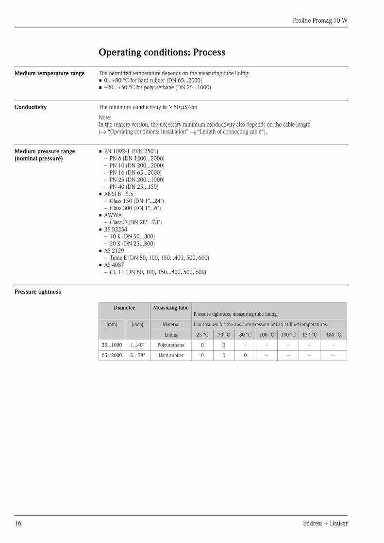
Pressure tightness
Diameter Measuring tube
Pressure tightness, measuring tube lining
[mm] [inch] Material Limit values for the absolute pressure [mbar] at fluid temperatures:
Lining 25 °C 70 °C 80 °C 100 °C 130 °C 150 °C 180 °C
25...1000 1...40" Polyurethane 0 0 - - - - -
65...2000 3…78" Hard rubber 0 0 0 - - - -
Proline Promag 10 W
Endress + Hauser 17
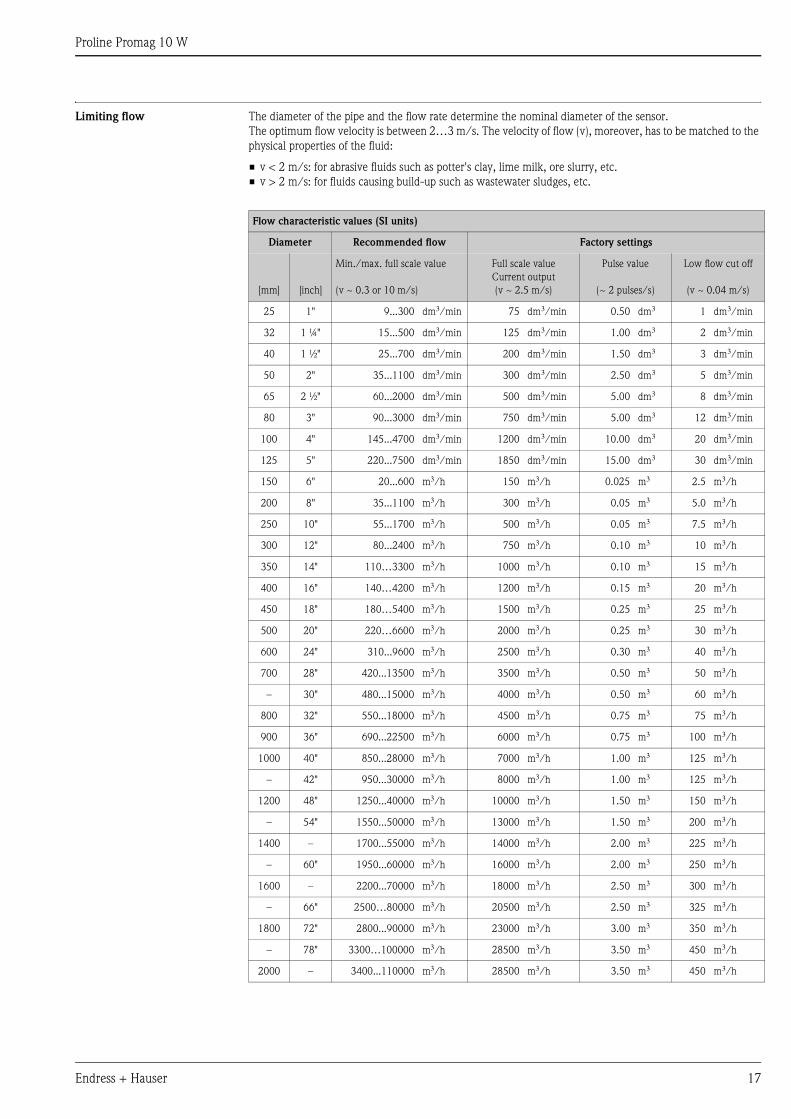
Limiting flow The diameter of the pipe and the flow rate determine the nominal diameter of the sensor.
The optimum flow velocity is between 2…3 m/s. The velocity of flow (v), moreover, has to be matched to the
physical properties of the fluid:
• v < 2 m/s: for abrasive fluids such as potter's clay, lime milk, ore slurry, etc.
• v > 2 m/s: for fluids causing build-up such as wastewater sludges, etc.
Flow characteristic values (SI units)
Diameter Recommended flow Factory settings
[mm] [inch]
Min./max. full scale value
(v ~ 0.3 or 10 m/s)
Full scale value
Current output
(v ~ 2.5 m/s)
Pulse value
(~ 2 pulses/s)
Low flow cut off
(v ~ 0.04 m/s)
25 1" 9...300 dm3/min 75 dm3/min 0.50 dm3 1 dm3/min
32 1 ¼" 15...500 dm3/min 125 dm3/min 1.00 dm3 2 dm3/min
40 1 ½" 25...700 dm3/min 200 dm3/min 1.50 dm3 3 dm3/min
50 2" 35...1100 dm3/min 300 dm3/min 2.50 dm3 5 dm3/min
65 2 ½" 60...2000 dm3/min 500 dm3/min 5.00 dm3 8 dm3/min
80 3" 90...3000 dm3/min 750 dm3/min 5.00 dm3 12 dm3/min
100 4" 145...4700 dm3/min 1200 dm3/min 10.00 dm3 20 dm3/min
125 5" 220...7500 dm3/min 1850 dm3/min 15.00 dm3 30 dm3/min
150 6" 20...600 m3/h 150 m3/h 0.025 m3 2.5 m3/h
200 8" 35...1100 m3/h 300 m3/h 0.05 m3 5.0 m3/h
250 10" 55...1700 m3/h 500 m3/h 0.05 m3 7.5 m3/h
300 12" 80...2400 m3/h 750 m3/h 0.10 m3 10 m3/h
350 14" 110…3300 m3/h 1000 m3/h 0.10 m3 15 m3/h
400 16" 140…4200 m3/h 1200 m3/h 0.15 m3 20 m3/h
450 18" 180…5400 m3/h 1500 m3/h 0.25 m3 25 m3/h
500 20" 220…6600 m3/h 2000 m3/h 0.25 m3 30 m3/h
600 24" 310...9600 m3/h 2500 m3/h 0.30 m3 40 m3/h
700 28" 420...13500 m3/h 3500 m3/h 0.50 m3 50 m3/h
– 30" 480...15000 m3/h 4000 m3/h 0.50 m3 60 m3/h
800 32" 550...18000 m3/h 4500 m3/h 0.75 m3 75 m3/h
900 36" 690...22500 m3/h 6000 m3/h 0.75 m3 100 m3/h
1000 40" 850...28000 m3/h 7000 m3/h 1.00 m3 125 m3/h
– 42" 950...30000 m3/h 8000 m3/h 1.00 m3 125 m3/h
1200 48" 1250...40000 m3/h 10000 m3/h 1.50 m3 150 m3/h
– 54" 1550...50000 m3/h 13000 m3/h 1.50 m3 200 m3/h
1400 – 1700...55000 m3/h 14000 m3/h 2.00 m3 225 m3/h
– 60" 1950...60000 m3/h 16000 m3/h 2.00 m3 250 m3/h
1600 – 2200...70000 m3/h 18000 m3/h 2.50 m3 300 m3/h
– 66" 2500…80000 m3/h 20500 m3/h 2.50 m3 325 m3/h
1800 72" 2800...90000 m3/h 23000 m3/h 3.00 m3 350 m3/h
– 78" 3300…100000 m3/h 28500 m3/h 3.50 m3 450 m3/h
2000 – 3400...110000 m3/h 28500 m3/h 3.50 m3 450 m3/h
Proline Promag 10 W
18 Endress + Hauser
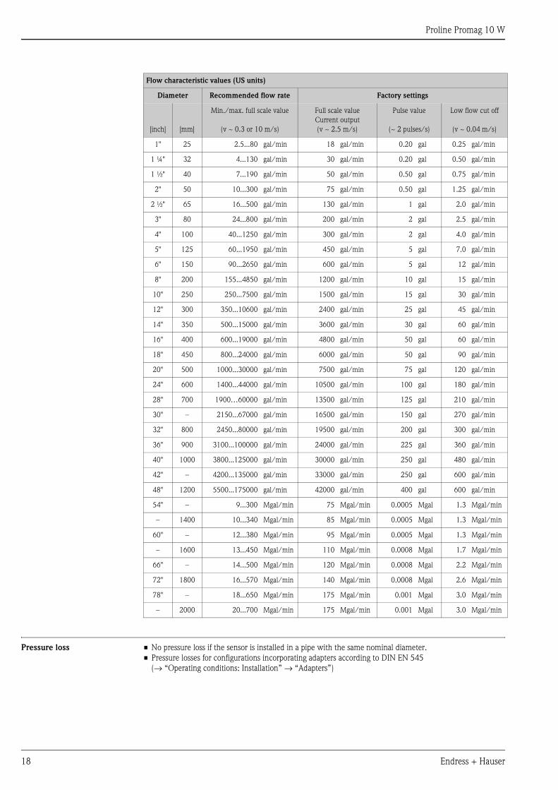
Pressure loss • No pressure loss if the sensor is installed in a pipe with the same nominal diameter.
• Pressure losses for configurations incorporating adapters according to DIN EN 545
(→ “Operating conditions: Installation” → “Adapters”)
Flow characteristic values (US units)
Diameter Recommended flow rate Factory settings
[inch] [mm]
Min./max. full scale value
(v ~ 0.3 or 10 m/s)
Full scale value
Current output
(v ~ 2.5 m/s)
Pulse value
(~ 2 pulses/s)
Low flow cut off
(v ~ 0.04 m/s)
1" 25 2.5...80 gal/min 18 gal/min 0.20 gal 0.25 gal/min
1 ¼" 32 4...130 gal/min 30 gal/min 0.20 gal 0.50 gal/min
1 ½" 40 7...190 gal/min 50 gal/min 0.50 gal 0.75 gal/min
2" 50 10...300 gal/min 75 gal/min 0.50 gal 1.25 gal/min
2 ½" 65 16...500 gal/min 130 gal/min 1 gal 2.0 gal/min
3" 80 24...800 gal/min 200 gal/min 2 gal 2.5 gal/min
4" 100 40...1250 gal/min 300 gal/min 2 gal 4.0 gal/min
5" 125 60...1950 gal/min 450 gal/min 5 gal 7.0 gal/min
6" 150 90...2650 gal/min 600 gal/min 5 gal 12 gal/min
8" 200 155...4850 gal/min 1200 gal/min 10 gal 15 gal/min
10" 250 250...7500 gal/min 1500 gal/min 15 gal 30 gal/min
12" 300 350...10600 gal/min 2400 gal/min 25 gal 45 gal/min
14" 350 500...15000 gal/min 3600 gal/min 30 gal 60 gal/min
16" 400 600...19000 gal/min 4800 gal/min 50 gal 60 gal/min
18" 450 800...24000 gal/min 6000 gal/min 50 gal 90 gal/min
20" 500 1000...30000 gal/min 7500 gal/min 75 gal 120 gal/min
24" 600 1400...44000 gal/min 10500 gal/min 100 gal 180 gal/min
28" 700 1900…60000 gal/min 13500 gal/min 125 gal 210 gal/min
30" – 2150...67000 gal/min 16500 gal/min 150 gal 270 gal/min
32" 800 2450...80000 gal/min 19500 gal/min 200 gal 300 gal/min
36" 900 3100...100000 gal/min 24000 gal/min 225 gal 360 gal/min
40" 1000 3800...125000 gal/min 30000 gal/min 250 gal 480 gal/min
42" – 4200...135000 gal/min 33000 gal/min 250 gal 600 gal/min
48" 1200 5500...175000 gal/min 42000 gal/min 400 gal 600 gal/min
54" – 9...300 Mgal/min 75 Mgal/min 0.0005 Mgal 1.3 Mgal/min
– 1400 10...340 Mgal/min 85 Mgal/min 0.0005 Mgal 1.3 Mgal/min
60" – 12...380 Mgal/min 95 Mgal/min 0.0005 Mgal 1.3 Mgal/min
– 1600 13...450 Mgal/min 110 Mgal/min 0.0008 Mgal 1.7 Mgal/min
66" – 14...500 Mgal/min 120 Mgal/min 0.0008 Mgal 2.2 Mgal/min
72" 1800 16...570 Mgal/min 140 Mgal/min 0.0008 Mgal 2.6 Mgal/min
78" – 18...650 Mgal/min 175 Mgal/min 0.001 Mgal 3.0 Mgal/min
– 2000 20...700 Mgal/min 175 Mgal/min 0.001 Mgal 3.0 Mgal/min
Proline Promag 10 W
Endress + Hauser 19
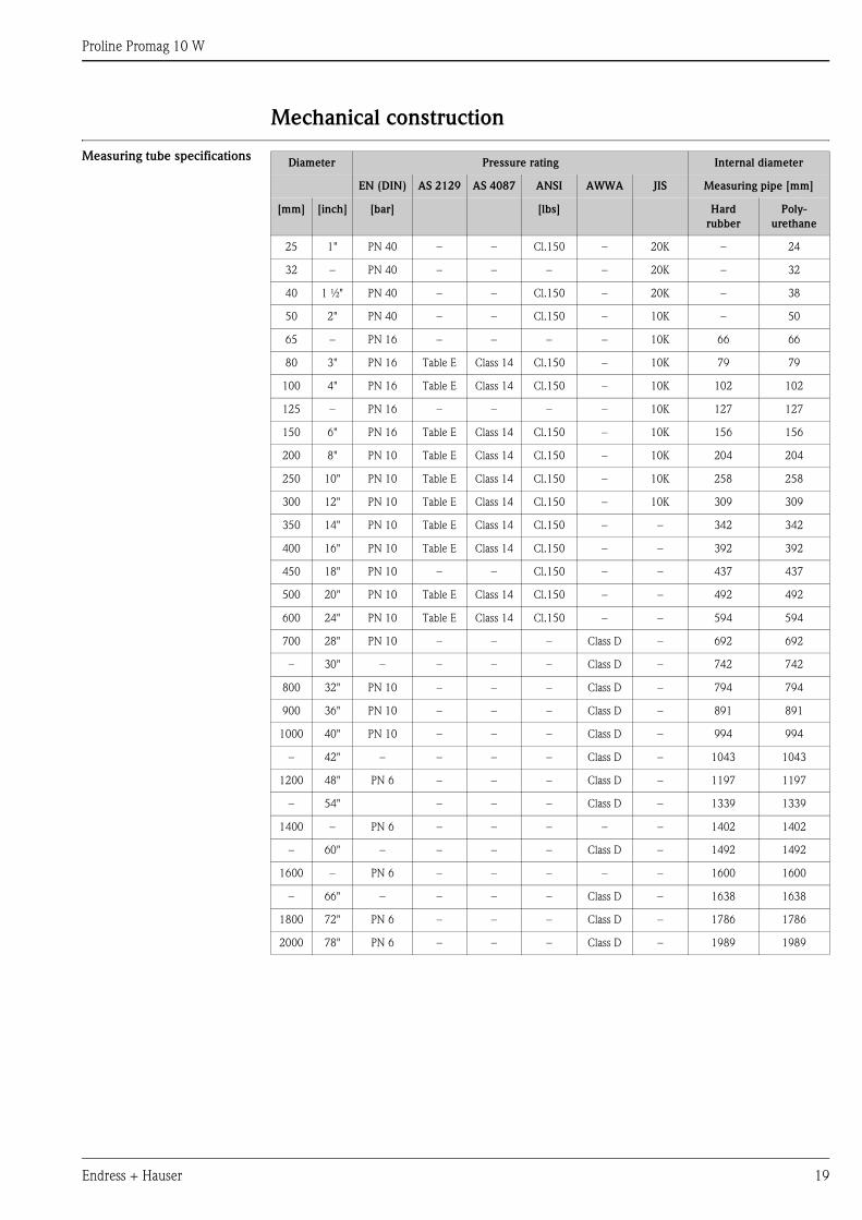
Mechanical construction
Measuring tube specificationsDiameter Pressure rating Internal diameter
EN (DIN) AS 2129 AS 4087 ANSI AWWA JIS Measuring pipe [mm]
[mm] [inch] [bar] [lbs] Hard
rubber
Poly-
urethane
25 1" PN 40 – – Cl.150 – 20K – 24
32 – PN 40 – – – – 20K – 32
40 1 ½" PN 40 – – Cl.150 – 20K – 38
50 2" PN 40 – – Cl.150 – 10K – 50
65 – PN 16 – – – – 10K 66 66
80 3" PN 16 Table E Class 14 Cl.150 – 10K 79 79
100 4" PN 16 Table E Class 14 Cl.150 – 10K 102 102
125 – PN 16 – – – – 10K 127 127
150 6" PN 16 Table E Class 14 Cl.150 – 10K 156 156
200 8" PN 10 Table E Class 14 Cl.150 – 10K 204 204
250 10" PN 10 Table E Class 14 Cl.150 – 10K 258 258
300 12" PN 10 Table E Class 14 Cl.150 – 10K 309 309
350 14" PN 10 Table E Class 14 Cl.150 – – 342 342
400 16" PN 10 Table E Class 14 Cl.150 – – 392 392
450 18" PN 10 – – Cl.150 – – 437 437
500 20" PN 10 Table E Class 14 Cl.150 – – 492 492
600 24" PN 10 Table E Class 14 Cl.150 – – 594 594
700 28" PN 10 – – – Class D – 692 692
– 30" – – – – Class D – 742 742
800 32" PN 10 – – – Class D – 794 794
900 36" PN 10 – – – Class D – 891 891
1000 40" PN 10 – – – Class D – 994 994
– 42" – – – – Class D – 1043 1043
1200 48" PN 6 – – – Class D – 1197 1197
– 54" – – – Class D – 1339 1339
1400 – PN 6 – – – – – 1402 1402
– 60" – – – – Class D – 1492 1492
1600 – PN 6 – – – – – 1600 1600
– 66" – – – – Class D – 1638 1638
1800 72" PN 6 – – – Class D – 1786 1786
2000 78" PN 6 – – – Class D – 1989 1989
Proline Promag 10 W
20 Endress + Hauser
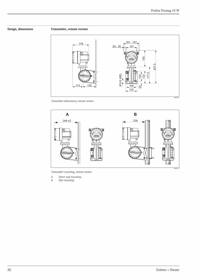
Design, dimensions Transmitter, remote version
a0003215
Transmitter dimensions, remote version
a0003216
Transmitter mounting, remote version
A Direct wall mounting
B Pipe mounting
150
178
Esc
E- +
12120...30
161...181
ANSCHLUSSKLEMMEN - FIELD TERMINALS
10
02
5Ø8.6
(M8)
133
177.5
100
123
135113
327
5.ANSCHLUSSKLEMMEN - FIELD TERMINALS
248 ±2
Esc
E- +
A
238
ANSCHLUSSKLEMMEN - FIELD TERMINALS
Esc
E- +
B
Proline Promag 10 W
Endress + Hauser 21
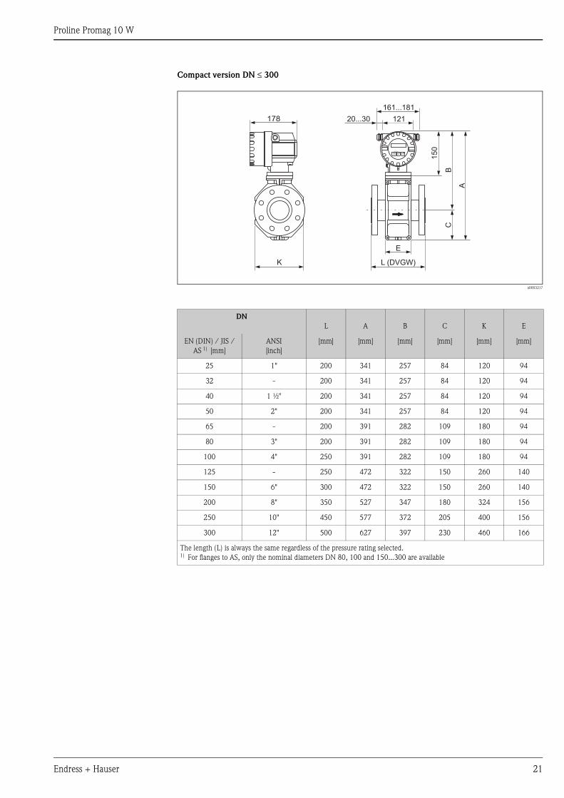
Compact version DN ≤ 300
a0003217
DN
L A B C K E
EN (DIN) / JIS /
AS 1) [mm]
ANSI
[inch]
[mm] [mm] [mm] [mm] [mm] [mm]
25 1" 200 341 257 84 120 94
32 - 200 341 257 84 120 94
40 1 ½" 200 341 257 84 120 94
50 2" 200 341 257 84 120 94
65 - 200 391 282 109 180 94
80 3" 200 391 282 109 180 94
100 4" 250 391 282 109 180 94
125 - 250 472 322 150 260 140
150 6" 300 472 322 150 260 140
200 8" 350 527 347 180 324 156
250 10" 450 577 372 205 400 156
300 12" 500 627 397 230 460 166
The length (L) is always the same regardless of the pressure rating selected.1) For flanges to AS, only the nominal diameters DN 80, 100 and 150...300 are available
K
E
L (DVGW)
15
0
A
CB
178
Esc
E- +
12120...30
161...181
Proline Promag 10 W
22 Endress + Hauser
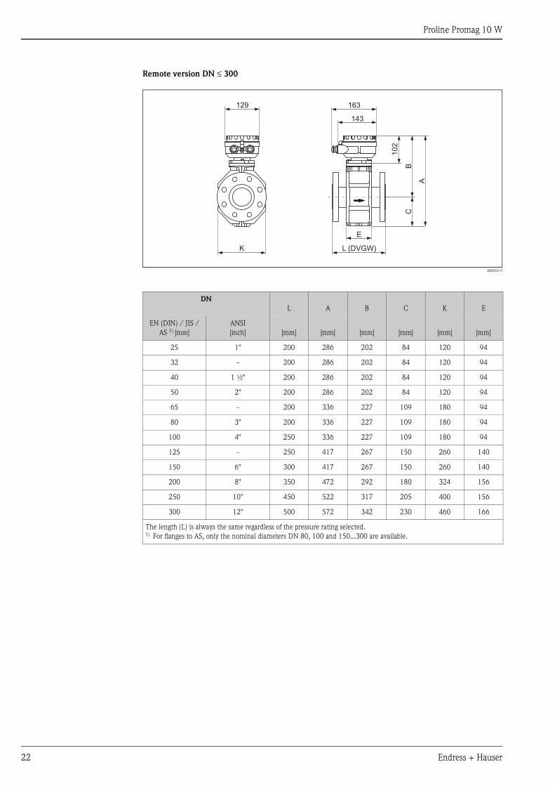
Remote version DN ≤ 300
a0003219
DN
L A B C K E
EN (DIN) / JIS /
AS 1) [mm]
ANSI
[inch] [mm] [mm] [mm] [mm] [mm] [mm]
25 1" 200 286 202 84 120 94
32 - 200 286 202 84 120 94
40 1 ½" 200 286 202 84 120 94
50 2" 200 286 202 84 120 94
65 - 200 336 227 109 180 94
80 3" 200 336 227 109 180 94
100 4" 250 336 227 109 180 94
125 - 250 417 267 150 260 140
150 6" 300 417 267 150 260 140
200 8" 350 472 292 180 324 156
250 10" 450 522 317 205 400 156
300 12" 500 572 342 230 460 166
The length (L) is always the same regardless of the pressure rating selected.1) For flanges to AS, only the nominal diameters DN 80, 100 and 150...300 are available.
E
L (DVGW)
163
143
102
A
CB
129
K
Proline Promag 10 W
Endress + Hauser 23
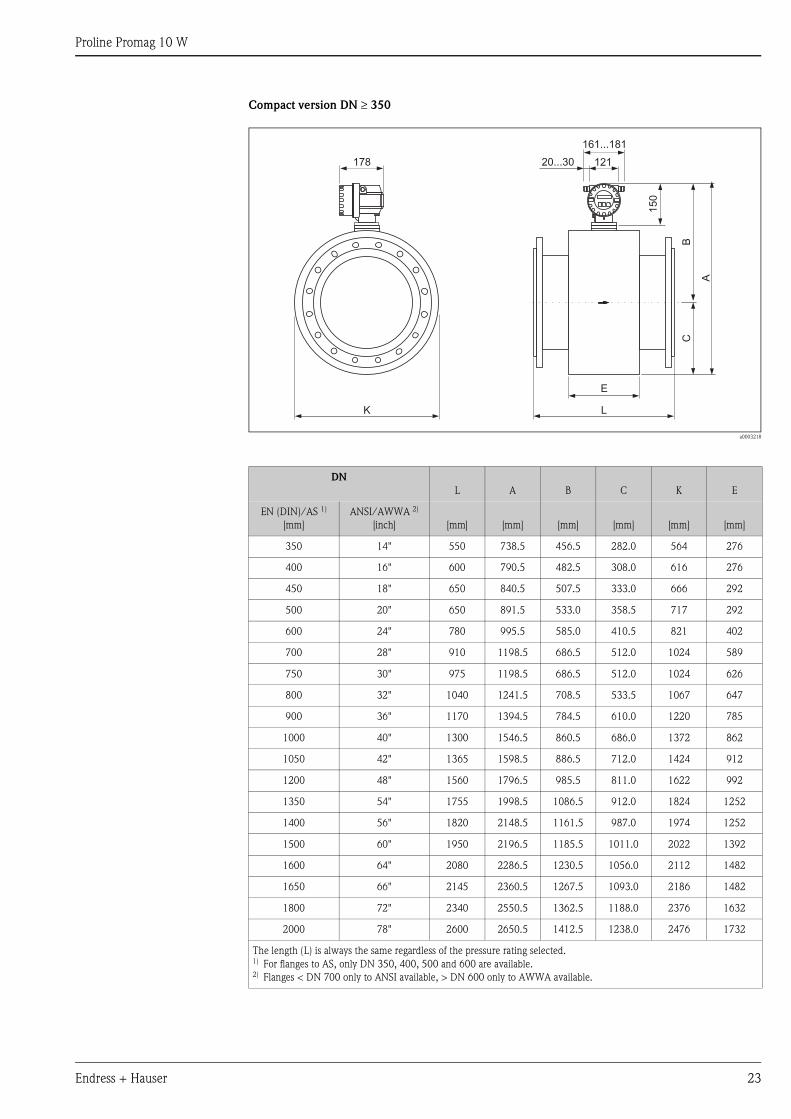
Compact version DN ≥ 350
a0003218
DN
L A B C K E
EN (DIN)/AS 1)
[mm]
ANSI/AWWA 2)
[inch] [mm] [mm] [mm] [mm] [mm] [mm]
350 14" 550 738.5 456.5 282.0 564 276
400 16" 600 790.5 482.5 308.0 616 276
450 18" 650 840.5 507.5 333.0 666 292
500 20" 650 891.5 533.0 358.5 717 292
600 24" 780 995.5 585.0 410.5 821 402
700 28" 910 1198.5 686.5 512.0 1024 589
750 30" 975 1198.5 686.5 512.0 1024 626
800 32" 1040 1241.5 708.5 533.5 1067 647
900 36" 1170 1394.5 784.5 610.0 1220 785
1000 40" 1300 1546.5 860.5 686.0 1372 862
1050 42" 1365 1598.5 886.5 712.0 1424 912
1200 48" 1560 1796.5 985.5 811.0 1622 992
1350 54" 1755 1998.5 1086.5 912.0 1824 1252
1400 56" 1820 2148.5 1161.5 987.0 1974 1252
1500 60" 1950 2196.5 1185.5 1011.0 2022 1392
1600 64" 2080 2286.5 1230.5 1056.0 2112 1482
1650 66" 2145 2360.5 1267.5 1093.0 2186 1482
1800 72" 2340 2550.5 1362.5 1188.0 2376 1632
2000 78" 2600 2650.5 1412.5 1238.0 2476 1732
The length (L) is always the same regardless of the pressure rating selected.1) For flanges to AS, only DN 350, 400, 500 and 600 are available.2) Flanges < DN 700 only to ANSI available, > DN 600 only to AWWA available.
A
CB
L
E
K
150
178 12120...30
161...181
Esc
E- +
Proline Promag 10 W
24 Endress + Hauser
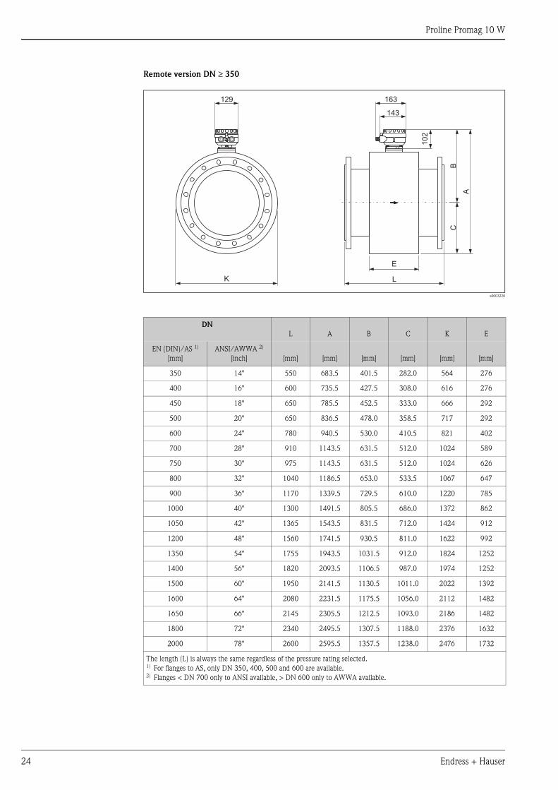
Remote version DN ≥ 350
a0003220
DN
L A B C K E
EN (DIN)/AS 1)
[mm]
ANSI/AWWA 2)
[inch] [mm] [mm] [mm] [mm] [mm] [mm]
350 14" 550 683.5 401.5 282.0 564 276
400 16" 600 735.5 427.5 308.0 616 276
450 18" 650 785.5 452.5 333.0 666 292
500 20" 650 836.5 478.0 358.5 717 292
600 24" 780 940.5 530.0 410.5 821 402
700 28" 910 1143.5 631.5 512.0 1024 589
750 30" 975 1143.5 631.5 512.0 1024 626
800 32" 1040 1186.5 653.0 533.5 1067 647
900 36" 1170 1339.5 729.5 610.0 1220 785
1000 40" 1300 1491.5 805.5 686.0 1372 862
1050 42" 1365 1543.5 831.5 712.0 1424 912
1200 48" 1560 1741.5 930.5 811.0 1622 992
1350 54" 1755 1943.5 1031.5 912.0 1824 1252
1400 56" 1820 2093.5 1106.5 987.0 1974 1252
1500 60" 1950 2141.5 1130.5 1011.0 2022 1392
1600 64" 2080 2231.5 1175.5 1056.0 2112 1482
1650 66" 2145 2305.5 1212.5 1093.0 2186 1482
1800 72" 2340 2495.5 1307.5 1188.0 2376 1632
2000 78" 2600 2595.5 1357.5 1238.0 2476 1732
The length (L) is always the same regardless of the pressure rating selected.1) For flanges to AS, only DN 350, 400, 500 and 600 are available.2) Flanges < DN 700 only to ANSI available, > DN 600 only to AWWA available.
129
K
A
CB
102
163
143
L
E
Proline Promag 10 W
Endress + Hauser 25
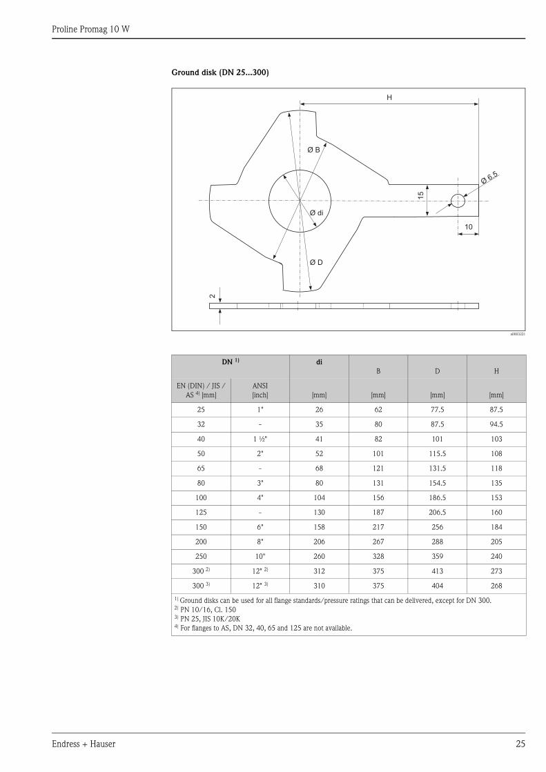
Ground disk (DN 25...300)
a0003221
DN 1) di
B D H
EN (DIN) / JIS /
AS 4) [mm]
ANSI
[inch] [mm] [mm] [mm] [mm]
25 1" 26 62 77.5 87.5
32 - 35 80 87.5 94.5
40 1 ½" 41 82 101 103
50 2" 52 101 115.5 108
65 - 68 121 131.5 118
80 3" 80 131 154.5 135
100 4" 104 156 186.5 153
125 - 130 187 206.5 160
150 6" 158 217 256 184
200 8" 206 267 288 205
250 10" 260 328 359 240
300 2) 12" 2) 312 375 413 273
300 3) 12" 3) 310 375 404 268
1) Ground disks can be used for all flange standards/pressure ratings that can be delivered, except for DN 300.2) PN 10/16, Cl. 1503) PN 25, JIS 10K/20K4) For flanges to AS, DN 32, 40, 65 and 125 are not available.
15
10
H
Ø B
Ø di
Ø D
Ø6.5
2
Proline Promag 10 W
26 Endress + Hauser
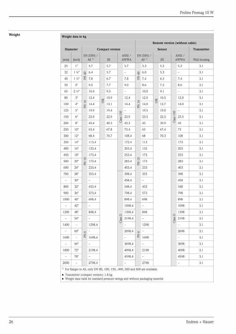
WeightWeight data in kg
Remote version (without cable)
Diameter Compact version Sensor Transmitter
[mm] [inch]
EN (DIN) /
AS 1) JIS
ANSI /
AWWA
EN (DIN) /
AS 1) JIS
ANSI /
AWWA Wall housing
25 1"
PN
40
5.7
10
K
5.7
Cla
ss 1
50
5.7
PN
40
5.3
10
K
5.3
Cla
ss 1
50
5.3 3.1
32 1 ¼" 6.4 5.7 – 6.0 5.3 – 3.1
40 1 ½" 7.8 6.7 7.8 7.4 6.3 7.4 3.1
50 2" 9.0 7.7 9.0 8.6 7.3 8.6 3.1
65 2 ½"
PN
16
10.4 9.5 –
PN
16
10.0 9.1 – 3.1
80 3" 12.4 10.9 12.4 12.0 10.5 12.0 3.1
100 4" 14.4 13.1 14.4 14.0 12.7 14.0 3.1
125 5" 19.9 19.4 – 19.5 19.0 – 3.1
150 6" 23.9 22.9 23.9 23.5 22.5 23.5 3.1
200 8"
PN
10
43.4 40.3 43.3
PN
10
43 39.9 43 3.1
250 10" 63.4 67.8 73.4 63 67.4 73 3.1
300 12" 68.4 70.7 108.4 68 70.3 108 3.1
350 14" 113.4 172.4 113 173 3.1
400 16" 133.4 203.4 133 203 3.1
450 18" 173.4 253.4 173 253 3.1
500 20" 173.4 283.4 173 283 3.1
600 24" 233.4 403.4 233 403 3.1
700 28" 353.4
Cla
ss D
398.4 353C
lass
D398 3.1
– 30" – 458.4 – 458 3.1
800 32" 433.4 548.4 433 548 3.1
900 36" 573.4 798.4 573 798 3.1
1000 40" 698.4 898.4 698 898 3.1
– 42"
PN
6
– 1098.4
PN
6
– 1098 3.1
1200 48" 848.4 1398.4 848 1398 3.1
– 54" – 2198.4 – 2198 3.1
1400 – 1298.4 – 1298 – 3.1
– 60" – 2698.4 – 2698 3.1
1600 – 1698.4 – 1698 – 3.1
– 66" – 3698.4 – 3698 3.1
1800 72" 2198.4 4098.4 2198 4098 3.1
– 78" – 4598.4 – 4598 3.1
2000 – 2798.4 – 2798 – 3.1
1) For flanges to AS, only DN 80, 100, 150...400, 500 and 600 are available.
• Transmitter (compact version): 1.8 kg
• Weight data valid for standard pressure ratings and without packaging material
Proline Promag 10 W
Endress + Hauser 27
Material • Housing: powder-coated die-cast aluminum
• Sensor housing
– DN 25...300: powder-coated die-cast aluminum
– DN 350...2000: coated steel (Amerlock 400)
• Measuring tube
– DN < 350: stainless steel 1.4301 or 1.4306/304L;
Flange material with Al/Zn protective coating
– DN > 300: stainless steel 1.4301 or 1.4306/304;
Flange material with Amerlock 400 coating
• Flanges
– EN 1092-1 (DIN2501): RSt37-2 (S235JRG2) / C22 / Fe 410W B
(DN < 350: with Al/Zn protective coating; DN > 300 with Amerlock 400 coating)
– ANSI: A 105
(DN < 350: with Al/Zn protective coating; DN > 300 with Amerlock 400 coating)
– AWWA: 1.0425 (with Amerlock 400 coating)
– JIS: RSt37-2 (S235JRG2) / HII / 1.0425
(DN < 350: with Al/Zn protective coating; DN > 300 with Amerlock 400 coating)
– AS 2129
– (DN 25, 150, 200, 250, 300, 600) A105 or RSt37-2 (S235JRG2)
– (DN 50, 80, 100, 350, 400, 500) A105 or St44-2 (S275JR)
(DN < 350: with Al/Zn protective coating; DN > 300 with Amerlock 400 coating)
– AS 4087: A105 or St44-2 (S275JR)
(DN < 350 with Al/Zn protective coating; DN > 300 with Amerlock 400 coating)
• Ground disks: 1.4435/316L or Alloy C-22
• Electrodes: 1.4435/316L, Alloy C-22
• Seals: to DIN EN 1514-1
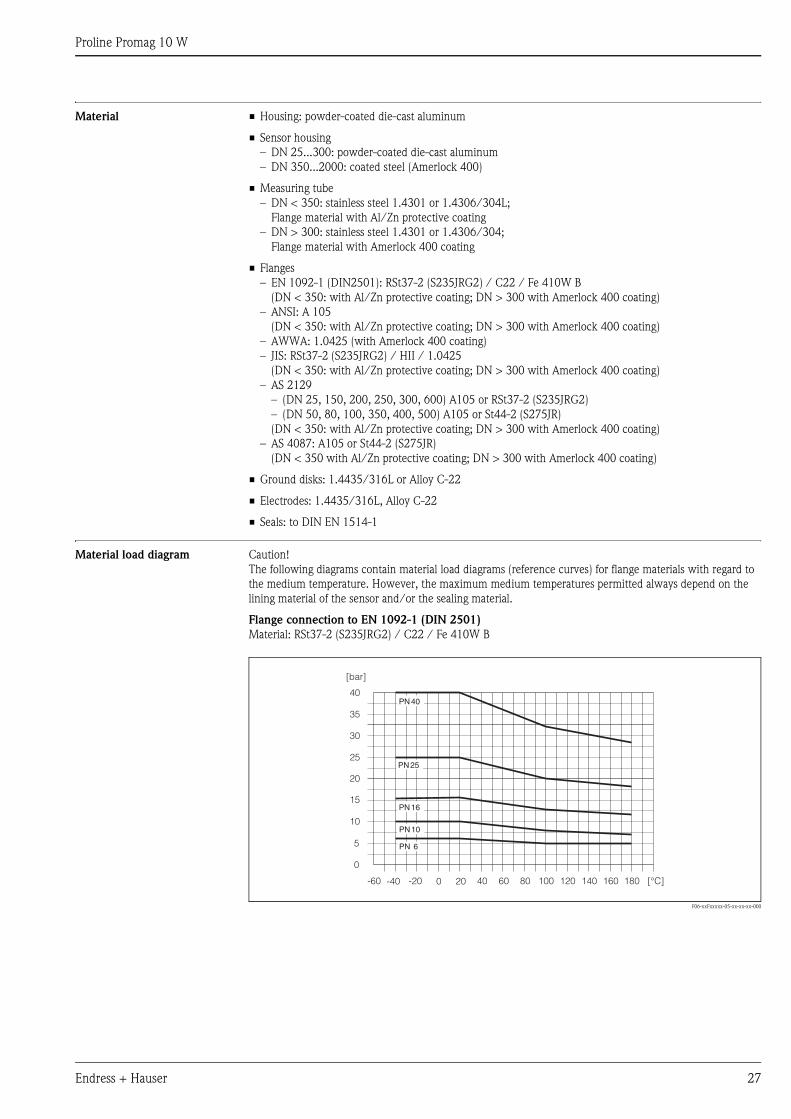
Material load diagram Caution!
The following diagrams contain material load diagrams (reference curves) for flange materials with regard to
the medium temperature. However, the maximum medium temperatures permitted always depend on the
lining material of the sensor and/or the sealing material.
Flange connection to EN 1092-1 (DIN 2501)
Material: RSt37-2 (S235JRG2) / C22 / Fe 410W B
F06-xxFxxxxx-05-xx-xx-xx-000
0
5
10
15
20
25PN25
PN16
PN10
PN 6
35
30
40PN40
[bar]
-60 -40 -20 0 20 40 60 80 100 120 140 160 180 [°C]
Proline Promag 10 W
28 Endress + Hauser
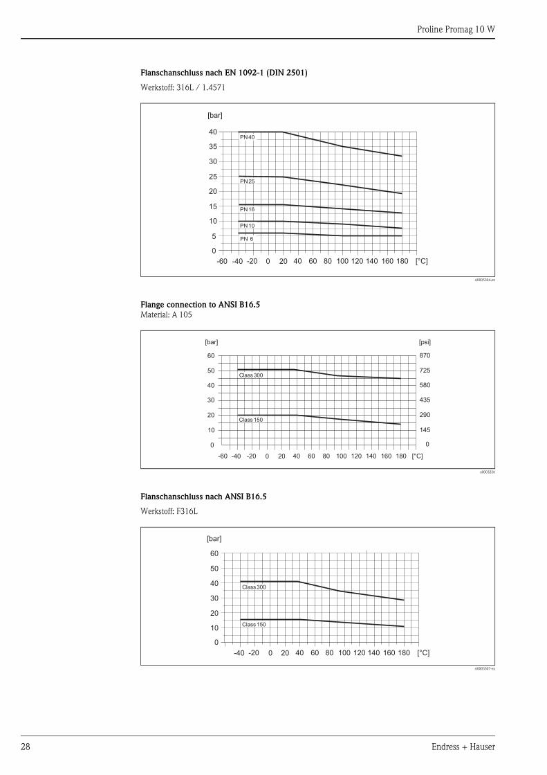
Flanschanschluss nach EN 1092-1 (DIN 2501)
Werkstoff: 316L / 1.4571
A0005304-en
Flange connection to ANSI B16.5
Material: A 105
a0003226
Flanschanschluss nach ANSI B16.5
Werkstoff: F316L
A0005307-en
PN 25
PN 16
PN 10
PN 40
PN 6
0
5
10
15
20
25
35
30
40
[bar]
-60 -40 -20 0 20 40 60 80 100 120 140 160 180 [°C]
Class 300
Class 150
0
10
20
30
40
50
60
[bar]
0
145
290
435
580
725
870
[psi]
-60 -40 -20 0 20 40 60 80 100 120 140 160 180 [°C]
Class 300
Class 150
0
10
20
30
40
50
[bar]
60
-40 -20 0 20 40 60 80 100 120 140 160 180 [°C]
Proline Promag 10 W
Endress + Hauser 29
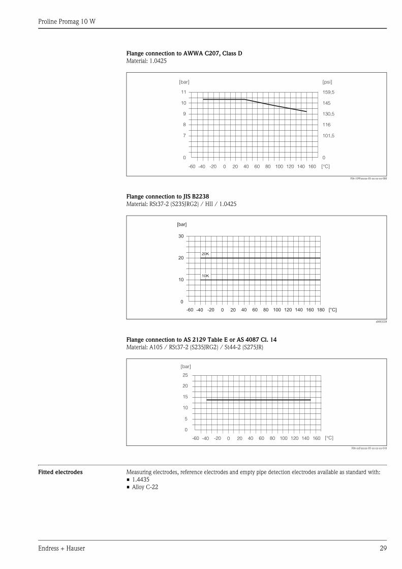
Flange connection to AWWA C207, Class D
Material: 1.0425
F06-10Wxxxxx-05-xx-xx-xx-000
Flange connection to JIS B2238
Material: RSt37-2 (S235JRG2) / HII / 1.0425
a0003228
Flange connection to AS 2129 Table E or AS 4087 Cl. 14
Material: A105 / RSt37-2 (S235JRG2) / St44-2 (S275JR)
F06-xxFxxxxx-05-xx-xx-xx-010
Fitted electrodes Measuring electrodes, reference electrodes and empty pipe detection electrodes available as standard with:
• 1.4435
• Alloy C-22
0
7
8
9
10
11
[bar]
0
101,5
116
130,5
145
159,5
[psi]
-60 -40 -20 0 20 40 60 80 100 120 140 160 [°C]
0
10
20
10K
20K
30
[bar]
-60 -40 -20 0 20 40 60 80 100 120 140 160 [°C]180
0
5
10
15
20
25
[bar]
-60 -40 -20 0 20 40 60 80 100 120 140 160 [°C]
Proline Promag 10 W
30 Endress + Hauser
Process connections Flange connection:
• EN 1092-1 (DIN 2501), < DN 350 form A, > DN 300 form B
(Dimensions to DIN 2501, DN 65 PN 16 and DN 600 PN 16 exclusively to EN 10921)
• ANSI B16.5
• AWWA C 207, Class D
• JIS B2238
• AS 2129 Table E
• AS 4087 Cl. 14
Surface roughness Electrodes with 1.4435 (AISI 316L), Alloy C-22: ≤ 0.3...0.5 μm
(All data refer to parts in contact with medium)
Human interface
Display elements • Liquid crystal display: unilluminated, two-line, 16 characters per line
• Display (operating mode) preconfigured: volume flow and totalizer status
• 1 totalizer
Operating elements Local operation via three keys (S, O, F)
Remote operation Operation via HART protocol and ToF Tool - Fieldtool Package
Certificates and approvals
CE mark The measuring system is in conformity with the statutory requirements of the EC Directives.
Endress+Hauser confirms successful testing of the device by affixing to it the CE mark.
C-tick mark The measuring system meets the EMC requirements of the Australian Communications Authority (ACA)
Ex approval Information about currently available Ex versions (ATEX, FM, CSA, etc.) can be supplied by your Endress
+Hauser Sales Center on request. All explosion protection data are given in a separate documentation which
is available upon request.
Other standards and
guidelines
• EN 60529
Degrees of protection by housing (IP code)
• EN 61010
Protection Measures for Electrical Equipment for Measurement, Control, Regulation and Laboratory
Procedures.
• EN 61326/A1 (IEC 1326)
“Emission in accordance with requirements for Class A”.
Electromagnetic compatibility (EMC requirements)
• ANSI/ISA-S82.01
Safety Standard for Electrical and Electronic Test, Measuring, Controlling and related Equipment - General
Requirements. Pollution degree 2, Installation Category II.
• CAN/CSA-C22.2 No. 1010.1-92
Safety requirements for Electrical Equipment for Measurement and Control and Laboratory Use.
Pollution degree 2, Installation Category II
Pressure measuring device
approval
Measuring devices with a nominal diameter smaller than or equal to DN 25 correspond to Article 3(3)
of the EC Directive 97/23/EC (Pressure Equipment Directive) and have been designed and manufactured
according to good engineering practice. Where necessary (depending on the medium and process pressure),
there are additional optional approvals to Category II/III for larger nominal diameters.
Proline Promag 10 W
Endress + Hauser 31
Ordering informationYour Endress
+Hauser service organization can provide detailed ordering information and information on the order codes on
request.
AccessoriesVarious accessories, which can be ordered separately from Endress+Hauser, are available for the transmitter
and the sensor. Your Endress+Hauser service organization can provide detailed information on the order codes
in question.
Documentation • System Information Promag 10 (SI042D/06/en)
• Operating Instructions Promag 10 (BA082D/06/en)
Registered trademarksKALREZ® and VITON®
Registered trademarks of E.I. Du Pont de Nemours & Co., Wilmington, USA
TRI-CLAMP®
Registered trademark of Ladish & Co., Inc., Kenosha, USA
HART®
Registered trademark of the HART Communication Foundation, Austin, USA
ToF Tool - Fieldtool® Package, Fieldcheck®, Applicator®
Registered or registration-pending trademarks of Endress+Hauser Flowtec AG, Reinach, CH

Proline Promag 10 W
Instruments International
Endress+HauserInstruments International AGKaegenstrasse 24153 ReinachSwitzerland
Tel. +41 61 715 81 00Fax +41 61 715 25 [email protected]
TI093D/06/en/08.09
71101434
FM+SGML6.0 ProMoDo