
Fletcher Residential Limited - Auckland Council · Three Kings Renewal Stormwater Management Plan...
72
Auckland Wellington Christchurch PATTLE DELAMORE PARTNERS LTD Three Kings Renewal Stormwater Management Plan - Option 15H1 Fletcher Residential Limited solutions for your environment
Transcript of Fletcher Residential Limited - Auckland Council · Three Kings Renewal Stormwater Management Plan...

Auckland Wellington Christchurch
PATTLE DELAMORE PARTNERS LTD
Three Kings Renewal Stormwater Management Plan - Option 15H1
Fletcher Residential Limited
solutions for your environment
Three Kings Renewal Stormwater Management Plan – Option 15H1
π Prepared for
Fletcher Residential Limited
π September 2014
PATTLE DELAMORE PARTNERS LTD
Level 4, PDP House
235 Broadway, Newmarket, Auckland 1023
PO Box 9528, Auckland 1149, New Zealand
Tel +9 523 6900 Fax +9 523 6901
Web Site http:/ / www.pdp.co.nz
Auckland Wellington Christchurch
solutions for your environment


P A T T L E D E L A M O R E P A R T N E R S L T D i i
T H R E E K I N G S R E N E W A L S T O R M W A T E R M A N A G E M E N T P L A N - O P T I O N 1 5 H 1
AJ456300R001 STORMWATER MANAGEMENT PLAN 15H1 - REV 3.DOCX
Limitations:
This report has been prepared on the basis of information provided by Fletcher Residential Ltd and others (not directly contracted by PDP for the work), including dKO Architecture and Surfacedesign Inc. PDP has not independently verified the provided information and has relied upon it being accurate and sufficient for use by PDP in preparing the report. PDP accepts no responsibility for errors or omissions in, or the currency or sufficiency of, the provided information. This report has been prepared by PDP on the specific instructions of Fletcher Residential Ltd for the limited purposes described in the report. PDP accepts no liability if the report is used for a different purpose or if it is used or relied on by any other person (except Auckland Council for the purposes of assessing the plan change application). Any such use or reliance will be solely at their own risk.
P A T T L E D E L A M O R E P A R T N E R S L T D i i i
T H R E E K I N G S R E N E W A L S T O R M W A T E R M A N A G E M E N T P L A N - O P T I O N 1 5 H 1
AJ456300R001 STORMWATER MANAGEMENT PLAN 15H1 - REV 3.DOCX
Executive Summary
The Three Kings Renewal requires a plan change to the operative Auckland District Plan
(Isthmus Section) to enable the comprehensive redevelopment of the former quarry lands
at Three Kings. The development includes open space areas, a comprehensive roading
and pathway network, apartment blocks of differing heights, and terraced housing. The
development is expected to house between 3,500 and 4,275 people.
This report addresses development layout 15H1 which provides a comprehensive
development for both the former Three Kings Quarry owned by Fletcher Concrete and
Infrastructure Ltd and an area of adjoining land to the south previously operated as a
quarry by the former Mt Roskill Borough Council.
Pattle Delamore Partners Ltd (PDP) was engaged to develop the stormwater management
concept for the development and demonstrate that the residential development enabled
by the plan change can proceed. The development will require raising the existing base of
the quarry using imported fill. The depth of fill will vary to a maximum of 28 m below
finished ground level. The development will be at a level between 15 m and 17 m below
the surrounding land with stormwater to be disposed of by soakage. While the completed
fill level on the site will be above the natural groundwater levels (without the need for
pumping), the differential ground levels mean the management of stormwater is a key
consideration in the overall development design.
This report details the design and modelling of surface and groundwater to assess
stormwater effects and using this, sets out the stormwater management plan for the
proposed development. The report includes:
• Catchment hydrology and main flow paths;
• Determination of required flood storage volumes and levels;
• Location and nature of flood storage zones;
• Stormwater quality treatment; and
• Incorporation of soakage and final discharge of stored water.
A conservative approach has been taken in the design of the stormwater management
measures set out in the stormwater management plan, to ensure the plan is feasible and
effective in the long term. This approach includes making conservative assumptions
concerning catchment hydrology, soakage rates, flood storage, and flood freeboard.
This stormwater management plan concludes that:
• The groundwater rise due to infiltration of water during the 10-year and 100-year
ARI (Average Recurrence Interval) rainfall events is 1.5 m and 2 m, respectively.
Therefore, it has been assumed that soil is saturated up to RL 58.0 m and RL
58.5 m for the 10-year and 100-year rainfall events, respectively, and no flood
storage is used below these levels.
• The 10-year and 100-year ARI rainfall events can be appropriately managed with
discharges to soakage facilities provided along the eastern wetland, beneath the
sports field, and at a number of individual apartment blocks.
P A T T L E D E L A M O R E P A R T N E R S L T D i v
T H R E E K I N G S R E N E W A L S T O R M W A T E R M A N A G E M E N T P L A N - O P T I O N 1 5 H 1
AJ456300R001 STORMWATER MANAGEMENT PLAN 15H1 - REV 3.DOCX
• Flood storage is available to manage the 100-year ARI runoff volume with
appropriate freeboard provided to all habitable floors. The flood level is RL 60.0
m at the sports field and RL 61.6 m in the northern cell of the eastern wetland.
• The freeboard available is such that all of the rainfall volume (not runoff
volume) from a 100-year ARI rainfall event can be accommodated below all
habitable floors.
• In order to avoid flooding on the sports field in a 10-year ARI rainfall event, the
field level has been set at RL 59.0 m. The 10-year maximum flood level will be
RL 61.3 m in the northern cell of the eastern wetland channel, with some
overland flow paths elsewhere at higher levels.
• Stormwater quality treatment is provided in several locations: Pond A, the
eastern wetland cells, and in individual swales and rain-gardens for some paved
areas and roads. High quality roof water will be achieved through the use of non-
exposed metal products such as pre-painted steel.
While further work is necessary to refine the design of the stormwater management
system, PDP are confident that stormwater from the redevelopment of the site can be
appropriately managed. It is expected that the further work will lead to reductions in the
flood storage required for the development.
As such, it is considered that the proposed stormwater design concept will comfortably
cater for the modelled rainfall events and that the residential development enabled by the
Plan Change is supported in terms of stormwater management.
P A T T L E D E L A M O R E P A R T N E R S L T D v
T H R E E K I N G S R E N E W A L S T O R M W A T E R M A N A G E M E N T P L A N - O P T I O N 1 5 H 1
AJ456300R001 STORMWATER MANAGEMENT PLAN 15H1 - REV 3.DOCX
Table of Contents
S E C T I O N P A G E
Executive Summary iii
1.0 Introduction 1 1.1 Background 1 1.2 Scope of Work 2
2.0 Existing State 4 2.1 Catchment History 4 2.2 Geology 6 2.3 Groundwater 6 2.4 Surface Water Catchment 7
3.0 Water Modelling 8 3.1 Surface Water Model 8 3.2 Groundwater Model 12
4.0 Design Considerations 20 4.1 General 20 4.2 Design Standards 21 4.3 Options Analysis 24
5.0 Proposed Stormwater Management 25 5.1 Design Summary 25 5.2 Main Development System 26 5.3 Individual Apartment Blocks 31 5.4 Multiple Flood Events 32 5.5 Operational Issues 33
6.0 Resource Management Approach 34 6.1 Plan Change Provisions 34
7.0 Opportunities Provided by this Proposal 36 7.1 Soakage for Surrounding Areas 36 7.2 Flood Storage 36
8.0 Conclusions 36
9.0 References 37
P A T T L E D E L A M O R E P A R T N E R S L T D v i
T H R E E K I N G S R E N E W A L S T O R M W A T E R M A N A G E M E N T P L A N - O P T I O N 1 5 H 1
AJ456300R001 STORMWATER MANAGEMENT PLAN 15H1 - REV 3.DOCX
Table of Figures
In body of report:
Figure 1: Three Kings Quarry Image from 2014 5
Figure 2: Seasonal Groundwater Fluctuation in the Cone (BH2B, before dewatering) 14
Figure 3: Model Grid and Boundary Conditions 16
Figure 4: Calibration of Transient Groundwater Model 18
Figure 5: Groundwater Level Rise after 100 year ARI Rainfall Event 19
In Appendix A:
dKO Architecture Option 15H1 Illustrative Layout
Figure 6: Quarry Geology Map
Figure 7: Catchment Map for Groundwater Contributions
Figure 8: Catchment Map for Rainfall Runoff
Tonkin & Taylor Figure 2 (Project Number 25141.003)
Figure 9: Stormwater Management Concept
Figure 10: Eastern Wetland Channel Sections
Figure 11: Flood Storage Areas
Table of Tables
Table 1: Summary of inputs to HEC-HMS Model 10
Table 2: Design 24 hour rainfall events 11
Table 3: Average Pre-dewatering Groundwater Levels in Scoria/Basalt within the Three Kings Crater 13
Table 4: Steady State Calibrated Parameter 17
Table 5: Groundwater Mass Balance 17
Table 6: Storage provided for 10 and 100 year ARI Runoff Volumes 28
Table 7: Flood Levels in the 100 year ARI Rainfall Event 29
Table 8: Individual Apartment Blocks Treatment Train to Soakage 31
Table 9: Proposed Plan Change Provisions 35

P A T T L E D E L A M O R E P A R T N E R S L T D v i i
T H R E E K I N G S R E N E W A L S T O R M W A T E R M A N A G E M E N T P L A N - O P T I O N 1 5 H 1
AJ456300R001 STORMWATER MANAGEMENT PLAN 15H1 - REV 3.DOCX
Appendices
Appendix A: Figures
Appendix B: Surface Water Model Results
Appendix C: Soakage Test Results: Mt Eden Road / Upper Development Area
Appendix D: Matrix of Stormwater Management Options
P A T T L E D E L A M O R E P A R T N E R S L T D 1
T H R E E K I N G S R E N E W A L S T O R M W A T E R M A N A G E M E N T P L A N - O P T I O N 1 5 H 1
AJ456300R001 STORMWATER MANAGEMENT PLAN 15H1 - REV 3.DOCX
1.0 Introduction
1.1 Background
The Three Kings Quarry, located south of Mount Eden in Auckland, has been excavated for
scoria since the 1840s and began the process of filling in 2012. Fletcher Concrete and
Infrastructure Ltd (Fletcher) has owned and operated the 15.2 ha site since 1922 and
through its sister company Fletcher Residential Ltd intends to develop it into a residential
precinct including apartments, townhouses, and open space including sports fields. The
development is expected to house between 3,500 and 4,275 people.
This report addresses development layout 15H1 which provides a comprehensive
development for both the former Three Kings Quarry land owned by Fletcher and areas of
adjoining land to the south previously operated as a quarry by the former Mt Roskill
Borough Council. The site layout plan has been developed by dKO Architecture and
Surfacedesign Inc. and is shown in Appendix A.
The Three Kings Renewal development requires a plan change to the operative Auckland
District Plan (Isthmus Section) to enable the redevelopment.
Pattle Delamore Partners (PDP) has been involved in the development and operation of
the Three Kings Quarry for Winstone Aggregates since 1996. PDP has also been the
primary consultant assessing the groundwater resources of the wider Auckland Volcanic
field for Auckland Council and former Auckland City Council. Previous work has included:
• Assessment of the geology and groundwater regime in the Three Kings area for
Winstone Aggregates to assess dewatering regimes and groundwater
management for quarry operations.
• Preparing the Assessment of Effects on the Environment related to groundwater
for obtaining the groundwater dewatering consent for the continued operation of
the quarry.
• Preparing the Assessment of Effects on the Environment related to groundwater
for filling the quarry in 2011.
• Assessment and modelling of the geology and groundwater within the Auckland
Volcanic Field across the Auckland Isthmus in the “Global Aquifer Study” (GAS)
for the former Auckland City Council. This informed catchment management with
respect to soakage across the isthmus and particularly the Meola catchment
(within which Three Kings is located).
• Assessment of the effects of stormwater soakage discharges and soakage
opportunities throughout the Auckland Volcanic Field for Auckland Council and
private clients.
• Preparation of the Soakage Design Manual for the Auckland City Council in 2003
and an update to this for Auckland Council to expand its use to the wider
Auckland region in 2013.
P A T T L E D E L A M O R E P A R T N E R S L T D 2
T H R E E K I N G S R E N E W A L S T O R M W A T E R M A N A G E M E N T P L A N - O P T I O N 1 5 H 1
AJ456300R001 STORMWATER MANAGEMENT PLAN 15H1 - REV 3.DOCX
• Assessment of stormwater contaminant loads and development of catchment
management approaches for stormwater quality across the Auckland Isthmus for
the former Auckland City Council for its network consent applications.
PDP was engaged to assess the potential effects of stormwater discharges, and develop
the stormwater management concept for the development to demonstrate that the
development enabled by the plan change can proceed. The development will require
raising the existing base of the quarry using imported fill. The depth of fill will be a
maximum of 28 m below the finished ground level. The development will be between 15
and 17 m below the surrounding land with no surface water outflow. Therefore, the
management of stormwater is a key consideration in the design of the layout and the lots.
1.2 Scope of Work
Preliminary design has been carried out for a number of alternative stormwater
management options.
Earlier development layouts included two lakes. These were considered for their potential
to provide flood storage, water quality improvement and amenity value. The lakes would
have required lining to maintain water levels (with low groundwater levels) and were
considered to have potential algal problems. This, combined with feedback from
consultation with iwi about water quality, led to the development of a stormwater
approach which includes a wetland system instead. The wetland system will provide
treatment to a wider range of stormwater contaminants, compared to the lake and is the
preferred approach in terms of stormwater quality management.
Two key groundwater scenarios have been proposed; maintaining an artificially reduced
groundwater level via pumping (referred to as the ‘long-term pumping’ scenario) to
improve soakage and underground storage potential; and allowing groundwater levels to
naturally develop (referred to as the ‘no long-term pumping’ scenario). The ‘long-term
pumping’ scenario is less critical for stormwater design as surplus underground storage is
available for soakage due to lower groundwater levels. This report focuses solely on the
‘no long-term pumping’ scenario to demonstrate that the development is feasible using
the more conservative groundwater conditions.
Stormwater modelling was carried out based on the development layout Option 15H1
shown in the dKO Architecture illustrative layout. This layout provides a comprehensive
development plan for both the former Three Kings Quarry land owned by Fletcher and an
area of adjoining land to the south previously operated as a quarry by the former Mt
Roskill Borough Council.
Due to the low elevation of the Three Kings Quarry land, stormwater management
planning had to account for the effects of both surface water and groundwater flows.
Stormwater and groundwater models were constructed (in HEC-HMS and Visual Modflow
respectively) to develop a comprehensive understanding of the behaviour of water in the
former quarry. Climate change was accounted for in the models.
P A T T L E D E L A M O R E P A R T N E R S L T D 3
T H R E E K I N G S R E N E W A L S T O R M W A T E R M A N A G E M E N T P L A N - O P T I O N 1 5 H 1
AJ456300R001 STORMWATER MANAGEMENT PLAN 15H1 - REV 3.DOCX
This report details the design and modelling of surface and groundwater and, using this,
sets out the stormwater management plan for the proposed development including:
• Catchment hydrology and main flow paths;
• Determination of required flood storage volumes and levels;
• Location and nature of flood storage zones;
• Stormwater quality treatment; and
• Incorporation of soakage and final discharge of stored water.
The stormwater management plan will inform the development of detailed site levels and
piped infrastructure design.
A conservative approach has consistently been taken to develop the stormwater
management plan, to ensure that the plan is feasible and effective in the long term.
Key conservative assumptions include:
• Rainfall values used are 10 to 25% higher than required by Auckland Council’s
“Guidelines for Stormwater Runoff Modelling in the Auckland Region” Technical
Publication 108 (TP108).
• Short term groundwater levels have been accounted for and assume that water
from the surrounding groundwater catchment instantaneously contributes to an
increased groundwater level (at the same time as surface water arrives at the
flood storage areas). In reality groundwater levels will rise later due to the time
water takes to infiltrate through the ground.
• No pumping of groundwater is allowed for with all flood storage provided above
the pre-quarry pumping groundwater levels (although this is an opportunity that
could be used to provide extremely significant additional water storage capacity).
• Zero soakage has been allowed for from the main flood storage areas during the
rainfall event – actual storage volumes are expected to be reduced following on
site testing and flow routing.
• Freeboard has been increased to ensure no flooding of habitable floors for a
hypothetical case of zero surface infiltration and zero soakage. That is, floor
levels are above the water level of the 100-year ARI rainfall event even if there
were no infiltration or soakage in the development.
• Sediment treatment and filtering is provided to maintain soakage capacity in the
long term.
While no pumping of groundwater has been conservatively assumed in developing the
stormwater management plan for the quarry, there is potential for additional soakage and
ongoing pumping would provide a significant opportunity for flood storage in the
unsaturated zone. In addition, as much of the existing public drainage network
surrounding the quarry is a combined sewer system, there is significant potential to divert
stormwater away from the combined sewer to soakage and, as a result, improve the
capacity of the sewer. The Auckland Council Stormwater Unit and Watercare are currently
considering these opportunities.
P A T T L E D E L A M O R E P A R T N E R S L T D 4
T H R E E K I N G S R E N E W A L S T O R M W A T E R M A N A G E M E N T P L A N - O P T I O N 1 5 H 1
AJ456300R001 STORMWATER MANAGEMENT PLAN 15H1 - REV 3.DOCX
2.0 Existing State
2.1 Catchment History
Three Kings is situated at the top of the Meola catchment. The catchment has complex
geology with the groundwater catchment underlying a wide volcanic area across the
isthmus.
The top of the Meola surface water catchment follows Mt Eden Road, directly adjacent to
the quarry, and the Mt Eden area to the north. The surface water catchment includes the
Three Kings area and generally heads westwards, taking in parts of Sandringham,
Balmoral, Mt Albert, St Lukes and Chamberlain Park before discharging at Meola Reef.
The groundwater catchment is wider and covers parts of the Meola, Motions, Newmarket,
Epsom and Central City surface water catchments. The extent of the volcanic aquifer
across central Auckland is approximately 5500 ha, or approximately 38% of the isthmus
area.
Over time, soakage systems have generally developed to make use of those parts of the
aquifer with good soakage rates although the extent of the “soakage system” remains
significantly smaller (approximately 2800 ha) than the extent of the aquifer. Within the
Meola catchment the basalt aquifer, which provides the primary soakage capability,
covers approximately 52% of the surface catchment area. Of the remaining area,
combined sewers service approximately 40% of the catchment and separated stormwater
systems 10%.
Parts of Meola have been developing since the early 1900s. The Meola catchment is
dominated by residential landuse, which accounts for 80% of the catchment area, with
open space (10%) and industrial (6%) being the other significant landuses.
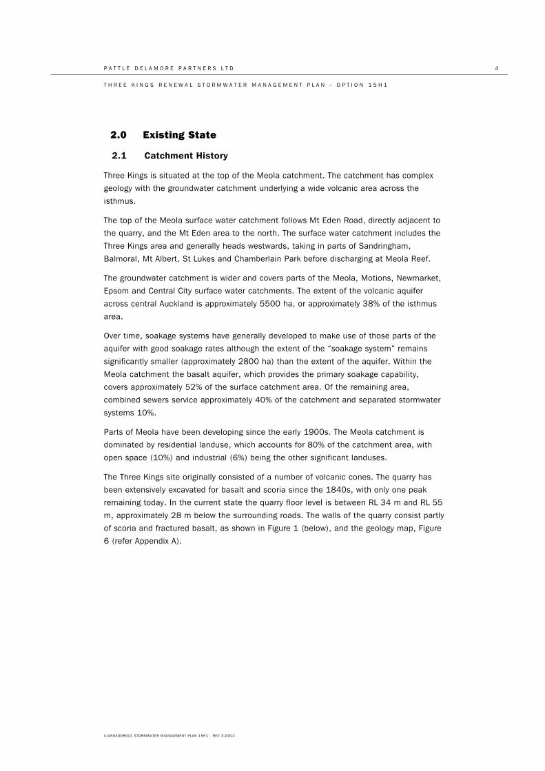
The Three Kings site originally consisted of a number of volcanic cones. The quarry has
been extensively excavated for basalt and scoria since the 1840s, with only one peak
remaining today. In the current state the quarry floor level is between RL 34 m and RL 55
m, approximately 28 m below the surrounding roads. The walls of the quarry consist partly
of scoria and fractured basalt, as shown in Figure 1 (below), and the geology map, Figure
6 (refer Appendix A).
P A T T L E D E L A M O R E P A R T N E R S L T D 5
T H R E E K I N G S R E N E W A L S T O R M W A T E R M A N A G E M E N T P L A N - O P T I O N 1 5 H 1
AJ456300R001 STORMWATER MANAGEMENT PLAN 15H1 - REV 3.DOCX
Figure 1: Three Kings Quarry Image from 2014
P A T T L E D E L A M O R E P A R T N E R S L T D 6
T H R E E K I N G S R E N E W A L S T O R M W A T E R M A N A G E M E N T P L A N - O P T I O N 1 5 H 1
AJ456300R001 STORMWATER MANAGEMENT PLAN 15H1 - REV 3.DOCX
2.2 Geology
The main features of the pre-volcanic topography in the Auckland area were the
Waitemata Valley (subsequently drowned to form the current Waitemata Harbour), the
Manukau Valley (current Manukau Harbour) and the main dividing ridge between the two
valley systems. The Auckland Volcanic Group erupted basalt lavas, scoria, tuff and ash
through, and accumulated on, the pre-existing ridge and valley system.
The Three Kings Quarry sits approximately centrally within the Three Kings volcanic crater.
The crater is a hole within the older surrounding Waitemata and Tauranga Group rocks,
which at the surface is approximately 1000 m in diameter and takes the approximate
form of an ice-cream cone. This crater was filled with volcanic material - primarily basaltic
lava and scoria - during the eruptive phases of the Three Kings volcano.
During the initial explosive eruptive phases of the Three Kings volcano the pre-existing
Waitemata and Tauranga Group rocks were shattered and blown out of the crater to be
deposited as tuff in a raised ring around the edge of the crater. The height of this ring
varies around the crater and in the north, around Landscape Road to the west of Mt Eden
Road, there is a low point. Basalt lava, which ponded within the crater, eventually spilled
over this low point. From there it joined with basalt flows from One Tree Hill, Mt Eden and
Mt Albert volcanoes to infill the Meola Valley and form the Meola Reef in the Waitemata
Harbour.
A number of scoria cones also formed within the crater. Most of these have been
removed or heavily modified by quarrying at, and in the vicinity of, the site, although the
cone known as Big King remains adjacent to the western boundary of the quarry.
2.3 Groundwater
Groundwater flow in the basalt aquifers typically follows the drainage direction of the pre-
volcanic topography. The groundwater flows within the base of the basalt down the
paleovalley system towards the harbours. The main dividing ridge separates groundwater
that flows towards the Waitemata Harbour from groundwater that flows towards the
Manukau Harbour. The GAS model (PDP, 2005) predicts aquifer groundwater levels and
the ultimate discharge locations of groundwater and can be used to infer soakage
potential across the Greater Western Springs aquifer area.
Around the quarry, due to the high permeability of the volcanic materials and the low
permeability of the surrounding tuff and Waitemata and Tauranga Group rocks, rainfall
over the crater soaks into the ground to recharge the groundwater which collects within
the crater. This soakage occurs either directly through exposed ground or indirectly
through stormwater runoff directed to soakage devices. Groundwater levels in the crater
stabilise when the inflows to the crater (in the form of rainfall recharge) are balanced by
outflows from the crater. Currently outflows are in the form of the groundwater abstraction
for quarry dewatering and are currently balanced by inflows. Prior to the advent of quarry
dewatering, groundwater levels within the crater were at approximately RL 56.5 m, (23 m
higher than present) and outflows occurred (within the high permeability lava flows) by
P A T T L E D E L A M O R E P A R T N E R S L T D 7
T H R E E K I N G S R E N E W A L S T O R M W A T E R M A N A G E M E N T P L A N - O P T I O N 1 5 H 1
AJ456300R001 STORMWATER MANAGEMENT PLAN 15H1 - REV 3.DOCX
spilling over the low point in the tuff ring (at approximately RL 48m) in the vicinity of
Landscape Road. This groundwater would then have migrated through the basalt flows
infilling the former Meola Valley and eventually discharged to the Waitemata Harbour
close to the Meola reef.
Dewatering of the quarry takes place from a borehole located along the southern
boundary of the quarry ("The Three Kings Well"). The abstracted groundwater is then
discharged into the reticulated stormwater network, to the south-east, which ultimately
discharges to the Manukau Harbour. Dewatering began in March 1999 and, since October
2002, has been maintained to hold groundwater levels at the bore, and consequently
within the crater, steady at an elevation between RL 34 m and 35 m. The average
pumping rate required to do this is approximately 2500 m3/day.
Approximately 1.13 km2 (80%) of the urban groundwater catchment to the quarry is
drained via dedicated stormwater reticulation and combined sewers (which do not
discharge to the quarry). The remainder of the urban catchment is assumed to be treated
via soakage which discharges to groundwater. Direct infiltration of stormwater into the
quarry floor also contributes to groundwater.
2.4 Surface Water Catchment
The high point of the Meola surface water catchment is approximately bounded by Mt
Eden Road around the quarry, St Andrews Rd and then Mt Eden Rd again to the north.
The catchment includes the Three Kings area and generally heads westwards, taking in
parts of Sandringham, Balmoral, Mt Albert, St Lukes, Chamberlain Park and discharges at
Meola Reef.
The main piped drainage system for the Meola catchment consists of combined sewers
for stormwater and wastewater. In the upper half of the catchment, drainage is provided
by the Edendale Branch Sewer and the Mt Albert Branch Sewer. The Edendale Branch
Sewer services the parts north of Balmoral Rd and, in the top of the catchment, north of
Landscape Rd (approximately). The Mt Albert Branch Sewer caters for the southern part of
the upper catchment including the Three Kings area.
Soakage is a significant component of the drainage for the catchment, servicing
approximately 50% of the surface area. Soakage and combined sewer areas overlap.
Properties may discharge their stormwater to either the combined sewer or soakage
depending upon their historical drainage, geological setting, physical constraints and
council re-development requirements.
In the areas around Three Kings quarry, the combined sewer system services development
to the west (around McCullough and Smallfield Avenues) and Mt Eden Rd itself. To the
south of the site, a 300 mm dia combined sewer runs westwards and increases in size
incrementally to a maximum 1950 mm dia pipe at Haverstock Road on the southern
branch of the Meola Creek. Here, a constructed overflow throttles storm flows and they
overflow to the Meola Creek. The continuation pipe, which services dry weather flow, is a
450 mm dia pipe. Combined sewer overflows are a significant issue within the catchment.
P A T T L E D E L A M O R E P A R T N E R S L T D 8
T H R E E K I N G S R E N E W A L S T O R M W A T E R M A N A G E M E N T P L A N - O P T I O N 1 5 H 1
AJ456300R001 STORMWATER MANAGEMENT PLAN 15H1 - REV 3.DOCX
The two main constructed overflows within the catchment are at Haverstock Road and
Lyons Ave.
In the longer term two significant projects are proposed by Auckland Council to change
the drainage in the Meola catchment. A flood relief pipe system is being investigated to
provide high flow capacity, and, a new wastewater tunnel, the Central Interceptor tunnel,
is proposed by Watercare to provide additional downstream trunk sewer capacity.
The area to the east (between Mt Eden Rd and St Andrews Rd) is drained by a separated
stormwater system to a 1200 mm dia tunnel connected to the stormwater system
draining towards Royal Oak and Onehunga.
Soakage is not used to a great extent in the local area around the quarry. This may be
due to tuff (volcanic ash) covering the basalt and scoria deposits thereby limiting the near
surface soakage capacity. PDP has investigated the soakage capacity of sites adjacent to
Mt Eden Rd and found good soakage rates (40 to 60 L/s per borehole). Auckland Council
is currently investigating potential soakage in the McCullough, Smallfield Avenues area.
Surface water drains to the quarry low point from within the quarry footprint and from
external areas outside quarry footprint. These external areas are; part of the Three Kings
Reserve to the west, the upper corner of the site which is currently used as the entrance
to the quarry and for commercial buildings, part of the residential development around
Smallfield Avenue and playing field to the west of the quarry. Stormwater flows from the
residential areas to the south-west of the development may occur once the capacity of
the combined sewer system in that area was exceeded.
Flows from the Three Kings shopping centre carpark to the south are piped directly to the
land previously operated as a quarry by the Mt Roskill Borough Council. Water flowing on
to this land would pond and drain by informal soakage into the ground.
3.0 Water Modelling
3.1 Surface Water Model
Surface water modelling was carried out in accordance with Auckland Council’s TP 108
and the associated recommended HEC HMS modelling software. A catchment map is
shown in Figure 8 (refer Appendix A). Key model parameters are described below.
3.1.1 Catchment Layout
The stormwater management plan maintains the current flow patterns and caters for
existing offsite flows. In broad terms there are three catchments; Catchment A for the
southern external areas, Grahame Breed Drive and apartments to the south-west,
Catchment B for apartments around the sports field and Catchment C for northern
development areas.
As shown in Figure 8, three primary storage areas are proposed in the southern part of
the development: a south-western pond/wetland (Pond A), the central sports field (Sports
Field B), and a south-western park area (Area C). Pond A provides permanent surface
P A T T L E D E L A M O R E P A R T N E R S L T D 9
T H R E E K I N G S R E N E W A L S T O R M W A T E R M A N A G E M E N T P L A N - O P T I O N 1 5 H 1
AJ456300R001 STORMWATER MANAGEMENT PLAN 15H1 - REV 3.DOCX
storage while the sports field and Area C flood only during events greater than the 10 year
ARI rainfall event. There is no physical boundary proposed between the flood storage
provided by the sports field and Area C.
A number of catchments outside the quarry also discharge stormwater to the
development. Overland flow from the catchment south of the quarry (Smallfield Avenue)
drains to Pond A. Runoff from the carpark at Three Kings Plaza will be piped underground
directly to Sports Field B. Runoff from a portion of Big King Reserve, to the northwest of
the site, is conveyed to Area C as well as smaller portions to Pond A and Sports Field B.
Northern areas (draining to Area C) are conveyed through an eastern channel/wetland on
the eastern edge of the eastern road. This wetland is divided into four cells identified as
wetland cells 1, 2, 3, 4. The modelling is also used to determine:
• an appropriate size and conveyance capacity through this eastern wetland;
• if these flood storage areas A, B and C are sufficient, and
• the need for, and size of, any further flood storage areas that may be required.
3.1.2 Sub-catchment Characteristics
The quarry floor will be raised to its finished level with compacted engineered fill. Pervious
areas overlying this fill have been characterised as having a SCS curve number (CN) of
74, which reflects the relatively low infiltration potential of compacted engineered fill and
a conservative representation of future topsoils. A CN of 74 is typical for Waitemata
Group soils, which share similar properties to the material used for filling. As engineered
fill is to be used, there is also some control over the properties ensuring that some
infiltration capacity will be provided. Paved and road areas were assigned a CN of 98.
External sub-catchments that overlie basalt or scoria were assigned a CN of 39 to reflect
their high infiltration potential. Areas that are already above engineered fill were assigned
a CN of 74.
Sub-catchments were assigned a composite CN based on an assumed impervious
percentage, estimated from the layouts provided in option 15H1. Residential areas were
typically assumed to be 50% impervious, and road reserves were assumed to be 90%
impervious. Apartments and immediately adjacent areas may be up to 95% impervious.
Where possible, areas outside of the quarry were measured accurately from aerial
photographs.
Initial abstractions represent the depth of water that an area can infiltrate at the
beginning of a storm. Impervious areas were assumed to have zero initial abstraction, and
pervious areas were assumed to have 5 mm. A composite initial abstraction was
determined based on the proportion of impervious cover.
Lag times represent the travelling time for the water and determine how much the peak of
the runoff is distributed. Lag times depend on factors such as travelling distance, slope
and nature of the conveyance and affect only peak flow rates, not runoff volumes.
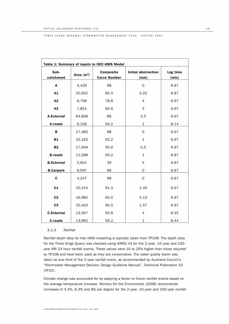
Table 1 summarises the inputs for the HEC-HMS model.
P A T T L E D E L A M O R E P A R T N E R S L T D 1 0
T H R E E K I N G S R E N E W A L S T O R M W A T E R M A N A G E M E N T P L A N - O P T I O N 1 5 H 1
AJ456300R001 STORMWATER MANAGEMENT PLAN 15H1 - REV 3.DOCX
Table 1: Summary of inputs to HEC-HMS Model
Sub-
catchment Area (m2)
Composite
Curve Number
Initial abstraction
(mm)
Lag time
(min)
A 3,429 98 0 6.67
A1 20,652 82.4 3.25 6.67
A2 6,796 78.8 4 6.67
A3 7,851 83.6 3 6.67
A.External 64,858 86 2.5 6.67
A.roads 9,106 93.2 1 8.14
B 17,483 98 0 6.67
B1 15,163 93.2 1 6.67
B2 17,949 95.6 0.5 6.67
B.roads 11,588 93.2 1 6.67
B.External 2,601 39 5 6.67
B.Carpark 9,597 98 0 6.67
C 4,247 98 0 6.67
C1 10,244 91.3 1.40 6.67
C2 16,682 83.0 3.13 6.67
C3 25,420 90.5 1.57 6.67
C.External 13,597 50.8 4 8.25
C.roads 13,962 93.2 1 8.44
3.1.3 Rainfall
Rainfall depth data for Hec HMS modelling is typically taken from TP108. The depth data
for the Three Kings Quarry was checked using HIRDs V3 for the 2-year, 10-year and 100-
year ARI 24 hour rainfall events. These values were 10 to 25% higher than those required
by TP108 and have been used as they are conservative. The water quality storm was
taken as one third of the 2-year rainfall event, as recommended by Auckland Council’s
“Stormwater Management Devices: Design Guideline Manual”, Technical Publication 10
(TP10).
Climate change was accounted for by applying a factor to future rainfall events based on
the average temperature increase. Ministry for the Environment (2008) recommends
increases of 4.3%, 6.3% and 8% per degree for the 2-year, 10-year and 100-year rainfall
P A T T L E D E L A M O R E P A R T N E R S L T D 1 1
T H R E E K I N G S R E N E W A L S T O R M W A T E R M A N A G E M E N T P L A N - O P T I O N 1 5 H 1
AJ456300R001 STORMWATER MANAGEMENT PLAN 15H1 - REV 3.DOCX
events respectively. MfE (2008) estimates an average temperature increase in Auckland
of 0.9°C by 2040 and 2.1°C by 2090. The adopted events were taken from HIRDS rainfall
events and increased to allow for climate change to 2040 (which are greater than TP108
values increased for climate change to 2090).
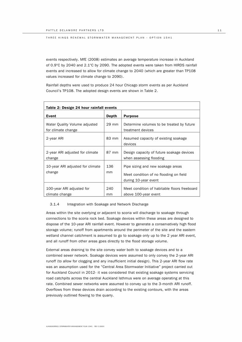
Rainfall depths were used to produce 24 hour Chicago storm events as per Auckland
Council’s TP108. The adopted design events are shown in Table 2.
Table 2: Design 24 hour rainfall events
Event Depth Purpose
Water Quality Volume adjusted
for climate change
29 mm Determine volumes to be treated by future
treatment devices
2-year ARI 83 mm Assumed capacity of existing soakage
devices
2-year ARI adjusted for climate
change
87 mm Design capacity of future soakage devices
when assessing flooding
10-year ARI adjusted for climate
change
136
mm
Pipe sizing and new soakage areas
Meet condition of no flooding on field
during 10-year event
100-year ARI adjusted for
climate change
240
mm
Meet condition of habitable floors freeboard
above 100-year event
3.1.4 Integration with Soakage and Network Discharge
Areas within the site overlying or adjacent to scoria will discharge to soakage through
connections to the scoria rock bed. Soakage devices within these areas are designed to
dispose of the 10-year ARI rainfall event. However to generate a conservatively high flood
storage volume; runoff from apartments around the perimeter of the site and the eastern
wetland channel catchment is assumed to go to soakage only up to the 2 year ARI event,
and all runoff from other areas goes directly to the flood storage volume.
External areas draining to the site convey water both to soakage devices and to a
combined sewer network. Soakage devices were assumed to only convey the 2-year ARI
runoff (to allow for clogging and any insufficient initial design). This 2-year ARI flow rate
was an assumption used for the “Central Area Stormwater Initiative” project carried out
for Auckland Council in 2012- it was considered that existing soakage systems servicing
road catchpits across the central Auckland Isthmus were on average operating at this
rate. Combined sewer networks were assumed to convey up to the 3-month ARI runoff.
Overflows from these devices drain according to the existing contours, with the areas
previously outlined flowing to the quarry.
P A T T L E D E L A M O R E P A R T N E R S L T D 1 2
T H R E E K I N G S R E N E W A L S T O R M W A T E R M A N A G E M E N T P L A N - O P T I O N 1 5 H 1
AJ456300R001 STORMWATER MANAGEMENT PLAN 15H1 - REV 3.DOCX
The 2-year soakage rate was also used within the development site to generate
conservative runoff volumes for identifying flood storage volumes within the site. However,
sediment loads to the site are expected to be lower than typical urban roads and
stormwater treatment will also be provided. As such, the actual discharge rate through
soakage devices on site is expected to be higher than predicted.
3.1.5 Model Results
The net runoff volume to flood storage (after allowing for the 2-year event to soakage in
selected areas) is approximately 31,000 m3 in the 100-year ARI rainfall event and
15,000 m3 in the 10-year ARI rainfall event.
Model results for individual sub-catchments are set out in Appendix B.
3.2 Groundwater Model
A simplified three-dimensional numerical groundwater model was constructed to estimate
the rise in the natural groundwater level (above RL 56.5 m) for non-pumping conditions
as a result of the 10- and 100-year ARI rainfall events. The modelling code selected for
this assessment was Visual Modflow version 4.6.0.162. The conceptual model and model
development are discussed in the following sections.
3.2.1 Conceptual Model
The conceptual model for the groundwater within and outside the cone is discussed
previously (PDP 2002 and 2008). The main elements of the conceptual model are
summarised below.
Geology
The geology in and around the Three Kings quarry can be divided into four main groups:
basalt, scoria, tuff, and non-extrusive sediments (Waitemata Group). Basalt, scoria and
some tuff dominate the quarry area and form a roughly circular outcrop defined by the
volcanic crater. The basalt can be found intercalated with, or intruded into, the scoria and
tuff forming a high elevation lava moat around the periphery of the crater. The main bulk
of tuff and non-extrusive sediments (principally Waitemata Group and younger Tauranga
Group) occur outside this area. The geological map is shown in Figure 6 (refer Appendix
A).
Groundwater Level
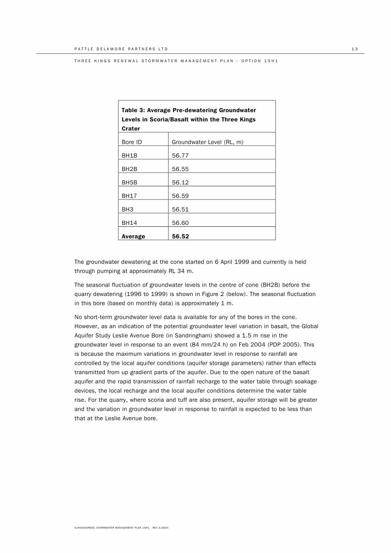
Pre-pumping water levels within the cone are around RL 56.5 m and are similar for all
bores within the cone. This is based on the average groundwater levels in the cone
(basalt and scoria) for the pre-dewatering conditions (1993-1999) as shown in Table 3.
P A T T L E D E L A M O R E P A R T N E R S L T D 1 3
T H R E E K I N G S R E N E W A L S T O R M W A T E R M A N A G E M E N T P L A N - O P T I O N 1 5 H 1
AJ456300R001 STORMWATER MANAGEMENT PLAN 15H1 - REV 3.DOCX
The groundwater dewatering at the cone started on 6 April 1999 and currently is held
through pumping at approximately RL 34 m.
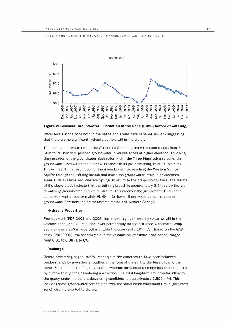
The seasonal fluctuation of groundwater levels in the centre of cone (BH2B) before the
quarry dewatering (1996 to 1999) is shown in Figure 2 (below). The seasonal fluctuation
in this bore (based on monthly data) is approximately 1 m.
No short-term groundwater level data is available for any of the bores in the cone.
However, as an indication of the potential groundwater level variation in basalt, the Global
Aquifer Study Leslie Avenue Bore (in Sandringham) showed a 1.5 m rise in the
groundwater level in response to an event (84 mm/24 h) on Feb 2004 (PDP 2005). This
is because the maximum variations in groundwater level in response to rainfall are
controlled by the local aquifer conditions (aquifer storage parameters) rather than effects
transmitted from up gradient parts of the aquifer. Due to the open nature of the basalt
aquifer and the rapid transmission of rainfall recharge to the water table through soakage
devices, the local recharge and the local aquifer conditions determine the water table
rise. For the quarry, where scoria and tuff are also present, aquifer storage will be greater
and the variation in groundwater level in response to rainfall is expected to be less than
that at the Leslie Avenue bore.
Table 3: Average Pre-dewatering Groundwater
Levels in Scoria/Basalt within the Three Kings
Crater
Bore ID Groundwater Level (RL, m)
BH1B 56.77
BH2B 56.55
BH5B 56.12
BH17 56.59
BH3 56.51
BH14 56.60
Average 56.52
P A T T L E D E L A M O R E P A R T N E R S L T D 1 4
T H R E E K I N G S R E N E W A L S T O R M W A T E R M A N A G E M E N T P L A N - O P T I O N 1 5 H 1
AJ456300R001 STORMWATER MANAGEMENT PLAN 15H1 - REV 3.DOCX
Figure 2: Seasonal Groundwater Fluctuation in the Cone (BH2B, before dewatering)
Water levels in the cone both in the basalt and scoria have behaved similarly suggesting
that there are no significant hydraulic barriers within the crater.
The main groundwater level in the Waitemata Group adjoining the cone ranges from RL
60m to RL 35m with perched groundwater in various zones at higher elevation. Following,
the cessation of the groundwater abstraction within the Three Kings volcanic cone, the
groundwater level within the crater will recover to its pre-dewatering level (RL 56.5 m).
This will result in a resumption of the groundwater flow reaching the Western Springs
Aquifer through the tuff ring breach and cause the groundwater levels in downstream
areas such as Meola and Western Springs to return to the pre-pumping levels. The results
of the above study indicate that the tuff ring breach is approximately 8.5m below the pre-
dewatering groundwater level of RL 56.5 m. This means if the groundwater level in the
cones was kept at approximately RL 48 m (or lower) there would be no increase in
groundwater flow from the crater towards Meola and Western Springs.
Hydraulic Properties
Previous work (PDP 2002 and 2008) has shown high permeability volcanics within the
volcanic cone (2 x 10⁻⁴ m/s) and lower permeability for the disturbed Waitemata Group
sediments in a 200 m wide collar outside the cone (9.4 x 10⁻⁷ m/s). Based on the GAS
study (PDP 2005), the specific yield in the volcanic aquifer (basalt and scoria) ranges
from 0.01 to 0.08 (1 to 8%).
Recharge
Before dewatering began, rainfall recharge to the crater would have been balanced
predominantly by groundwater outflow in the form of overspill to the basalt flow to the
north. Since the onset of steady-state dewatering the rainfall recharge has been balanced
by outflow through the dewatering abstraction. The total long-term groundwater inflow to
the quarry under the current dewatering conditions is approximately 2,500 m3/d. This
includes some groundwater contribution from the surrounding Waitemata Group (disturbed
zone) which is diverted to the pit.
56.0
56.5
57.0
57.5
58.0D
ec 1
996
Jan
1997
Feb
1997
Mar
199
7Ap
r 199
7M
ay 1
997
Jun
1997
Jul 1
997
Aug
1997
Sep
1997
Oct
199
7N
ov 1
997
Dec
199
7Ja
n 19
98Fe
b 19
98M
ar 1
998
Apr 1
998
May
199
8Ju
n 19
98Ju
l 199
8Au
g 19
98Se
p 19
98O
ct 1
998
Nov
199
8D
ec 1
998
Jan
1999
Feb
1999
Mar
199
9Ap
r 199
9
GW
Lev
el (
m, R
L)
Borehole 2B
P A T T L E D E L A M O R E P A R T N E R S L T D 1 5
T H R E E K I N G S R E N E W A L S T O R M W A T E R M A N A G E M E N T P L A N - O P T I O N 1 5 H 1
AJ456300R001 STORMWATER MANAGEMENT PLAN 15H1 - REV 3.DOCX
Recharge has been estimated previously to range from 120 mm/year (or approximately
10% of the annual rainfall) for the disturbed Waitemata Group to approximately 88% of
the rainfall for the volcanic cone.
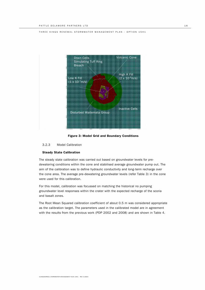
3.2.2 Model Set-up
System Geometry
The model domain contains the volcanic cone and about a 200 m zone of the disturbed
Waitemata Group with a uniform grid spacing of about 10 m and nine layers. The basalt
and scoria within the cone are simulated with a thickness of about 400 m. The layout is
shown in Figure 3 below.
Model Input Parameters
The model input parameters are based on the conceptual model discussed above. The
aquifer hydraulic properties represent average values over the whole saturated thickness
of the layer. The areas of different rates of infiltration during the rainfall event are shown
on Figure 7 (refer Appendix A). Area D has the highest infiltration rate, being the
remaining scoria cone. Areas E and F have low rates of infiltration as they are
predominately impervious. Areas A, B and C have moderate rates of infiltration as they
represent residential development with moderate amounts of imperviousness.
Boundary Conditions
“No flow boundaries” represent the boundary between active and inactive model cells
(across which there is no flow). This boundary was assigned outside the disturbed
Waitemata Group as any throughflow from the undisturbed Waitemata Group to the cone
is minor. The no flow boundary was also assigned to the north of the tuff ring breach.
The drain boundary was assigned to nodes located along the tuff ring breach between RL
56.5 and RL 48 m. The head along the drain cells was set at the pre-dewatering
groundwater level (RL 56.5 m). Drain cells remove water from the aquifer at a rate
proportional to the difference in heads between the aquifer and the water in the drain.
The drain cells are active only if the groundwater level in the cone is higher than the drain
elevation.
P A T T L E D E L A M O R E P A R T N E R S L T D 1 6
T H R E E K I N G S R E N E W A L S T O R M W A T E R M A N A G E M E N T P L A N - O P T I O N 1 5 H 1
AJ456300R001 STORMWATER MANAGEMENT PLAN 15H1 - REV 3.DOCX
Figure 3: Model Grid and Boundary Conditions
3.2.3 Model Calibration
Steady State Calibration
The steady state calibration was carried out based on groundwater levels for pre-
dewatering conditions within the cone and stabilised average groundwater pump out. The
aim of the calibration was to define hydraulic conductivity and long-term recharge over
the cone area. The average pre-dewatering groundwater levels (refer Table 3) in the cone
were used for this calibration.
For this model, calibration was focussed on matching the historical no pumping
groundwater level responses within the crater with the expected recharge of the scoria
and basalt zones.
The Root Mean Squared calibration coefficient of about 0.5 m was considered appropriate
as the calibration target. The parameters used in the calibrated model are in agreement
with the results from the previous work (PDP 2002 and 2008) and are shown in Table 4.
Low K Fill (1 x 10⁻⁷m/s)
Volcanic Cone
Disturbed Waitemata Group
Drain Cells Simulating Tuff Ring Breach
Inactive Cells
High K Fill (2 x 10⁻⁵m/s)
P A T T L E D E L A M O R E P A R T N E R S L T D 1 7
T H R E E K I N G S R E N E W A L S T O R M W A T E R M A N A G E M E N T P L A N - O P T I O N 1 5 H 1
AJ456300R001 STORMWATER MANAGEMENT PLAN 15H1 - REV 3.DOCX
Table 4: Steady State Calibrated Parameter
Parameters Basalt/Scoria Disturbed
Waitemata Group
Hydraulic
Conductivity (m/s)
2 x 10⁻⁴ 9.4 x 10⁻⁷ (1)
Recharge (mm/year) 1,000 (83% of
rainfall)
120 (10% of
rainfall)
1) Based on PDP (2008)
The calibrated water balance result is set out in Table 5. A less than 0.5% difference was
achieved between the average simulated and the observed groundwater discharge.
Table 5: Groundwater Mass Balance
Calculated
groundwater output
(through drain cells)
(m3/d)
Measured
groundwater pump-
out (m3/d)
2,509 2,500
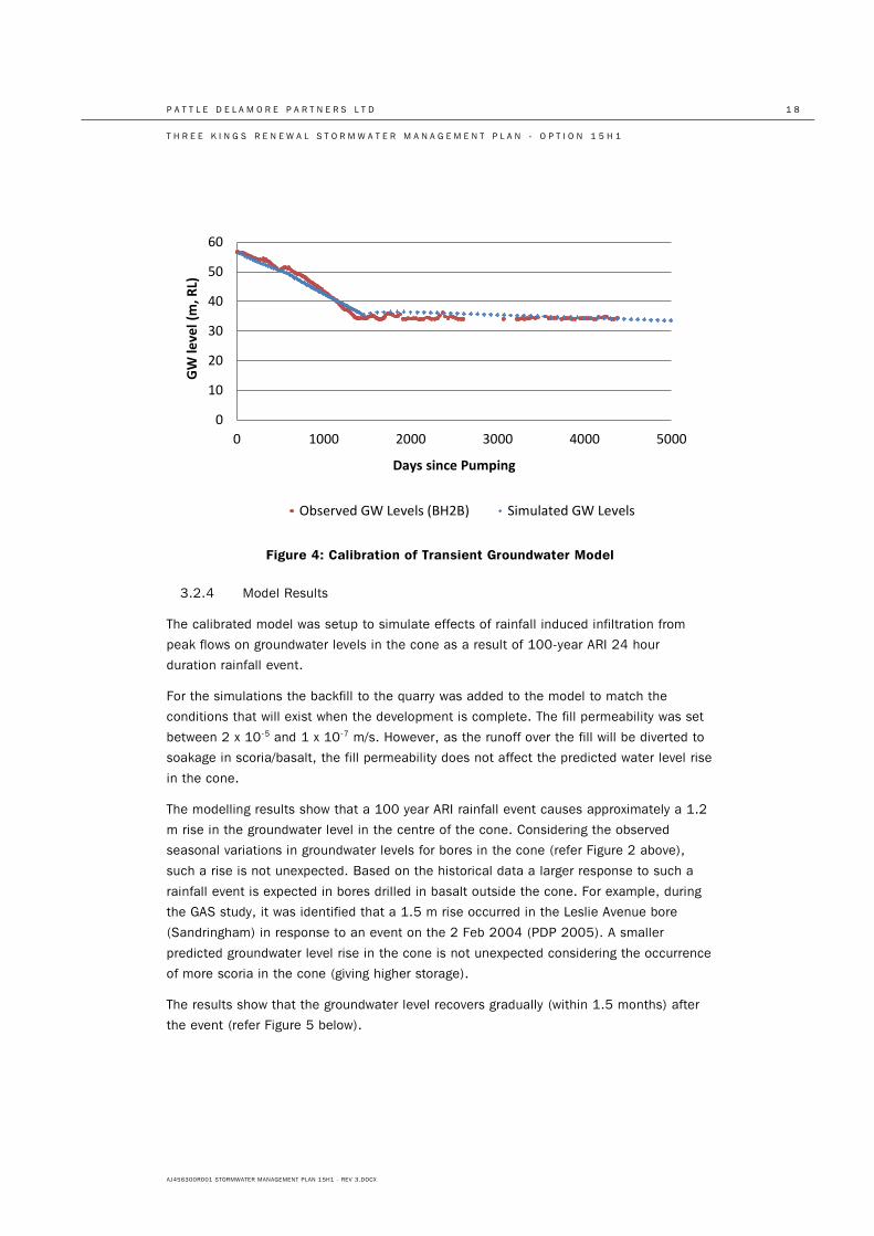
Transient Calibration
The transient calibration was undertaken to estimate the basalt storage parameters. The
observed groundwater level response to the pumping in the cone (BH2B) and average
pumping rates for about 13 years (from 1999) were used for this calibration. The average
pumping rate during this period was reduced from approximately 5000 to 2500 m3/d. The
storage coefficients were adjusted until the modelled groundwater fluctuations generally
matched the measured levels. The calibration result is given in Figure 4 (below).
The best calibration was achieved using the specific yield of 0.08. This is in agreement
with the upper range of the storage identified as part of the GAS study (0.01 to 0.08).
This calibration is currently being checked further through the direct measurement of
water levels in the quarry bore 2B in response to rainfall.
P A T T L E D E L A M O R E P A R T N E R S L T D 1 8
T H R E E K I N G S R E N E W A L S T O R M W A T E R M A N A G E M E N T P L A N - O P T I O N 1 5 H 1
AJ456300R001 STORMWATER MANAGEMENT PLAN 15H1 - REV 3.DOCX
Figure 4: Calibration of Transient Groundwater Model
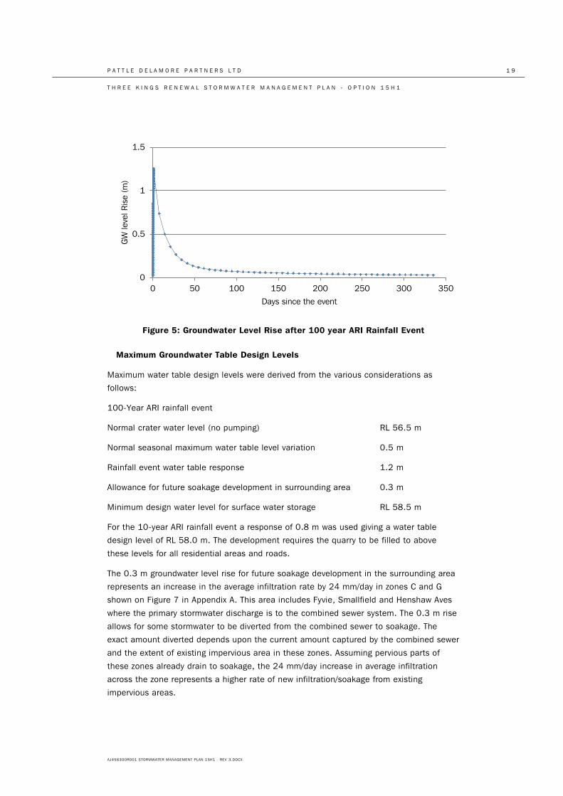
3.2.4 Model Results
The calibrated model was setup to simulate effects of rainfall induced infiltration from
peak flows on groundwater levels in the cone as a result of 100-year ARI 24 hour
duration rainfall event.
For the simulations the backfill to the quarry was added to the model to match the
conditions that will exist when the development is complete. The fill permeability was set
between 2 x 10⁻⁵ and 1 x 10⁻⁷ m/s. However, as the runoff over the fill will be diverted to
soakage in scoria/basalt, the fill permeability does not affect the predicted water level rise
in the cone.
The modelling results show that a 100 year ARI rainfall event causes approximately a 1.2
m rise in the groundwater level in the centre of the cone. Considering the observed
seasonal variations in groundwater levels for bores in the cone (refer Figure 2 above),
such a rise is not unexpected. Based on the historical data a larger response to such a
rainfall event is expected in bores drilled in basalt outside the cone. For example, during
the GAS study, it was identified that a 1.5 m rise occurred in the Leslie Avenue bore
(Sandringham) in response to an event on the 2 Feb 2004 (PDP 2005). A smaller
predicted groundwater level rise in the cone is not unexpected considering the occurrence
of more scoria in the cone (giving higher storage).
The results show that the groundwater level recovers gradually (within 1.5 months) after
the event (refer Figure 5 below).
0
10
20
30
40
50
60
0 1000 2000 3000 4000 5000
GW
leve
l (m
, RL)
Days since Pumping
Observed GW Levels (BH2B) Simulated GW Levels
P A T T L E D E L A M O R E P A R T N E R S L T D 1 9
T H R E E K I N G S R E N E W A L S T O R M W A T E R M A N A G E M E N T P L A N - O P T I O N 1 5 H 1
AJ456300R001 STORMWATER MANAGEMENT PLAN 15H1 - REV 3.DOCX
Figure 5: Groundwater Level Rise after 100 year ARI Rainfall Event
Maximum Groundwater Table Design Levels
Maximum water table design levels were derived from the various considerations as
follows:
100-Year ARI rainfall event
Normal crater water level (no pumping) RL 56.5 m
Normal seasonal maximum water table level variation 0.5 m
Rainfall event water table response 1.2 m
Allowance for future soakage development in surrounding area 0.3 m
Minimum design water level for surface water storage RL 58.5 m
For the 10-year ARI rainfall event a response of 0.8 m was used giving a water table
design level of RL 58.0 m. The development requires the quarry to be filled to above
these levels for all residential areas and roads.
The 0.3 m groundwater level rise for future soakage development in the surrounding area
represents an increase in the average infiltration rate by 24 mm/day in zones C and G
shown on Figure 7 in Appendix A. This area includes Fyvie, Smallfield and Henshaw Aves
where the primary stormwater discharge is to the combined sewer system. The 0.3 m rise
allows for some stormwater to be diverted from the combined sewer to soakage. The
exact amount diverted depends upon the current amount captured by the combined sewer
and the extent of existing impervious area in these zones. Assuming pervious parts of
these zones already drain to soakage, the 24 mm/day increase in average infiltration
across the zone represents a higher rate of new infiltration/soakage from existing
impervious areas.
0
0.5
1
1.5
0 50 100 150 200 250 300 350
GW
leve
l Ris
e (m
)
Days since the event
P A T T L E D E L A M O R E P A R T N E R S L T D 2 0
T H R E E K I N G S R E N E W A L S T O R M W A T E R M A N A G E M E N T P L A N - O P T I O N 1 5 H 1
AJ456300R001 STORMWATER MANAGEMENT PLAN 15H1 - REV 3.DOCX
4.0 Design Considerations
4.1 General
A number of design considerations and constraints directed the stormwater management
plan. The design parameters are closely related and result in an iterative process of
determining an appropriate stormwater management plan. These included:
• Building floor levels and freeboard to flood levels;
• Grades and water levels for primary and secondary drainage systems;
• Flood levels;
• Likely depths for other services;
• Road levels and geometry;
• Location and volume of flood storage zones;
• Stormwater quality treatment devices locations and geometry; • Soakage discharge points.
General Requirements
The Proposed Auckland Unitary Plan (PAUP), in Section 4.12 3.1, identifies the following
matters of discretion when processing consents related to flooding:
a. design of the structure, works or infrastructure
b. extent of any earthworks proposed
c. construction methodology
d. potential impacts on overland flow paths including:
i. obstruction of flows
ii. any change to location and capacity
iii. any change to overland flow on other properties.
e. provision of secondary flow paths
f. effects on existing infrastructure
g. potential changes in flood depth and frequency upstream and downstream of
the site and potential flooding of habitable floors
h. provision of site access and potential effects of chosen access route
i. ongoing access, maintenance and reporting requirements
j. methods of providing for long term maintenance and protection such as
easements
P A T T L E D E L A M O R E P A R T N E R S L T D 2 1
T H R E E K I N G S R E N E W A L S T O R M W A T E R M A N A G E M E N T P L A N - O P T I O N 1 5 H 1
AJ456300R001 STORMWATER MANAGEMENT PLAN 15H1 - REV 3.DOCX
4.2 Design Standards
Hydrology
Surface water hydrology has been assessed generally in accordance with Auckland
Council TP 108 as described in Section 3.1.
The Auckland Council Code of Practice for Land Development and Subdivision, Oct 2013,
Part 4, Stormwater, Section 4.3.5.1 requires estimation of surface water run-off shall be
carried out in accordance with TP108.
Groundwater hydrology has been assessed as described in Section 3.2.
Consideration of Climate Change
The potential effects of climate change have been factored into the stormwater designs.
The assessment was carried out in accordance with MfE document “Preparing for Climate
Change” (2008).
Reticulating the 10 year ARI Rainfall Event
A combination of soakage and stormwater reticulation on the site will dispose of the 10-
year ARI rainfall event to groundwater or storage without generation of overland flows.
The Building Code, Performance Standard E1.3.1 requires the effects of stormwater on
other property to be managed up to a 10% probability event.
The Auckland Council Code of Practice for Land Development and Subdivision, Oct 2013,
Part 4, Stormwater, Section 4.3.5.2 requires primary drainage systems be designed for
the 10% AEP event. Note that the 10% AEP event and the 10-year ARI event are
considered equivalent.
Providing Overland Flow Paths for the 100-Year Event
Up to the 100-year ARI rainfall event, overland flow paths should be provided which
convey stormwater with a minimum of nuisance.
The Auckland Regional Plan: Air, Land, Water controlled activity Rule 5.5.2 includes a
requirement for overland flow paths to be provided and discharge with a minimum of
nuisance and damage up to the 100-year ARI rainfall event.
The Auckland Council Code of Practice for Land Development and Subdivision, Oct 2013,
Part 4, Stormwater, Sections 4.3.4.2 and 4.3.5.2 requires a secondary drainage system,
consisting of ponding areas and overland flow paths, be designed for the 1% AEP event.
Providing Underground Flood Storage for the 10-Year Event
The 10 year ARI runoff volume should be stored sufficiently so that there is no surface
flooding on the sports field during the 10-year event. Fletcher Residential Ltd requires this
to ensure only very occasional interruption to the use of the sports field. Auckland
P A T T L E D E L A M O R E P A R T N E R S L T D 2 2
T H R E E K I N G S R E N E W A L S T O R M W A T E R M A N A G E M E N T P L A N - O P T I O N 1 5 H 1
AJ456300R001 STORMWATER MANAGEMENT PLAN 15H1 - REV 3.DOCX
Council have advised that they support in principle the use of public spaces such as parks
and carparks for flood attenuation for events greater than 10 years.
Providing Flood Freeboard for the 100 Year Event
Storage should be provided to ensure that appropriate freeboard is provided to habitable
floors during the 100-year ARI event.
The PAUP gives permitted activity status to “vulnerable activities in flood sensitive areas”
that have 500 mm freeboard above the 1% AEP flood level (Part 3: Chapter H, Section
4.12 (2.1.1) (1)). The Auckland Council Code of Practice has the same requirement. The
Auckland Regional Plan: Air, Land, Water controlled activity Rule 5.5.2 includes a
requirement for 500 mm freeboard between the 100 year ARI flood level and habitable
building floor levels.
Notwithstanding this, the design has been developed with a higher standard of freeboard
– namely floor levels are set above a hypothetical flood level assuming there is no short
term soakage occurring and allowing for the entire 100-year ARI rainfall depth (i.e. not
just runoff) to be stored. This means floor levels are at least 750 mm above the 100-year
ARI flood levels identified for flood storage areas A, B, C.
Providing for Ultimate Disposal of Stored Stormwater
Stormwater which is stored during and after rainfall events should be eventually
discharged via soakage or another means.
The fractured basalt and scoria which makes up part of the quarry walls and floor provides
capacity to discharge surface water to ground via soakage. This is an effective and
desirable means of stormwater discharge as it reduces storage requirements and peak
flows within the development. It also contributes to recharge of the local aquifer. Soakage
should be utilised to the fullest extent practical.
Face mapping of the quarry walls (refer Tonkin & Taylor Figure 2 in Appendix A) has
identified scoria areas where it is proposed to discharge via soakage. These are: generally
around the perimeter road in between apartment blocks, the scoria pit in the south
western corner of the quarry (pond A is to be placed above this) and a “peninsula” of
scoria extending beneath the sports field from the south.
Tonkin & Taylor Ltd are monitoring the placement of fill material within the quarry and
they have provided soil void ratios to be used for calculating underground flood storage.
They have advised that no underground flood storage should be assumed within one
metre depth of the surface to allow for road construction and compacted fill/landscaping
over the sports field and residential areas. Within one to two metres depth, they have
advised that a graded filter material be placed with a void ratio of 15 to 20% and below
this the bulk fill can be assumed to have a void ratio of 25%.
P A T T L E D E L A M O R E P A R T N E R S L T D 2 3
T H R E E K I N G S R E N E W A L S T O R M W A T E R M A N A G E M E N T P L A N - O P T I O N 1 5 H 1
AJ456300R001 STORMWATER MANAGEMENT PLAN 15H1 - REV 3.DOCX
Water Quality Treatment
All contaminant generating surfaces such as roads and roofs should discharge to a water
quality treatment train prior to ultimate disposal of stormwater. These treatment trains
should be integrated into public amenities such as gardens and wetlands to maximise use
of available space.
The Auckland Regional Plan: Air, Land, Water controlled activity Rule 5.5.2 includes a
requirement for removal of 75% total suspended solids from any new impervious surface
greater than 1000 m2. The PAUP has a range of stormwater quality provisions under Part
3, Chapter H, Section 4.14 (3).
Sizing the treatment devices will be consistent with the former Auckland Council’s TP10
as required by the Auckland Council Code of Practice for Land Development and
Subdivision, Oct 2013, Part 4, Stormwater, Section 4.3.6.1.
We understand Fletcher Residential Ltd has worked closely with iwi to ensure that this
element of the proposal will deliver a sustainable long term solution.
P A T T L E D E L A M O R E P A R T N E R S L T D 2 4
T H R E E K I N G S R E N E W A L S T O R M W A T E R M A N A G E M E N T P L A N - O P T I O N 1 5 H 1
AJ456300R001 STORMWATER MANAGEMENT PLAN 15H1 - REV 3.DOCX
4.3 Options Analysis
A qualitative assessment of options for the stormwater management approach is provided
in Appendix D.
The matrix of the options in Appendix D shows that all options have common stormwater
infrastructure requirements such as an internal stormwater pipe system and stormwater
quality treatment. All options also require some form of flood storage on site – either
because the proposed development levels are below the surrounding area’s ground levels
or because flow detention is required to avoid effects on downstream pipe systems and
flood prone areas. Therefore these are assumed to be generally similar in terms of cost.
Options where the quarry is filled to the surrounding ground levels incur additional cost
and time to obtain fill and reduced revenue from a reduced development yield. These
have therefore been discounted.
Of the options where the development is constructed at levels of approximately RL 59m to
65m, the tunnel option incurs significantly greater cost in terms of tunnel construction.
Furthermore significant flow detention and possibly also downstream pipe upgrades are
expected indicating additional cost and practicality issues. This has therefore been
discounted. The two soakage options are considered broadly similar in terms of
stormwater capital cost - however the pumping option introduces ongoing operational
cost. A soakage system can be designed without pumping being required and this is
considered preferable in terms of long term robustness and certainty. Soakage systems
receiving high sediment loads are susceptible to blockage. However in this case, long
term sediment loads are expected to be relatively low as they are from residential
development and stormwater treatment will manage the loads generated.
Iwi have identified that they prefer the discharge to be to the Meola catchment. This
means that they prefer a discharge to soakage without on-going pumping.
The “soakage without ongoing pumping” option avoids potential effects on existing
flooding areas off-site and is considered to a practical solution for stormwater
management on site. This option is therefore used as the basis for the development.
P A T T L E D E L A M O R E P A R T N E R S L T D 2 5
T H R E E K I N G S R E N E W A L S T O R M W A T E R M A N A G E M E N T P L A N - O P T I O N 1 5 H 1
AJ456300R001 STORMWATER MANAGEMENT PLAN 15H1 - REV 3.DOCX
5.0 Proposed Stormwater Management
5.1 Design Summary
Stormwater runoff within the Three Kings Renewal project will be managed through a
combination of soakage, reticulated networks, stormwater treatment and overland flow.
Treatment will include sedimentation ponds, a wetland channel with four cells on the
eastern side of the site, swales and rain-gardens. Surface water which does not infiltrate
and is not directly discharged to soakage will be conveyed to soakage areas adjacent to
the wetland and three main storage areas toward the south of the site. Pond A utilises
both below and above ground storage. Sports field B and Area C uses below ground
stormwater storage under the adjacent roads and will provide additional above ground
storage during greater events. Additional sites for underground storage will be provided by
large soakage chambers adjacent / under the eastern wetland channel and at soakage
areas for individual apartment blocks.
The two most limiting design features for storage are the upper and lower elevation limits
available for water. The lower limit for the 10- and 100-year ARI rainfall events are the
respective groundwater levels. The upper limit for storing the 10-year ARI rainfall event is
the surface of the field (accounting for freeboard) and the upper limit for the 100-year
ARI rainfall event is determined from the freeboard for habitable floor levels.
It is desirable to have the floor levels as low as feasible so that the maximum space is
available for apartment blocks; however these must have adequate freeboard above the
100-year ARI flood level. It is also desirable to have the sports field as low as possible
(while maintaining field serviceability up to the 10 year event), as surface flooding
provides a significant amount of storage for the 100-year ARI rainfall event. Finally,
development areas need to be suitably drained to provide competent foundations under
roads and buildings – underground storage is therefore not contemplated within 1m of the
ground surface and only limited storage within a graded filter material is provided between
1 and 2m depth below ground level. Soakage areas, underground storage, ponds,
wetlands and the field level were iteratively adjusted to optimise these parameters.
The 10-year groundwater level was calculated as RL 58.0 m. The field level was originally
specified at RL 58 m in Option 15D, however this leaves no storage depth or room for the
field foundations. For this reason, the field was raised to RL 59 m, allowing for the
foundation layer and up to 1m of storage in the adjacent areas under the perimeter road.
The short term groundwater level in response to the 100-year ARI rainfall event was
calculated as RL 58.5 m. As such, roads around the field were set to a minimum of RL
60 m, allowing for up to 1.5 m of storage in Pond A, and up to 1 m of storage on the
surface of the sports field and Area C. Habitable floor zones must be above the 100-year
flood level (as well as any overland flow paths). As stormwater pipes are only designed up
to the 10-year event, the excess will be conveyed through overland flow on the road. For
this reason, habitable floors must also have freeboard above the water level in adjacent
overland major flow paths (down the roads).
P A T T L E D E L A M O R E P A R T N E R S L T D 2 6
T H R E E K I N G S R E N E W A L S T O R M W A T E R M A N A G E M E N T P L A N - O P T I O N 1 5 H 1
AJ456300R001 STORMWATER MANAGEMENT PLAN 15H1 - REV 3.DOCX
Soakage capacity is available at a number of locations within the development, primarily
where a connection to the scoria cliffs or underlying scoria rock are available. Soakage
adjacent/below the eastern wetland cells and flood storage areas A, B, C will provide
drainage for the majority of the site. Soakage pits will be separately provided for individual
apartment blocks in the west.
The overall Stormwater Management Concept is shown on Figure 9 (refer Appendix A).
5.2 Main Development System
5.2.1 Flow Paths and Reticulated Network
Flow enters the quarry from a number of off-site catchments identified on Figure 8 (refer
Appendix A). These contributions will be collected via reticulation or overland flow paths.
A reticulated network will be provided to convey stormwater from the central part of the
development towards the east into a wetland channel and flood storage areas A, B and C
in the south.
Areas around the sports field will be either reticulated to Pond A and cell 4 of the eastern
wetland channel and then into flood storage, or, reticulated to rain-gardens around the
perimeter of the sports field and then into flood storage.
5.2.2 Flooding
Flood Storage
The total runoff from the 100-year ARI rainfall event is approximately 31,000 m3, to be
stored within the site. Above and underground storage volumes at Pond A, Sports field B
and Area C are approximately 3,500 m3, 18,000 m3 and 4,000 m3 respectively, for a
total of 25,500 m3. Additional storage chambers have therefore been included, and
storage of the 10-year and 100-year runoff volumes therefore comprises of:
• Surface storage on Pond A, Sports field B and Area C;
• Underground storage around Pond A and under roads adjacent to Sports field B
and Area C;
• Underground storage in the soakage chambers adjacent to and under the
wetland cells; and
• Underground storage in the western soakage chambers (for the individual
apartment blocks – refer section 5.3).
All other storage areas (such as surface storage in the wetland and conveyance devices)
are assumed negligible.
Surface storage in Pond A, the Sports field and Area C is provided over the storage areas
indicated in Figure 11 (refer Appendix A). Pond A is assumed to hold some permanent
water; it is assumed it fills up due to short term groundwater rise. Above RL 58.0 m and
58.5 for the 10-year and 100-year rainfall events respectively, the pond can provide
P A T T L E D E L A M O R E P A R T N E R S L T D 2 7
T H R E E K I N G S R E N E W A L S T O R M W A T E R M A N A G E M E N T P L A N - O P T I O N 1 5 H 1
AJ456300R001 STORMWATER MANAGEMENT PLAN 15H1 - REV 3.DOCX
surface storage. The sports field and Area C holds surface water above its surface, RL 59
m. It holds no surface water in the 10-year ARI rainfall event. Note there is no physical
barrier between the sports field and Area C flood storages.
Underground storage is provided in the void spaces in the construction fill adjacent to
Pond A, below the roads adjacent to the sports field and Area C as shown in Figure 11.
This is necessary to ensure that no flooding occurs on the sports field in the 10 year ARI
rainfall event. The areas are hydraulically connected to ensure a constant level across the
fill media. Tonkin and Taylor advised that a void ratio of 25% can be reliably achieved for
this storage material. A 1m layer (with no storage) is included below all surfaces for
foundation purposes with a further 1m graded fill layer required under residential areas
and roads. Tonkin and Taylor specify that this graded fill will have a storage capacity of
approximately 15% to 20%. These underground fill areas are hydraulically connected to
the surface storages in Pond A, Sports field B and Area C, and therefore maintain a
constant level while filling.
Underground storage is also provided in the soakage chambers adjacent/under the
eastern wetland cells (also shown on Figure 11). Soakage is provided below and adjacent
to the wetland channel for events up to the 10-year runoff volume, with the chambers
also functioning as storage devices. Similarly, underground storage and soakage is
provided in two south-western soakage areas for apartments off Grahame Breed Drive and
four soakage areas servicing western apartments. These provide storage and soakage for
runoff from residential areas and roads draining to them, reducing the storage
requirements downstream. These soakage areas are not hydraulically connected to the
sports fields or other soakage devices, and therefore are able to fill above RL 59m and RL
60m for the 10-year and 100-year rainfall events where available.
The storage available for 10-year and 100-year runoff volumes could be determined from
a storage-elevation curve. The total storage available to RL 59 m and RL 60 m for the 10-
year and 100-year volumes is shown in Table 6. The following points are noted:
• Underground storage at areas A, B and C is less for the 100-year runoff volumes
than the 10-year due to the increased groundwater level in the 100-year event.
• Approximately 60% of the 100-year event is managed by surface storage at
areas A, B, and C; approximately 75% of this storage is from flooding the sports
field.
• Soakage chambers elsewhere in the development are designed to hold up to the
10-year runoff volume only. It is convservatively assumed that they provide no
additional storage/soakage in the 100-year event. In practice, the chambers
would be full for a greater duration of the storm, and therefore provide increased
soakage.
• Storage values provided in the soakage chambers conservatively do not account
for losses during the storm to soakage. However, runoff values from apartments
managed by soakage have already accounted for the soakage reduction.
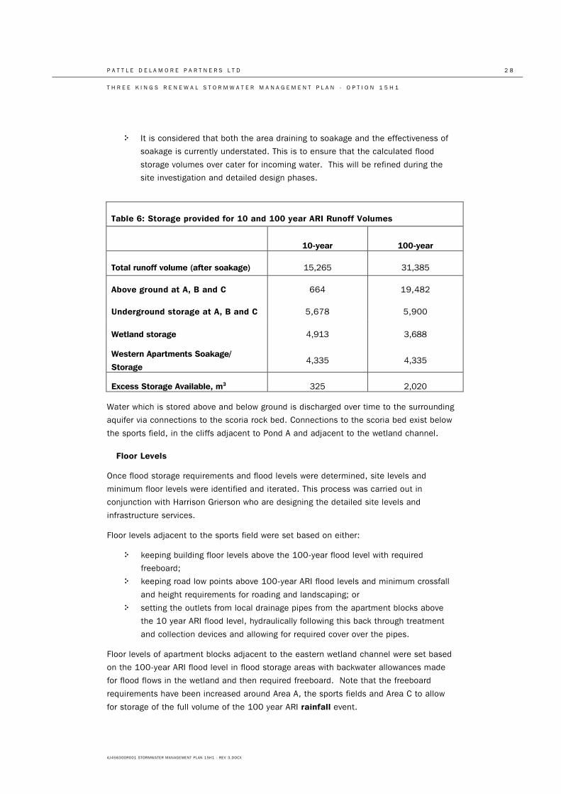
P A T T L E D E L A M O R E P A R T N E R S L T D 2 8
T H R E E K I N G S R E N E W A L S T O R M W A T E R M A N A G E M E N T P L A N - O P T I O N 1 5 H 1
AJ456300R001 STORMWATER MANAGEMENT PLAN 15H1 - REV 3.DOCX
• It is considered that both the area draining to soakage and the effectiveness of
soakage is currently understated. This is to ensure that the calculated flood
storage volumes over cater for incoming water. This will be refined during the
site investigation and detailed design phases.
Table 6: Storage provided for 10 and 100 year ARI Runoff Volumes
10-year 100-year
Total runoff volume (after soakage) 15,265 31,385
Above ground at A, B and C 664 19,482
Underground storage at A, B and C 5,678 5,900
Wetland storage 4,913 3,688
Western Apartments Soakage/
Storage 4,335 4,335
Excess Storage Available, m3 325 2,020
Water which is stored above and below ground is discharged over time to the surrounding
aquifer via connections to the scoria rock bed. Connections to the scoria bed exist below
the sports field, in the cliffs adjacent to Pond A and adjacent to the wetland channel.
Floor Levels
Once flood storage requirements and flood levels were determined, site levels and
minimum floor levels were identified and iterated. This process was carried out in
conjunction with Harrison Grierson who are designing the detailed site levels and
infrastructure services.
Floor levels adjacent to the sports field were set based on either:
• keeping building floor levels above the 100-year flood level with required
freeboard;
• keeping road low points above 100-year ARI flood levels and minimum crossfall
and height requirements for roading and landscaping; or
• setting the outlets from local drainage pipes from the apartment blocks above
the 10 year ARI flood level, hydraulically following this back through treatment
and collection devices and allowing for required cover over the pipes.
Floor levels of apartment blocks adjacent to the eastern wetland channel were set based
on the 100-year ARI flood level in flood storage areas with backwater allowances made
for flood flows in the wetland and then required freeboard. Note that the freeboard
requirements have been increased around Area A, the sports fields and Area C to allow
for storage of the full volume of the 100 year ARI rainfall event.
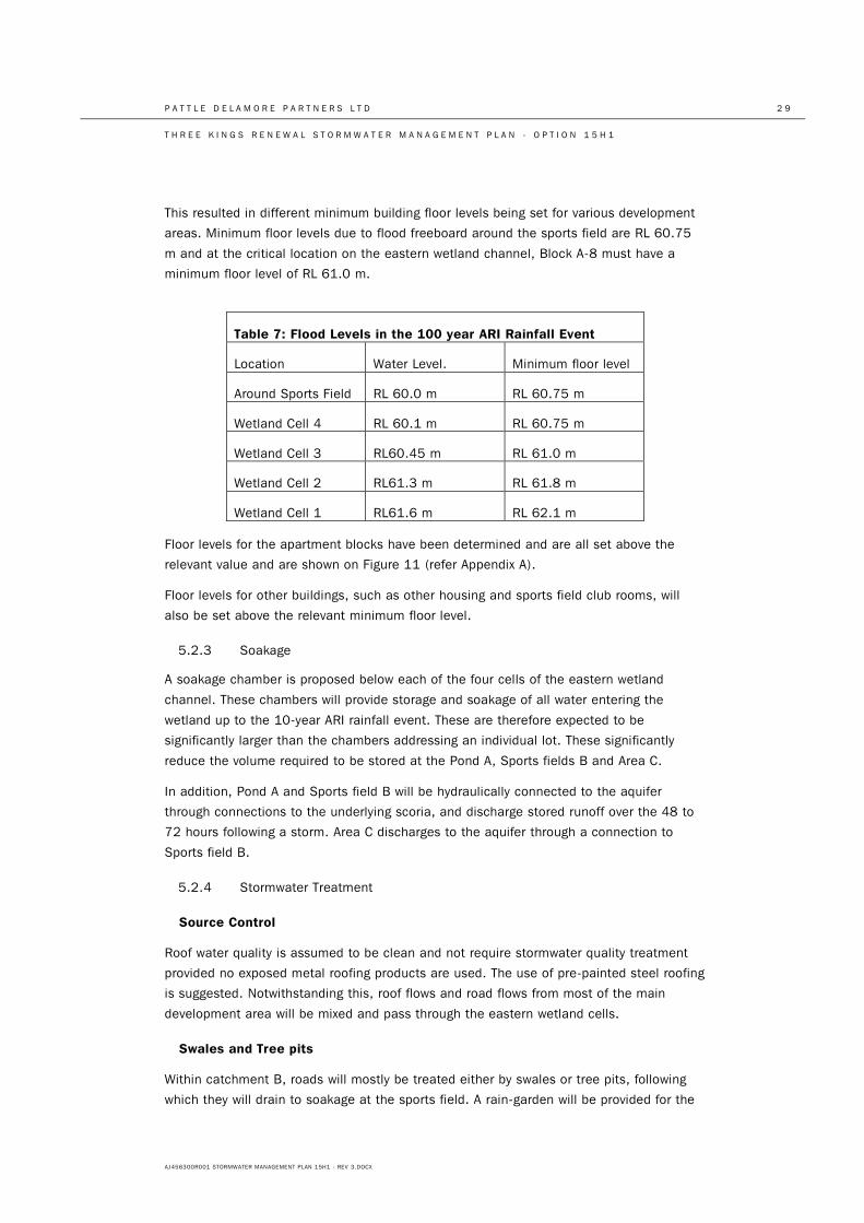
P A T T L E D E L A M O R E P A R T N E R S L T D 2 9
T H R E E K I N G S R E N E W A L S T O R M W A T E R M A N A G E M E N T P L A N - O P T I O N 1 5 H 1
AJ456300R001 STORMWATER MANAGEMENT PLAN 15H1 - REV 3.DOCX
This resulted in different minimum building floor levels being set for various development
areas. Minimum floor levels due to flood freeboard around the sports field are RL 60.75
m and at the critical location on the eastern wetland channel, Block A-8 must have a
minimum floor level of RL 61.0 m.
Table 7: Flood Levels in the 100 year ARI Rainfall Event
Location Water Level. Minimum floor level
Around Sports Field RL 60.0 m RL 60.75 m
Wetland Cell 4 RL 60.1 m RL 60.75 m
Wetland Cell 3 RL60.45 m RL 61.0 m
Wetland Cell 2 RL61.3 m RL 61.8 m
Wetland Cell 1 RL61.6 m RL 62.1 m
Floor levels for the apartment blocks have been determined and are all set above the
relevant value and are shown on Figure 11 (refer Appendix A).
Floor levels for other buildings, such as other housing and sports field club rooms, will
also be set above the relevant minimum floor level.
5.2.3 Soakage
A soakage chamber is proposed below each of the four cells of the eastern wetland
channel. These chambers will provide storage and soakage of all water entering the
wetland up to the 10-year ARI rainfall event. These are therefore expected to be
significantly larger than the chambers addressing an individual lot. These significantly
reduce the volume required to be stored at the Pond A, Sports fields B and Area C.
In addition, Pond A and Sports field B will be hydraulically connected to the aquifer
through connections to the underlying scoria, and discharge stored runoff over the 48 to
72 hours following a storm. Area C discharges to the aquifer through a connection to
Sports field B.
5.2.4 Stormwater Treatment
Source Control
Roof water quality is assumed to be clean and not require stormwater quality treatment
provided no exposed metal roofing products are used. The use of pre-painted steel roofing
is suggested. Notwithstanding this, roof flows and road flows from most of the main
development area will be mixed and pass through the eastern wetland cells.
Swales and Tree pits
Within catchment B, roads will mostly be treated either by swales or tree pits, following
which they will drain to soakage at the sports field. A rain-garden will be provided for the
P A T T L E D E L A M O R E P A R T N E R S L T D 3 0
T H R E E K I N G S R E N E W A L S T O R M W A T E R M A N A G E M E N T P L A N - O P T I O N 1 5 H 1
AJ456300R001 STORMWATER MANAGEMENT PLAN 15H1 - REV 3.DOCX
service lane within Super Lot C. There are opportunities for swales or tree-pits for roads
in catchments A and C also (which are shown on Figure 9H1 in Appendix A), however
these are not required in addition to treatment provided by the eastern wetland and Pond
A.
Tree pits will be formed by a local depression below footpath or ground level with a
diversion of roadside water via a kerb cut into the depression. Soakage will be free to
occur through the base of the tree pit media – no box chamber is proposed to contain
and collect flow.
Sedimentation Basins
For flows draining to Pond A or the wetland channel within catchment C, primary
treatment will be provided by sedimentation basins designed to remove coarse sediments.
These will be sized to operate as sediment forebays and will therefore be sized at
approximately 15% of the water quality volume as set out in TP10.
Flows from the upper sections of the entry road from Mt Eden Road will be treated by a
sedimentation chamber, following which they will discharge to soakage. The lower section
of this road will drain to the wetland channel.
Pond A
Pond A will be sized to provide treatment for Grahame Breed Drive.
Sediment forebays will provide initial treatment for flow entering the pond. Wetland
vegetation will be established within and around the pond. Water will discharge to a
soakage area under the pond.
Underground flood storage is provided in the areas adjacent to the pond. This will be fed
from water which has firstly passed through the pond and a filter media to remove
sediment.
Wetland Channel
The eastern wetland channel will have a permanent water level which provides storage for
the water quality volume for the contributing catchment. The water quality volume for the
wetland catchment is 1032 m3 and the available permanent volume within the wetland is
at least 1640 m3.
4,875 m³ of subsurface storage will be provided adjacent/below the wetland channel to
make up the total flood storage volume required. Flow to the flood storage and soakage
areas will be fed from water which has firstly passed through the wetland and a filter
media to remove sediment. Flow from the wetland cells will preferentially be discharged to
soakage areas along the eastern quarry face. Flows in excess of soakage capacity at
these points will flow south to flood storage areas A, B, C.
In dry periods open water will be present in the main channel sections and any margin
sections that do not also operate as soakage areas. To maintain permanent water levels
within the wetland cells it may be necessary to line the wetland cells. A small constant
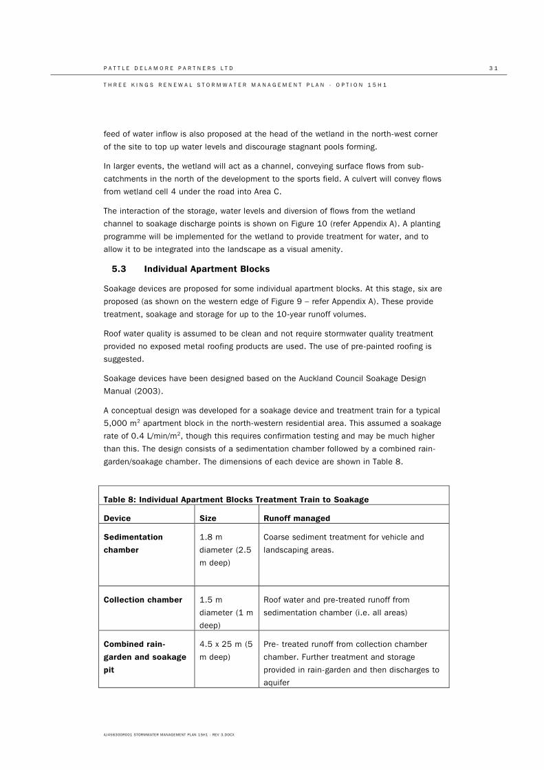
P A T T L E D E L A M O R E P A R T N E R S L T D 3 1
T H R E E K I N G S R E N E W A L S T O R M W A T E R M A N A G E M E N T P L A N - O P T I O N 1 5 H 1
AJ456300R001 STORMWATER MANAGEMENT PLAN 15H1 - REV 3.DOCX
feed of water inflow is also proposed at the head of the wetland in the north-west corner
of the site to top up water levels and discourage stagnant pools forming.
In larger events, the wetland will act as a channel, conveying surface flows from sub-
catchments in the north of the development to the sports field. A culvert will convey flows
from wetland cell 4 under the road into Area C.
The interaction of the storage, water levels and diversion of flows from the wetland
channel to soakage discharge points is shown on Figure 10 (refer Appendix A). A planting
programme will be implemented for the wetland to provide treatment for water, and to
allow it to be integrated into the landscape as a visual amenity.
5.3 Individual Apartment Blocks
Soakage devices are proposed for some individual apartment blocks. At this stage, six are
proposed (as shown on the western edge of Figure 9 – refer Appendix A). These provide
treatment, soakage and storage for up to the 10-year runoff volumes.
Roof water quality is assumed to be clean and not require stormwater quality treatment
provided no exposed metal roofing products are used. The use of pre-painted roofing is
suggested.
Soakage devices have been designed based on the Auckland Council Soakage Design
Manual (2003).
A conceptual design was developed for a soakage device and treatment train for a typical
5,000 m2 apartment block in the north-western residential area. This assumed a soakage
rate of 0.4 L/min/m2, though this requires confirmation testing and may be much higher
than this. The design consists of a sedimentation chamber followed by a combined rain-
garden/soakage chamber. The dimensions of each device are shown in Table 8.
Table 8: Individual Apartment Blocks Treatment Train to Soakage
Device Size Runoff managed
Sedimentation
chamber
1.8 m
diameter (2.5
m deep)
Coarse sediment treatment for vehicle and
landscaping areas.
Collection chamber 1.5 m
diameter (1 m
deep)
Roof water and pre-treated runoff from
sedimentation chamber (i.e. all areas)
Combined rain-
garden and soakage
pit
4.5 x 25 m (5
m deep)
Pre- treated runoff from collection chamber
chamber. Further treatment and storage
provided in rain-garden and then discharges to
aquifer
P A T T L E D E L A M O R E P A R T N E R S L T D 3 2
T H R E E K I N G S R E N E W A L S T O R M W A T E R M A N A G E M E N T P L A N - O P T I O N 1 5 H 1
AJ456300R001 STORMWATER MANAGEMENT PLAN 15H1 - REV 3.DOCX
This design is based on a conservative estimate of soakage rates, and demonstrates
feasibility to service up to the 10-year rainfall event while providing water quality
treatment. It is noted that the volume of the soakage chamber could be reduced if the
soakage capacity is found to be greater than assumed.
It will be necessary to test and confirm soakage rates at the proposed discharge location
prior to detailed design being carried out.
5.4 Multiple Flood Events
Surface water runoff stored on site in the flood storage areas will drain via soakage into
the groundwater table. This is in addition to the rise in groundwater level due to
infiltration (calculated in the section on groundwater modelling). Drainage of the flood
storage volume will be governed by a combination of; the rate of the receding short term
rise in groundwater level, lateral dissipation of water to fill up rock void space in the
underground basin, and (depending upon the rate of the first two mechanisms) additional
surface water storage.
The groundwater model shows that the short term ground water level rise will fall by 0.75
m in the first 7 days (refer Figure 5). The model is to be re-calibrated and the rate of
recession recalculated following the current monitoring of the short term groundwater
level response to rainfall events.
The volume of underground storage within the 1000 m diameter Three Kings volcanic
crater is approximately 62,000 m3 per vertical m assuming an average 8% voids in the
volcanic materials. This volume is conservative as while 8% is appropriate for basalt the
void ratio of the scoria layers present will be 30 to 50%.
The runoff volume in the 100-year event stored in above ground storage is 25,500 m3.
Connections from the above ground stored runoff volume to soakage will need to be
engineered to allow this stored runoff volume to soak away quickly enough to make space
for a potential subsequent rainfall event.
The potential rise in groundwater level following the rainfall event is assessed as:
• Design short term groundwater level in 100-year rainfall event = RL 58.5 m
• Groundwater level rise due to soakage of stored runoff = 0.41 m (25,500 m3 /
62,000 m3)
• Fall in short term groundwater level after 24 hours = 0.10 m (0.75 m / 7 days)
• Potential ground water level 24 hours after the rainfall event: RL 58.81 m
If soakage into the surrounding rock was not quick enough, there would still be water in
the flood storage areas A, B, C during a second extreme rainfall event. In this case, a
conservative check on potential flooding is to add a second 100 year ARI runoff volume
onto the existing 100 year ARI flood level of RL 60.0 m – i.e. the flood level for the
second 100 year ARI event = RL 60.0 m + 31,000 m3 / available above ground area.
The area above Pond A, Sports fields B and Area C is approximately 3 ha. The potential
flood level from a second extreme event may therefore be up to RL 61.0 m. The lowest
building floor levels are set at RL 61.5 m.
P A T T L E D E L A M O R E P A R T N E R S L T D 3 3
T H R E E K I N G S R E N E W A L S T O R M W A T E R M A N A G E M E N T P L A N - O P T I O N 1 5 H 1
AJ456300R001 STORMWATER MANAGEMENT PLAN 15H1 - REV 3.DOCX
It must be emphasised that two sequential 100-year ARI rainfall events and nil soakage is
not considered a realistic risk. This check is done simply to demonstrate that the building
floor levels have been conservatively set.
These checks show that the above ground storage volume is available for a subsequent
large rainfall event. More detailed levels will be developed following the current
groundwater monitoring in response to rainfall and further modelling.
5.5 Operational Issues
5.5.1 Soakage Testing
Face mapping of the quarry wall geology (refer Tonkin & Taylor Figure 2 in Appendix A) has
identified areas of scoria. It is expected that these areas will be suitable for soakage
discharges. In addition soakage testing of the rock adjacent to Mt Eden Road has
identified very good soakage rates of more than 50 L/s down a single 100 mm bore in
several locations (refer Appendix C for the soakage test report). Soakage tests at all the
proposed discharge points in the quarry will be carried out prior to the detailed design
stage.
5.5.2 Long Term Ownership
It is envisaged that the majority of the stormwater system would be vested with Auckland
Council. The details of this ownership will be discussed with Council during further design
iterations.
5.5.3 Blockage of Inlets
Inlets to the stormwater system are distributed throughout the development. On roads
adjacent to the wetland cells inlets are via catch-pits. In other areas, inlets may be direct
from roofs, via swales or rain-gardens. The number of inlets provided means that total
blockage of all inlets simultaneously would not occur.
However, the potential risk of all inlets being blocked during an extreme rainfall event has
been considered and mitigated by setting building floor levels above the 100-year ARI
water level with no soakage occurring.
5.5.4 Blockage of Soakage Areas
Sedimentation and clogging of soakage pits can be a significant issue where there are
high sediment loads. Over time discharges containing sediment can fill interstitial cracks
and reduce the capacity of soakage bores and soakpits. This is particularly an issue where
sediment loads are high such as from industrial sites, heavily trafficked roads and eroding
landscaping areas.
The Three Kings development will not generate high volumes of sediment once the
construction phase is complete.
P A T T L E D E L A M O R E P A R T N E R S L T D 3 4
T H R E E K I N G S R E N E W A L S T O R M W A T E R M A N A G E M E N T P L A N - O P T I O N 1 5 H 1
AJ456300R001 STORMWATER MANAGEMENT PLAN 15H1 - REV 3.DOCX
During construction a high degree of erosion and sediment control will be provided and
final soakage systems will be constructed late in the construction programme to minimise
the risk of construction related sediment blockage.
Following construction the residential development and low traffic volumes on the internal
roads will not generate large volumes of sediment. Significant treatment (through
sedimentation basins and wetlands) will be provided to reduce the sediment that is
generated. Prior to the outlet diversions to soakage, water will be flowing slowly through
the wetlands allowing sediment to both settle and be filtered by wetland vegetation. At
the diversions, flows will drain from the surface (where the cleanest water will be) and
graded sand filters will be provided at the entrance to soakage pits to further catch any
floatables and sediment. Finally, monitoring wells will be installed within underground
storage areas and soakage pits to allow soakage rates to be monitored, identify any
reductions in soakage capacity and trigger maintenance if required. These details are
shown on Figure 10 (refer Appendix A).
5.5.5 Emergency Vehicle Access during Floods
Figure 11 (refer Appendix A) shows the 100-year flood levels and building floor levels.
Floodwater in the wetland cells is below adjacent road levels. The only roads potentially
affected by ponded flooding are adjacent to the sports fields. Final levels on this road will
be set to ensure that the road is passable in the 100-year flood.
Overland flow paths are provided down roadways. The depth of this flow will be confirmed
at detailed design and will be kept to acceptable levels for vehicle traffic.
Vehicle access to all dwellings is therefore available for emergency services under the
100-year flood conditions.
6.0 Resource Management Approach
6.1 Plan Change Provisions
6.1.1 Existing Provisions
Fletcher Residential Ltd is seeking a District Plan change for the development area to
provide an integrated outcome for the development and surrounding area. Existing and
proposed provisions relating to stormwater are discussed below.
The Operative Auckland City District Plan: Isthmus Section sets out development criteria
in Section 7.8.2 and assessment criteria and information requirements for the Planned
Unit Development provisions (pages B17-18 and B43-B45). These provisions do not
specifically address stormwater management matters, however the Stormwater
Management Plan is considered to be consistent (or rather not inconsistent) with them.
6.1.2 Additional Matters
Key matters to be addressed are set out below.
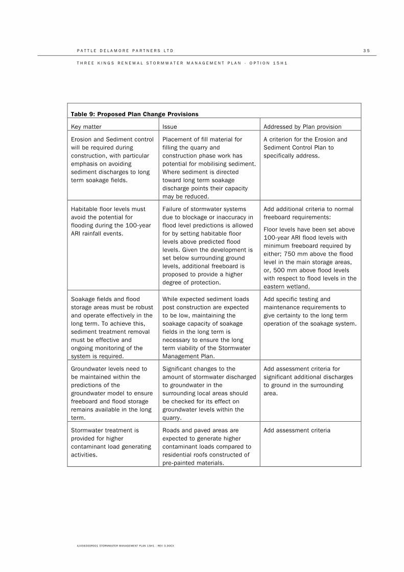
P A T T L E D E L A M O R E P A R T N E R S L T D 3 5
T H R E E K I N G S R E N E W A L S T O R M W A T E R M A N A G E M E N T P L A N - O P T I O N 1 5 H 1
AJ456300R001 STORMWATER MANAGEMENT PLAN 15H1 - REV 3.DOCX
Table 9: Proposed Plan Change Provisions
Key matter Issue Addressed by Plan provision
Erosion and Sediment control will be required during construction, with particular emphasis on avoiding sediment discharges to long term soakage fields.
Placement of fill material for filling the quarry and construction phase work has potential for mobilising sediment. Where sediment is directed toward long term soakage discharge points their capacity may be reduced.
A criterion for the Erosion and Sediment Control Plan to specifically address.
Habitable floor levels must avoid the potential for flooding during the 100-year ARI rainfall events.
Failure of stormwater systems due to blockage or inaccuracy in flood level predictions is allowed for by setting habitable floor levels above predicted flood levels. Given the development is set below surrounding ground levels, additional freeboard is proposed to provide a higher degree of protection.
Add additional criteria to normal freeboard requirements:
Floor levels have been set above 100-year ARI flood levels with minimum freeboard required by either; 750 mm above the flood level in the main storage areas, or, 500 mm above flood levels with respect to flood levels in the eastern wetland.
Soakage fields and flood storage areas must be robust and operate effectively in the long term. To achieve this, sediment treatment removal must be effective and ongoing monitoring of the system is required.
While expected sediment loads post construction are expected to be low, maintaining the soakage capacity of soakage fields in the long term is necessary to ensure the long term viability of the Stormwater Management Plan.
Add specific testing and maintenance requirements to give certainty to the long term operation of the soakage system.
Groundwater levels need to be maintained within the predictions of the groundwater model to ensure freeboard and flood storage remains available in the long term.
Significant changes to the amount of stormwater discharged to groundwater in the surrounding local areas should be checked for its effect on groundwater levels within the quarry.
Add assessment criteria for significant additional discharges to ground in the surrounding area.
Stormwater treatment is provided for higher contaminant load generating activities.
Roads and paved areas are expected to generate higher contaminant loads compared to residential roofs constructed of pre-painted materials.
Add assessment criteria
P A T T L E D E L A M O R E P A R T N E R S L T D 3 6
T H R E E K I N G S R E N E W A L S T O R M W A T E R M A N A G E M E N T P L A N - O P T I O N 1 5 H 1
AJ456300R001 STORMWATER MANAGEMENT PLAN 15H1 - REV 3.DOCX
7.0 Opportunities Provided by this Proposal
7.1 Soakage for Surrounding Areas
Fletcher has tested four new soakholes adjacent to Mt Eden Rd. Soakage rates were a
minimum of 40 L/s and some were taken as greater than 50 L/s as no constant water
head could be achieved during the test. These holes could be used to divert stormwater
from the existing catchpits on Mt Eden Rd which drain to the combined sewer.
Similarly, the combined sewer area around McCullough and Smallfield Avenues could be
diverted to soakage. Auckland Council is proposing to undertake soakage tests in this
area to identify specific opportunities.
A 0.3 m increase in groundwater level from additional soakage in the surrounding area
has been allowed for in setting the short term groundwater level.
7.2 Flood Storage
This assessment has conservatively assumed that there will be no long term pumping of
groundwater from the quarry to ensure that there is no risk to the development from
groundwater and stormwater up to the 100-year ARI rainfall event.
However, if pumping were to continue, groundwater levels could be maintained at RL 34
m and there would be an extremely large volume of potential soakage and flood storage
volume between this and the highest groundwater level of RL 58.5 m. If stormwater from
off site was conveyed to this underground storage volume, the load on the combined
sewer could be reduced and existing local flooding and sewage overflow problems could
be relieved.
8.0 Conclusions
The groundwater rise due to infiltration of water during the 10-year and 100-year ARI
rainfall events is 1.5 and 2 m, respectively. It has therefore been assumed that soil is
saturated up to RL 58.0 m and RL 58.5 m for the 10-year and 100-year ARI rainfall
events, respectively, allowing for no surface water storage below these levels.
Stormwater runoff from the 10-year and 100-year ARI rainfall events can be appropriately
managed through soakage and flood storage on site.
Flood storage can be provided so to manage 100-year ARI runoff volumes while making
conservative assumptions about the amount of soakage available.
The amount of freeboard to all habitable floors is such that all of the rainfall volume from
a 100-year ARI rainfall event can be accommodated on site.
In order to avoid flooding on the field in a 10-year ARI rainfall event, the ground level for
the field was set at RL 59.0 m. With this level, the 10-year ARI rainfall event can be
stored below RL 59 m in Area B and raising to RL 60.0 m in the northern cell of the
eastern wetland channel, though some overland flow paths may be higher than this.
P A T T L E D E L A M O R E P A R T N E R S L T D 3 7
T H R E E K I N G S R E N E W A L S T O R M W A T E R M A N A G E M E N T P L A N - O P T I O N 1 5 H 1
AJ456300R001 STORMWATER MANAGEMENT PLAN 15H1 - REV 3.DOCX
Stormwater quality treatment is provided in Pond A, swales the eastern wetland and in
individual rain-gardens for some paved areas and roads. Roof water quality will be
managed through the use of non-exposed metal products such as pre-painted steel.
Further work is necessary to validate and refine the assumptions, though these have been
consistently conservative throughout the process.
Overall it is considered that this Stormwater Management Plan provides a high level of
robustness for stormwater management at the Three Kings Renewal development.
Therefore, the Plan Change is supported in terms of stormwater management.
9.0 References
Auckland City Council, 1999 – Operative District Plan, Isthmus Section
Auckland City Council, 2003 - Soakage Design Manual, prepared by PDP
Auckland Regional Council, 1999 – Guidelines for the estimation of runoff in the Auckland
Region, Technical Publication 108
Auckland Regional Council, 2001 – Regional Plan: Air, Land, Water
http://www.aucklandcity.govt.nz/council/documents/regionalplans/airlandwater/Proposed%
20ALWP%20-%20Part%203%20-
%20Chapter%205%20Discharges%20to%20Land%20and%20Water,%20and%20Land%2
0Management.pdf
Auckland Regional Council, 2003 – Stormwater Treatment Devices, Design Guideline
Manual, Technical Publication 10
Auckland Council, 2010,
http://www.aucklandcouncil.govt.nz/SiteCollectionDocuments/aboutcouncil/planspoliciespu
blications/technicalpublications/tr2010066reviewoftp10waterqualityvolumeestimation.pdf
Auckland Council, 2013, Code of Practice for Land Development and Subdivision, Oct
2013, Part 4, Stormwater
http://www.aucklandcouncil.govt.nz/EN/environmentwaste/stormwater/Documents/stormwa
tercodeofpractice.pdf
Department of Building and Housing, Compliance Document of the New Zealand Building
Code, Clause E1, Surface Water, 2011
http://www.dbh.govt.nz/UserFiles/File/Publications/Building/Compliance-documents/E1-
surface-water-1st-edition-amendment-8.pdf
Ministry for the Environment, 2008, http://www.mfe.govt.nz/publications/climate/climate-
change-effects-on-flood-flow/index.html
Pattle Delamore Partners, 2002, Groundwater modelling of the Waitemata Group near
Three Kings Quarry, Prepared for Winstone Aggregates, 6 December 2002

P A T T L E D E L A M O R E P A R T N E R S L T D 3 8
T H R E E K I N G S R E N E W A L S T O R M W A T E R M A N A G E M E N T P L A N - O P T I O N 1 5 H 1
AJ456300R001 STORMWATER MANAGEMENT PLAN 15H1 - REV 3.DOCX
Pattle Delamore Partners, 2005, Global Aquifer Study, Report 2B, prepared for Auckland
City Council, Metrowater
Pattle Delamore Partners, 2008, Three Kings Quarry – Modelling of Cleanfill Drainage,
Prepared for Winstone Aggregates, 9 October 2008.

PATTLE DELAMORE PARTNERS LTD Appe
ndix AFigures
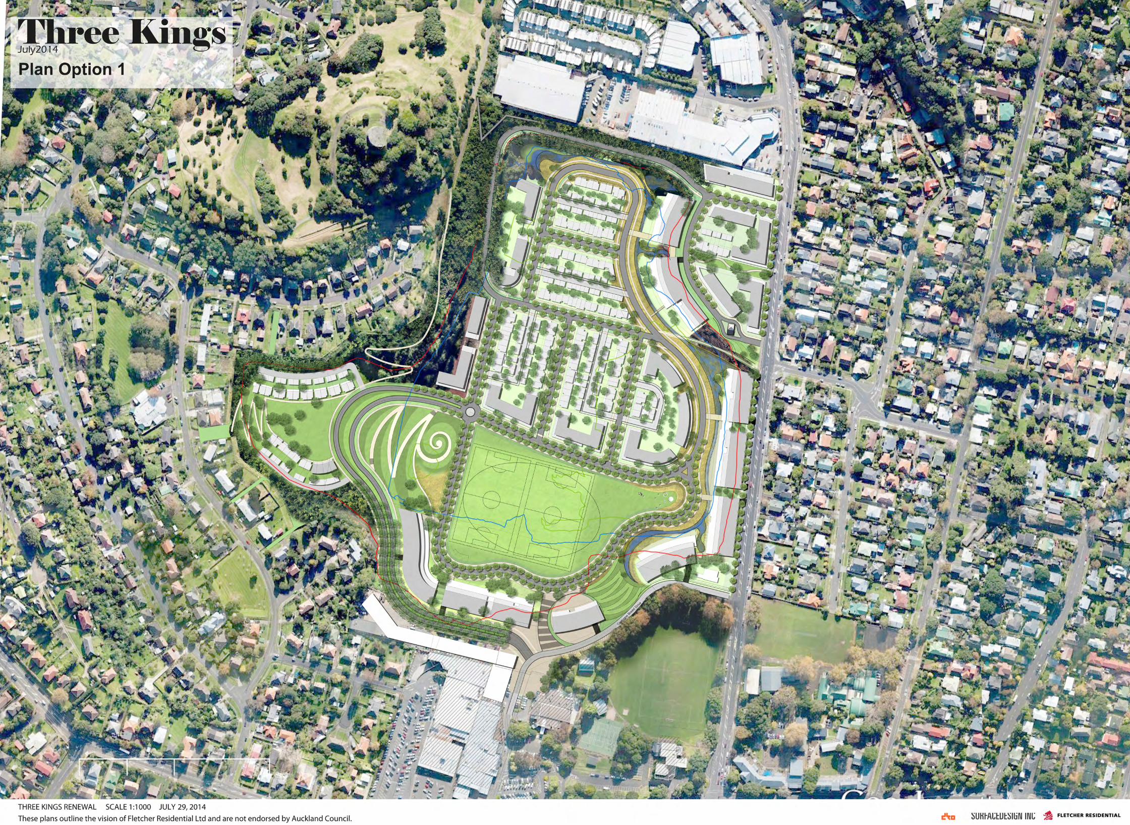
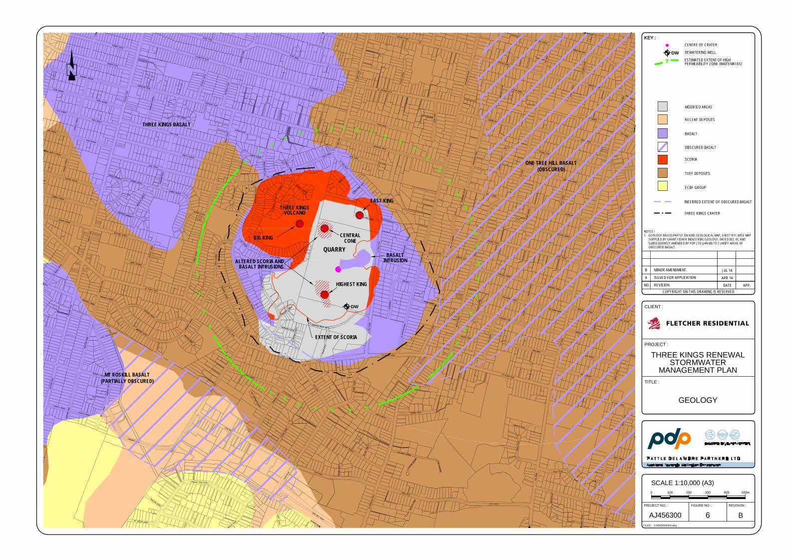
DW
THREE KINGSVOLCANO
QUARRY
HIGHEST KING
BASALTINTRUSION
EAST KING
ALTERED SCORIA ANDBASALT INTRUSIONS
BIG KING CENTRALCONE
EXTENT OF SCORIA
MT ROSKILL BASALT(PARTIALLY OBSCURED)
THREE KINGS BASALT
ONE TREE HILL BASALT(OBSCURED)
KEY :
PROJECT :
CLIENT :
THREE KINGS RENEWALSTORMWATER
MANAGEMENT PLANTITLE :
B6PROJECT NO. : FIGURE NO. :
FILED :
REVISION :
AJ456300D004.dwg
AJ456300
GEOLOGY
SCALE 1:10,000 (A3)1000 300200 500m400
NO. REVISIONCOPYRIGHT ON THIS DRAWING IS RESERVED
A ISSUED FOR APPLICATION
APP.DATE
APR 14
KEY :
NOTES :1. GEOLOGY BASED PARTLY ON IGNS GEOLOGICAL MAP, SHEET R11. BASE MAP
SUPPLIED BY GRANT FISHER INDUSTRIAL GEOLOGY, DATED DEC 01, ANDSUBSEQUENTLY AMENDED BY PDP LTD (JAN 08) TO CLARIFY AREAS OFOBSCURED BASALT.
SCORIA
BASALT
CENTRE OF CRATER
DEWATERING WELL
ESTIMATED EXTENT OF HIGHPERMEABILITY ZONE (WAITEMATAS)
THREE KINGS CRATER
INFERRED EXTENT OF OBSCURED BASALT
TUFF DEPOSITS
MODIFIED AREAS
ECBF GROUP
RECENT DEPOSITS
OBSCURED BASALT
DW
B MINOR AMENDMENT JUL 14
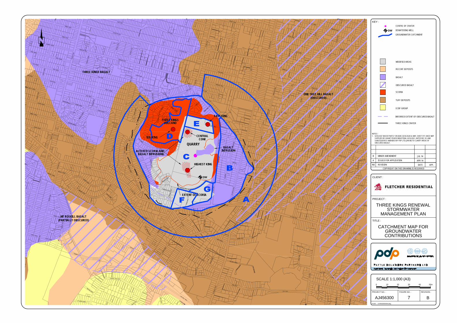
DW
THREE KINGSVOLCANO
QUARRY
HIGHEST KING
BASALTINTRUSION
EAST KING
ALTERED SCORIA ANDBASALT INTRUSIONS
BIG KING CENTRALCONE
EXTENT OF SCORIA
MT ROSKILL BASALT(PARTIALLY OBSCURED)
THREE KINGS BASALT
ONE TREE HILL BASALT(OBSCURED)
PROJECT :
CLIENT :
THREE KINGS RENEWALSTORMWATER
MANAGEMENT PLANTITLE :
B7PROJECT NO. : FIGURE NO. :
FILED :
REVISION :
AJ456300D004.dwg
AJ456300
CATCHMENT MAP FORGROUNDWATERCONTRIBUTIONS
SCALE 1:1,000 (A3)100 3020 50m40
NO. REVISIONCOPYRIGHT ON THIS DRAWING IS RESERVED
A ISSUED FOR APPLICATION
APP.DATE
APR 14
NOTES :1. GEOLOGY BASED PARTLY ON IGNS GEOLOGICAL MAP, SHEET R11. BASE MAP
SUPPLIED BY GRANT FISHER INDUSTRIAL GEOLOGY, DATED DEC 01, ANDSUBSEQUENTLY AMENDED BY PDP LTD (JAN 08) TO CLARIFY AREAS OFOBSCURED BASALT.
SCORIA
BASALT
THREE KINGS CRATER
INFERRED EXTENT OF OBSCURED BASALT
TUFF DEPOSITS
MODIFIED AREAS
ECBF GROUP
RECENT DEPOSITS
OBSCURED BASALT
KEY :CENTRE OF CRATER
DEWATERING WELL
GROUNDWATER CATCHMENT
DW
B MINOR AMENDMENT JUL 14
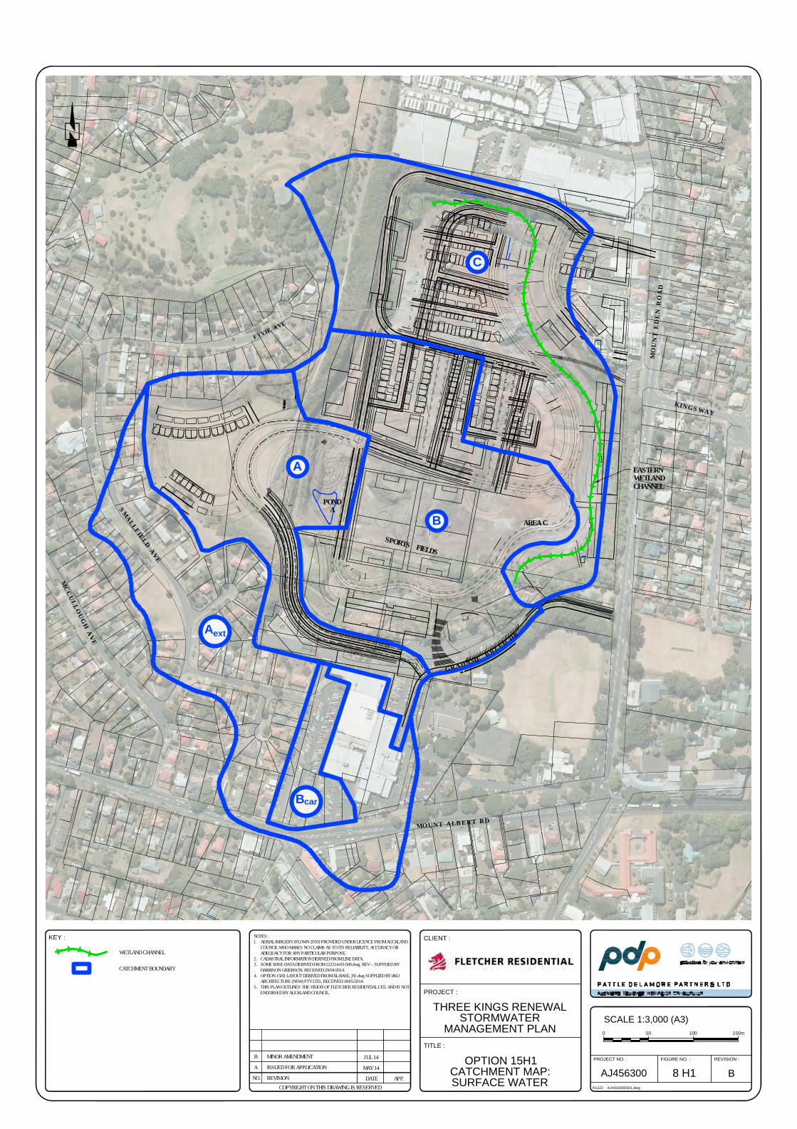
K I N G S W A Y
M O
U N
T E
D E
N R
O A
D
F Y V I E A V E
S M A L L F I E L D A V E
M O U N T A L B E R T R D
M C C U L L O U G H A V E
AREA C
PONDA
SPORTS FIELDS
B
A
ext
B
car
G R A H A M EB R E E D D
R
A
C
EASTERNWETLANDCHANNEL
KEY :
NOTES :1. AERIAL IMAGERY (FLOWN 2010) PROVIDED UNDER LICENCE FROM AUCKLAND
COUNCIL WHO MAKES NO CLAIMS AS TO ITS RELIABILITY, ACCURACY ORADEQUACY FOR ANY PARTICULAR PURPOSE.
2. CADASTRAL INFORMATION DERIVED FROM LINZ DATA.3. SOME BASE DATA DERIVED FROM 122314-03-500.dwg, REV -. SUPPLIED BY
HARRISON GRIERSON, RECEIVED 29/04/2014.4. OPTION 15H1 LAYOUT DERIVED FROM XL-BASE_H1.dwg SUPPLIED BY dKO
ARCHITECTURE (NSW) PTY LTD., RECEIVED 18/05/2014.5. THIS PLAN OUTLINES THE VISION OF FLETCHER RESIDENTIAL LTD. AND IS NOT
ENDORSED BY AUCKLAND COUNCIL. PROJECT :
CLIENT :
THREE KINGS RENEWAL
STORMWATER
MANAGEMENT PLAN
TITLE :
OPTION 15H1
CATCHMENT MAP:
SURFACE WATER
B8 H1
PROJECT NO. : FIGURE NO. :
FILED :
REVISION :
AJ456300D001.dwg
AJ456300NO. REVISIONCOPYRIGHT ON THIS DRAWING IS RESERVED
A ISSUED FOR APPLICATION
APP.DATE
MAY 14
SCALE 1:3,000 (A3)
0 50 150m100
WETLAND CHANNEL
CATCHMENT BOUNDARY
B MINOR AMENDMENT JUL 14
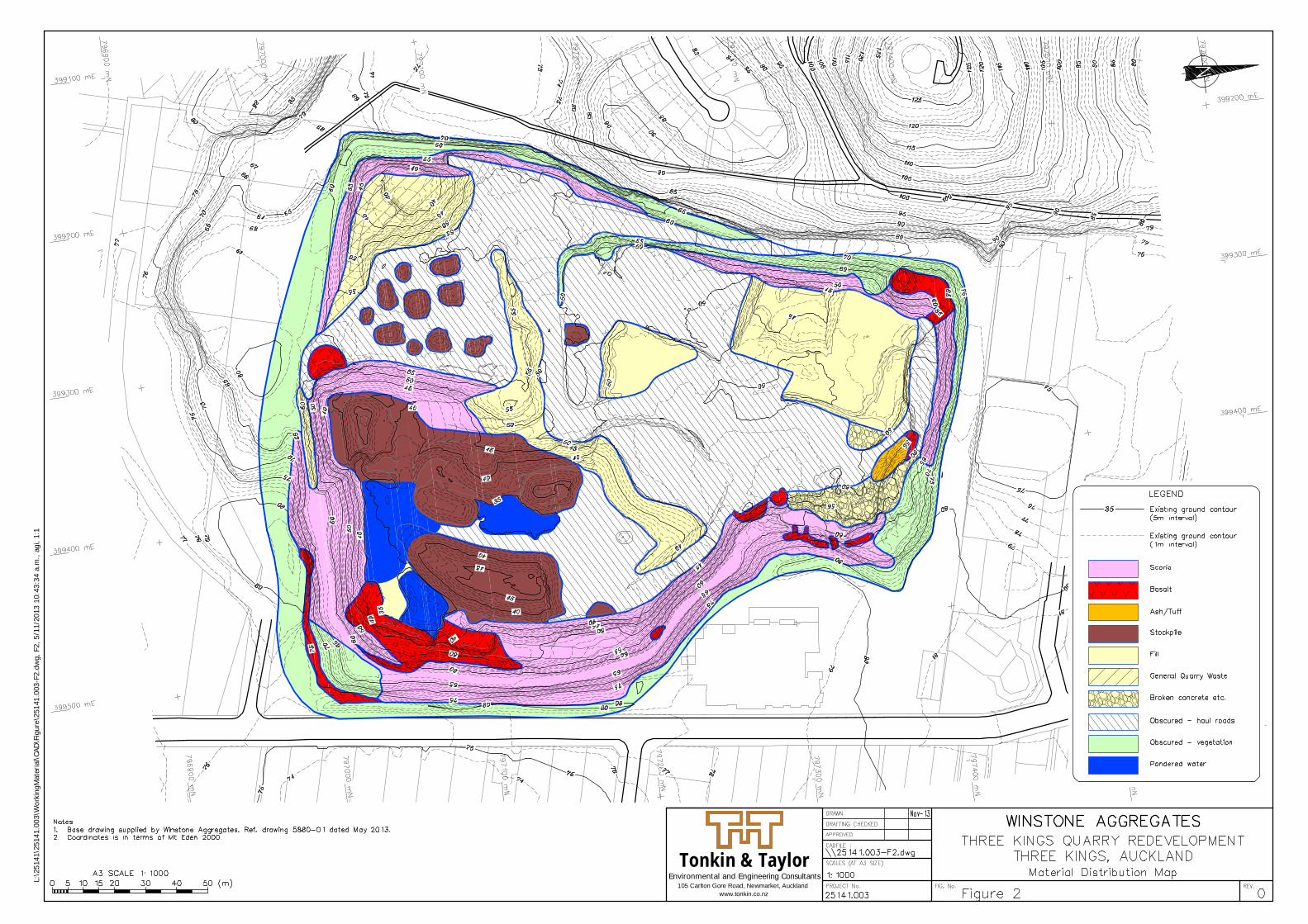
Environmental and Engineering ConsultantsTonkin & Taylor
105 Carlton Gore Road, Newmarket, Aucklandwww.tonkin.co.nz
L:\2
5141
\251
41.0
03\W
orki
ngM
ater
ial\C
AD\F
igur
e\25
141.
003-
F2.d
wg,
F2,
5/1
1/20
13 1
0:43
:34
a.m
., ag
i, 1:
1
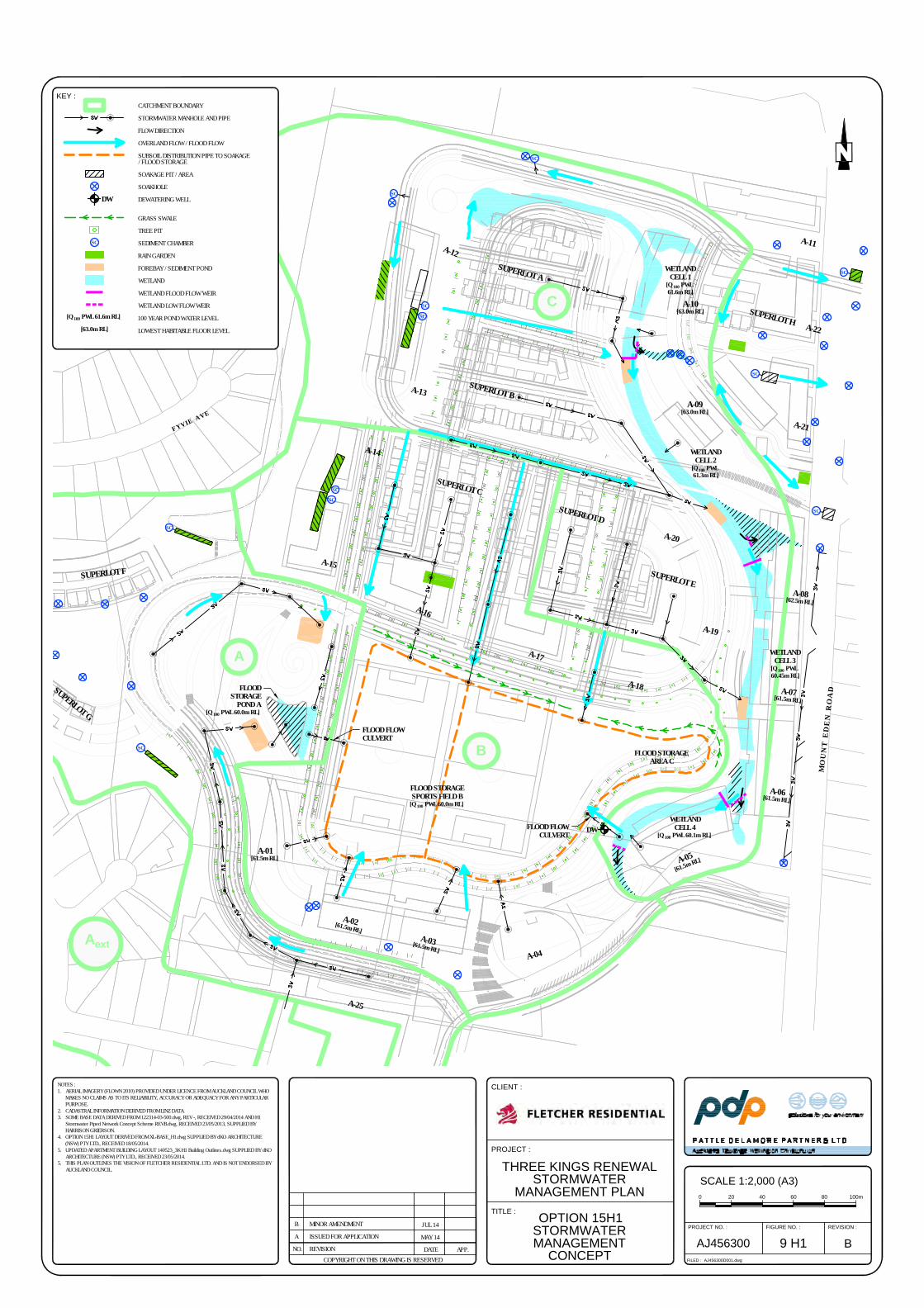
M O
U N
T E
D E
N R
O A
D
F Y V I E A V E
B
A
ext
SC
SC
SC
SC
SC
SC
FLOOD FLOWCULVERT
FLOOD STORAGEAREA C
FLOOD STORAGESPORTS FIELD B
[Q 100 PWL 60.0m RL]
FLOOD FLOWCULVERT
WETLANDCELL 4
[Q 100 PWL 60.1m RL]
WETLANDCELL 3
[Q 100 PWL60.45m RL]
WETLANDCELL 2
[Q 100 PWL61.3m RL]
WETLANDCELL 1
[Q 100 PWL61.6m RL]
SC
SC
SC
A
CSC
DW
FLOODSTORAGE
POND A[Q 100 PWL 60.0m RL]
SC
A-11
SUPERLOT A
SUPERLOT BA-13
A-02[61.5m RL]
A-04
A-01[61.5m RL]
A-15
A-14
SUPERLOT C
SUPERLOT D
A-09[63.0m RL]
A-05[61.5m RL]
A-03[61.5m RL]
A-08[62.5m RL]
A-16
A-17
A-25
A-10[63.0m RL]
A-18
A-22
SUPERLOT E
SUPERLOT H
A-19
A-20
A-21
SUPERLOT F
SUPERLOT G
A-12
A-07[61.5m RL]
A-06[61.5m RL]
NOTES :1. AERIAL IMAGERY (FLOWN 2010) PROVIDED UNDER LICENCE FROM AUCKLAND COUNCIL WHO
MAKES NO CLAIMS AS TO ITS RELIABILITY, ACCURACY OR ADEQUACY FOR ANY PARTICULARPURPOSE.
2. CADASTRAL INFORMATION DERIVED FROM LINZ DATA.3. SOME BASE DATA DERIVED FROM 122314-03-500.dwg, REV -, RECEIVED 29/04/2014 AND H1
Stormwater Piped Network Concept Scheme REVB.dwg, RECEIVED 23/05/2013, SUPPLIED BYHARRISON GRIERSON.
4. OPTION 15H1 LAYOUT DERIVED FROM XL-BASE_H1.dwg SUPPLIED BY dKO ARCHITECTURE(NSW) PTY LTD., RECEIVED 18/05/2014.
5. UPDATED APARTMENT BUILDING LAYOUT 140523_3K H1 Building Outlines.dwg SUPPLIED BY dKOARCHITECTURE (NSW) PTY LTD., RECEIVED 23/05/2014.
5. THIS PLAN OUTLINES THE VISION OF FLETCHER RESIDENTIAL LTD. AND IS NOT ENDORSED BYAUCKLAND COUNCIL.
PROJECT :
CLIENT :
THREE KINGS RENEWAL
STORMWATER
MANAGEMENT PLAN
TITLE :
OPTION 15H1
STORMWATER
MANAGEMENT
CONCEPT
B9 H1
PROJECT NO. : FIGURE NO. :
FILED :
REVISION :
AJ456300D001.dwg
AJ456300NO. REVISIONCOPYRIGHT ON THIS DRAWING IS RESERVED
A ISSUED FOR APPLICATION
APP.DATE
MAY 14
SCALE 1:2,000 (A3)
200 6040 100m80
KEY :
CATCHMENT BOUNDARY
STORMWATER MANHOLE AND PIPE
FLOW DIRECTION
OVERLAND FLOW / FLOOD FLOW
SUBSOIL DISTRIBUTION PIPE TO SOAKAGE/ FLOOD STORAGE
SOAKAGE PIT / AREA
SOAKHOLE
DEWATERING WELL
GRASS SWALE
TREE PIT
SEDIMENT CHAMBER
RAIN GARDEN
FOREBAY / SEDIMENT POND
WETLAND
WETLAND FLOOD FLOW WEIR
WETLAND LOW FLOW WEIR
100 YEAR POND WATER LEVEL
LOWEST HABITABLE FLOOR LEVEL
SC
DW
[Q 100 PWL 61.6m RL]
[63.0m RL]
B MINOR AMENDMENT JUL 14
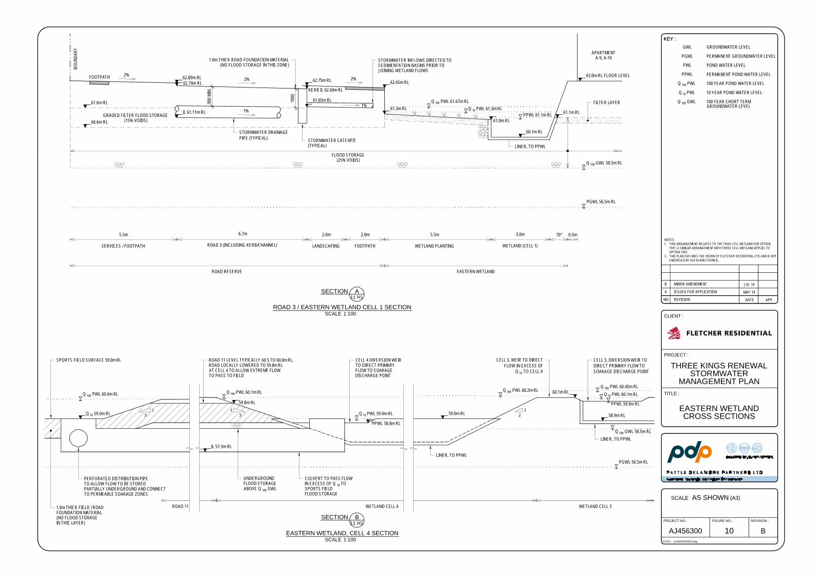
PPWL 61.1m RL
63.0m RL FLOOR LEVEL
LINER, TO PPWL
60.1m RL
61.1m RL
62.65m RL62.75m RL
61.0m RL
61.3m RL
62.89m RL
IL 61.11m RL
APARTMENTA-9, A-10
2%2%
2%
61.65m RL
5.5m
SERVICES / FOOTPATH
6.7m
ROAD 3 (INCLUDING KERB/CHANNEL)
2.0m
LANDSCAPING
2.0m
FOOTPATH
5.5m
WETLAND PLANTING
3.0m
WETLAND (CELL 1)
70° 0.5m
ROAD RESERVE
STORMWATER DRAINAGEPIPE (TYPICAL)
FLOOD STORAGE(25% VOIDS)
1%
KERB IL 62.60m RL62.74m RL
1000
900 M
IN.
1%
EASTERN WETLAND
PGWL 56.5m RL
Q 100 GWL 58.5m RL
Q 100 PWL 61.67m RLQ 10 PWL 61.3m RL
BOUN
DARY
FOOTPATH
STORMWATER INFLOWS DIRECTED TOSEDIMENTATION BASINS PRIOR TOJOINING WETLAND FLOWS
STORMWATER CATCHPIT(TYPICAL)
61.6m RL
60.6m RLGRADED FILTER FLOOD STORAGE
(15% VOIDS)
FILTER LAYER
1.0m THICK ROAD FOUNDATION MATERIAL(NO FLOOD STORAGE IN THIS ZONE)
31
SPORTS FIELD SURFACE 59.0m RL
1.0m THICK FIELD / ROADFOUNDATION MATERIAL(NO FLOOD STORAGEIN THIS LAYER)
Q 100 PWL 60.0m RL
Q 10 59.0m RL
ROAD 11
PERFORATED DISTRIBUTION PIPETO ALLOW FLOW TO BE STOREDPARTIALLY UNDERGROUND AND CONNECTTO PERMEABLE SOAKAGE ZONES
IL 57.3m RL
59.8m RL
31
CULVERT TO PASS FLOWIN EXCESS OF Q 10 TOSPORTS FIELDFLOOD STORAGE
ROAD 11 LEVEL TYPICALLY 60.5 TO 60.0m RL.ROAD LOCALLY LOWERED TO 59.8m RLAT CELL 4 TO ALLOW EXTREME FLOWTO PASS TO FIELD
CELL 4 DIVERSION WEIRTO DIRECT PRIMARYFLOW TO SOAKAGEDISCHARGE POINT
Q 100 PWL 60.1m RL
WETLAND CELL 4
Q 10 PWL 59.0m RL
PPWL 58.8m RL
UNDERGROUNDFLOOD STORAGEABOVE Q 100 GWL
21
60.1m RL
PPWL 59.9m RL
59.0m RL 58.9m RL
CELL 3, WEIR TO DIRECTFLOW IN EXCESS OF
Q 10 TO CELL 4
CELL 3, DIVERSION WEIR TODIRECT PRIMARY FLOW TOSOAKAGE DISCHARGE POINT
LINER, TO PPWL
LINER, TO PPWLPGWL 56.5m RL
Q 100 PWL 60.45m RLQ 10 PWL 60.1m RL
WETLAND CELL 3
Q 100 GWL 58.5m RL
Q 100 PWL 60.2m RL
KEY :
PROJECT :
CLIENT :
THREE KINGS RENEWALSTORMWATER
MANAGEMENT PLANTITLE :
B10PROJECT NO. : FIGURE NO. :
FILED :
REVISION :
AJ456300D003.dwg
AJ456300
KEY :
NO. REVISION
A ISSUED FOR APPLICATION
APP.DATE
MAY 14
EASTERN WETLANDCROSS SECTIONS
SCALE (A3)AS SHOWN
GROUNDWATER LEVEL
PERMANENT GROUNDWATER LEVEL
POND WATER LEVEL
PERMANENT POND WATER LEVEL
100 YEAR POND WATER LEVEL
10 YEAR POND WATER LEVEL
100 YEAR SHORT TERMGROUNDWATER LEVEL
SECTION
SCALE
A11 H1
ROAD 3 / EASTERN WETLAND CELL 1 SECTION1:100
SECTION
SCALE
B11 H1
EASTERN WETLAND, CELL 4 SECTION1:100
GWL
PGWL
PWL
PPWL
Q 100 PWL
Q 10 PWL
Q 100 GWL
NOTES:1. THIS ARRANGEMENT RELATES TO THE FOUR CELL WETLAND FOR OPTION
15H1. A SIMILAR ARRANGEMENT WITH THREE CELL WETLAND APPLIES TOOPTION 15H2.
2. THIS PLAN OUTLINES THE VISION OF FLETCHER RESIDENTIAL LTD. AND IS NOTENDORSED BY AUCKLAND COUNCIL.
B MINOR AMENDMENT JUL 14
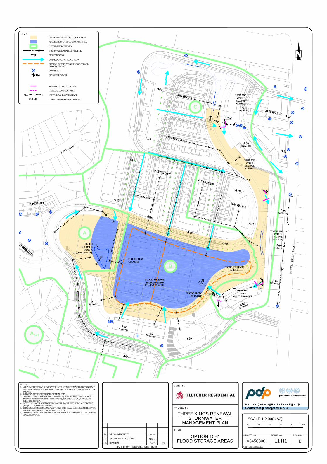
M O
U N
T E
D E
N R
O A
D
F Y V I E A V E
B
A
ext
FLOOD FLOWCULVERT
FLOOD STORAGEAREA C
FLOOD STORAGESPORTS FIELD B
[Q 100 PWL 60.0m RL]
FLOOD FLOWCULVERT
WETLANDCELL 4
[Q 100 PWL 60.1m RL]
WETLANDCELL 3
[Q 100 PWL60.45m RL]
WETLANDCELL 2
[Q 100 PWL61.3m RL]
WETLANDCELL 1
[Q 100 PWL61.6m RL]
A
C
DW
FLOODSTORAGE
POND A[Q 100 PWL 60.0m RL]
A-11
SUPERLOT A
SUPERLOT BA-13
A-02[61.5m RL]
A-04
A-01[61.5m RL]
A-15
A-14
SUPERLOT C
SUPERLOT D
A-09[63.0m RL]
A-05[61.5m RL]
A-03[61.5m RL]
A-08[62.5m RL]
A-16
A-17
A-25
A-10[63.0m RL]
A-18
A-22
SUPERLOT E
SUPERLOT H
A-19
A-20
A-21
SUPERLOT F
SUPERLOT G
A-12
A-07[61.5m RL]
A-06[61.5m RL]
A
1
0
B
1
0
NOTES :1. AERIAL IMAGERY (FLOWN 2010) PROVIDED UNDER LICENCE FROM AUCKLAND COUNCIL WHO
MAKES NO CLAIMS AS TO ITS RELIABILITY, ACCURACY OR ADEQUACY FOR ANY PARTICULARPURPOSE.
2. CADASTRAL INFORMATION DERIVED FROM LINZ DATA.3. SOME BASE DATA DERIVED FROM 122314-03-500.dwg, REV -, RECEIVED 29/04/2014 AND H1
Stormwater Piped Network Concept Scheme REVB.dwg, RECEIVED 23/05/2013, SUPPLIED BYHARRISON GRIERSON.
4. OPTION 15H1 LAYOUT DERIVED FROM XL-BASE_H1.dwg SUPPLIED BY dKO ARCHITECTURE(NSW) PTY LTD., RECEIVED 18/05/2014.
5. UPDATED APARTMENT BUILDING LAYOUT 140523_3K H1 Building Outlines.dwg SUPPLIED BY dKOARCHITECTURE (NSW) PTY LTD., RECEIVED 23/05/2014.
5. THIS PLAN OUTLINES THE VISION OF FLETCHER RESIDENTIAL LTD. AND IS NOT ENDORSED BYAUCKLAND COUNCIL.
PROJECT :
CLIENT :
THREE KINGS RENEWAL
STORMWATER
MANAGEMENT PLAN
TITLE :
OPTION 15H1
FLOOD STORAGE AREAS B11 H1
PROJECT NO. : FIGURE NO. :
FILED :
REVISION :
AJ456300D001.dwg
AJ456300NO. REVISIONCOPYRIGHT ON THIS DRAWING IS RESERVED
A ISSUED FOR APPLICATION
APP.DATE
MAY 14
SCALE 1:2,000 (A3)
200 6040 100m80
KEY :
UNDERGROUND FLOOD STORAGE AREA
ABOVE GROUND FLOOD STORAGE AREA
CATCHMENT BOUNDARY
STORMWATER MANHOLE AND PIPE
FLOW DIRECTION
OVERLAND FLOW / FLOOD FLOW
SUBSOIL DISTRIBUTION PIPE TO SOAKAGE/ FLOOD STORAGE
SOAKHOLE
DEWATERING WELL
WETLAND FLOOD FLOW WEIR
WETLAND LOW FLOW WEIR
100 YEAR POND WATER LEVEL
LOWEST HABITABLE FLOOR LEVEL
DW
[Q 100 PWL 61.6m RL]
[63.0m RL]
B MINOR AMENDMENT JUL 14

PATTLE DELAMORE PARTNERS LTD
Appe
ndix BS
urface Water M
odel Results
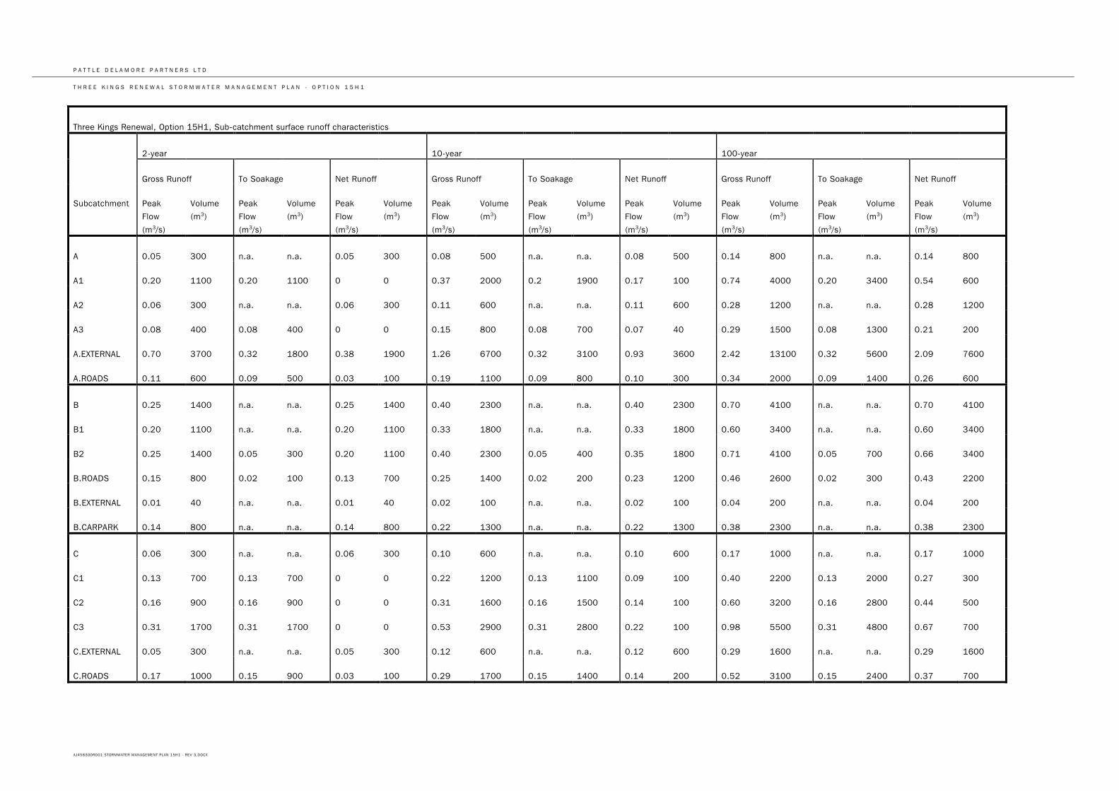
P A T T L E D E L A M O R E P A R T N E R S L T D
T H R E E K I N G S R E N E W A L S T O R M W A T E R M A N A G E M E N T P L A N - O P T I O N 1 5 H 1
AJ456300R001 STORMWATER MANAGEMENT PLAN 15H1 - REV 3.DOCX
Three Kings Renewal, Option 15H1, Sub-catchment surface runoff characteristics
2-year 10-year 100-year
Gross Runoff To Soakage Net Runoff Gross Runoff To Soakage Net Runoff Gross Runoff To Soakage Net Runoff
Subcatchment Peak
Flow
(m3/s)
Volume
(m3)
Peak
Flow
(m3/s)
Volume
(m3)
Peak
Flow
(m3/s)
Volume
(m3)
Peak
Flow
(m3/s)
Volume
(m3)
Peak
Flow
(m3/s)
Volume
(m3)
Peak
Flow
(m3/s)
Volume
(m3)
Peak
Flow
(m3/s)
Volume
(m3)
Peak
Flow
(m3/s)
Volume
(m3)
Peak
Flow
(m3/s)
Volume
(m3)
A 0.05 300 n.a. n.a. 0.05 300 0.08 500 n.a. n.a. 0.08 500 0.14 800 n.a. n.a. 0.14 800
A1 0.20 1100 0.20 1100 0 0 0.37 2000 0.2 1900 0.17 100 0.74 4000 0.20 3400 0.54 600
A2 0.06 300 n.a. n.a. 0.06 300 0.11 600 n.a. n.a. 0.11 600 0.28 1200 n.a. n.a. 0.28 1200
A3 0.08 400 0.08 400 0 0 0.15 800 0.08 700 0.07 40 0.29 1500 0.08 1300 0.21 200
A.EXTERNAL 0.70 3700 0.32 1800 0.38 1900 1.26 6700 0.32 3100 0.93 3600 2.42 13100 0.32 5600 2.09 7600
A.ROADS 0.11 600 0.09 500 0.03 100 0.19 1100 0.09 800 0.10 300 0.34 2000 0.09 1400 0.26 600
B 0.25 1400 n.a. n.a. 0.25 1400 0.40 2300 n.a. n.a. 0.40 2300 0.70 4100 n.a. n.a. 0.70 4100
B1 0.20 1100 n.a. n.a. 0.20 1100 0.33 1800 n.a. n.a. 0.33 1800 0.60 3400 n.a. n.a. 0.60 3400
B2 0.25 1400 0.05 300 0.20 1100 0.40 2300 0.05 400 0.35 1800 0.71 4100 0.05 700 0.66 3400
B.ROADS 0.15 800 0.02 100 0.13 700 0.25 1400 0.02 200 0.23 1200 0.46 2600 0.02 300 0.43 2200
B.EXTERNAL 0.01 40 n.a. n.a. 0.01 40 0.02 100 n.a. n.a. 0.02 100 0.04 200 n.a. n.a. 0.04 200
B.CARPARK 0.14 800 n.a. n.a. 0.14 800 0.22 1300 n.a. n.a. 0.22 1300 0.38 2300 n.a. n.a. 0.38 2300
C 0.06 300 n.a. n.a. 0.06 300 0.10 600 n.a. n.a. 0.10 600 0.17 1000 n.a. n.a. 0.17 1000
C1 0.13 700 0.13 700 0 0 0.22 1200 0.13 1100 0.09 100 0.40 2200 0.13 2000 0.27 300
C2 0.16 900 0.16 900 0 0 0.31 1600 0.16 1500 0.14 100 0.60 3200 0.16 2800 0.44 500
C3 0.31 1700 0.31 1700 0 0 0.53 2900 0.31 2800 0.22 100 0.98 5500 0.31 4800 0.67 700
C.EXTERNAL 0.05 300 n.a. n.a. 0.05 300 0.12 600 n.a. n.a. 0.12 600 0.29 1600 n.a. n.a. 0.29 1600
C.ROADS 0.17 1000 0.15 900 0.03 100 0.29 1700 0.15 1400 0.14 200 0.52 3100 0.15 2400 0.37 700

PATTLE DELAMORE PARTNERS LTD
Appe
ndix CS
oakage Test Results: M
t Eden Road /
Upper D
evelopment Area
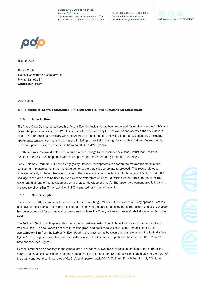
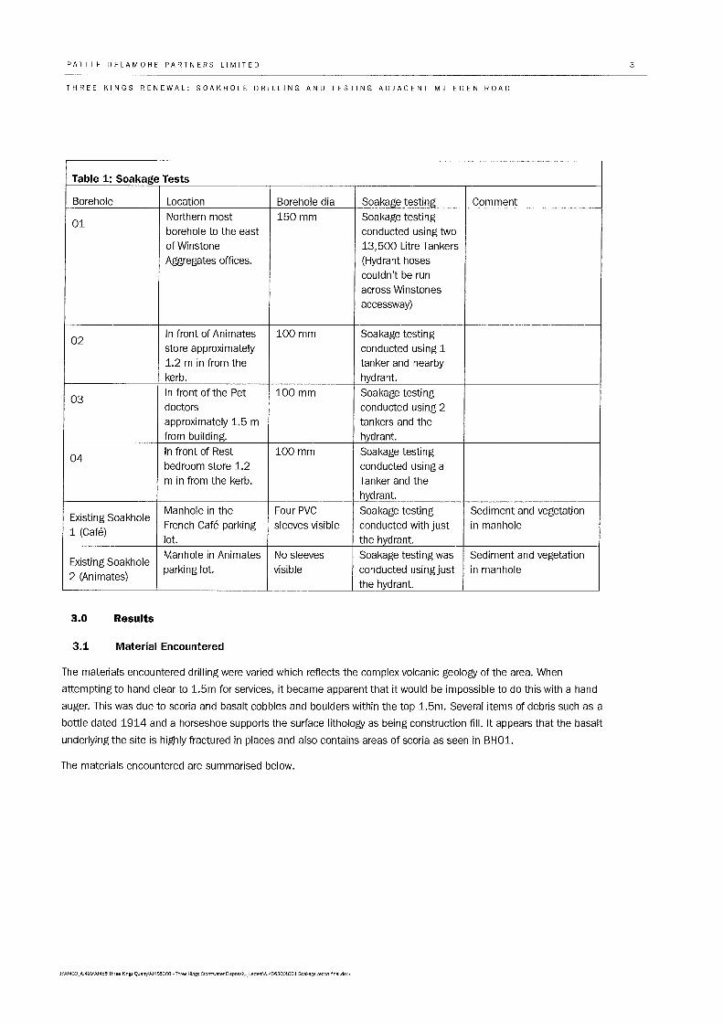
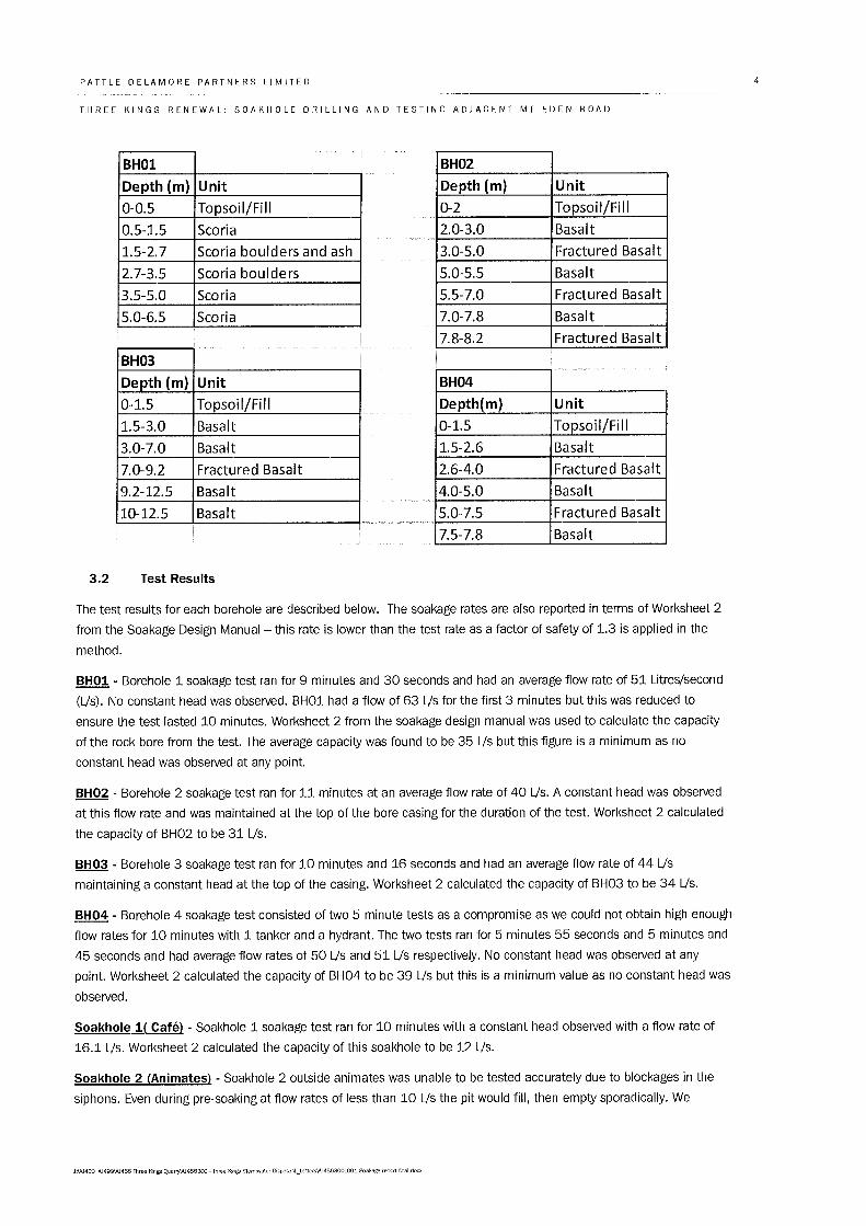
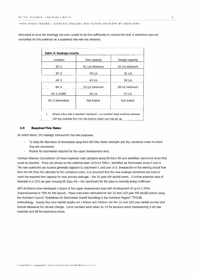
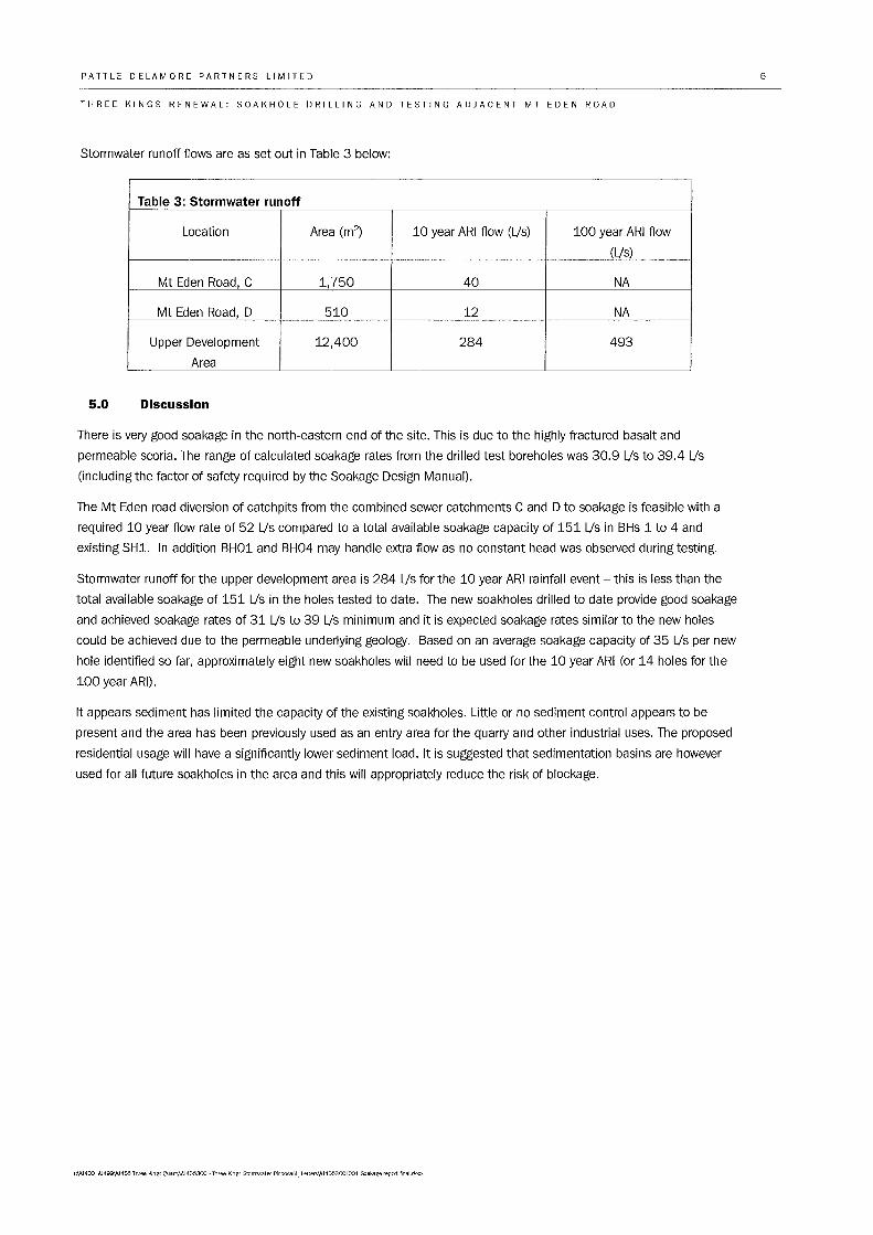
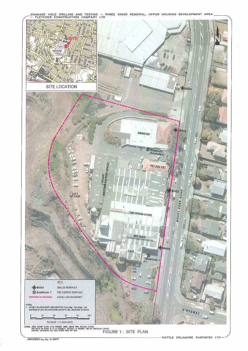
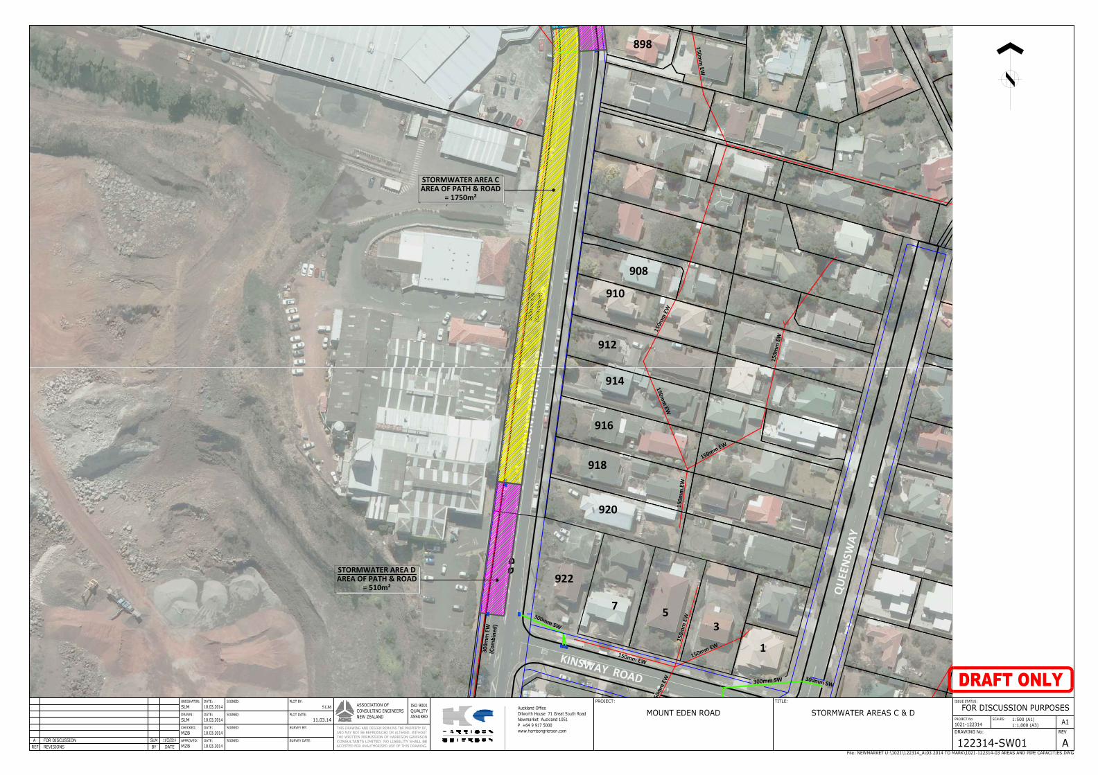
MO
UN
T ED
EN R
OAD
KINSWAY ROAD
QUE
ENSW
AY
150mm
EW
300mm SW
300mm SW300mm SW15
0mm
EW
150mm EW150mm EW
150m
m E
W
300m
m E
W(C
ombi
ned)
300m
m E
W(C
ombi
ned)
150m
m E
W
150mm EW
150m
m E
W
150mm
EW
150m
m E
W
922
920
918
916
914
912
910
908
7 53
1
898
STORMWATER AREA CAREA OF PATH & ROAD
= 1750m²
STORMWATER AREA DAREA OF PATH & ROAD
= 510m²
SLM

PATTLE DELAMORE PARTNERS LTD
Appe
ndix DM
atrix of Storm
water
Managem
ent O
ptions
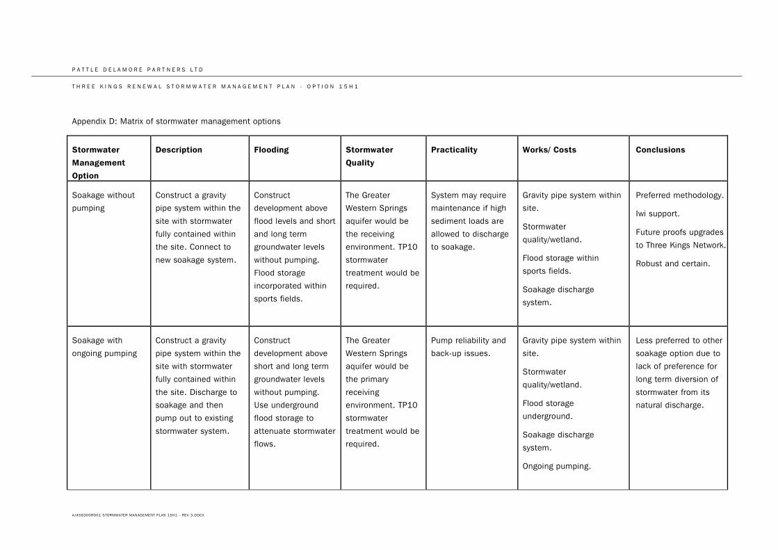
P A T T L E D E L A M O R E P A R T N E R S L T D
T H R E E K I N G S R E N E W A L S T O R M W A T E R M A N A G E M E N T P L A N - O P T I O N 1 5 H 1
AJ456300R001 STORMWATER MANAGEMENT PLAN 15H1 - REV 3.DOCX
Appendix D: Matrix of stormwater management options
Stormwater
Management
Option
Description Flooding Stormwater
Quality
Practicality Works/ Costs Conclusions
Soakage without
pumping
Construct a gravity
pipe system within the
site with stormwater
fully contained within
the site. Connect to
new soakage system.
Construct
development above
flood levels and short
and long term
groundwater levels
without pumping.
Flood storage
incorporated within
sports fields.
The Greater
Western Springs
aquifer would be
the receiving
environment. TP10
stormwater
treatment would be
required.
System may require
maintenance if high
sediment loads are
allowed to discharge
to soakage.
Gravity pipe system within
site.
Stormwater
quality/wetland.
Flood storage within
sports fields.
Soakage discharge
system.
Preferred methodology.
Iwi support.
Future proofs upgrades
to Three Kings Network.
Robust and certain.
Soakage with
ongoing pumping
Construct a gravity
pipe system within the
site with stormwater
fully contained within
the site. Discharge to
soakage and then
pump out to existing
stormwater system.
Construct
development above
short and long term
groundwater levels
without pumping.
Use underground
flood storage to
attenuate stormwater
flows.
The Greater
Western Springs
aquifer would be
the primary
receiving
environment. TP10
stormwater
treatment would be
required.
Pump reliability and
back-up issues.
Gravity pipe system within
site.
Stormwater
quality/wetland.
Flood storage
underground.
Soakage discharge
system.
Ongoing pumping.
Less preferred to other
soakage option due to
lack of preference for
long term diversion of
stormwater from its
natural discharge.
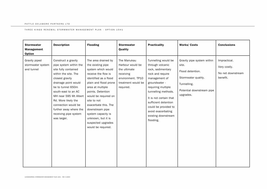
P A T T L E D E L A M O R E P A R T N E R S L T D
T H R E E K I N G S R E N E W A L S T O R M W A T E R M A N A G E M E N T P L A N - O P T I O N 1 5 H 1
AJ456300R001 STORMWATER MANAGEMENT PLAN 15H1 - REV 3.DOCX
Stormwater
Management
Option
Description Flooding Stormwater
Quality Practicality Works/ Costs Conclusions
Gravity piped
stormwater system
and tunnel
Construct a gravity
pipe system within the
site fully contained
within the site. The
closest gravity
drainage point would
be to tunnel 650m
south-east to an AC
MH near 595 Mt Albert
Rd. More likely the
connection would be
further away where the
receiving pipe system
was larger.
The area drained by
the existing pipe
system which would
receive the flow is
identified as a flood
plain and flood prone
area at multiple
points. Detention
would be required on
site to not
exacerbate this. The
downstream pipe
system capacity is
unknown, but it is
suspected upgrades
would be required.
The Manukau
Harbour would be
the ultimate
receiving
environment. TP10
treatment would be
required.
Tunnelling would be
through volcanic
rock, sedimentary
rock and require
management of
groundwater -
requiring multiple
tunnelling methods.
It is not certain that
sufficient detention
could be provided to
avoid exacerbating
existing downstream
flooding.
Gravity pipe system within
site.
Flood detention.
Stormwater quality.
Tunnelling.
Potential downstream pipe
upgrades.
Impractical.
Very costly.
No net downstream
benefit.
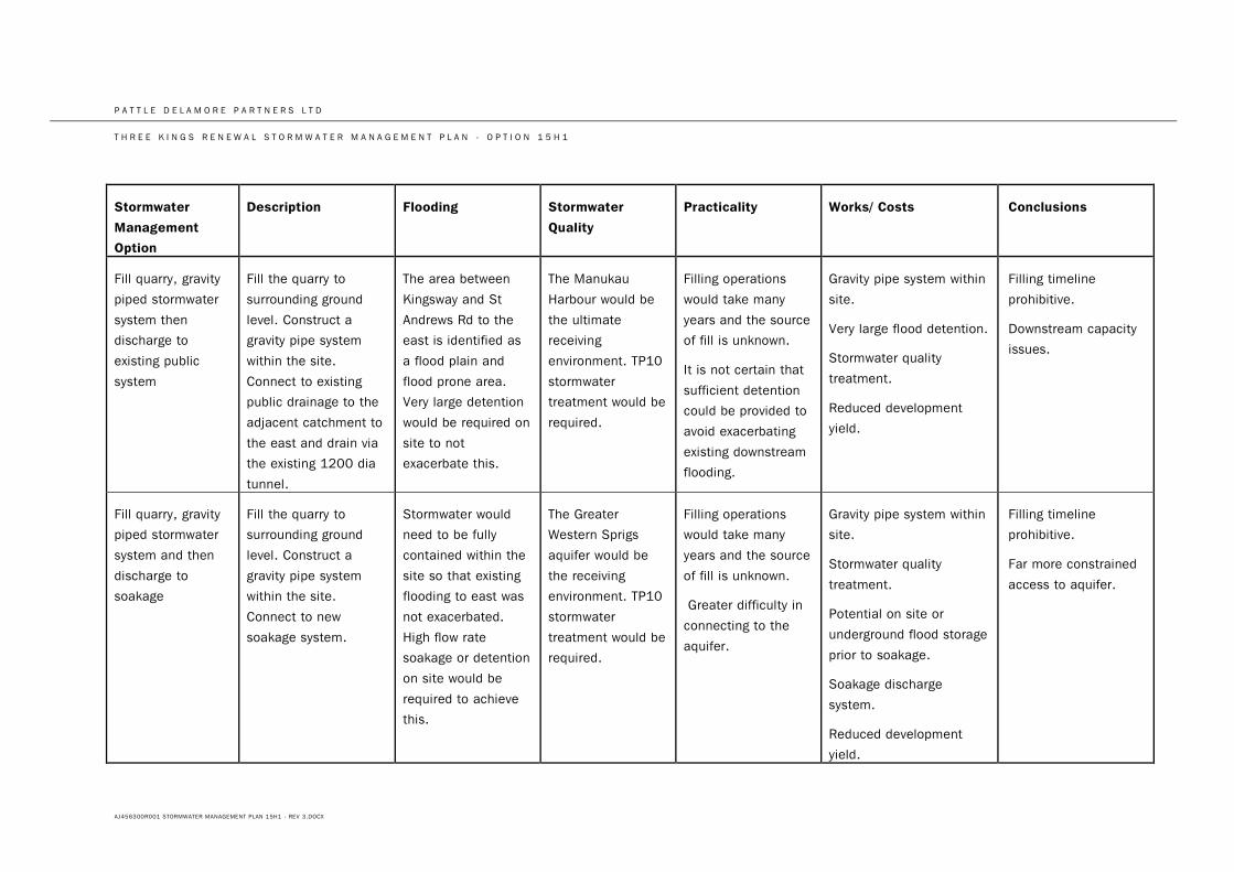
P A T T L E D E L A M O R E P A R T N E R S L T D
T H R E E K I N G S R E N E W A L S T O R M W A T E R M A N A G E M E N T P L A N - O P T I O N 1 5 H 1
AJ456300R001 STORMWATER MANAGEMENT PLAN 15H1 - REV 3.DOCX
Stormwater
Management
Option
Description Flooding Stormwater
Quality Practicality Works/ Costs Conclusions
Fill quarry, gravity
piped stormwater
system then
discharge to
existing public
system
Fill the quarry to
surrounding ground
level. Construct a
gravity pipe system
within the site.
Connect to existing
public drainage to the
adjacent catchment to
the east and drain via
the existing 1200 dia
tunnel.
The area between
Kingsway and St
Andrews Rd to the
east is identified as
a flood plain and
flood prone area.
Very large detention
would be required on
site to not
exacerbate this.
The Manukau
Harbour would be
the ultimate
receiving
environment. TP10
stormwater
treatment would be
required.
Filling operations
would take many
years and the source
of fill is unknown.
It is not certain that
sufficient detention
could be provided to
avoid exacerbating
existing downstream
flooding.
Gravity pipe system within
site.
Very large flood detention.
Stormwater quality
treatment.
Reduced development
yield.
Filling timeline
prohibitive.
Downstream capacity
issues.
Fill quarry, gravity
piped stormwater
system and then
discharge to
soakage
Fill the quarry to
surrounding ground
level. Construct a
gravity pipe system
within the site.
Connect to new
soakage system.
Stormwater would
need to be fully
contained within the
site so that existing
flooding to east was
not exacerbated.
High flow rate
soakage or detention
on site would be
required to achieve
this.
The Greater
Western Sprigs
aquifer would be
the receiving
environment. TP10
stormwater
treatment would be
required.
Filling operations
would take many
years and the source
of fill is unknown.
Greater difficulty in
connecting to the
aquifer.
Gravity pipe system within
site.
Stormwater quality
treatment.
Potential on site or
underground flood storage
prior to soakage.
Soakage discharge
system.
Reduced development
yield.
Filling timeline
prohibitive.
Far more constrained
access to aquifer.