Fisica Medica 4 – TC
43
Fisica Medica 4 – TC Corso di laurea in Fisica A.A. 2007-2008
Transcript of Fisica Medica 4 – TC
Fisica Medica
4 – TC
Corso di laurea in FisicaA.A. 2007-2008
Computed Tomography Principles
• 1. Projection measurement
• 2. Scanner systems
• 3. Scanning modes
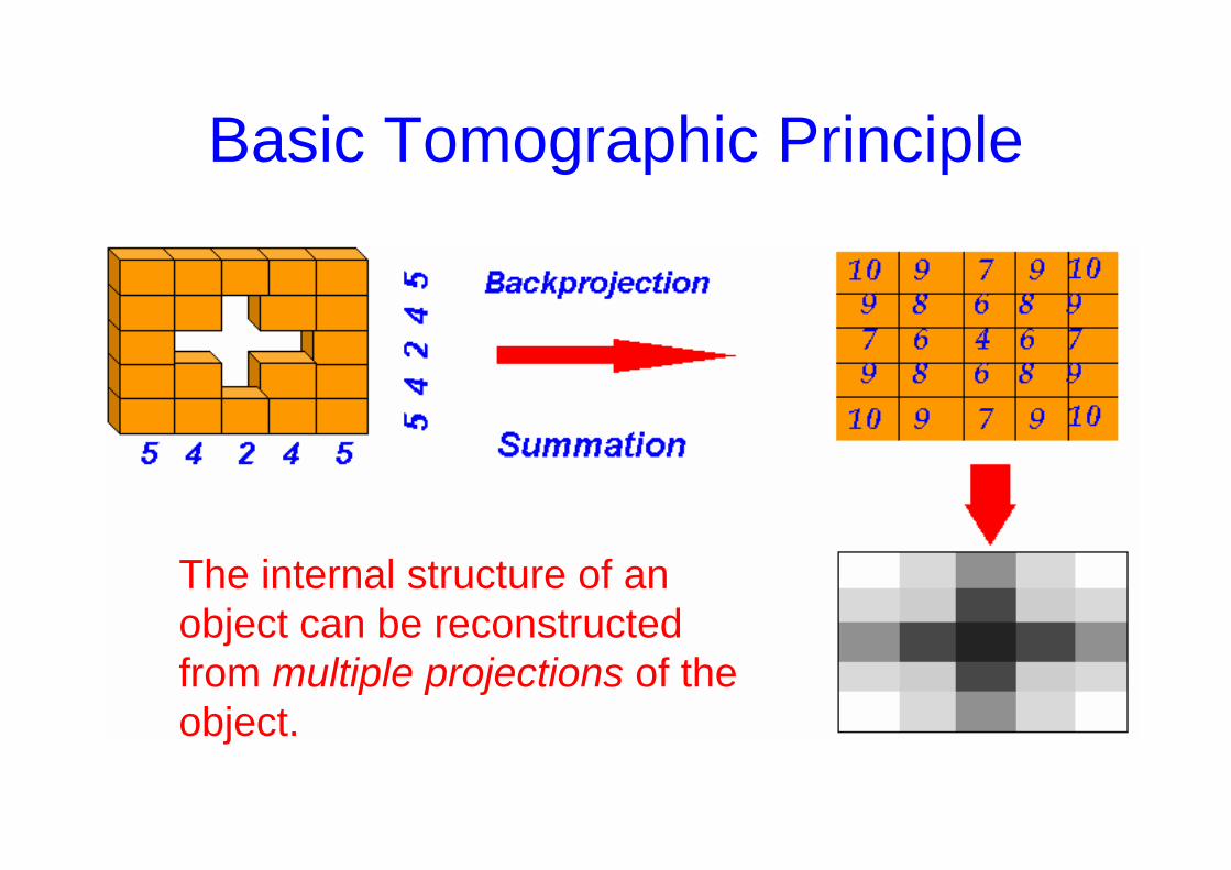
Basic Tomographic Principle
The internal structure of anobject can be reconstructedfrom multiple projections of the object.
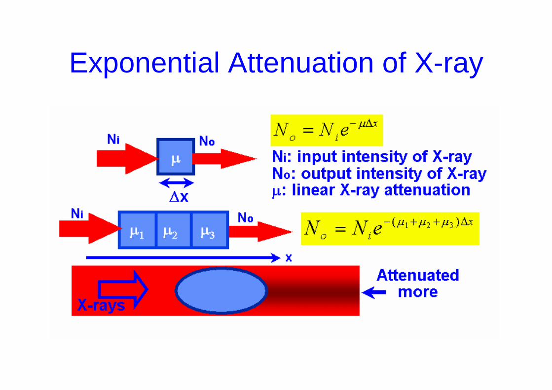
Exponential Attenuation of X-ray
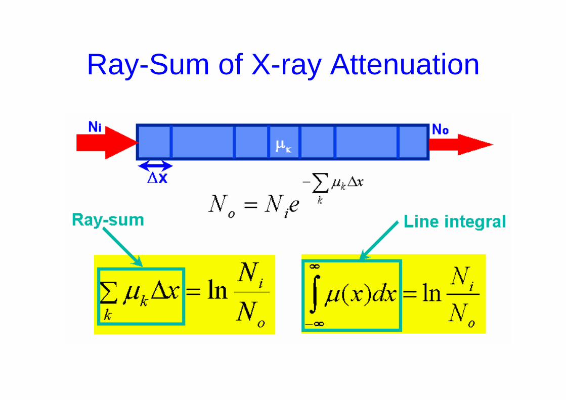
Ray-Sum of X-ray Attenuation
Computed Tomography Principles
• 1. Projection measurement
• 2. Scanning modes
• 3. Scanner systems
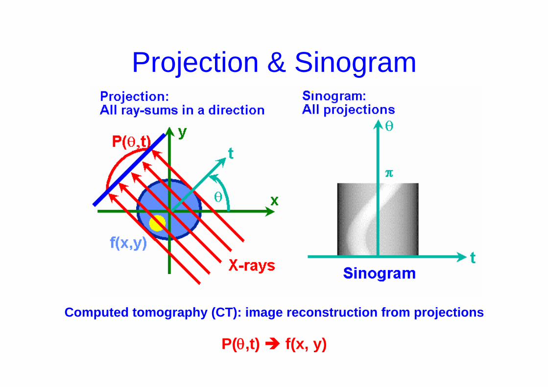
Projection & Sinogram
Computed tomography (CT): image reconstruction from projections
P(θ,t) f(x, y)
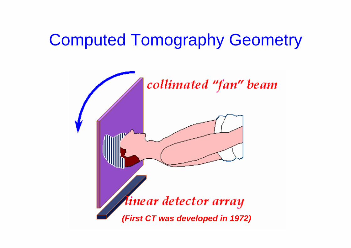
Computed Tomography Geometry
(First CT was developed in 1972)
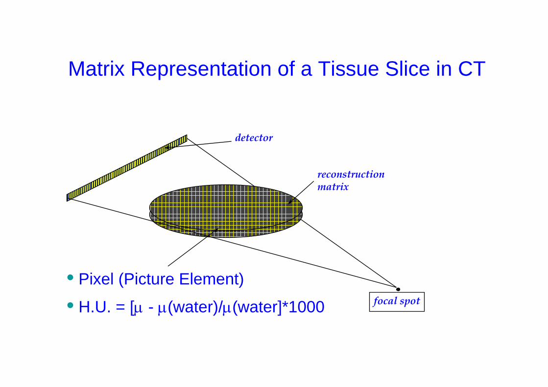
reconstructionmatrix
focal spot
detector
Matrix Representation of a Tissue Slice in CT
• Pixel (Picture Element)
• H.U. = [µ - µ(water)/µ(water]*1000
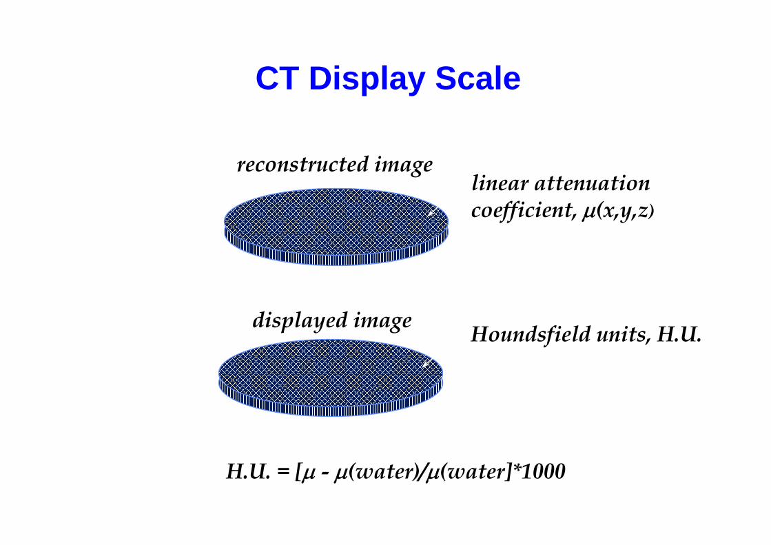
CT Display Scale
linear attenuationcoefficient, µ(x,y,z)
reconstructed image
displayed image Houndsfield units, H.U.
H.U. = [µ - µ(water)/µ(water]*1000
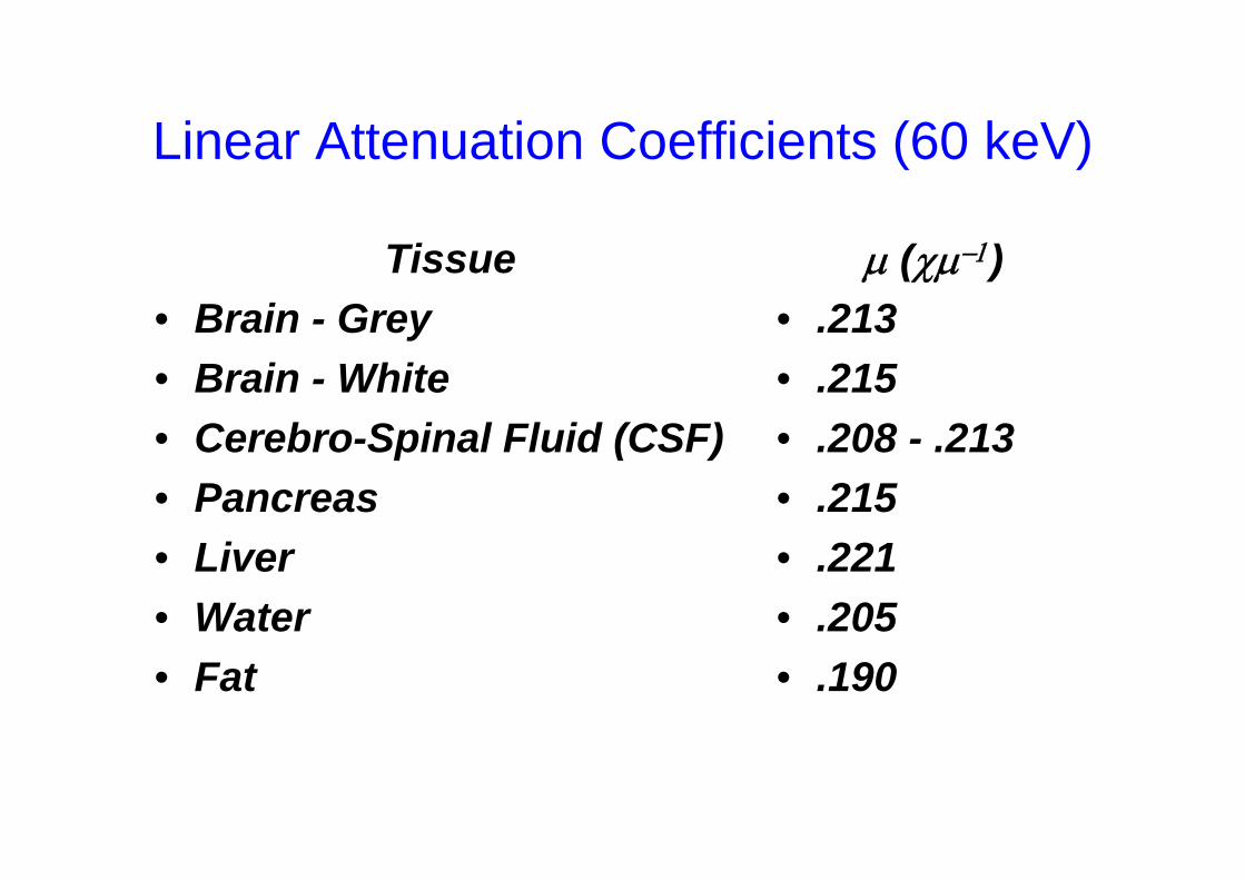
Linear Attenuation Coefficients (60 keV)
Tissue• Brain - Grey• Brain - White• Cerebro-Spinal Fluid (CSF) • Pancreas • Liver• Water • Fat
µ (χµ−1)• .213• .215• .208 - .213 • .215 • .221• .205 • .190
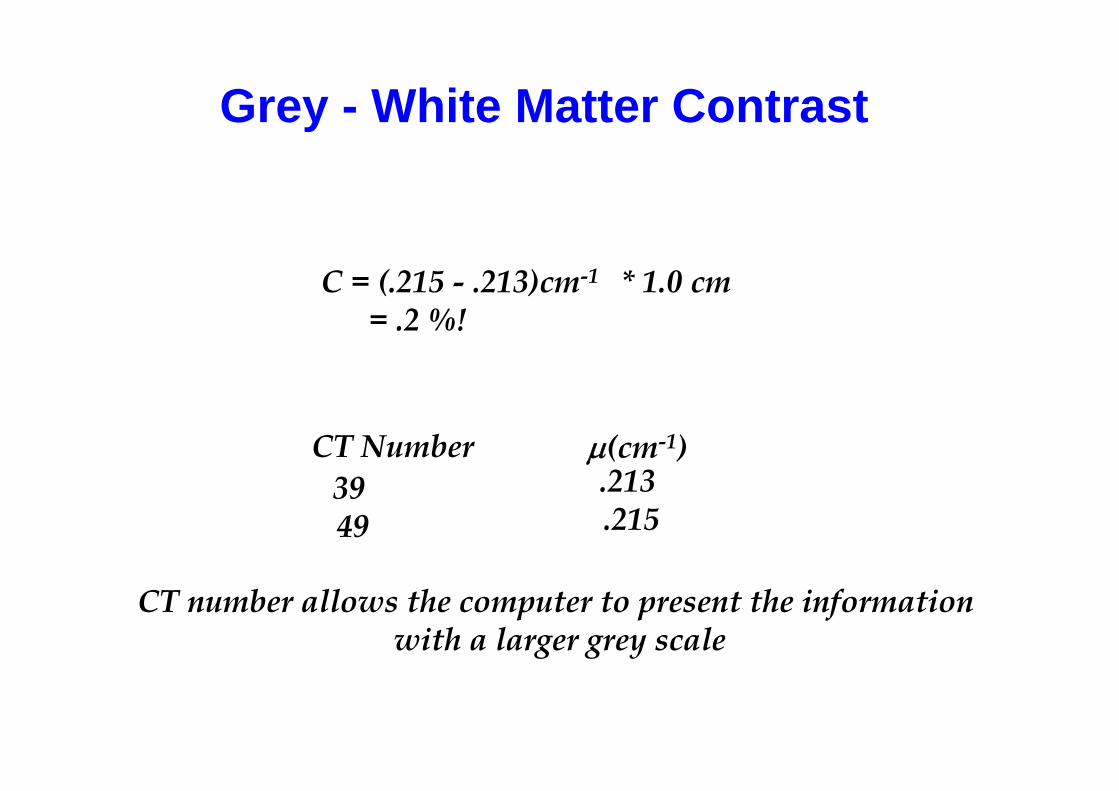
Grey - White Matter Contrast
C = (.215 - .213)cm-1 * 1.0 cm = .2 %!
CT Number µ(cm-1)39 49
.213 .215
CT number allows the computer to present the informationwith a larger grey scale
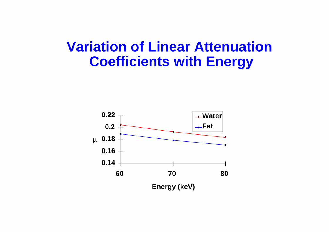
Variation of Linear AttenuationCoefficients with Energy
0.140.160.180.2
0.22
60 70 80
Energy (keV)
µ
WaterFat
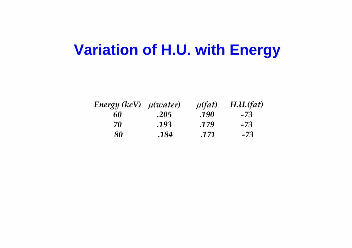
Variation of H.U. with Energy
Energy (keV) 60 70 80
µ(water) .205 .193 .184
µ(fat) .190 .179 .171
H.U.(fat) -73 -73 -73
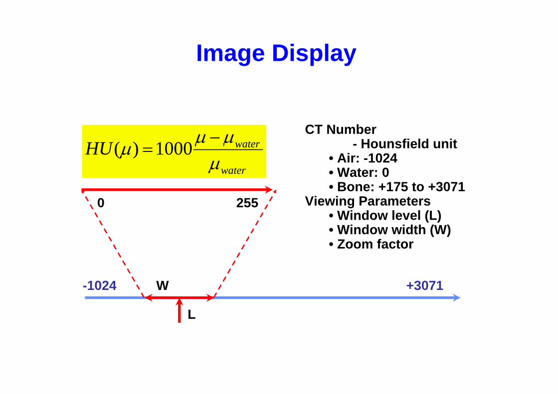
Image Display
CT Number- Hounsfield unit
• Air: -1024 • Water: 0 • Bone: +175 to +3071
Viewing Parameters • Window level (L) • Window width (W)• Zoom factor
water
waterHUµµµµ −
=1000)(
-1024 +3071
0 255
W
L
Computed Tomography Principles
• 1. Projection measurement
• 2. Scanning modes
• 3. Scanner systems
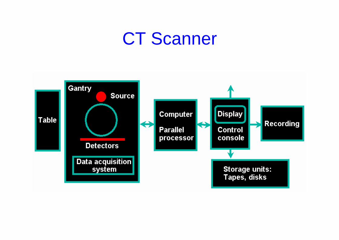
CT Scanner
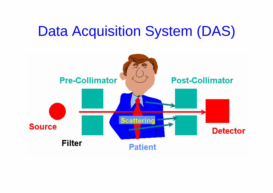
Data Acquisition System (DAS)
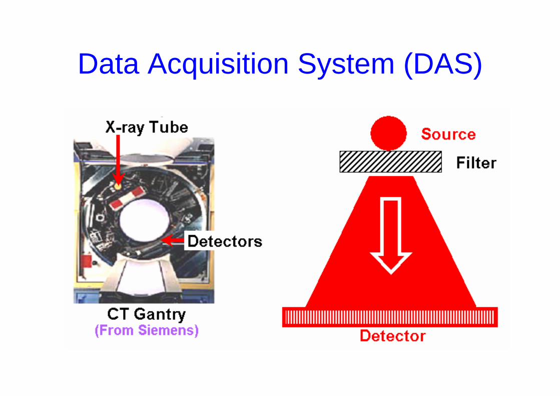
Data Acquisition System (DAS)
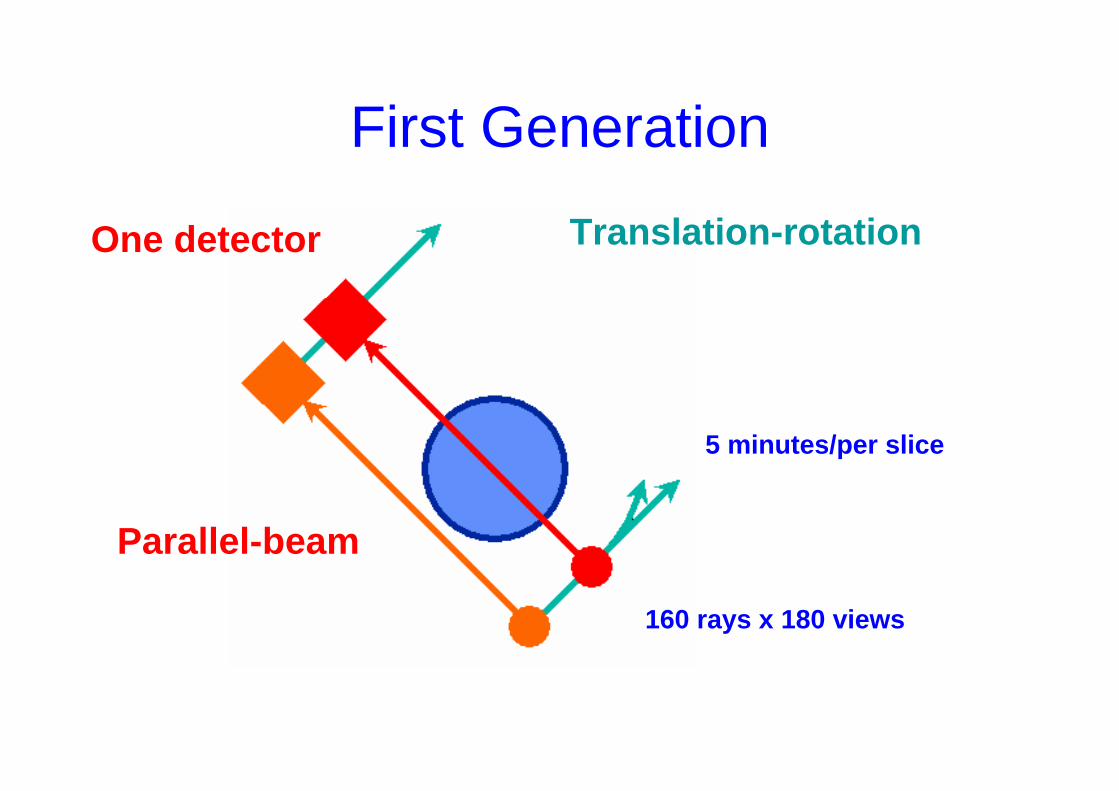
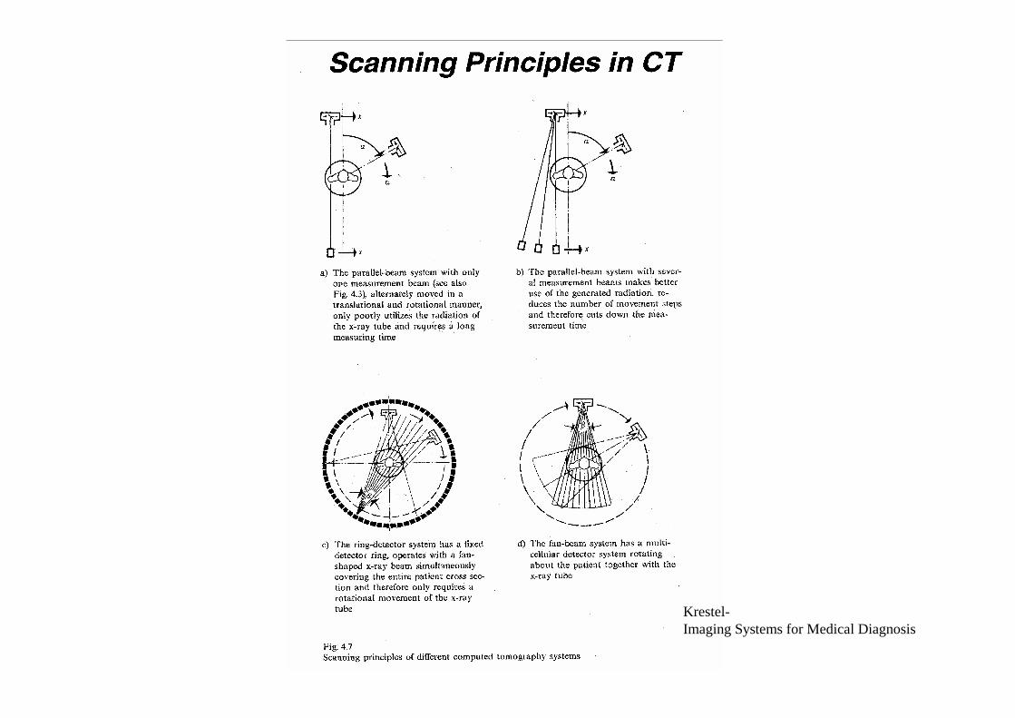
First Generation
One detector Translation-rotation
Parallel-beam
160 rays x 180 views
5 minutes/per slice
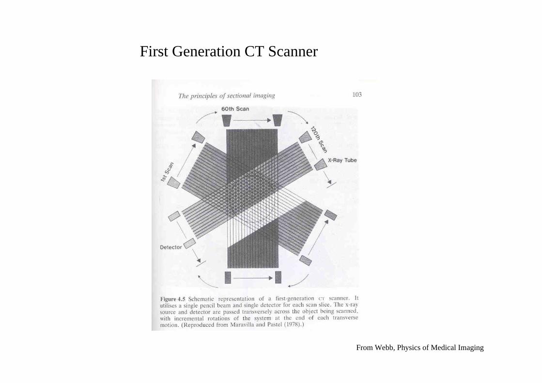
First Generation CT Scanner
From Webb, Physics of Medical Imaging
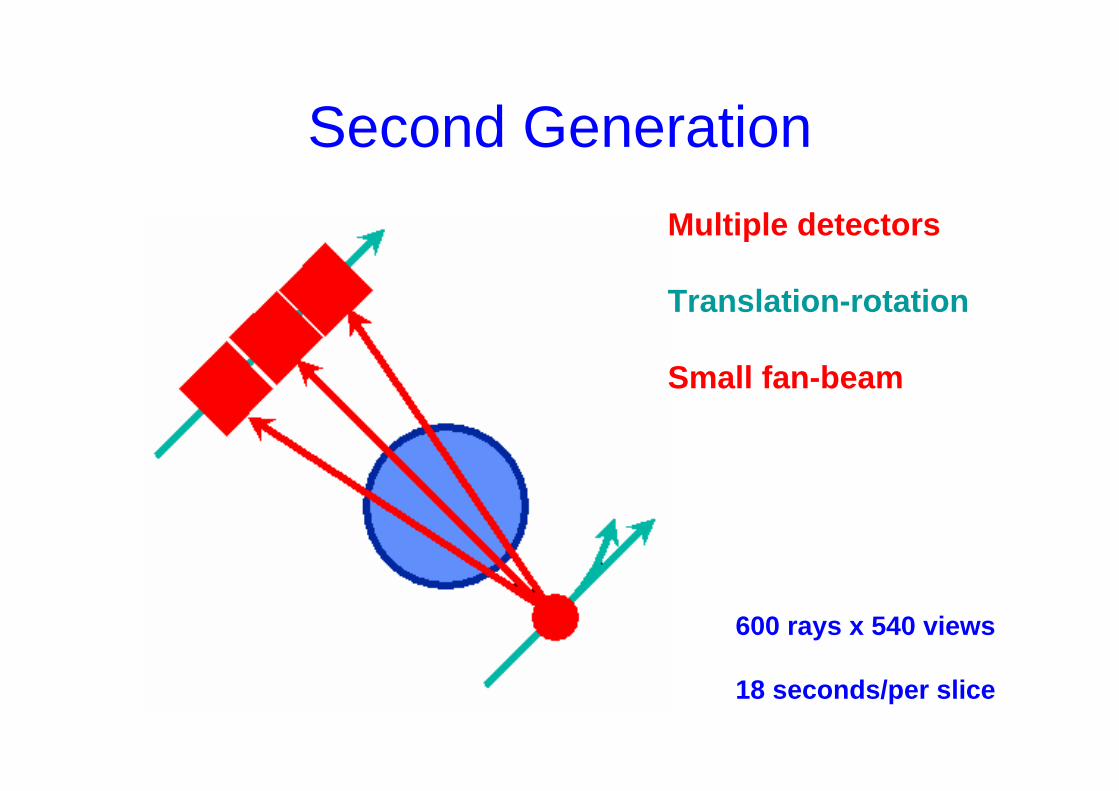
Second GenerationMultiple detectors
Translation-rotation
Small fan-beam
600 rays x 540 views
18 seconds/per slice
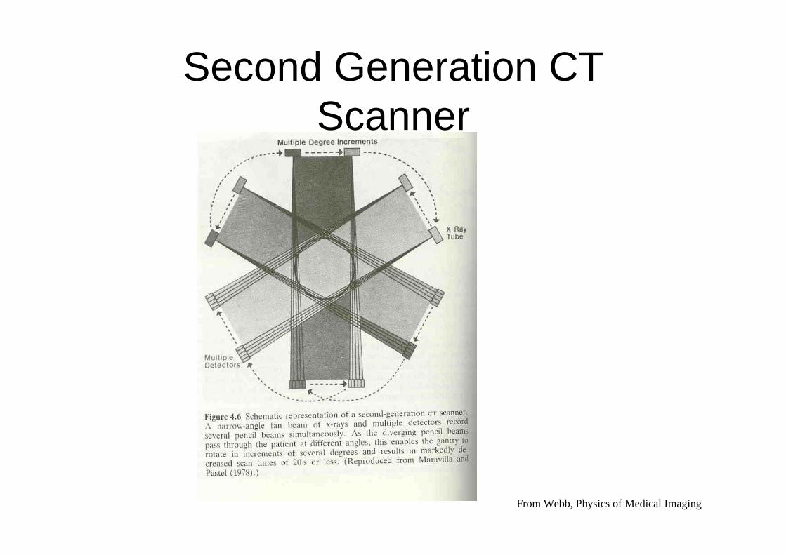
Second Generation CT Scanner
From Webb, Physics of Medical Imaging
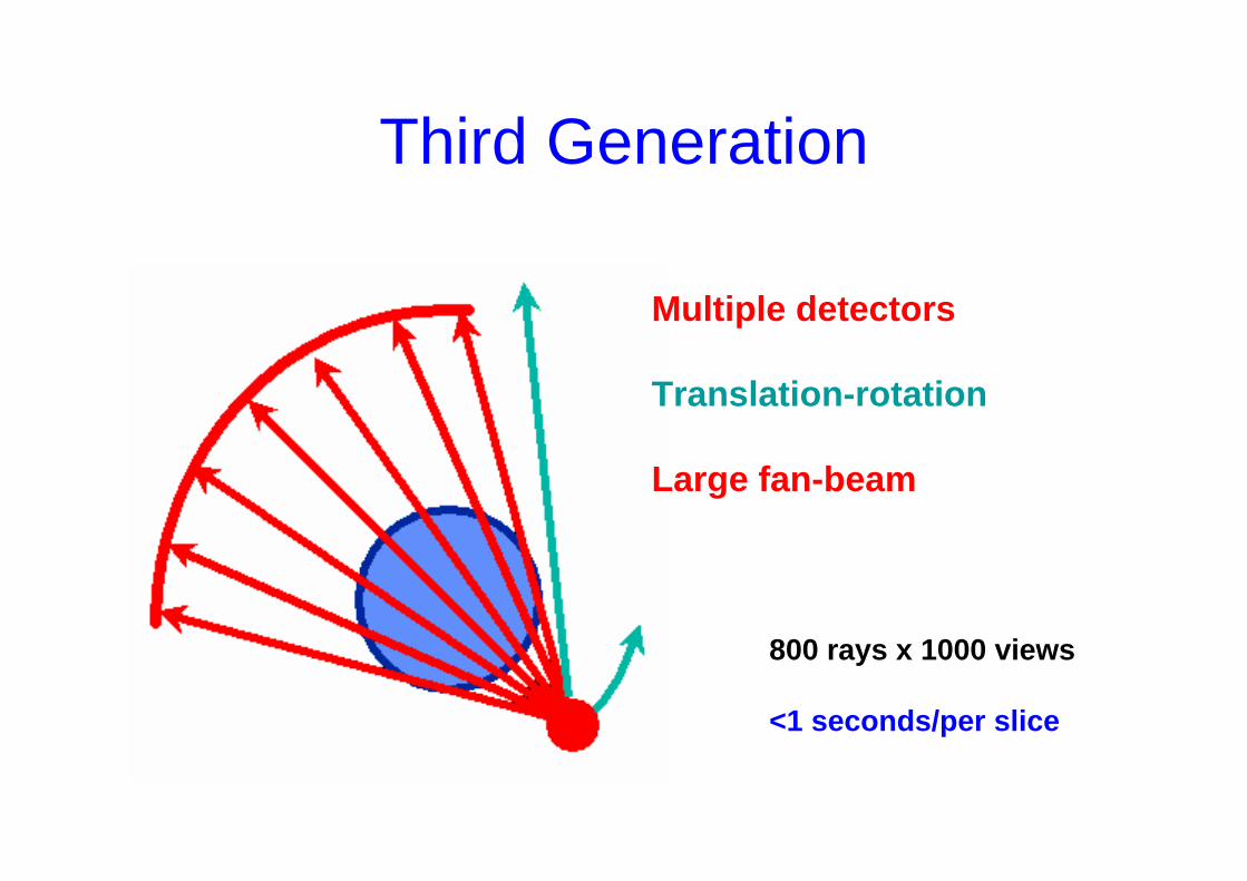
Third Generation
Multiple detectors
Translation-rotation
Large fan-beam
800 rays x 1000 views
<1 seconds/per slice
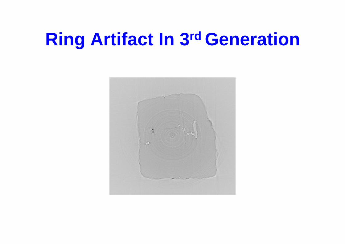
Ring Artifact In 3rd Generation
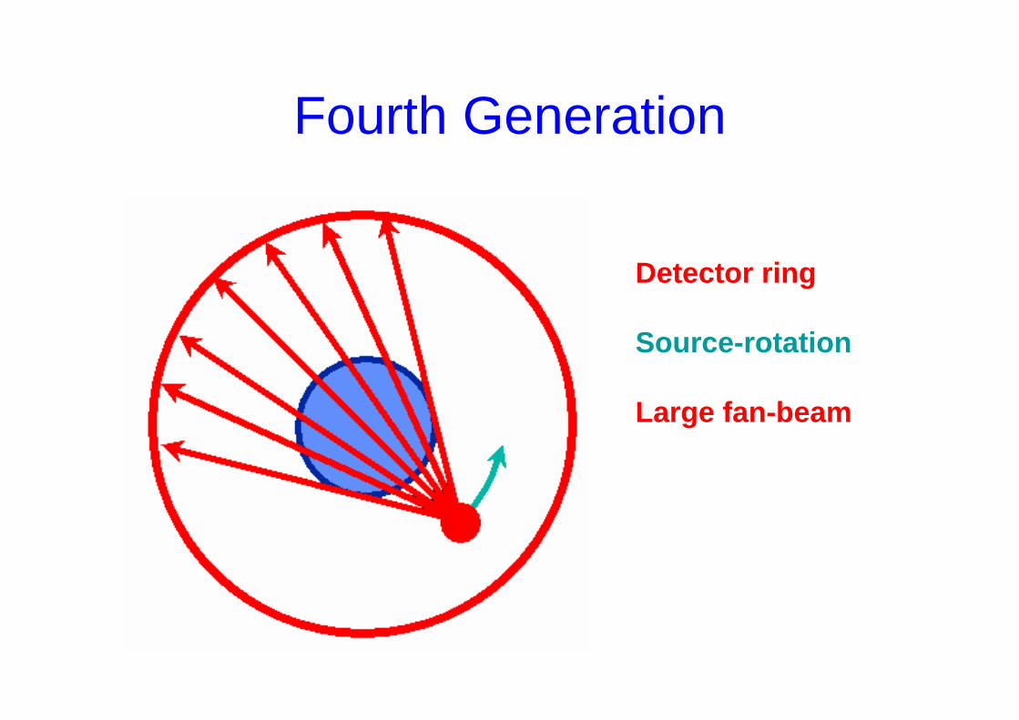
Fourth Generation
Detector ring
Source-rotation
Large fan-beam
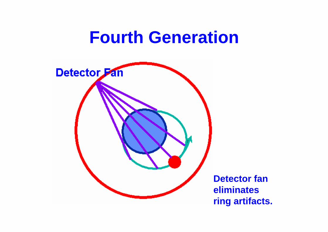
Fourth Generation
Detector fan eliminatesring artifacts.
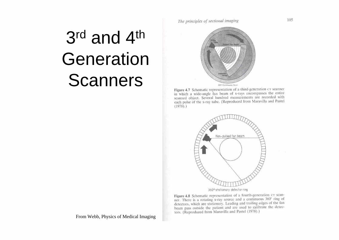
3rd and 4th
Generation Scanners
From Webb, Physics of Medical Imaging
Krestel-Imaging Systems for Medical Diagnosis
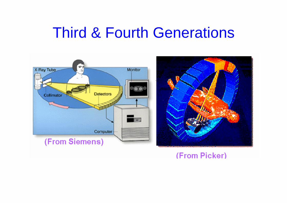
Third & Fourth Generations
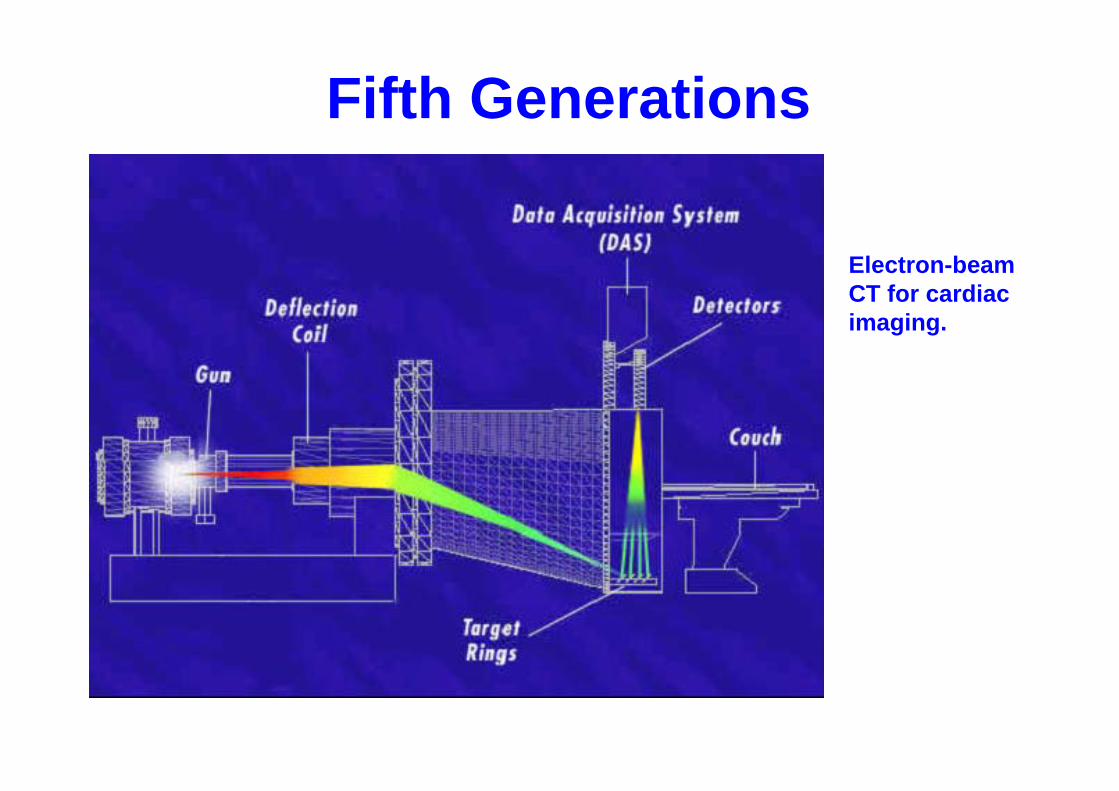
Fifth Generations
Electron-beamCT for cardiac imaging.
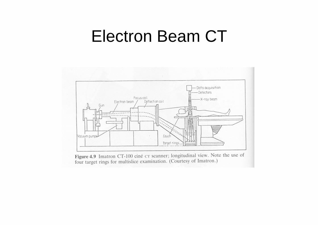
Electron Beam CT
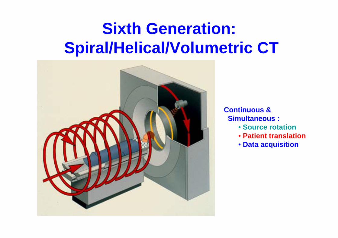
Sixth Generation: Spiral/Helical/Volumetric CT
Continuous &Simultaneous :
• Source rotation • Patient translation• Data acquisition
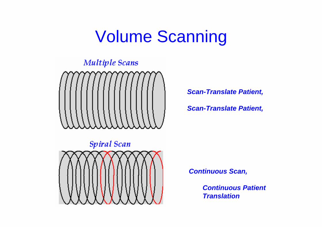
Volume Scanning
Scan-Translate Patient,
Scan-Translate Patient,
Continuous Scan,
Continuous PatientTranslation
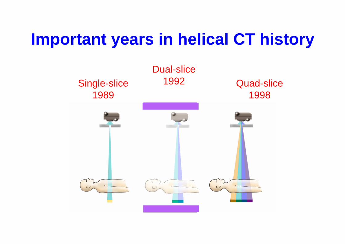
Important years in helical CT history
Single-slice1989
Dual-slice1992 Quad-slice
1998
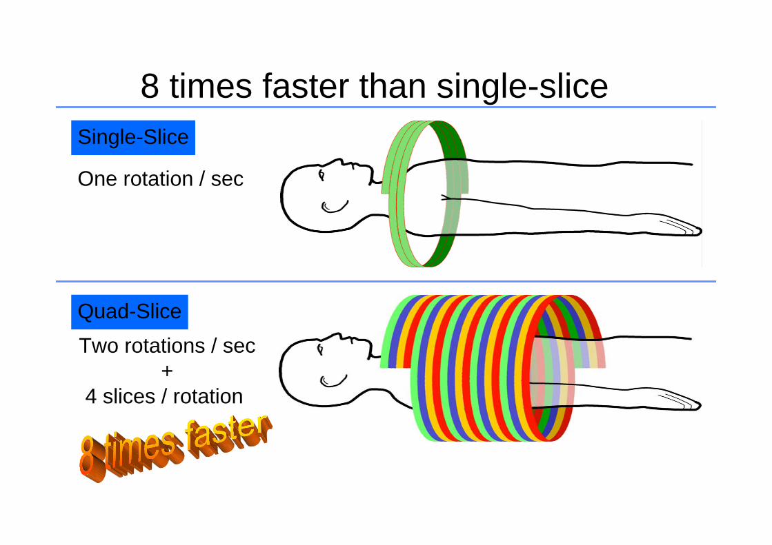
Quad-Slice
Single-Slice
8 times faster than single-slice
One rotation / sec
Two rotations / sec +
4 slices / rotation
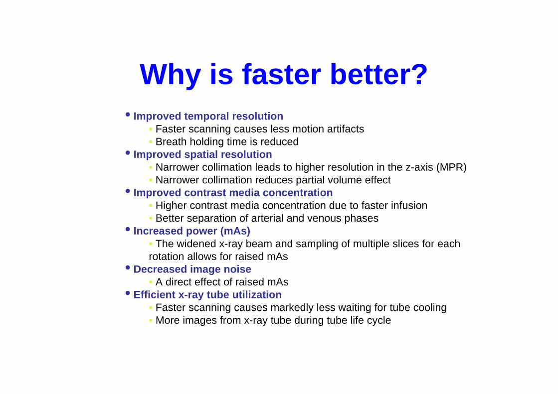
Why is faster better?• Improved temporal resolution
• Faster scanning causes less motion artifacts• Breath holding time is reduced
• Improved spatial resolution• Narrower collimation leads to higher resolution in the z-axis (MPR) • Narrower collimation reduces partial volume effect
• Improved contrast media concentration• Higher contrast media concentration due to faster infusion• Better separation of arterial and venous phases
• Increased power (mAs)• The widened x-ray beam and sampling of multiple slices for eachrotation allows for raised mAs
• Decreased image noise• A direct effect of raised mAs
• Efficient x-ray tube utilization• Faster scanning causes markedly less waiting for tube cooling • More images from x-ray tube during tube life cycle
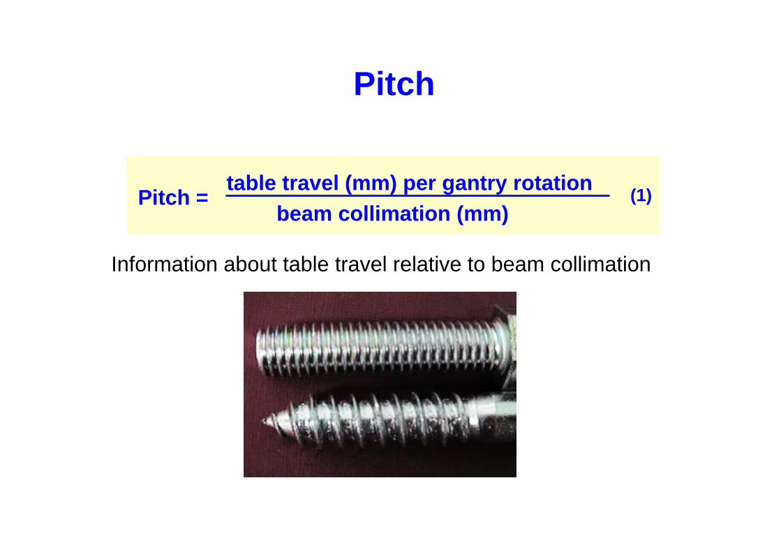
Pitch
Pitch = (1)table travel (mm) per gantry rotationbeam collimation (mm)
Information about table travel relative to beam collimation
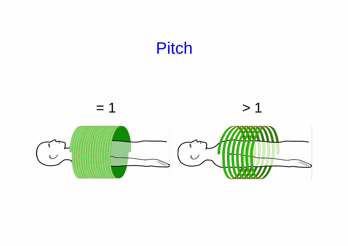
> 1= 1
Pitch
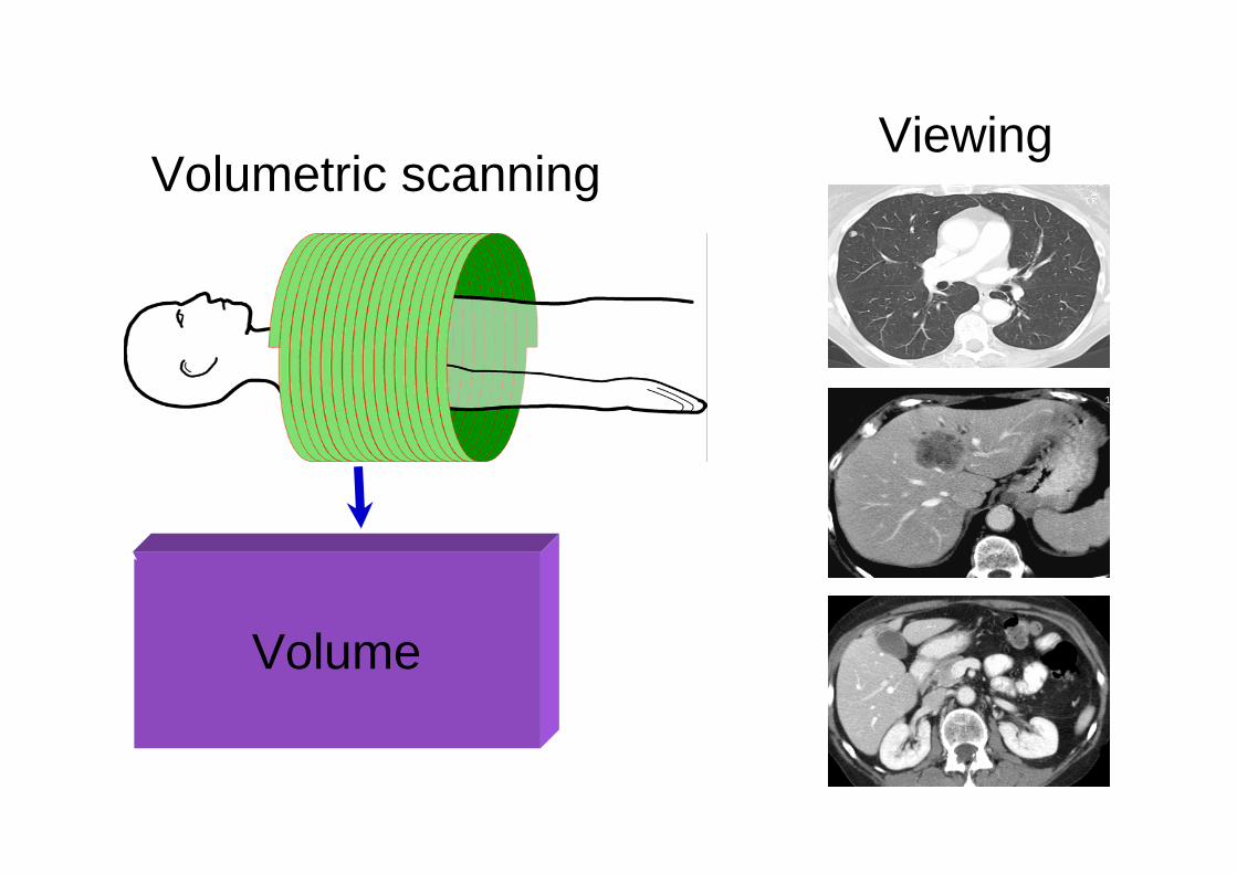
Volume
Volumetric scanningViewing
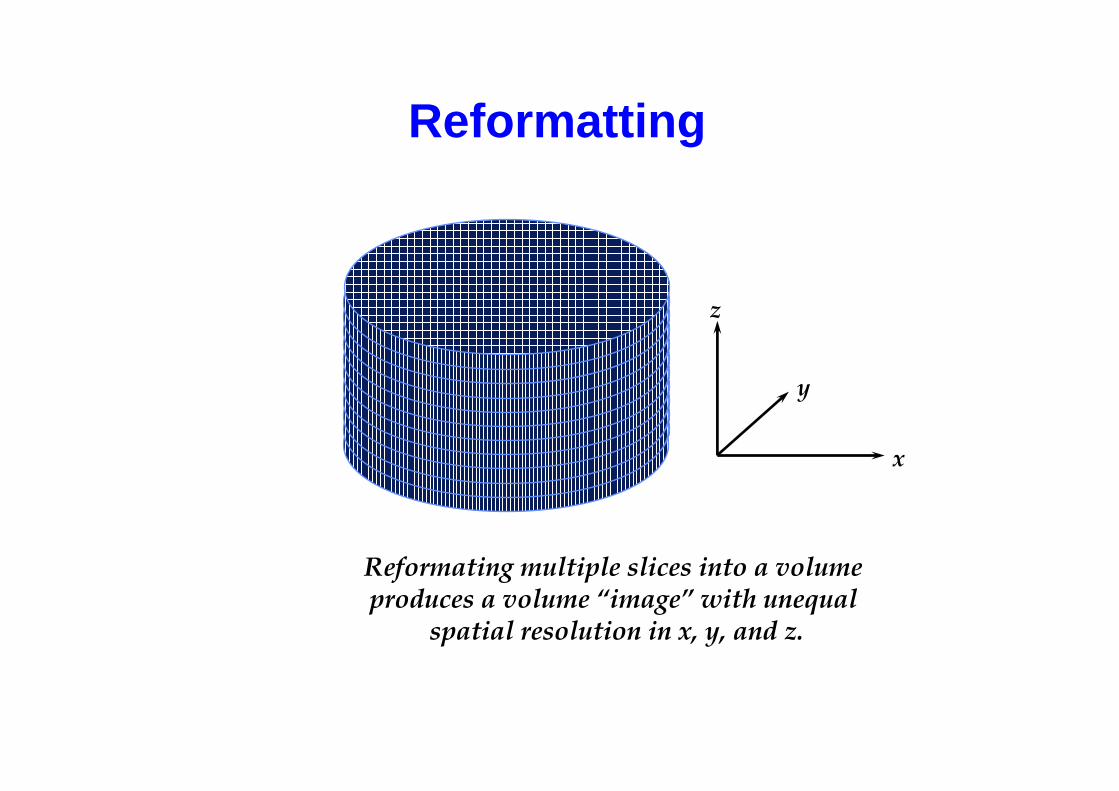
Reformatting
x
y
z
Reformating multiple slices into a volume produces a volume “image” with unequal
spatial resolution in x, y, and z.
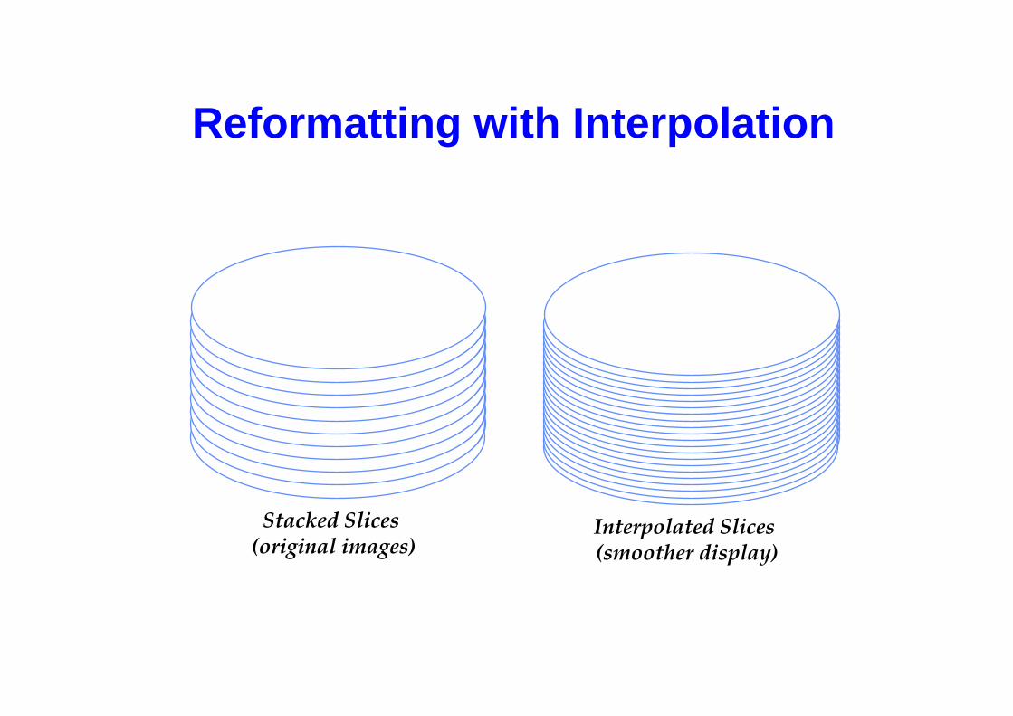
Reformatting with Interpolation
Stacked Slices(original images)
Interpolated Slices(smoother display)
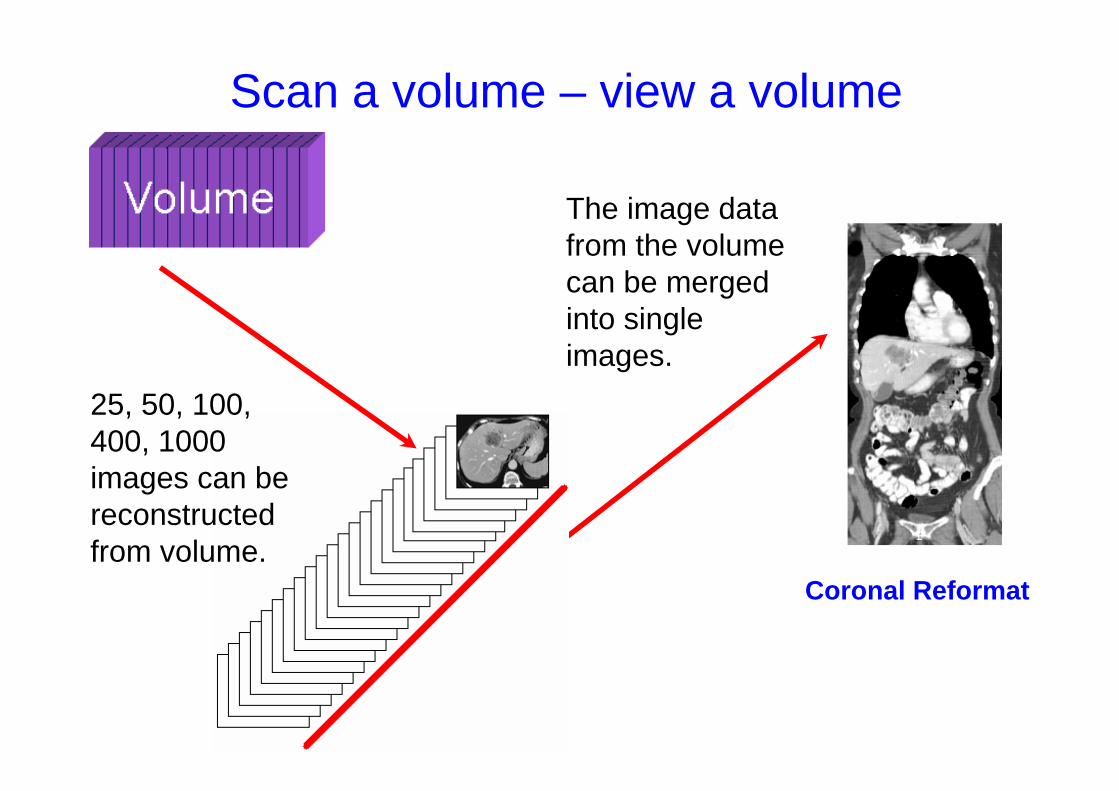
Scan a volume – view a volume
The image data from the volume can be mergedinto single images.
Coronal Reformat
25, 50, 100, 400, 1000 images can bereconstructedfrom volume.