Final Report on NavBot - University of Florida€¦ · Final Report on NavBot ... 5.1 High-torque...
22
Final Report on NavBot * Kosala Kodikara Prof. Arroyo , Prof. Schwartz TASS: William Dubel ,Max Koessik Intelligent Machines Design Laboratory University of Florida Gainesville, Florida 32603 [email protected] August 9, 2004 Abstract This paper is about a complete design and construction of a navigating robot called NavBot. * Formatted using L A T E X2 ε 1
Transcript of Final Report on NavBot - University of Florida€¦ · Final Report on NavBot ... 5.1 High-torque...
Final Report on NavBot ∗
Kosala Kodikara
Prof. Arroyo , Prof. Schwartz
TASS: William Dubel ,Max Koessik
Intelligent Machines Design Laboratory
University of Florida
Gainesville, Florida 32603
August 9, 2004
Abstract
This paper is about a complete design and construction of a navigating robot called
NavBot.
∗Formatted using LATEX2ε
1

Contents
1 Executive summary 4
2 Introduction 5
3 Integrated System 5
4 Mobile Platform 6
4.1 20x4 LCD Display with LED Back light . . . . . . . . . . . . . . . . . . . . 8
4.2 Wood Platform . . . . . . . . . . . . . . . . . . . . . . . . . . . . . . . . . . 8
5 Actuation 9
5.1 High-torque Ball-bearing Servo Motor . . . . . . . . . . . . . . . . . . . . . . 9
5.2 Injection Molded Wheels . . . . . . . . . . . . . . . . . . . . . . . . . . . . . 9
6 Sensors 9
6.1 Sharp GP2Y0A02YK Distance Measuring Sensor . . . . . . . . . . . . . . . 9
6.2 Shaft Encoder . . . . . . . . . . . . . . . . . . . . . . . . . . . . . . . . . . . 11
6.3 Devantech CMPS03 Digital Compass . . . . . . . . . . . . . . . . . . . . . . 11
6.4 Bump Sensor . . . . . . . . . . . . . . . . . . . . . . . . . . . . . . . . . . . 13
6.5 High Speed Low-Cost Transceivers - 2.4GHz with Built-In Antenna . . . . . 13
6.6 Base Station . . . . . . . . . . . . . . . . . . . . . . . . . . . . . . . . . . . . 15
7 Behaviors 15
8 Experimental Layout and Results 15
9 Conclusion 16
10 Future Work 17
11 Documentation 17
11.1 Circuits . . . . . . . . . . . . . . . . . . . . . . . . . . . . . . . . . . . . . . 17
11.2 Software . . . . . . . . . . . . . . . . . . . . . . . . . . . . . . . . . . . . . . 18
2

12 Acknowledgements 21
3

1 Executive summary
The navbot is as simple wall following room mapping robot . The robot will find a wall
and follow it to the edge then turn accordingly and after some time it will stop and relay
its messages back . The messages will transmitted the user or read from a serial port. The
messages will primarily consist of how many ticks that have been registered from the shaft
encoder. The average compass measurement will also be relayed.
4

2 Introduction
This paper is about a complete design and construction of a navigating Robot. The robot
is designed bottom up from scratch. The purpose of the robot as said is to map a small
room and possibly a small object in it. The robot will send information back to the user.
A navigating robot is of a special interest to robotics to study because that it is the basic
function an efficient robot must master. Navigating can be broken down to several key
aspects they are: The ability to move from one place to another ,to know how to get to a
specific location or better yet to discover a path to get to a specific location ,knowing where
it is going, to know when it has got to its intended location, to know how to get to the
location again, possibly with a better path to destination and to tell some one else it has
got there and how so.
To accomplish all what is said above would be above and beyond me due to the fact that
I am Computer Science graduate Student.Therefore, I have no prior experience in building
robots or even electronic circuits. I have no skills in terms of soldering or telling one electronic
wire from another. So I will try to accomplish small subset of it. The objectives of the Navbot
in this case would be kept simple as possible .
3 Integrated System
The robot was built around the MAVRIC II Atmega 128 micro controller (1). I planed
to use five sensors and a separate base station for my robot design. The five sensors will be
a compass , three IRs , two bump switches , one shaft encoder and one transceiver. The
robot will communicate with a base station via the transceiver. The base station it self will
consist of a micro-controller , transceiver and a USB port to the PC.
5

Figure 1: NavBot.
4 Mobile Platform
Figures 2,3 and 4 shows the fully assembled robot platform . The platform was built using
wood. The design was made in AutoCAD and milled out using the T-TECH machine in the
IMLD lab.
Figure 2: NavBot.
6

Figure 3: NavBot.
Figure 4: NavBot.
7
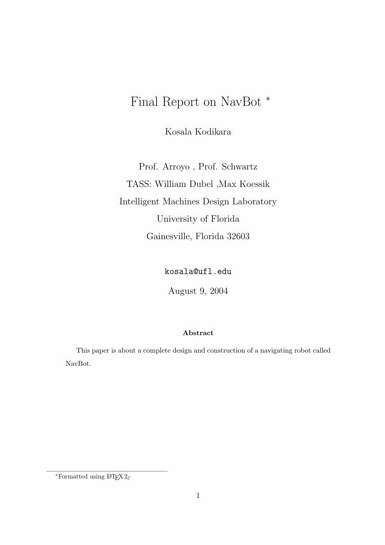
4.1 20x4 LCD Display with LED Back light
Figure 5: HD44780U LCD.
The LCD (figure.5) consist of a HD44780U dot matrix liquid crystal display controller
and driver LSI displays alphanumeric, Japanese kana characters, and symbols. It can be
configured to drive a dot-matrix liquid crystal display under the control of a 4- or 8-bit
microprocessor. Since all the functions such as display RAM, character generator, and
liquid crystal driver, required for driving a dot-matrix liquid crystal display are internally
provided on one chip, a minimal system can be interfaced with this controller/driver. A single
HD44780U can display up to one 8-character line or two 8-character lines. The HD44780U
has pin function compatibility with the HD44780S which allows the user to easily replace
an LCD II with an HD44780U. The HD44780U character generator ROM is extended to
generate 208 5 8 dot character fonts and 32 5 10 dot character fonts for a total of 240
different character fonts. The low power supply (2.7V to 5.5V) of the HD44780U is suitable
for any portable battery-driven product requiring low power dissipation.
4.2 Wood Platform
8

5 Actuation
Figure 6: High-torque Ball-bearing Servo Motor.
5.1 High-torque Ball-bearing Servo Motor
The robot will be using a pair of BP148X 2BB High-torque Ball-Bearing servo motors
(figure.6) . This motor generates more than 69 oz.in. of torque at 4.8 Volts, compared
to the ”standard” servo motor torque of 47 oz.in. It Has two ball bearings.
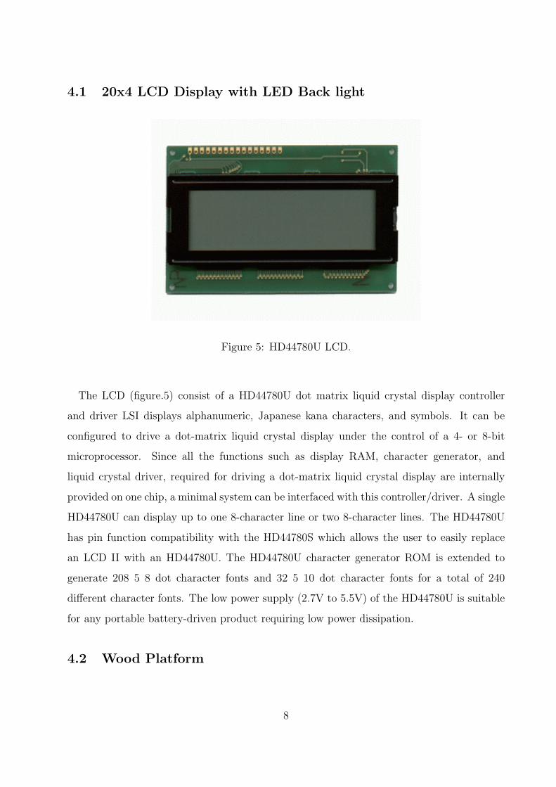
5.2 Injection Molded Wheels
The molded-in spline (figure.7) is designed to fit the servo.
6 Sensors
6.1 Sharp GP2Y0A02YK Distance Measuring Sensor
This is the long-range version of the popular GP2D12 infrared distance measuring sensor
(figure.8). Accurately determines range to target between 20cm and 150cm. Can be used as
a proximity detector to detect objects between 0cm and 250cm.
9
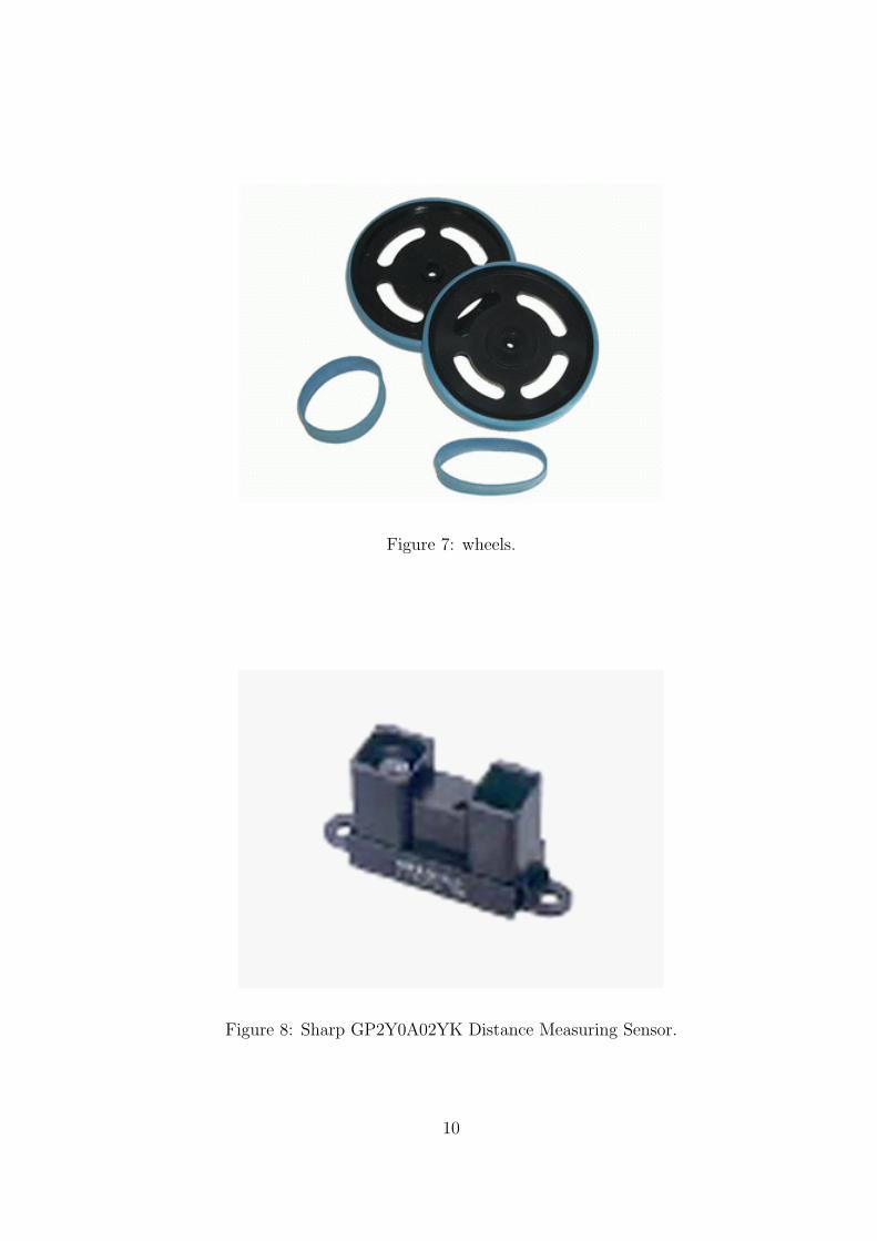
Figure 7: wheels.
Figure 8: Sharp GP2Y0A02YK Distance Measuring Sensor.
10

6.2 Shaft Encoder
Figure 9: Hamamatsu P5587 IR Photoreflector.
The shaft encoder is built using a Hamamatsu P5587 IR Photoreflector (figure.9). This
Tiny infrared photoreflector often used for wheel position encoders. Internal amplifier and
Schmitt Trigger output make it ideal for interfacing to a digital input with minimal external
components.
Figure 10 shows the fully constructed shaft encoder.
6.3 Devantech CMPS03 Digital Compass
This compass module (figure.11) has been specifically designed for use in robots as an
aid to navigation. The compass uses two Philips KMZ51 magnetic field sensors, which are
sensitive enough to detect the Earth’s magnetic field. The two sensors are mounted at right
angles to each other; the CMPS03 module uses this information to compute the direction of
the horizontal component of the Earth’s magnetic field to within 0.1 degree with an accuracy
of 3-4 degrees. The CMPS03 outputs a unique number to represent the direction the robot
is facing.
11

Figure 10: Shaft encoder attached to the servo.
Figure 11: Devantech CMPS03 Digital Compass.
12

6.4 Bump Sensor
Bump sensors were made out of two TMCGS40 spaciality switches.
6.5 High Speed Low-Cost Transceivers - 2.4GHz with Built-In
Antenna
Figure 12: High Speed Low-Cost Transceivers - 2.4GHz with Built-In Antenna.
2.4 GHz transceiver modules (figure.12) with built in antenna designed around the Nordic
Semiconductor nRF2401. They incorporate a buffer that is loaded at any clock speed, once
the transmit bit is set, all data is shot towards the receiving module at 1 million bytes per
second. Once the data has been successfully received by the other side, the data can be
clocked out of the receive buffer at any rate. This drastically reduces current consumption
by minimizing the time in active transmit mode.
The transceiver requires 3.3v on all I/O. Figure.13 provides the proper voltage level trans-
lation.
13

Figure 13: Voltage level translator with built in voltage regulator.
Figure 14: Base Station which will be hooked up to a PC.
14

6.6 Base Station
For the base station I used the ATmega 8535 with USB support development board from
[1] . The final construction is shown in figure 14. To use the USB, the driver need to be
installed (the USB chip is from FTDI and the driver can be obtained from [5]) and it will
show up as another serial port.
BaseStation outputs information via USB to the PC .The PC takes the infomation and
process it through a custom made Java application and then draws a map.
7 Behaviors
The behavior is simple . The Robot goes around a simple room mapping its dimensions
and then relaying information back to the PC. When it hits a simple object it will map it
as well.
8 Experimental Layout and Results
The robot was built one system at a time. First the LCD was integrated into the robot
using [3] code. Some modification was required for this code,it worked like a charm. Then
the IR was integrated using [4] code. Some modification was also required for this code
as well. The IR worked perfectly as well. The compass integration took a while . This
because of a faulty wiring the compass gave no output later the problem was found and
fixed . The code for this also came from [4] . The compass and the IR does give fluctuating
values . I averaged them out over time to get a more consistent value. The shaft encoder
was designed iteratively number of times. It functions perfectly albeit with not so accurate
wheel pattern.It is hooked up to the PORTE interrupt pins . The bump switch is a simple
switch design. I did not hook it up to the interrupt instead I am polling it. I had some
problem with the servo code that I initially got from Will. After Unsuccessfully trying it
out I designed my own.It works real well.
15

The Navbot keeps track of it previous actions to make a calculation on future actions .
Due to lack of memory not much of a stack of information is kept. The Navbot also will
make path trajectory corrections with the aid of the compass. This will keep it going strait.
9 Conclusion
The experimental results were not as good as expected. It had some glaring failures.
The robot went around the room,albeit oscillatory straitness . This was primarily due to
the servo inconsistencies. Alas it seems no two servos are alike. Navbot failed to relay
information back to the PC. This was primarily due to the fact that the robots’ transceiver
did not function as expected. what was to be a simple transceiver turned out to me much
more complicated. The transceiver needed information clocked in and also specific voltage to
activate . The information was later clocked in using a micro-controller and a special switch
was made for the voltage translation. It still did not function . I suspect that the transceiver
burned out in an earlier experiment. Navbot did successfully avoid collisions and figure out
distances. On the base station side the USB was a success but since the transceiver didn’t
work .So I used it instead to output Navbot via UART. It worked perfectly for that.
Simple as the concept may sound, a Navigating robot that communicates with a PC,
became to be a very complex and difficult problem . I only managed to do part of it. I hope
to complete it on my spare time. I have learned more in this class than I have in any other
class I have ever taken. I learned to use AutoCAD, Protel, DXP ,EagleCAD and ISOPro.
I learned to solder surface mounts and complex circuitry. I also learned many Electrical
Engineering principals. Even though I knew some Electrical Engineering concepts. I never
really applied them in the real world. It was a baptism with fire when it came to Electronics.
I probably burned more than $150 worth of electronics. Nevertheless , the practical hands
on training I got from this class will be invaluable for me in years to come. As I come close
to the end of my Masters and probably my school life , this class would be the class that I
remmber the most. Audiu to all !
16

10 Future Work
I would further work on my robot. I would make the transceiver work and also add
more enhancements and intelligence to the robot. I would try out some adaptive behavior
algorithms. Given the chance I would do lot better on a project like this because when I
started I knew nothing. Therefore, it would be significant improvement if I were to-do the
robot again.
11 Documentation
11.1 Circuits
Figure 15: 3.3V voltage regulator plus voltage translator from Texas Instruments.
All the following PCBs were designs using EagleCAD.
1. Figure.17 shows the 5.0V Voltage regulator PCB design . This regulator gives two
stable outputs . One for the Sensors and the other to the servos.
17

Figure 16: LCD contrast adjuster plus 5.0V regulated power extender.
2. Figure.15 shows the 3.3V Voltage regulator I/O for the transceiver . It will translate
5.5V to 3.3V and 3.3V to 5.5V.
3. Figure. 16 shows the contrast controller for the LCD. It also extends a regulated
output.
4. Figure. 18 shows the wheel encoder.
11.2 Software
I used AVR GCC 3.4 to generate the code. I got the compiler from WinAVR and AVR
studio was used to programm the Atmega 128.
The Java App was made using JDK 1.4.2 and JBUILDER 7.
The software will be available from my website http://grove.ufl.edu/k̃osala.
18
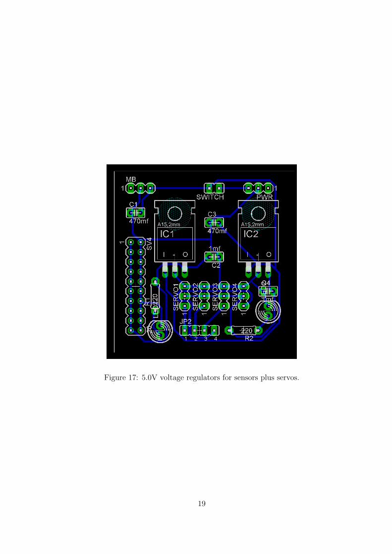
Figure 17: 5.0V voltage regulators for sensors plus servos.
19
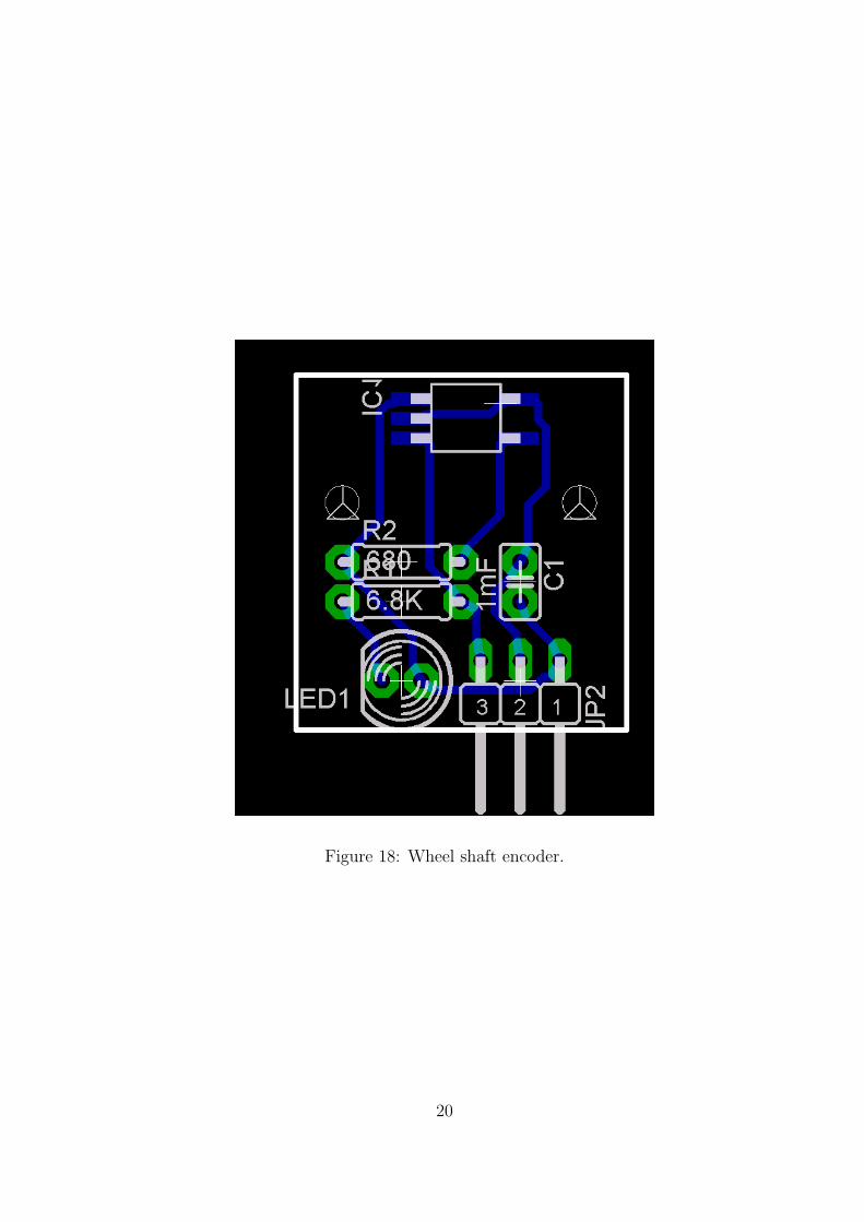
Figure 18: Wheel shaft encoder.
20

12 Acknowledgements
I like to thank Max and Will for their invaluable help. I think I cut the most PCBs ever
. So Here is a big Thanks to the TAs! . Dr. Arroyo for his guidance and Dr. Schwartz for
his discipline. Also I like to thank Jim, Danny, Jay , Allen , Tuan and Salman. Also, rest of
the guys at IMDL and MIL, big cheers to ALL! . Thanks for the help guys.
21

References
[1] sparkfun, sparkfun, http://www.sparkfun.com/ ,2004.
[2] MarkIII, MarkIII, http://www.junun.org/MarkIII/ ,2004.
[3] Peter Fleury, [email protected], http://jump.to/fleury, 2004.
[4] MAVRIC II, http://www.bdmicro.com/,2004.
[5] Future technology Devices International Ltd., http://www.ftdichip.com/,2004.
22