EXTENSION OF OPTIMIZATION CAPABILITIES WITH TOSCA, ANSA … · · 2016-11-08EXTENSION OF...
9
4 th ANSA & μETA International Conference EXTENSION OF OPTIMIZATION CAPABILITIES WITH TOSCA, ANSA AND ULTRASIM™ 1 Helge Weiler * , 2 Torsten Hensel 1 BASF SE, Germany, 2 BASF SE, Germany KEYWORDS Optimization, TOSCA, ULTRASIM™, fiber reinforced plastics ABSTRACT This presentation gives an insight into the conjoint application of shape optimization and ULTRASIM™ at BASF using ANSA as preprocessing tool. Thermoplastic materials, especially if they are reinforced with short glass fibers, show some special mechanical properties that differentiate them from metals. There is tension- compression asymmetry, dependency on temperature, humidity (in case of Polyamide) and strain rate, and, depending on the fraction of fiber reinforcement, an increasing anisotropy caused by fiber orientation and orientation distribution. To precisely predict the performance of structural parts made of those materials, those properties have to be taken into account in simulation. As fiber orientation and orientation distribution is a result of the injection molding process, this process has to be simulated and taken into account for subsequent mechanical analyses. Experience shows that the accurate prediction of the part behaviour is not possible with classical methods used for metals. BASF ULTRASIM™ is a simulation environment that takes the above described properties into account: The fiber distribution obtained by process simulation is taken into account to form a specific material law for every finite element of the structural simulation model. An energy based failure model allows the precise prediction of load level and –location in the part. ULTRASIM™ can be used with many of the established commercial FE-solvers. Data exists for a big range of BASF thermoplastics. Structural parts often show “load spots”, e.g. in the area of notches, diameter changes and so on. Local shape optimization is an established tool for the reduction of those spots. One of the most common shape optimization software is TOSCA.shape, which uses a homogenization approach. To be applicable in daily work, advanced methods like ULTRASIM™ and shape optimization have to integrate tightly in standard simulation tools. At BASF, a fast and continuous simulation setup is provided by using ANSA for both standard preprocessing and optimization setup. The presentation motivates the general problems and challenges and gives examples for first successful use of the ANSA/Tosca/ULTRASIM™ Workflow. 1. INTRODUCTION The BASF CAE philosophy is based on two pillars, called “Simulate the part right”, and “Simulate the right part”. The first pillar means to consider local material properties as precisely as necessary. One consequence for parts made of short fiber reinforced plastics is to determine the fiber orientation first, and to map a material definition on the mechanics model that takes the orientation as well as the special characteristics of thermoplastic materials into account. The second pillar starts earlier and means that we want to help our customers to find a design that fulfils the demands as good as possible. Here, a key element is structural simulation coupled with numerical optimization. As well as linear topology optimization, parameter optimization of highly nonlinear problems by means of a morphing (ANSA) – optimizing – evaluating (META) loop is well established. Recently, our optimization portfolio
Transcript of EXTENSION OF OPTIMIZATION CAPABILITIES WITH TOSCA, ANSA … · · 2016-11-08EXTENSION OF...
4th
ANSA & μETA International Conference
EXTENSION OF OPTIMIZATION CAPABILITIES WITH TOSCA, ANSA AND ULTRASIM™ 1Helge Weiler*, 2Torsten Hensel 1BASF SE, Germany, 2BASF SE, Germany KEYWORDS Optimization, TOSCA, ULTRASIM™, fiber reinforced plastics ABSTRACT This presentation gives an insight into the conjoint application of shape optimization and ULTRASIM™ at BASF using ANSA as preprocessing tool. Thermoplastic materials, especially if they are reinforced with short glass fibers, show some special mechanical properties that differentiate them from metals. There is tension-compression asymmetry, dependency on temperature, humidity (in case of Polyamide) and strain rate, and, depending on the fraction of fiber reinforcement, an increasing anisotropy caused by fiber orientation and orientation distribution. To precisely predict the performance of structural parts made of those materials, those properties have to be taken into account in simulation. As fiber orientation and orientation distribution is a result of the injection molding process, this process has to be simulated and taken into account for subsequent mechanical analyses. Experience shows that the accurate prediction of the part behaviour is not possible with classical methods used for metals. BASF ULTRASIM™ is a simulation environment that takes the above described properties into account: The fiber distribution obtained by process simulation is taken into account to form a specific material law for every finite element of the structural simulation model. An energy based failure model allows the precise prediction of load level and –location in the part. ULTRASIM™ can be used with many of the established commercial FE-solvers. Data exists for a big range of BASF thermoplastics. Structural parts often show “load spots”, e.g. in the area of notches, diameter changes and so on. Local shape optimization is an established tool for the reduction of those spots. One of the most common shape optimization software is TOSCA.shape, which uses a homogenization approach. To be applicable in daily work, advanced methods like ULTRASIM™ and shape optimization have to integrate tightly in standard simulation tools. At BASF, a fast and continuous simulation setup is provided by using ANSA for both standard preprocessing and optimization setup. The presentation motivates the general problems and challenges and gives examples for first successful use of the ANSA/Tosca/ULTRASIM™ Workflow. 1. INTRODUCTION The BASF CAE philosophy is based on two pillars, called “Simulate the part right”, and “Simulate the right part”. The first pillar means to consider local material properties as precisely as necessary. One consequence for parts made of short fiber reinforced plastics is to determine the fiber orientation first, and to map a material definition on the mechanics model that takes the orientation as well as the special characteristics of thermoplastic materials into account. The second pillar starts earlier and means that we want to help our customers to find a design that fulfils the demands as good as possible. Here, a key element is structural simulation coupled with numerical optimization. As well as linear topology optimization, parameter optimization of highly nonlinear problems by means of a morphing (ANSA) – optimizing – evaluating (META) loop is well established. Recently, our optimization portfolio
4th
ANSA & μETA International Conference
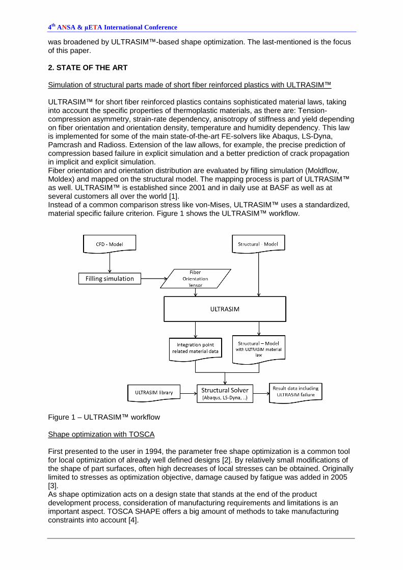
was broadened by ULTRASIM™-based shape optimization. The last-mentioned is the focus of this paper. 2. STATE OF THE ART Simulation of structural parts made of short fiber reinforced plastics with ULTRASIM™ ULTRASIM™ for short fiber reinforced plastics contains sophisticated material laws, taking into account the specific properties of thermoplastic materials, as there are: Tension-compression asymmetry, strain-rate dependency, anisotropy of stiffness and yield depending on fiber orientation and orientation density, temperature and humidity dependency. This law is implemented for some of the main state-of-the-art FE-solvers like Abaqus, LS-Dyna, Pamcrash and Radioss. Extension of the law allows, for example, the precise prediction of compression based failure in explicit simulation and a better prediction of crack propagation in implicit and explicit simulation. Fiber orientation and orientation distribution are evaluated by filling simulation (Moldflow, Moldex) and mapped on the structural model. The mapping process is part of ULTRASIM™ as well. ULTRASIM™ is established since 2001 and in daily use at BASF as well as at several customers all over the world [1]. Instead of a common comparison stress like von-Mises, ULTRASIM™ uses a standardized, material specific failure criterion. Figure 1 shows the ULTRASIM™ workflow.
Figure 1 – ULTRASIM™ workflow Shape optimization with TOSCA First presented to the user in 1994, the parameter free shape optimization is a common tool for local optimization of already well defined designs [2]. By relatively small modifications of the shape of part surfaces, often high decreases of local stresses can be obtained. Originally limited to stresses as optimization objective, damage caused by fatigue was added in 2005 [3]. As shape optimization acts on a design state that stands at the end of the product development process, consideration of manufacturing requirements and limitations is an important aspect. TOSCA SHAPE offers a big amount of methods to take manufacturing constraints into account [4].
4th
ANSA & μETA International Conference
TOSCA shape is a homogenisation approach, originally based on works of Baud [5], Neuber [6], and Schnack [7]. Iancu [8] has provided a mathematical prove for a special case. Further developments and generalisations by Sauter [9] have shown their performance in daily use. Pre-processing of optimization tasks with ANSA Until ANSA 13, pre-processing of TOSCA optimization tasks was done in a non-graphical way. Optimization specific elements of the FE model had, in general, to be defined in advance. Those are, for example: Node or element sets for design space or constraints and geometric entities for boundary conditions. Since version 13, the TOSCA pre-processing is integrated into the ANSA Task Manager. Predefined workflows, organized in trees, exist for the several optimization methods offered by TOSCA [10]. A tested FE input deck – in our case Abaqus – is the basis of the optimization task definition. This deck is imported into the Task Managers optimization tree. Now, further FE entities, like shells for geometric restrictions, node and element sets for design, constraint or mesh smoothing groups, can be defined. In the case of sets, they are written into the TOSCA input deck, while FE entities can be exported into new FE decks. The results of the optimization can directly be reimported into ANSA. In case of topology optimization, smoothing and remeshing is done in background, and the original boundary conditions are mapped onto the new mesh. For shape optimization, as the mesh structure is not changed, reimporting is even simpler. Verification runs with the new geometries can be started directly out of ANSA [11]. 3. INTEGRATED SHAPE OPTIMIZATION WITH TOSCA AND ULTRASIM™ Motivation As mentioned above, Shape optimization is a tool for local improvement of already well defined designs. The stress value chosen as optimization objective has to fulfil two basic demands: The maximum has to be located where most likely failure occurs. And its gradient in this area has to be “realistic”, meaning that the value develops equivalent to the “real” load of the part. Shape optimization usually uses von-Mises or other common comparison stresses as optimization objective. As explained in chapter 2, those are of limited use for the description of loads on plastic parts, and cannot guarantee the two main demands described above. Approach Our aim was to keep the advantages of TOSCA and ANSA, mainly the availability of geometric constraints in TOSCA and the straight forward and fast to use pre- and post-processing in ANSA. Thus, the new approach should combine those advantages with the ULTRASIM™ failure value as objective function to deliver precise failure location and -gradient. As the optimization algorithm behind TOSCA shape is not a typical sensitivity based method of mathematical programming, but a more pragmatic homogenisation approach, the effect of the optimization of the new objective function has to be verified in application. Then again, the sensitivity free algorithm allows modifications on the objective function to take place on a relatively low level. We used the fatigue interface of TOSCA to submit our results to the optimizer and replace the stress values used by default. Figure 2 shows the workflow with the necessary modifications. As surface modifications performed by shape optimization remain small, iteration wise actualisation of the fiber distribution was not necessary in our evaluations. Indeed, verification of the final result by performing a new moldflow simulation is recommended.
4th
ANSA & μETA International Conference
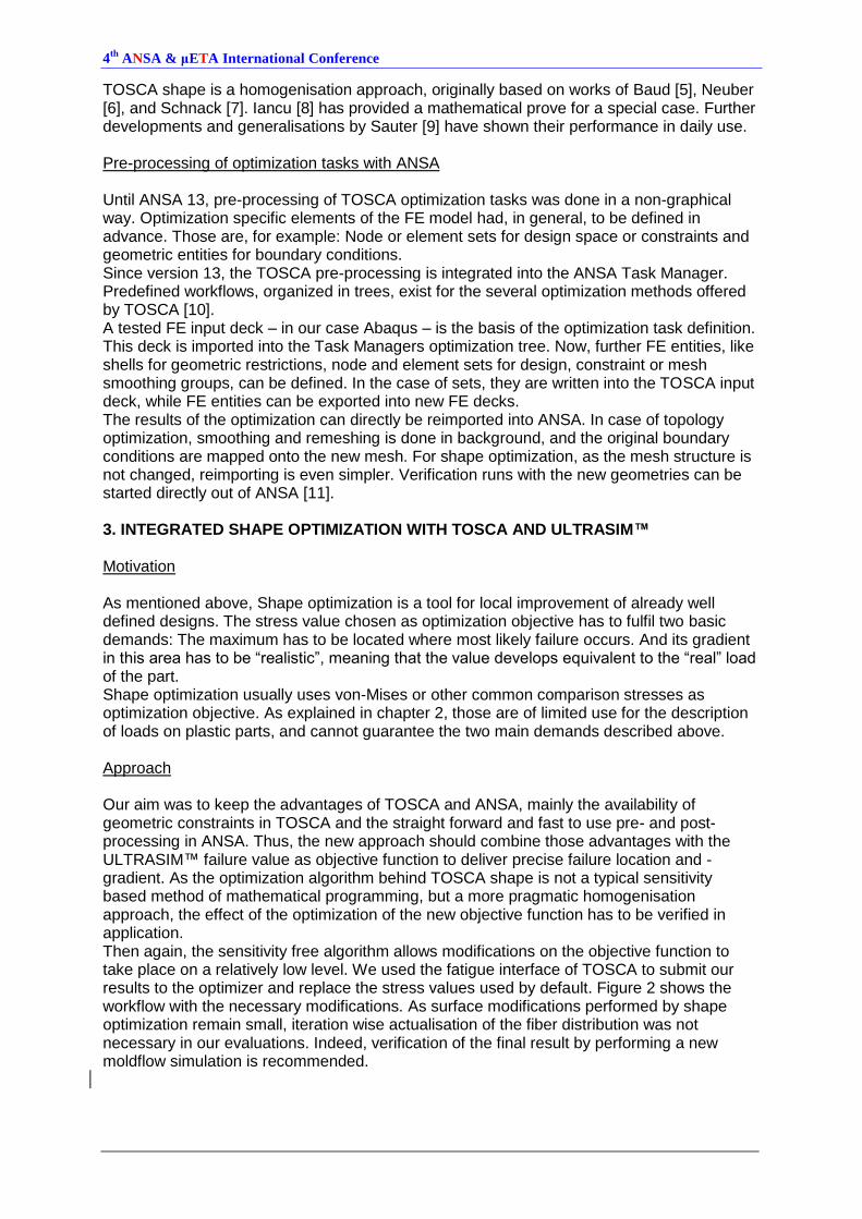
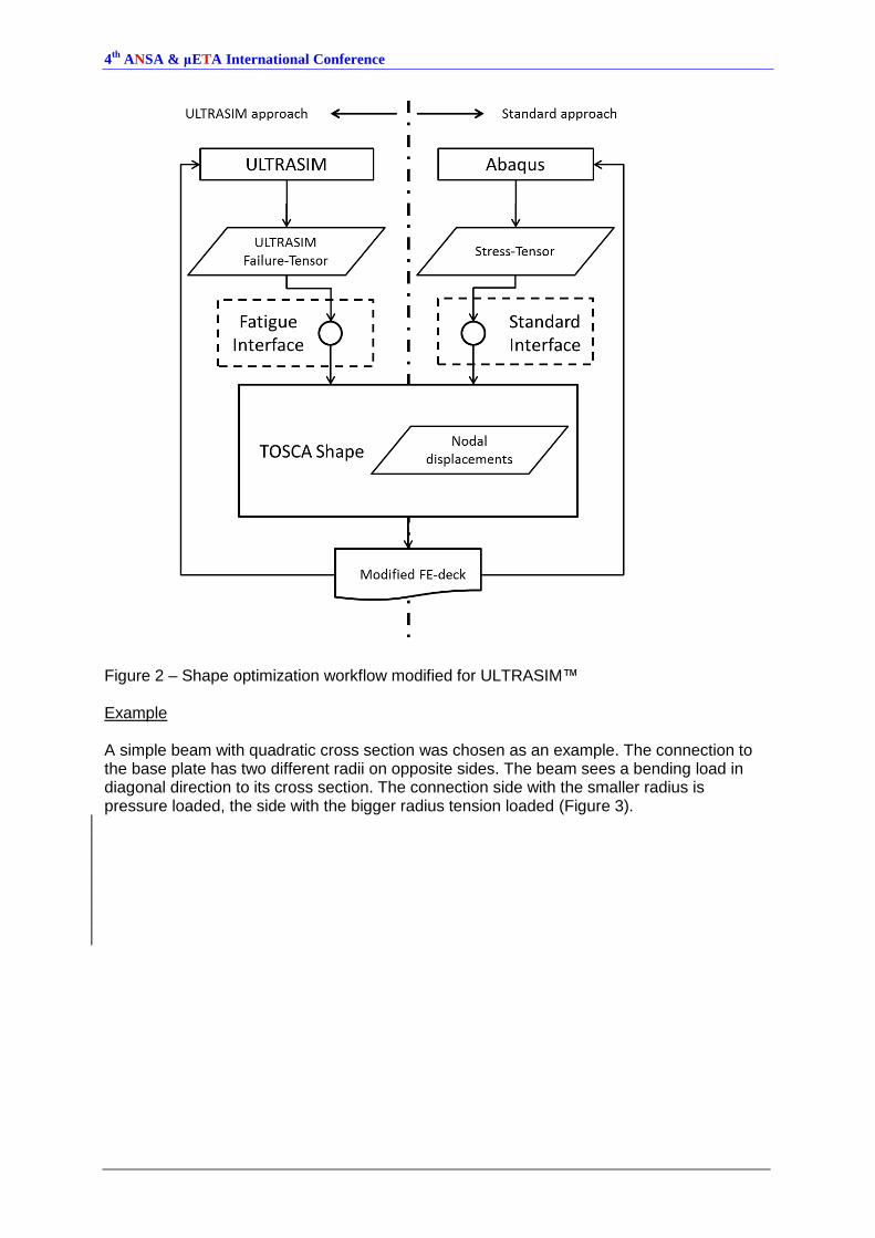
Figure 2 – Shape optimization workflow modified for ULTRASIM™ Example A simple beam with quadratic cross section was chosen as an example. The connection to the base plate has two different radii on opposite sides. The beam sees a bending load in diagonal direction to its cross section. The connection side with the smaller radius is pressure loaded, the side with the bigger radius tension loaded (Figure 3).
4th
ANSA & μETA International Conference
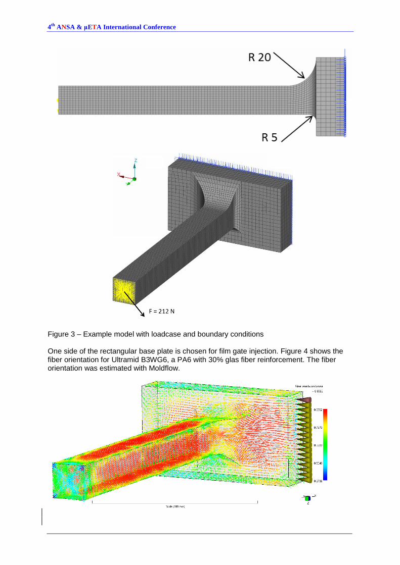
Figure 3 – Example model with loadcase and boundary conditions One side of the rectangular base plate is chosen for film gate injection. Figure 4 shows the fiber orientation for Ultramid B3WG6, a PA6 with 30% glas fiber reinforcement. The fiber orientation was estimated with Moldflow.
4th
ANSA & μETA International Conference
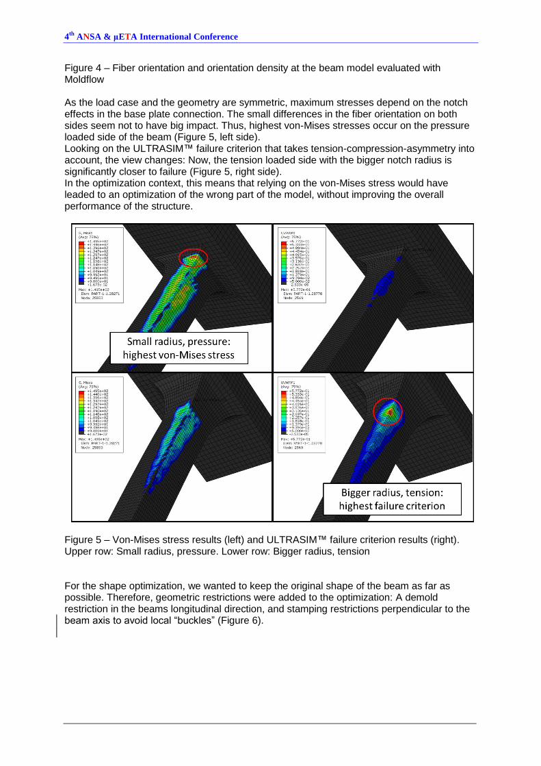
Figure 4 – Fiber orientation and orientation density at the beam model evaluated with Moldflow As the load case and the geometry are symmetric, maximum stresses depend on the notch effects in the base plate connection. The small differences in the fiber orientation on both sides seem not to have big impact. Thus, highest von-Mises stresses occur on the pressure loaded side of the beam (Figure 5, left side). Looking on the ULTRASIM™ failure criterion that takes tension-compression-asymmetry into account, the view changes: Now, the tension loaded side with the bigger notch radius is significantly closer to failure (Figure 5, right side). In the optimization context, this means that relying on the von-Mises stress would have leaded to an optimization of the wrong part of the model, without improving the overall performance of the structure.
Figure 5 – Von-Mises stress results (left) and ULTRASIM™ failure criterion results (right). Upper row: Small radius, pressure. Lower row: Bigger radius, tension For the shape optimization, we wanted to keep the original shape of the beam as far as possible. Therefore, geometric restrictions were added to the optimization: A demold restriction in the beams longitudinal direction, and stamping restrictions perpendicular to the beam axis to avoid local “buckles” (Figure 6).
4th
ANSA & μETA International Conference
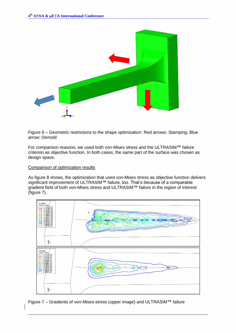
Figure 6 – Geometric restrictions to the shape optimization: Red arrows: Stamping; Blue arrow: Demold For comparison reasons, we used both von-Mises stress and the ULTRASIM™ failure criterion as objective function. In both cases, the same part of the surface was chosen as design space. Comparison of optimization results As figure 8 shows, the optimization that used von-Mises stress as objective function delivers significant improvement of ULTRASIM™ failure, too. That’s because of a comparable gradient field of both von-Mises stress and ULTRASIM™ failure in the region of interest (figure 7).
Figure 7 – Gradients of von-Mises-stress (upper image) and ULTRASIM™ failure
4th
ANSA & μETA International Conference
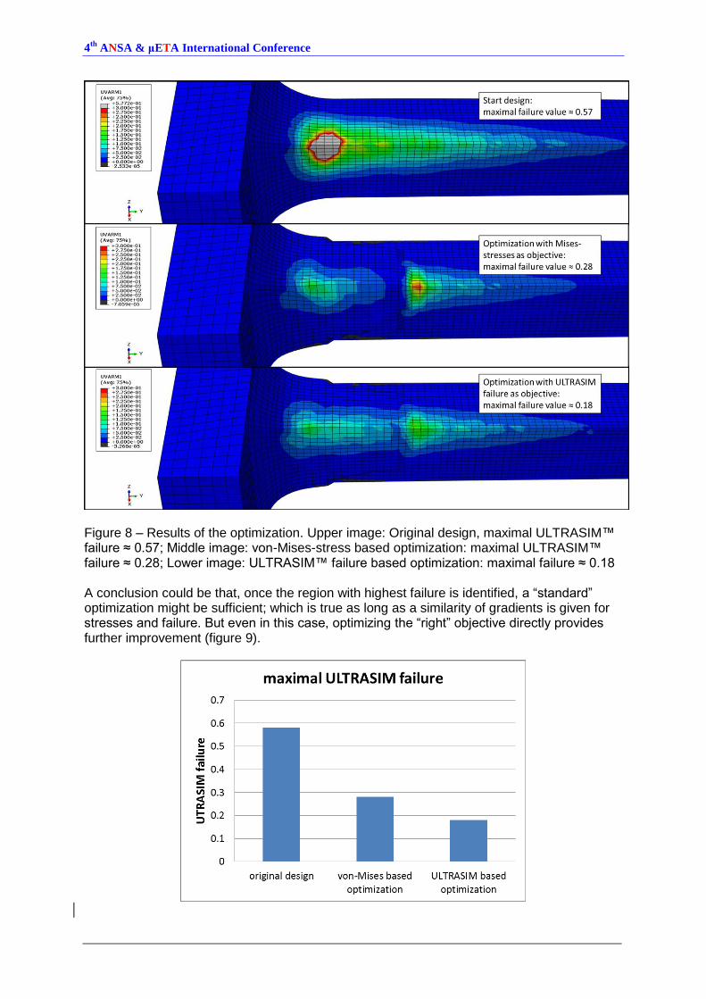
Figure 8 – Results of the optimization. Upper image: Original design, maximal ULTRASIM™ failure ≈ 0.57; Middle image: von-Mises-stress based optimization: maximal ULTRASIM™ failure ≈ 0.28; Lower image: ULTRASIM™ failure based optimization: maximal failure ≈ 0.18 A conclusion could be that, once the region with highest failure is identified, a “standard” optimization might be sufficient; which is true as long as a similarity of gradients is given for stresses and failure. But even in this case, optimizing the “right” objective directly provides further improvement (figure 9).
4th
ANSA & μETA International Conference
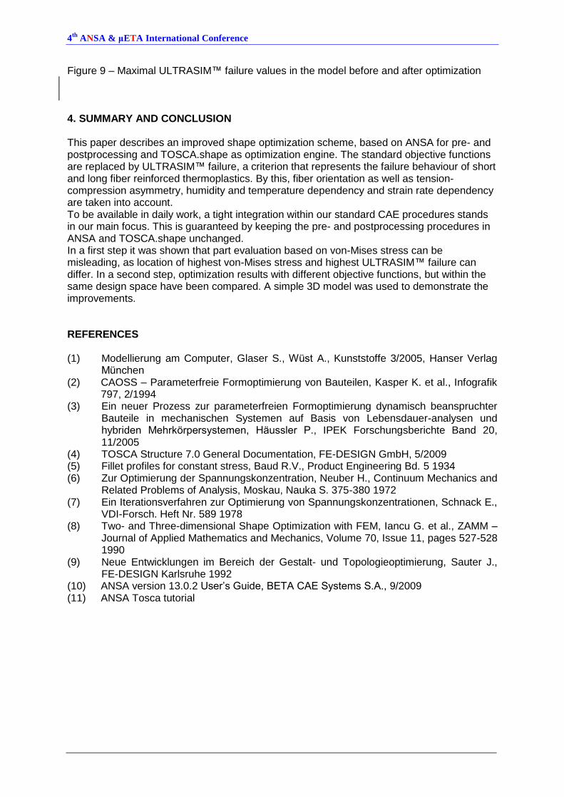
Figure 9 – Maximal ULTRASIM™ failure values in the model before and after optimization 4. SUMMARY AND CONCLUSION This paper describes an improved shape optimization scheme, based on ANSA for pre- and postprocessing and TOSCA.shape as optimization engine. The standard objective functions are replaced by ULTRASIM™ failure, a criterion that represents the failure behaviour of short and long fiber reinforced thermoplastics. By this, fiber orientation as well as tension-compression asymmetry, humidity and temperature dependency and strain rate dependency are taken into account. To be available in daily work, a tight integration within our standard CAE procedures stands in our main focus. This is guaranteed by keeping the pre- and postprocessing procedures in ANSA and TOSCA.shape unchanged. In a first step it was shown that part evaluation based on von-Mises stress can be misleading, as location of highest von-Mises stress and highest ULTRASIM™ failure can differ. In a second step, optimization results with different objective functions, but within the same design space have been compared. A simple 3D model was used to demonstrate the improvements. REFERENCES (1) Modellierung am Computer, Glaser S., Wüst A., Kunststoffe 3/2005, Hanser Verlag
München (2) CAOSS – Parameterfreie Formoptimierung von Bauteilen, Kasper K. et al., Infografik
797, 2/1994 (3) Ein neuer Prozess zur parameterfreien Formoptimierung dynamisch beanspruchter
Bauteile in mechanischen Systemen auf Basis von Lebensdauer-analysen und hybriden Mehrkörpersystemen, Häussler P., IPEK Forschungsberichte Band 20, 11/2005
(4) TOSCA Structure 7.0 General Documentation, FE-DESIGN GmbH, 5/2009 (5) Fillet profiles for constant stress, Baud R.V., Product Engineering Bd. 5 1934 (6) Zur Optimierung der Spannungskonzentration, Neuber H., Continuum Mechanics and
Related Problems of Analysis, Moskau, Nauka S. 375-380 1972 (7) Ein Iterationsverfahren zur Optimierung von Spannungskonzentrationen, Schnack E.,
VDI-Forsch. Heft Nr. 589 1978 (8) Two- and Three-dimensional Shape Optimization with FEM, Iancu G. et al., ZAMM –
Journal of Applied Mathematics and Mechanics, Volume 70, Issue 11, pages 527-528 1990
(9) Neue Entwicklungen im Bereich der Gestalt- und Topologieoptimierung, Sauter J., FE-DESIGN Karlsruhe 1992
(10) ANSA version 13.0.2 User’s Guide, BETA CAE Systems S.A., 9/2009 (11) ANSA Tosca tutorial