EXT Beam Measurements & Corrections
31
EXT Beam Measurements & Corrections Dispersion, Coupling, Beta Matching 10th ATF2 Project Meeting, June 30 2010 M. Woodley 1/31
-
Upload
cheveyo-gimenez -
Category
Documents
-
view
25 -
download
0
description
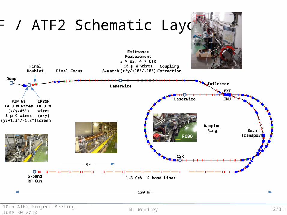
EXT Beam Measurements & Corrections. Dispersion, Coupling, Beta Matching. ATF / ATF2 Schematic Layout. Emittance Measurement 5 × WS, 4 × OTR 10 μ W wires (x/y/+10°/-10°). Final Doublet. Coupling Correction. Final Focus. β -match. Dump. Inflector. Laserwire. EXT. INJ. Laserwire. - PowerPoint PPT Presentation
Transcript of EXT Beam Measurements & Corrections
M. Woodley
EXT Beam Measurements & Corrections
Dispersion, Coupling, Beta Matching
10th ATF2 Project Meeting, June 30 2010 1/31
M. Woodley10th ATF2 Project Meeting, June 30 2010
-100 -80 -60 -40 -20 0 20-60
-50
-40
-30
-20
-10
0
10
20
30
Z (m)
X (
m)
120 m
S-bandRF Gun
1.3 GeV S-band Linac
DampingRing Beam
Transport
Inflector
CouplingCorrectionβ-matchFinal Focus
Dump
FinalDoublet
EXT
INJLaserwire
XSR
Laserwire
e-
IPBSM10 μ W wires
(x/y)screen
EmittanceMeasurement
5 × WS, 4 × OTR10 μ W wires
(x/y/+10°/-10°)
PIP WS10 μ W wires
(x/y/45°)5 μ C wires
(y/+1.3°/-1.3°)
ATF / ATF2 Schematic Layout
FOBO
2/31
M. Woodley10th ATF2 Project Meeting, June 30 2010
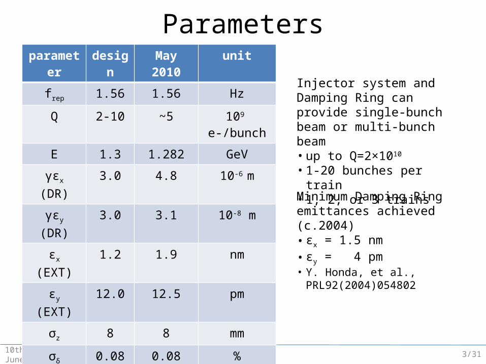
Injector system and Damping Ring can provide single-bunch beam or multi-bunch beam• up to Q=2×10¹⁰
• 1-20 bunches per train• 1, 2, or 3 trains
Minimum Damping Ring emittances achieved (c.2004)• εx = 1.5 nm• εy = 4 pm• Y. Honda, et al., PRL92(2004)054802
Parametersparameter design May 2010 unit
frep 1.56 1.56 Hz
Q 2-10 ~5 109 e-/bunch
E 1.3 1.282 GeV
γεx (DR) 3.0 4.8 10-6 m
γεy (DR) 3.0 3.1 10-8 m
εx (EXT) 1.2 1.9 nm
εy (EXT) 12.0 12.5 pm
σz 8 8 mm
σδ 0.08 0.08 %
βx* 4.0 40.0 mm
βy* 0.1 1.0 mm
η'x* 0.1394 0.1394 rad
σx* 2.2 8.7 μm
σy* 37 112 nm3/31
M. Woodley 410th ATF2 Project Meeting, June 30 2010
EMITTANCE & COUPLINGMEASUREMENT & CORRECTION
M. Woodley10th ATF2 Project Meeting, June 30 2010
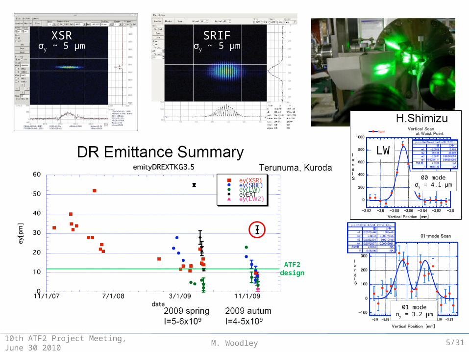
XSR SRIF
LW
00 modeσy = 4.1 μm
01 modeσy = 3.2 μm
ATF2design
σy ~ 5 μm σy ~ 5 μm
5/31
M. Woodley10th ATF2 Project Meeting, June 30 2010
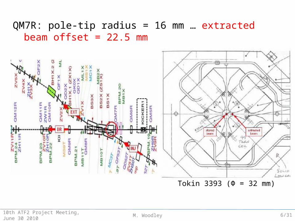
QM7R: pole-tip radius = 16 mm … extracted beam offset = 22.5 mm
Tokin 3393 (Ф = 32 mm)
6/31

M. Woodley10th ATF2 Project Meeting, June 30 2010
K1L
K0L
K2L
QM7R replaced with larger bore (Ф = 42 mm) quadrupole in January 2009
K1L = 0.3 m-1 = 0.76 nominal optics mismatch
K2L = 46.6 m-2
x-y coupling for vertically off-axis beam: factor ~ 2-3 × y for y = 1 mm (εx:εy = 100:1)
Tokin 3393 (Ф = 32 mm)
PRIAM simulation
K1L = 0.392 m-1 = 0.99 × nominal K2L = 1 m-2
Tokin 3581 (Ф = 42 mm)
Measured
7/31
M. Woodley10th ATF2 Project Meeting, June 30 2010
0 2 4 6 8 10 12 14-1.2
-1
-0.8
-0.6
-0.4
-0.2
0
0.2
Y
(m
m)
S (m)
KE
X1
QM
6R
QM
7R
BS
1X
BS
2X
BS
3X
BH
1X
QS
1X
Q
F1X
QD
2X
QF
3X
ZV
100R
X
ZV
1X
ZV
2X
ZV
3X
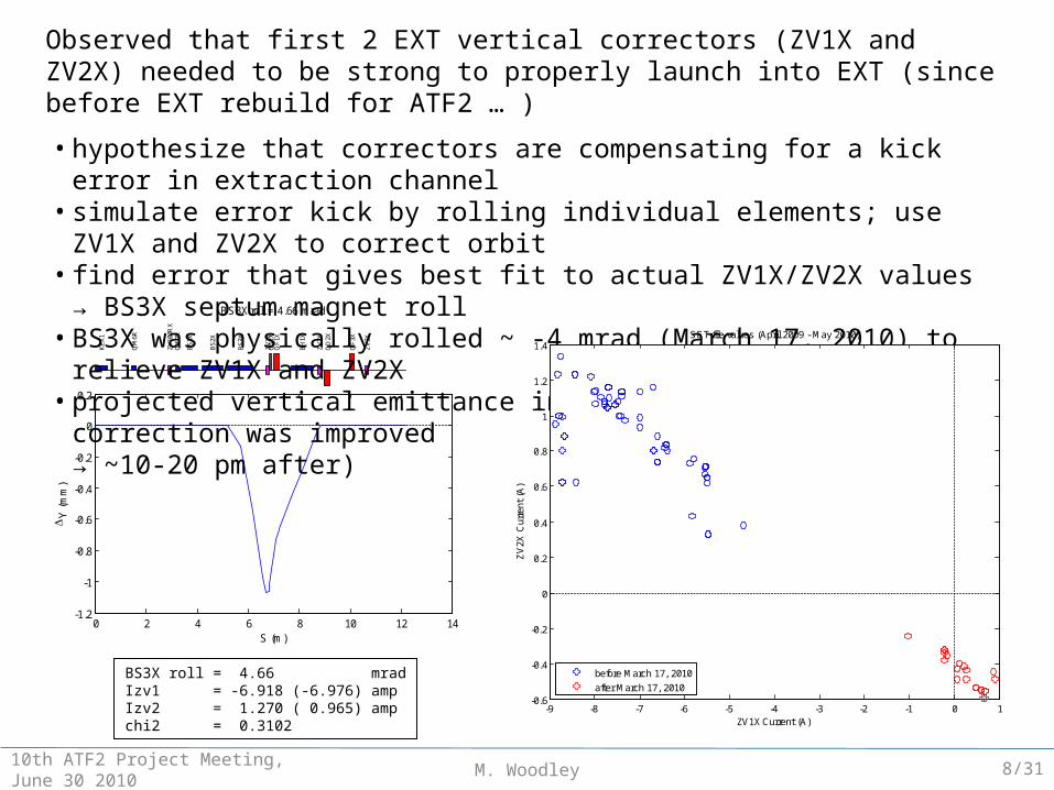
BS3X roll = 4.66 mrad
BS3X roll = 4.66 mradIzv1 = -6.918 (-6.976) ampIzv2 = 1.270 ( 0.965) ampchi2 = 0.3102
Observed that first 2 EXT vertical correctors (ZV1X and ZV2X) needed to be strong to properly launch into EXT (since before EXT rebuild for ATF2 … )
• hypothesize that correctors are compensating for a kick error in extraction channel• simulate error kick by rolling individual elements; use ZV1X and ZV2X to correct orbit• find error that gives best fit to actual ZV1X/ZV2X values → BS3X septum magnet roll• BS3X was physically rolled ~ -4 mrad (March 17, 2010) to relieve ZV1X and ZV2X• projected vertical emittance in EXT before coupling correction was improved
(~20-40 pm before → ~10-20 pm after)
-9 -8 -7 -6 -5 -4 -3 -2 -1 0 1-0.6
-0.4
-0.2
0
0.2
0.4
0.6
0.8
1
1.2
1.4SET-file values (April 2009 - May 2010)
ZV
2X C
urre
nt (
A)
ZV1X Current (A)
before March 17, 2010
after March 17, 2010
8/31
M. Woodley10th ATF2 Project Meeting, June 30 2010
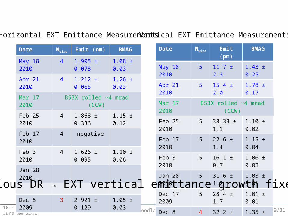
Date Nwire Emit (nm) BMAG
May 18 2010 4 1.905 ± 0.078 1.08 ± 0.03
Apr 21 2010 4 1.212 ± 0.065 1.26 ± 0.03
Mar 17 2010 BS3X rolled ~4 mrad (CCW)
Feb 25 2010 4 1.868 ± 0.336 1.15 ± 0.12
Feb 17 2010 4 negative
Feb 3 2010 4 1.626 ± 0.095 1.10 ± 0.06
Jan 28 2010
Dec 8 2009 3 2.921 ± 0.129 1.05 ± 0.03
Date Nwire Emit (pm) BMAG
May 18 2010 5 11.7 ± 2.3 1.43 ± 0.25
Apr 21 2010 5 15.4 ± 2.0 1.78 ± 0.17
Mar 17 2010 BS3X rolled ~4 mrad (CCW)
Feb 25 2010 5 38.33 ± 1.1 1.10 ± 0.02
Feb 17 2010 5 22.6 ± 1.4 1.15 ± 0.04
Feb 3 2010 5 16.1 ± 0.7 1.06 ± 0.03
Jan 28 2010 5 31.6 ± 1.2 1.03 ± 0.01
Dec 17 2009 5 28.4 ± 1.7 1.01 ± 0.01
Dec 8 2009 4 32.2 ± 1.9 1.35 ± 0.13
Horizontal EXT Emittance Measurements Vertical EXT Emittance Measurements
Anomalous DR → EXT vertical emittance growth fixed (?)
9/31
M. Woodley10th ATF2 Project Meeting, June 30 2010
25 30 35 40 45 500
2
4
6
8
10
12
14
16
18
20
Be
ta (
m)
S (m)
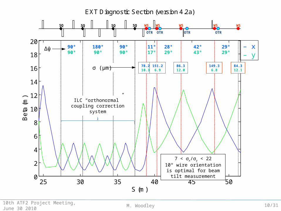
EXT Diagnostic Section (version 4.2a)
SQ SQ WS WS WS WS WS
90°90°
180°90°
90°90°
– x– y
11°17°
28°29°
42°43°
29°29°
78.210.3
151.26.9
86.312.0
149.36.8
84.312.1σ (μm)
7 < σx/σy < 2210° wire orientation is optimal
for beam tilt measurement
SQ SQ
OTR OTR OTR OTR
Δψ
ILC “orthonormal”coupling correction
system
10/31
M. Woodley10th ATF2 Project Meeting, June 30 2010
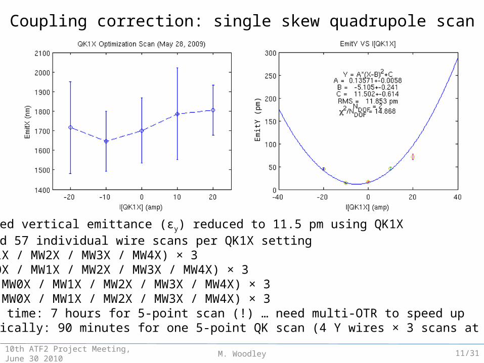
• projected vertical emittance (εy) reduced to 11.5 pm using QK1X• required 57 individual wire scans per QK1X setting
– X (MW1X / MW2X / MW3X / MW4X) × 3– Y (MW0X / MW1X / MW2X / MW3X / MW4X) × 3– +10° (MW0X / MW1X / MW2X / MW3X / MW4X) × 3– -10° (MW0X / MW1X / MW2X / MW3X / MW4X) × 3
• elapsed time: 7 hours for 5-point scan (!) … need multi-OTR to speed up• realistically: 90 minutes for one 5-point QK scan (4 Y wires × 3 scans at each point)
EmitY
(pm
)
Coupling correction: single skew quadrupole scan
11/31
M. Woodley
○ 100°* 80°
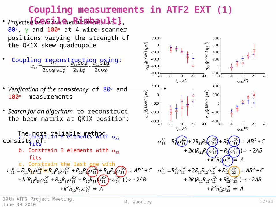
Coupling reconstruction• Projected beam size measurements at x, 80o, y and
100o at 4 wire-scanner positions varying the
strength of the QK1X skew quadrupole
• Coupling reconstruction using:
• Verification of the consistency of 80o and 100o measurements
• Search for an algorithm to reconstruct the beam matrix at QK1X position:
The more reliable method consists of:
Coupling measurements in ATF2 EXT (1) [Cecile Rimbault]
cos2
sin
sin2
cos
sincos23311
2
13
a. Constrain 6 elements with s33 fitsb. Constrain 3 elements with s13 fitsc. Constrain the last one with s11 fits
ARk
ABRRRk
CABRRRR
QK
QKQK
QKQKQKM
11234
2
14234133433
244
23434343333
23333
2)(2
2
ARk
ABRRRk
CABRRRR
QK
QKQK
QKQKQKM
33212
2
23212131211
222
21212121111
21111
2)(2
2
ARRk
ABRRRRRRk
CABRRRRRRRR
QK
QKQKQKQK
QKQKQKQKM
1334122
34123412333312113411
224341223123314341113331113
2))((
10th ATF2 Project Meeting, June 30 2010 12/31
M. Woodley
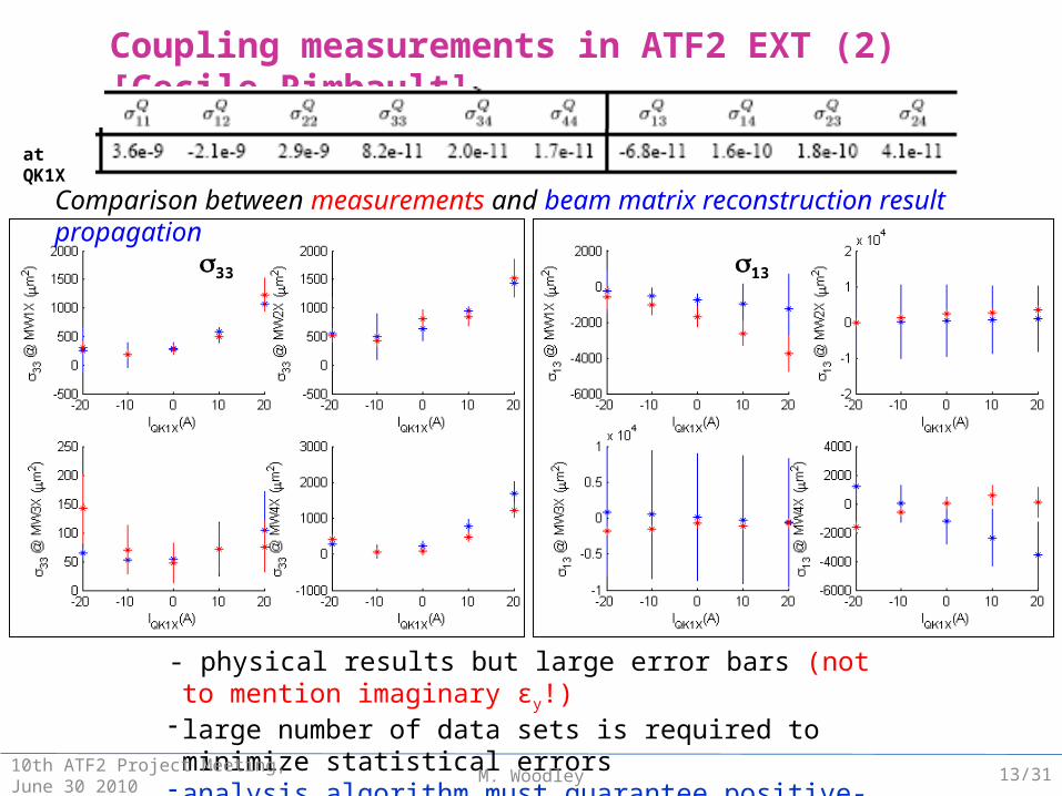
Coupling measurements in ATF2 EXT (2) [Cecile Rimbault]
Comparison between measurements and beam matrix reconstruction result propagation
s33 s13
at QK1X
- physical results but large error bars (not to mention imaginary εy!) - large number of data sets is required to minimize statistical errors- analysis algorithm must guarantee positive-definite beam matrix
10th ATF2 Project Meeting, June 30 2010 13/31
M. Woodley10th ATF2 Project Meeting, June 30 2010
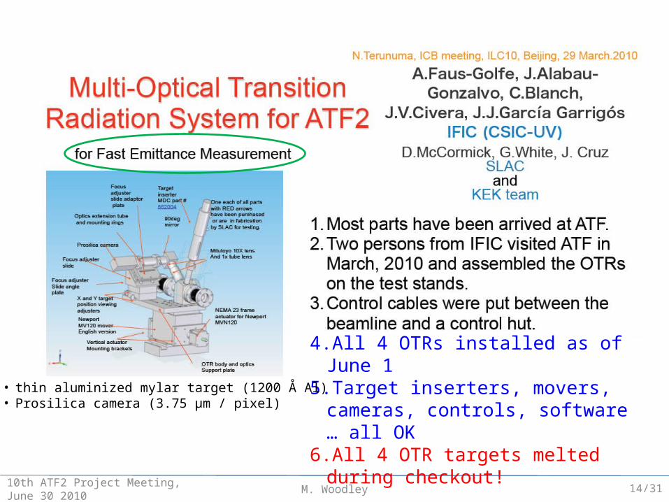
4. All 4 OTRs installed as of June 15. Target inserters, movers, cameras,
controls, software … all OK6. All 4 OTR targets melted during checkout!
• thin aluminized mylar target (1200 Å Al)• Prosilica camera (3.75 μm / pixel)
14/31
M. Woodley10th ATF2 Project Meeting, June 30 2010
pixe
lspi
xels
pixels
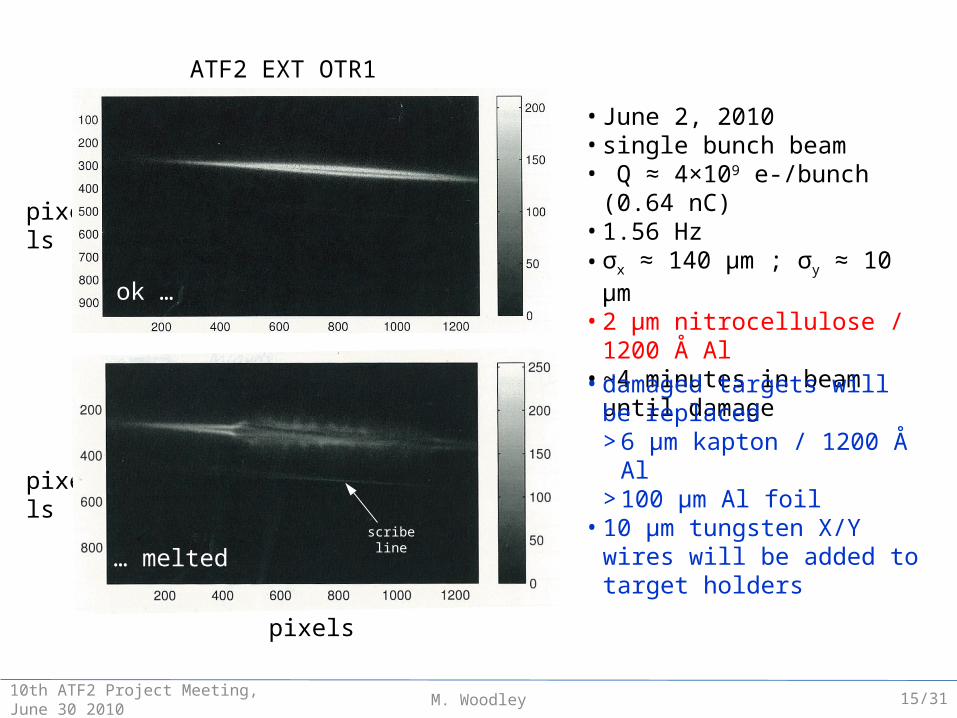
ATF2 EXT OTR1
ok …
… melted
• June 2, 2010• single bunch beam• Q ≈ 4×10⁹ e-/bunch (0.64 nC)• 1.56 Hz• σx ≈ 140 μm ; σy ≈ 10 μm• 2 μm nitrocellulose / 1200 Å Al• ~4 minutes in beam until damage
• damaged targets will be replaced> 6 μm kapton / 1200 Å Al> 100 μm Al foil
• 10 μm tungsten X/Y wires will be added to target holders
scribeline
15/31
M. Woodley 1610th ATF2 Project Meeting, June 30 2010
DISPERSIONMEASUREMENT & CORRECTION
M. Woodley10th ATF2 Project Meeting, June 30 2010
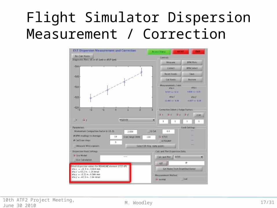
Flight Simulator DispersionMeasurement / Correction
17/31
M. Woodley10th ATF2 Project Meeting, June 30 2010
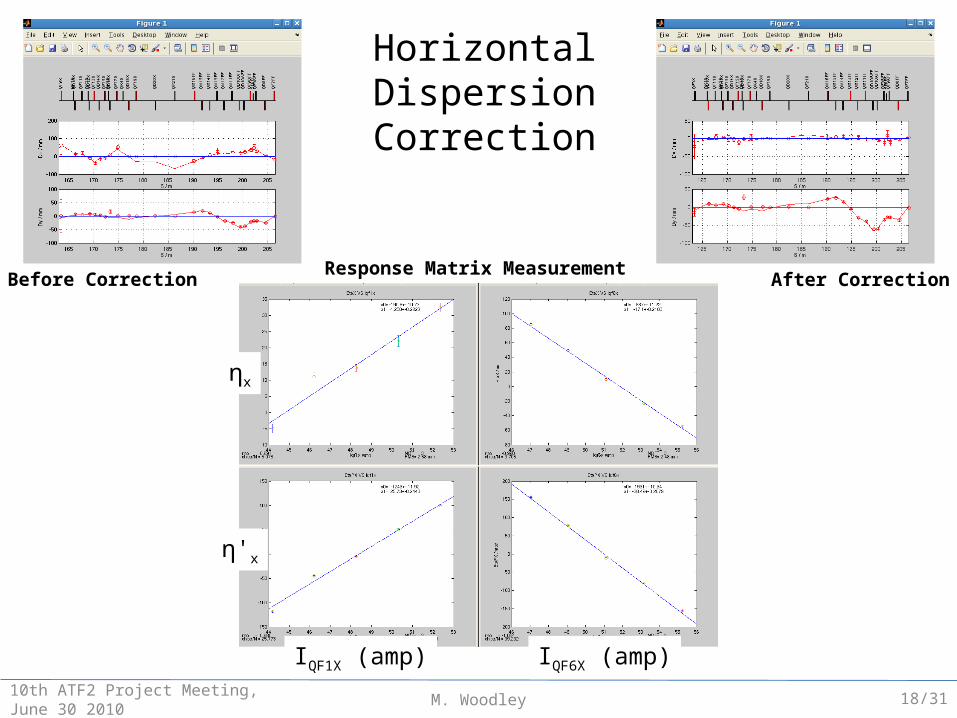
Before Correction After Correction
ηx
η'x
IQF1X (amp) IQF6X (amp)
Response Matrix Measurement
HorizontalDispersionCorrection
18/31

M. Woodley10th ATF2 Project Meeting, June 30 2010
0
10
20
1/2
XY
-0.75-0.5
-0.250
0.250.5
0.75
0 5 10 15 20-1
0
1
S (m)
KE
X1
BS
1X
BS
2X
BS
3X
BH
1X
BH
2X
BH
3X
KE
X2
QM
6R
QM
7R
QF
1X
QD
2X
QF
3X
QF
4X
QD
5X
QF
6X
QF
7X
QD
8X
QS1X QS2X
“Sum-Knob”: IQS1X = IQS2X
Simulated ηy* (right) and η'y* (right),back-propagated from IP
Vertical Dispersion Correction(FD-phase)
Δ Sum-Knob = -0.15 A
IP-phase FD-phase
19/31
M. Woodley10th ATF2 Project Meeting, June 30 2010
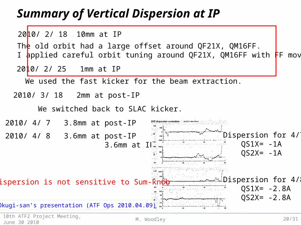
2010/ 2/ 18 10mm at IP
The old orbit had a large offset around QF21X, QM16FF.I applied careful orbit tuning around QF21X, QM16FF with FF mover.
2010/ 2/ 25 1mm at IP
2010/ 3/ 18 2mm at post-IP
We used the fast kicker for the beam extraction.
We switched back to SLAC kicker.
2010/ 4/ 7 3.8mm at post-IP
2010/ 4/ 8 3.6mm at post-IP 3.6mm at IP
Dispersion for 4/7 QS1X= -1A QS2X= -1A
Dispersion for 4/8 QS1X= -2.8A QS2X= -2.8A
Summary of Vertical Dispersion at IP
IP dispersion is not sensitive to Sum-knob
From Okugi-san’s presentation (ATF Ops 2010.04.09)
20/31

M. Woodley 2110th ATF2 Project Meeting, June 30 2010
BETA MATCHING

M. Woodley10th ATF2 Project Meeting, June 30 2010
*
*
* *
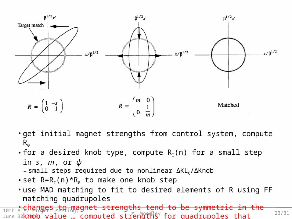
100 01 cos sin11
00 1 sin cos00
ms
m
RI =
waist shift magnification phase shift (α* 0)
alphaknob
betaknob
phaseknob
“Irwin Knobs” for β-matching : R = RI × R0
“Irwin Knobs”
40 45 50 55 60 65 70 75 80 85-2.5
-2.25
-2
-1.75
-1.5
-1.25
-1
-0.75
-0.5
-0.25
0
(ra
d/2
)
S (m)
B5
FF
B2
FF
B1
FF
QD
18
X
QF
19
X
QD
20
X
QF
21
X
QM
16
FF
QM
15
FF
QM
14
FF
QM
13
FF
QM
12
FF
QM
11
FF
QD
10
BF
F
QD
10
AF
F
QF
9B
FF
QF
9A
FF
QD
8F
F
QF
7F
F
QD
6F
F
QF
5B
FF
QF
5A
FF
QD
4B
FF
QD
4A
FF
QF
3F
F
QD
2B
FF
QD
2A
FF
QF
1F
F
QD
0F
F
SF
6F
F
SF
5F
F
SD
4F
F
SF
1F
F
SD
0F
F
ATF2 pulse-to-pulse feedback devices (v3.7)
XY
R0
Final Focus
22/31
M. Woodley10th ATF2 Project Meeting, June 30 2010
• get initial magnet strengths from control system, compute R0
• for a desired knob type, compute RI(n) for a small step in s, m, or ψ– small steps required due to nonlinear ΔKLQ/ΔKnob
• set R=RI(n)*R0 to make one knob step• use MAD matching to fit to desired elements of R using FF matching quadrupoles• changes to magnet strengths tend to be symmetric in the knob value … computed
strengths for quadrupoles that start at zero tend to go bipolar• tried waist shift and magnification knobs during tuning week … seem OK
23/31
M. Woodley10th ATF2 Project Meeting, June 30 2010
-4 -2 0 2 419.6
19.8
2020.2
20.420.6
20.8
QM
16
FF
(a
mp
s)
-4 -2 0 2 427
27.2
27.4
QM
15
FF
(a
mp
s)
-4 -2 0 2 455
56
57
58
QM
14
FF
(a
mp
s)
-4 -2 0 2 436
36.5
37
37.5
QM
13
FF
(a
mp
s)
-4 -2 0 2 4
14
15
16
17
QM
12
FF
(a
mp
s)
Wy (mm)
-4 -2 0 2 4
-0.2
0
0.2
QM
11
FF
(a
mp
s)
QM*FF Currents (amps)IP Twiss Parameters
-4 -2 0 2 4
3.8
4
4.2
4.4
x (cm
)
-4 -2 0 2 4-1
-0.5
0
0.5
1
x
-4 -2 0 2 4-1
-0.5
0
0.5
1
x (
de
g)
-4 -2 0 2 4
5
10
15
20
25
y (m
m)
-4 -2 0 2 4
-4
-2
0
2
4
y
Wy (mm)
-4 -2 0 2 4
-10
-5
0
5
10
y (
de
g)
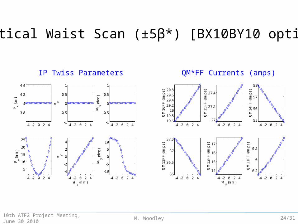
Vertical Waist Scan (±5β*) [BX10BY10 optics]
24/31

M. Woodley10th ATF2 Project Meeting, June 30 2010
Vertical Magnification Scan (0.5-2) [BX10BY10 optics]
QM*FF Currents (amps)IP Twiss Parameters
0.5 1 1.5 2
3.8
4
4.2
4.4
x (cm
)
0.5 1 1.5 2-1
-0.5
0
0.5
1 x
0.5 1 1.5 2-1
-0.5
0
0.5
1
x (
de
g)
0.5 1 1.5 20.5
1
1.5
y (m
m)
0.5 1 1.5 2-1
-0.5
0
0.5
1
y
My
0.5 1 1.5 2-1
-0.5
0
0.5
1
y (
de
g)
0.5 1 1.5 2
18
20
22
24
QM
16
FF
(a
mp
s)
0.5 1 1.5 2
26
27
28
29
QM
15
FF
(a
mp
s)
0.5 1 1.5 2
55
60
65
QM
14
FF
(a
mp
s)
0.5 1 1.5 2
34
36
38
QM
13
FF
(a
mp
s)
0.5 1 1.5 2
10
15
20
QM
12
FF
(a
mp
s)
My
0.5 1 1.5 2-1
0
1
QM
11
FF
(a
mp
s)
0
*
y y y*M My
y
m
25/31
M. Woodley10th ATF2 Project Meeting, June 30 2010
QM*FF Currents (amps)IP Twiss Parameters
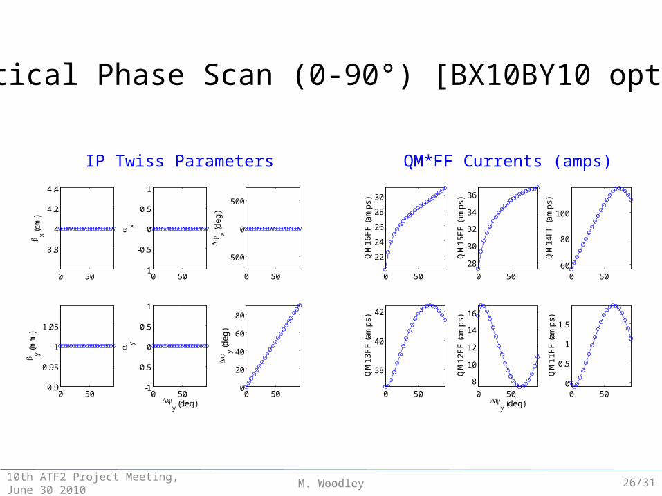
Vertical Phase Scan (0-90°) [BX10BY10 optics]
0 50
3.8
4
4.2
4.4
x (cm
)
0 50-1
-0.5
0
0.5
1
x
0 50
-500
0
500
x (
de
g)
0 500.9
0.95
1
1.05
y (m
m)
0 50-1
-0.5
0
0.5
1
y
y (deg)
0 500
20
40
60
80
y (
de
g)
0 50
22
24
26
28
30
QM
16
FF
(a
mp
s)
0 50
28
30
32
34
36
QM
15
FF
(a
mp
s)
0 5060
80
100
QM
14
FF
(a
mp
s)
0 50
38
40
42
QM
13
FF
(a
mp
s)
0 50
8
10
12
14
16
QM
12
FF
(a
mp
s)
y (deg)
0 500
0.5
1
1.5
QM
11
FF
(a
mp
s)
26/31
M. Woodley10th ATF2 Project Meeting, June 30 2010
30 40 50 60 70 800
5
10
15
20
25
30
35
40
B5F
F
B2F
F
B1F
F
QF
9X
QD
10X
QF
11X
QD
12X
QF
13X
QD
14X
QF
15X
QD
16X
QF
17X
QD
18X
QF
19X
QD
20X
QF
21X
QM
16F
F
QM
15F
F
QM
14F
F
QM
13F
F
QM
12F
F
QM
11F
F
QD
10B
FF
Q
D10
AF
F
QF
9BF
F
Q
F9A
FF
QD
8FF
QF
7FF
QD
6FF
QF
5BF
F
Q
F5A
FF
QD
4BF
F
Q
D4A
FF
QF
3FF
QD
2BF
F
QD
2AF
F
QF
1FF
QD
0FF
SF
6FF
SF
5FF
SD
4FF
SF
1FF
SD
0FF
R0
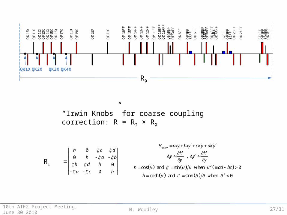
QK1X QK2X QK3X QK4X
RI =
0
0
0
0
h c d
h a b
b d h
a c h
2
2
,
cos and sin when 0
cosh and sinh when 0
skewH axy bxy cx y dx y
H Hy y
y y
h ad bc
h
“Irwin Knobs” for coarse coupling correction: R = RI × R0
27/31
M. Woodley10th ATF2 Project Meeting, June 30 2010
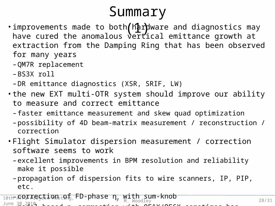
Summary (1)• improvements made to both hardware and diagnostics may have cured the
anomalous vertical emittance growth at extraction from the Damping Ring that has been observed for many years– QM7R replacement– BS3X roll– DR emittance diagnostics (XSR, SRIF, LW)
• the new EXT multi-OTR system should improve our ability to measure and correct emittance– faster emittance measurement and skew quad optimization– possibility of 4D beam-matrix measurement / reconstruction / correction
• Flight Simulator dispersion measurement / correction software seems to work– excellent improvements in BPM resolution and reliability make it possible– propagation of dispersion fits to wire scanners, IP, PIP, etc.– correction of FD-phase ηy with sum-knob
– model-based ηx correction with QF1X/QF6X sometimes has trouble, but “manual” correction works
– jitter-based (SVD) dispersion measurement / monitoring still a possibility
28/31
M. Woodley10th ATF2 Project Meeting, June 30 2010
Summary (2)• Flight Simulator “Irwin” knobs provide possibility of orthogonal “manual” β-
matching– QM*FF only … FF / FD magnets can remain at design strengths– orthogonal waist and β control– orthogonal phase control … intriguing possibilities (vertical dispersion, feedback, … )– control of IP x-y and x'-y coupling may also be possible
29/31
M. Woodley10th ATF2 Project Meeting, June 30 2010
Ongoing Work (1)• need to archive future EXT multi-wire and multi-OTR emittance measurements
– raw beam sizes, raw dispersion data, wire-to-wire and IEX to MW0X R-matrices– analysis results (with errors)
• coupling measurement / 4D beam reconstruction– acquire full data set (X/Y/U/+10/-10) plus raw data files for all EXT wires– cross-check raw data normalization and who’s who … is everything OK now?– acquire OTR beam images for all EXT OTRs and extract lengths of semi-major and semi-
minor axes and ellipse tilt angles– try 4D reconstruction … Ilya Agapov’s “Cholesky decomposition” method?
• consistency checks for emittance and Twiss– forward propagate from EXT– backward propagate from IP
• Flight Simulator computer control of Damping Ring RF frequency ramp
30/31
M. Woodley10th ATF2 Project Meeting, June 30 2010
Ongoing Work (2)
• find a better “coarse” IP-phase ηy knob– closed bump in FF matching quadrupole region?– generate in Damping Ring?– is there a way to use the “Kubo bump” to control IP-phase vertical dispersion?
• Flight Simulator “Irwin” knob development– GUI– FF optics with all QM*FF ON at reasonable currents– coupling knobs
• revisit SLAC epoxy kicker multipoles (if we don’t switch to fast stripline extraction permanently)– are observed EXT BMAG values consistent?– why are vertical bumps at KEX1 closed? are the kickers identical?– is there a way to use the “Kubo bump” to control IP-phase vertical dispersion?
• and on and on …
31/31