Exe Plk parafoudres 8 pages uk - 4.imimg.com lines Direct impact on ... Installation of primary SPD...
8
Surge Protection Devices S URGE P ROTECTION D EVICES Surge Protection Devices Low voltage Networks
Transcript of Exe Plk parafoudres 8 pages uk - 4.imimg.com lines Direct impact on ... Installation of primary SPD...
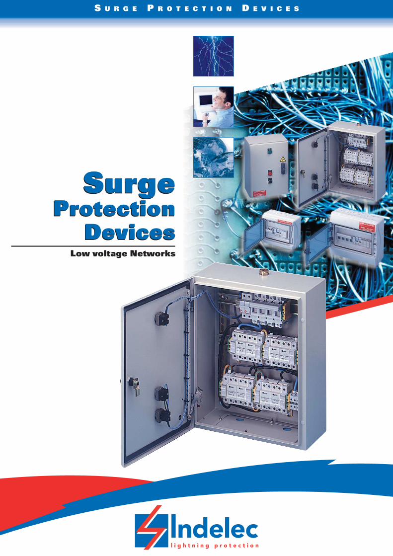
SurgeProtection
Devices
S U R G E P R O T E C T I O N D E V I C E S
SurgeProtection
DevicesLow voltage Networks
S U R G E P R O T E C T I O N D E V I C E S
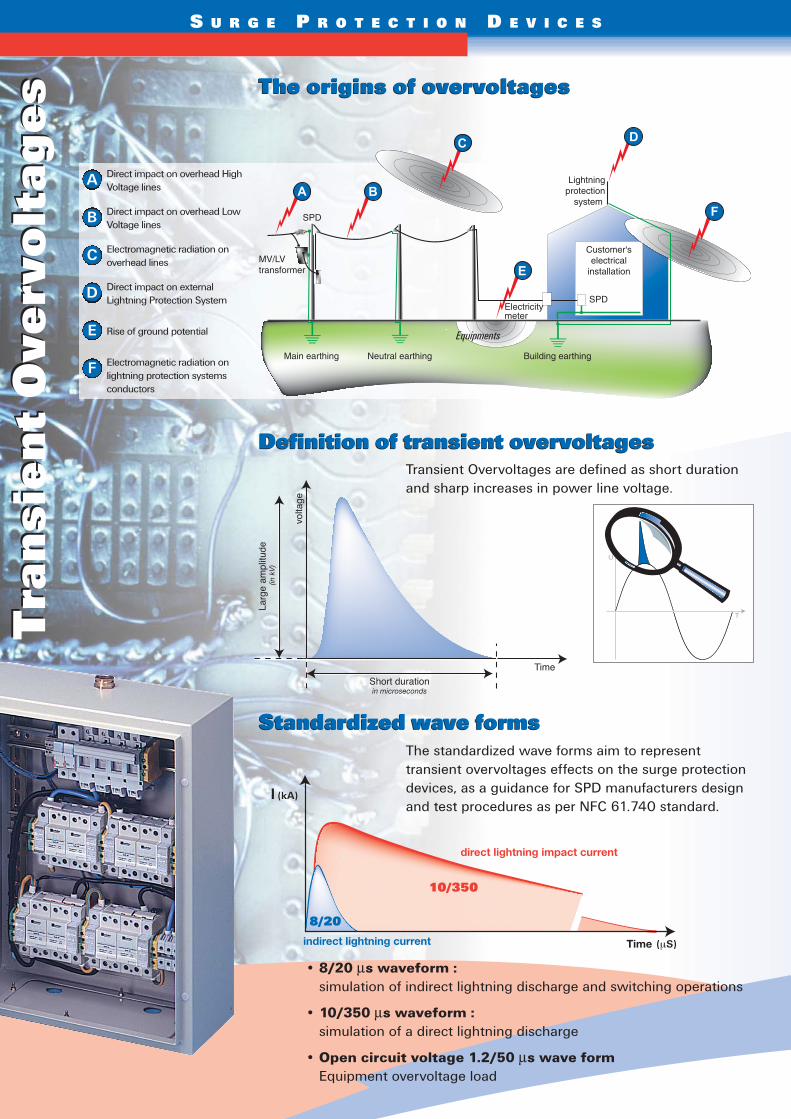
The origins of overvoltagesThe origins of overvoltages
Definition of transient overvoltagesDefinition of transient overvoltages
• 8/20 μs waveform :simulation of indirect lightning discharge and switching operations
• 10/350 μs waveform :simulation of a direct lightning discharge
• Open circuit voltage 1.2/50 μs wave formEquipment overvoltage load
Equipments
Larg
e am
plitu
de (i
n kV
)
Short durationin microseconds
volta
ge
Time
Standardized wave formsStandardized wave forms
direct lightning impact current
Timeindirect lightning current
Tra
nsi
en
t O
verv
olt
age
sT
ran
sie
nt
Ove
rvo
ltag
es
T
U
Transient Overvoltages are defined as short durationand sharp increases in power line voltage.
The standardized wave forms aim to representtransient overvoltages effects on the surge protectiondevices, as a guidance for SPD manufacturers designand test procedures as per NFC 61.740 standard.
A
B
C
D
E
F
Direct impact on overhead HighVoltage lines
Direct impact on overhead LowVoltage lines
Electromagnetic radiation onoverhead lines
Direct impact on externalLightning Protection System
Rise of ground potential
Electromagnetic radiation onlightning protection systemsconductors
S U R G E P R O T E C T I O N D E V I C E S
Transient currents consequences for the equipmentTransient currents consequences for the equipment
World lightning density map (Ng)World lightning density map (Ng)
Choosing Surge Protection DevicesChoosing Surge Protection Devices
• Destruction (partial or complete)
• Interference with normal operation
• Premature ageing
• Latent degradation
Case N°1 : Building equipped with anexternal lightning protection system
Case N°2 : Building not equipped with anexternal lightning protection system
Worsening factors> increasing number of sensitive equipment
> electronic equipment increasing sensibility to transient currents> uninterruptible service requirement
> costs of service interruption> standard requirements for SPD installation
Type1 surge arrester is mandatory.
Type1 SPD technical characteristics requirements:
- 10/350 μs waveform test- Iimp > 12.5 kA
- Up < 2.5kV UTE
C15
-44
3 t
able
Building and power supply specifications
Lightning density (Ng)Keraunic Level (Nk)
Ng ≤ 2,5 Ng > 2,5Nk ≤ 25 Nk > 25
Building equipped with an external lightning Mandatory Mandatory
protection system
Building connected to completely or partially Recommended (2) Recommendedoverhead low voltage power line
Building connected to underground Recommended (2) Recommendedlow voltage power line
Personal safety may be endangered Based on risk Mandatoryby service interruption (1) assessment survey
(1) For example, buildings equipped with medical equipment, fire safety equipment, alarms…
(2) SPD may be required depending on the type of equipment (sensitivity, costs…) or the consequences of serviceinterruption (downtime costs, ….).• If the lightning density Ng > 2.5 - Type1 or Type2 SPD
are required at the main switchboard.• If lightning density Ng < 2.5 - installation of Type1 or
Type2 SPD are recommended.
S U R G E P R O T E C T I O N D E V I C E S
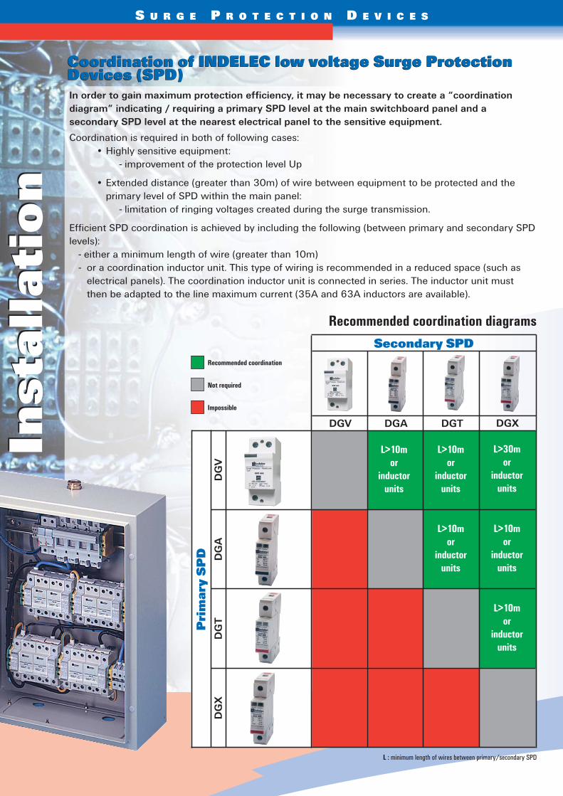
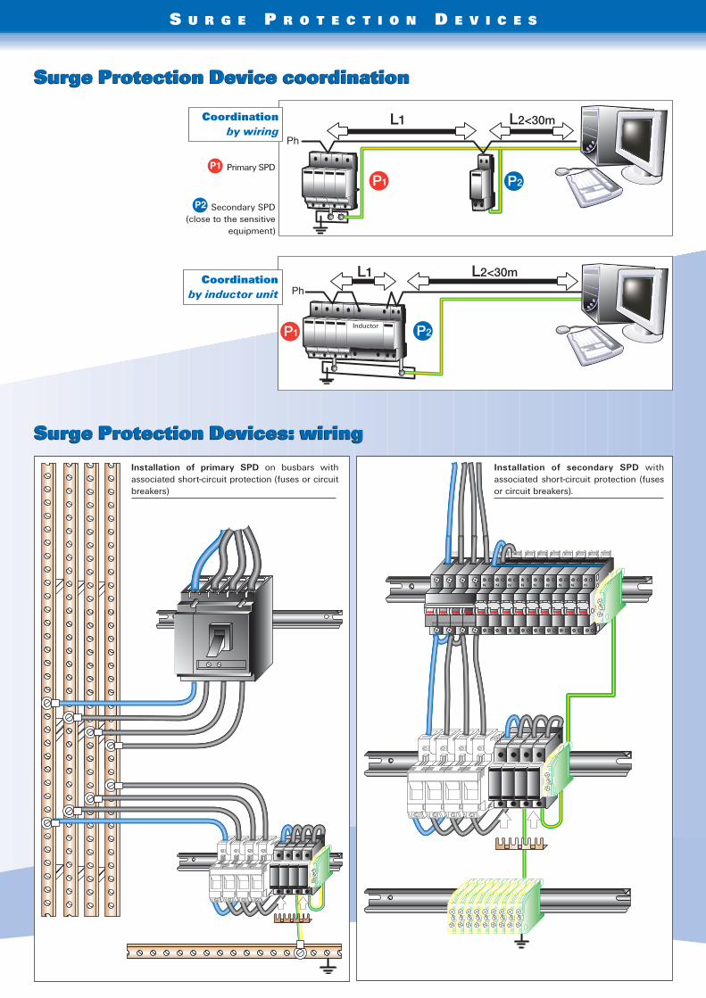
Coordination of INDELEC low voltage Surge ProtectionDevices (SPD)Coordination of INDELEC low voltage Surge ProtectionDevices (SPD)
Inst
alla
tio
nIn
stal
lati
on
In order to gain maximum protection efficiency, it may be necessary to create a “coordinationdiagram” indicating / requiring a primary SPD level at the main switchboard panel and asecondary SPD level at the nearest electrical panel to the sensitive equipment.
Coordination is required in both of following cases:• Highly sensitive equipment:
- improvement of the protection level Up
• Extended distance (greater than 30m) of wire between equipment to be protected and theprimary level of SPD within the main panel:
- limitation of ringing voltages created during the surge transmission.
Efficient SPD coordination is achieved by including the following (between primary and secondary SPDlevels):
- either a minimum length of wire (greater than 10m)- or a coordination inductor unit. This type of wiring is recommended in a reduced space (such as
electrical panels). The coordination inductor unit is connected in series. The inductor unit mustthen be adapted to the line maximum current (35A and 63A inductors are available).
Recommended coordination
Not required
Impossible
L>10mor
inductorunits
L>10mor
inductorunits
L>10mor
inductorunits
L>10mor
inductorunits
L>10mor
inductorunits
L>30mor
inductorunits
Secondary SPD
Pri
mar
y S
PD
Recommended coordination diagrams
DGV DGA DGT DGX
DG
VD
GA
DG
TD
GX
L : minimum length of wires between primary/secondary SPD
S U R G E P R O T E C T I O N D E V I C E S
Installation of primary SPD on busbars withassociated short-circuit protection (fuses or circuitbreakers)
Installation of secondary SPD withassociated short-circuit protection (fusesor circuit breakers).
Surge Protection Device coordinationSurge Protection Device coordination
Surge Protection Devices: wiringSurge Protection Devices: wiring
Primary SPD
Inductor
Secondary SPD(close to the sensitive
equipment)
Coordinationby wiring
Coordinationby inductor unit
P1
P2
S U R G E P R O T E C T I O N D E V I C E S
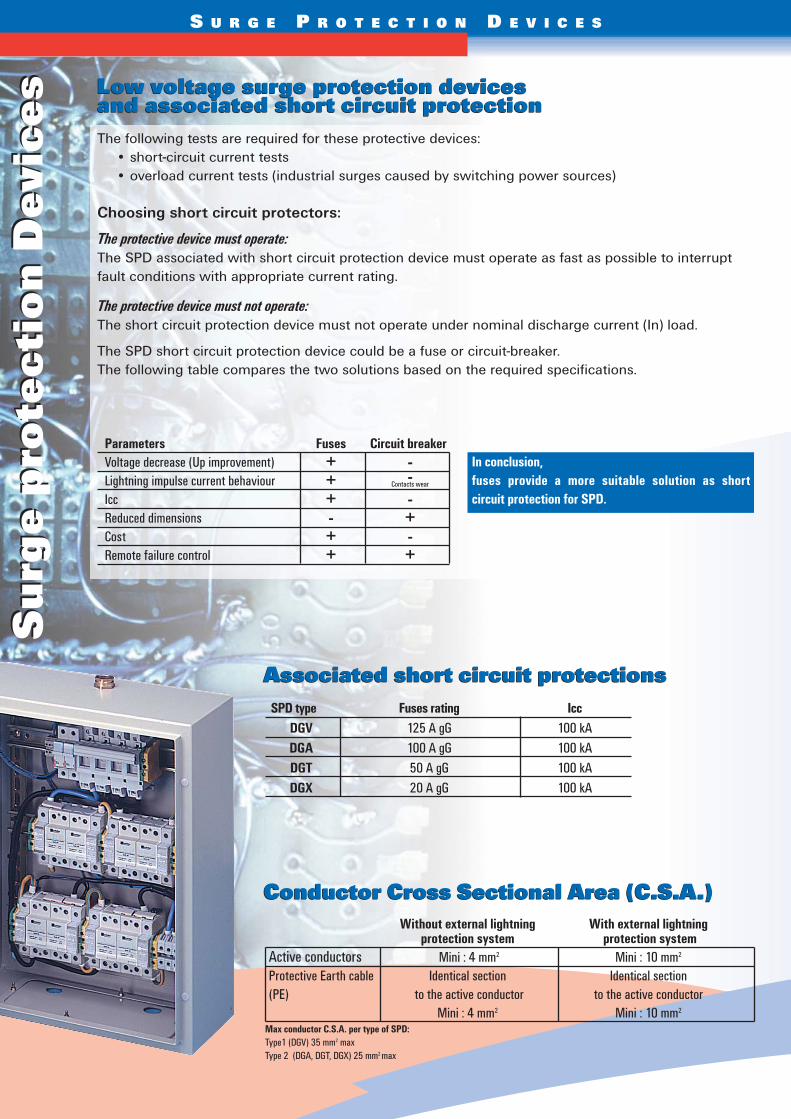
Low voltage surge protection devices and associated short circuit protectionLow voltage surge protection devices and associated short circuit protection
Associated short circuit protectionsAssociated short circuit protections
Su
rge
pro
tec
tio
n D
evi
ce
sS
urg
e p
rote
cti
on
De
vic
es
The following tests are required for these protective devices:• short-circuit current tests• overload current tests (industrial surges caused by switching power sources)
Choosing short circuit protectors:
The protective device must operate: The SPD associated with short circuit protection device must operate as fast as possible to interruptfault conditions with appropriate current rating.
The protective device must not operate:The short circuit protection device must not operate under nominal discharge current (In) load.
The SPD short circuit protection device could be a fuse or circuit-breaker.The following table compares the two solutions based on the required specifications.
Parameters Fuses Circuit breakerVoltage decrease (Up improvement) + -Lightning impulse current behaviour + -Icc + -Reduced dimensions - +Cost + -Remote failure control + +
SPD type Fuses rating IccDGV 125 A gG 100 kADGA 100 A gG 100 kADGT 50 A gG 100 kADGX 20 A gG 100 kA
Conductor Cross Sectional Area (C.S.A.)Conductor Cross Sectional Area (C.S.A.)Without external lightning With external lightning
protection system protection systemActive conductors Mini : 4 mm2 Mini : 10 mm2
Protective Earth cable Identical section Identical section (PE) to the active conductor to the active conductor
Mini : 4 mm2 Mini : 10 mm2
Contacts wear
In conclusion,fuses provide a more suitable solution as shortcircuit protection for SPD.
Max conductor C.S.A. per type of SPD:Type1 (DGV) 35 mm2 maxType 2 (DGA, DGT, DGX) 25 mm2 max
S U R G E P R O T E C T I O N D E V I C E S
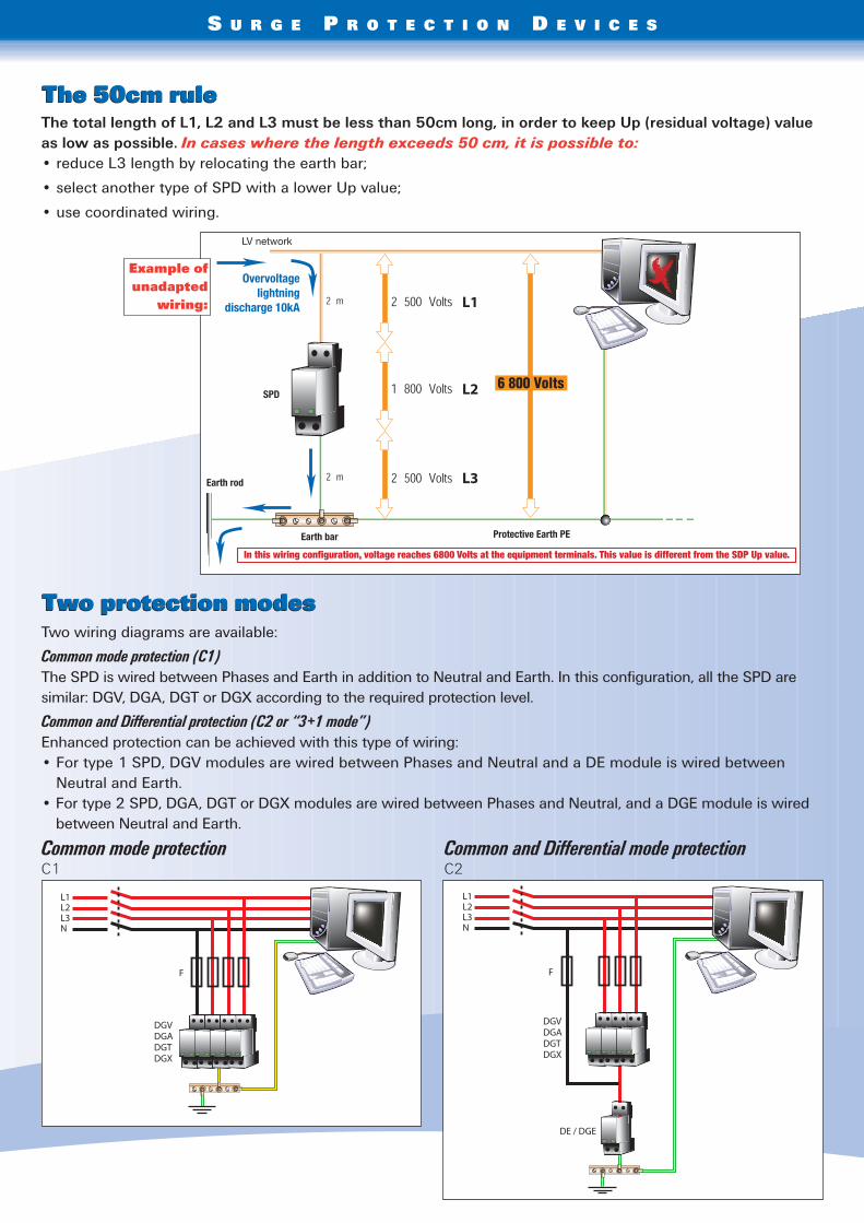
Two wiring diagrams are available:
Common mode protection (C1)The SPD is wired between Phases and Earth in addition to Neutral and Earth. In this configuration, all the SPD aresimilar: DGV, DGA, DGT or DGX according to the required protection level.
Common and Differential protection (C2 or “3+1 mode”)Enhanced protection can be achieved with this type of wiring:• For type 1 SPD, DGV modules are wired between Phases and Neutral and a DE module is wired between
Neutral and Earth.• For type 2 SPD, DGA, DGT or DGX modules are wired between Phases and Neutral, and a DGE module is wired
between Neutral and Earth.
Common mode protectionC1
Common and Differential mode protection C2
Overvoltagelightning
discharge 10kA
SPD
Earth rod
Earth bar
LV network
Protective Earth PE
In this wiring configuration, voltage reaches 6800 Volts at the equipment terminals. This value is different from the SDP Up value.
The 50cm ruleThe 50cm rule
Two protection modesTwo protection modes
The total length of L1, L2 and L3 must be less than 50cm long, in order to keep Up (residual voltage) valueas low as possible. In cases where the length exceeds 50 cm, it is possible to:• reduce L3 length by relocating the earth bar;
• select another type of SPD with a lower Up value;
• use coordinated wiring.
Example ofunadapted
wiring:
S U R G E P R O T E C T I O N D E V I C E S
61, chemin des Postes - 59500 Douai - FRANCETél : +33 (0) 327. 944. 942 - Fax : +33 (0) 327. 944. 955 - e-mail : [email protected]
Main earth bar
LV panel
Equipment
LVHV
LV panel
Main earth bar
LVHV
Equipment
Main earth bar
LVHV
Equipment
LV panel
Main earth bar
LVHV
Equipment
LV panel
Main earth bar
LVHV
Equipment
LV panel
Main earth bar
LVHV
Equipment
LV panel
Main earth bar
LVHV
Equipment
LV panel
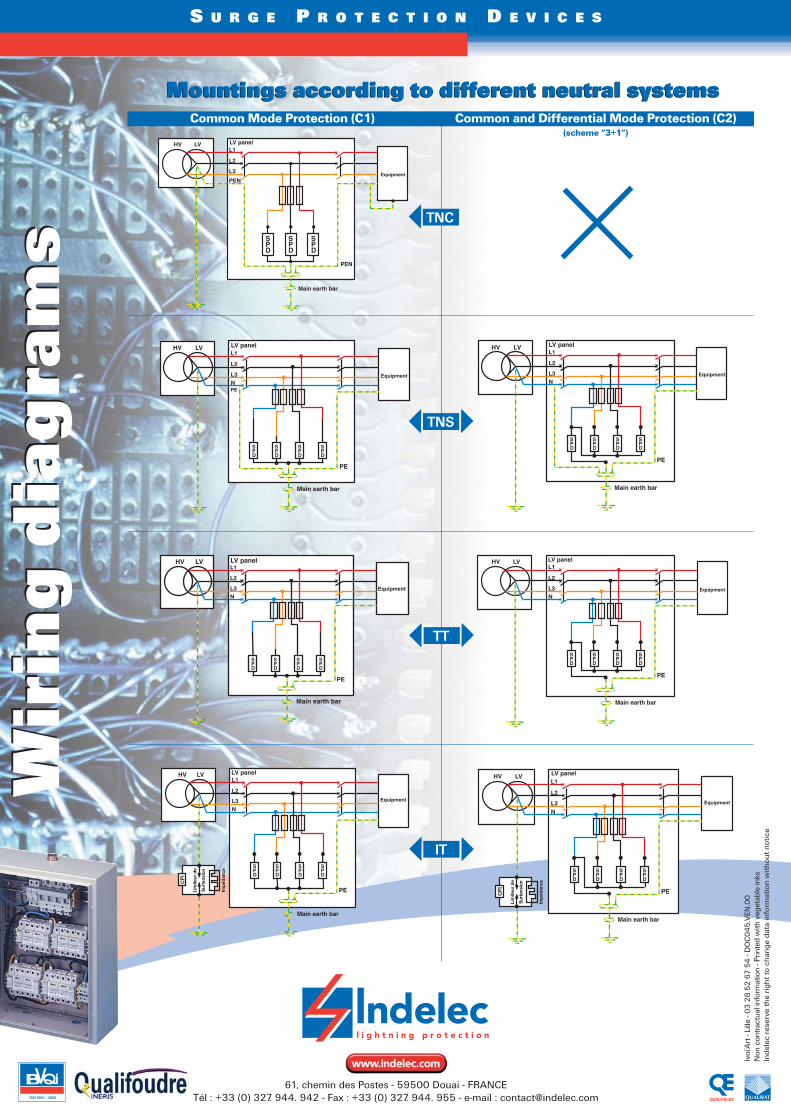
Mountings according to different neutral systemsMountings according to different neutral systemsCommon and Differential Mode Protection (C2)
(scheme “3+1”)
Common Mode Protection (C1)
TNC
TNS
TT
IT
Ivoi
’Art
- Li
lle -
03
28
52
67
54
- D
OC
04
5.V
EN.0
0N
on c
ontr
actu
al in
form
atio
n - P
rinte
d w
ith v
eget
able
inks
Inde
lec
rese
rve
the
righ
t to
cha
nge
data
info
rmat
ion
with
out
notic
e
Wir
ing
dia
gra
ms
Wir
ing
dia
gra
ms