EVALUATION OF THE CLIMBING DRUM PEEL (CDP ... Daghia and Christophe Cluzel C D C Δθ Δu d Δu r 2...
7
20 th International Conference on Composite Materials Copenhagen, 19-24 th July 2015 EVALUATION OF THE CLIMBING DRUM PEEL (CDP) TEST FOR THE DETERMINATION OF THE MODE I FRACTURE TOUGHNESS OF MONOLITHIC LAMINATED COMPOSITE SPECIMENS Federica Daghia 1 and Christophe Cluzel 1,2 1 LMT-Cachan/ENS-Cachan/CNRS/Université Paris Saclay 61 avenue du Président Wilson, 94235 Cachan Cedex, France Email: [email protected], web page: http://www.lmt.ens-cachan.fr 2 IUT d'Evry Val d'Essonne, Département SGM, Bâtiment Maupertuis 3 rue du Père Jarlan, 91025 Evry Cedex, France Email: [email protected] Keywords: Climbing Drum Peel test, Delamination, Mode I fracture toughness ABSTRACT The inter-laminar fracture toughness is a measure of the delamination resistance of a laminated composite system. Its rigorous experimental evaluation requires a number of precautions in the choice of the test setup and post-treatment. In this paper, we consider two different tests for the mode I fracture toughness: the classical Double Cantilever Beam (DCB) test and the Climbing Drum Peel (CDP) test, which is standard in the "adhesives" community and which is first applied here to monolithic composite specimens. The two tests are compared in terms of setup, post-treatment and results on different types of specimens. The CDP appears to have a number of advantages over the DCB, and thus it represents an interesting alternative for the determination of the mode I fracture toughness. 1 INTRODUCTION Delamination, that is the creation and propagation of cracks between the layers of a laminated composite, is a particularly dangerous failure mode for composite structures. The fracture toughness of inter-ply interfaces is an important parameter which enables one to compare the delamination resistance of different composite systems and to predict the failure mode and the failure load through modeling and numerical simulations. A number of experimental configurations exist in the literature to determine the experimental fracture toughness, or critical strain energy release rate, according to different crack propagation modes. The standard mode I test is the Double Cantilever Beam (DCB) [1,2]: although its principle and setup may appear rather simple, it requires a number of precautions in the test setup and post- treatment in order to obtain meaningful results. In particular, the experimental measurement of the crack tip position during propagation is fastidious and delicate to obtain with a satisfying precision with standard experimental techniques; furthermore, the hypotheses which are behind the classical post-treatment of DCB tests are generally based on beam theory and on a linear elastic material, and thus may not reflect correctly the experimental reality for some non-standard test configurations. In this work, we propose to evaluate the Climbing Drum Peel (CDP) test as an alternative to the DCB test for the determination of the mode I fracture toughness of monolithic composite specimens. The CDP test is a standard test in the "adhesives" community [3], where the peel torque associated to a specific geometry of the test setup is used as a measure of the bond strength between a flexible and a rigid adherend (or between the skin and the core of sandwich structures). An energy interpretation and a small modification in the post-treatment of the test enable one to obtain an experimental critical strain energy release rate [4,5]. To the authors' knowledge, our work is the first application of this test to monolithic composite specimens [6,7].
Transcript of EVALUATION OF THE CLIMBING DRUM PEEL (CDP ... Daghia and Christophe Cluzel C D C Δθ Δu d Δu r 2...
20th International Conference on Composite Materials Copenhagen, 19-24th July 2015
EVALUATION OF THE CLIMBING DRUM PEEL (CDP) TEST FOR THE DETERMINATION OF THE MODE I FRACTURE TOUGHNESS OF MONOLITHIC
LAMINATED COMPOSITE SPECIMENS
Federica Daghia1 and Christophe Cluzel1,2
1LMT-Cachan/ENS-Cachan/CNRS/Université Paris Saclay 61 avenue du Président Wilson, 94235 Cachan Cedex, France
Email: [email protected], web page: http://www.lmt.ens-cachan.fr
2IUT d'Evry Val d'Essonne, Département SGM, Bâtiment Maupertuis 3 rue du Père Jarlan, 91025 Evry Cedex, France
Email: [email protected]
Keywords: Climbing Drum Peel test, Delamination, Mode I fracture toughness
ABSTRACT
The inter-laminar fracture toughness is a measure of the delamination resistance of a laminated composite system. Its rigorous experimental evaluation requires a number of precautions in the choice of the test setup and post-treatment. In this paper, we consider two different tests for the mode I fracture toughness: the classical Double Cantilever Beam (DCB) test and the Climbing Drum Peel (CDP) test, which is standard in the "adhesives" community and which is first applied here to monolithic composite specimens. The two tests are compared in terms of setup, post-treatment and results on different types of specimens. The CDP appears to have a number of advantages over the DCB, and thus it represents an interesting alternative for the determination of the mode I fracture toughness.
1 INTRODUCTION
Delamination, that is the creation and propagation of cracks between the layers of a laminated composite, is a particularly dangerous failure mode for composite structures. The fracture toughness of inter-ply interfaces is an important parameter which enables one to compare the delamination resistance of different composite systems and to predict the failure mode and the failure load through modeling and numerical simulations.
A number of experimental configurations exist in the literature to determine the experimental fracture toughness, or critical strain energy release rate, according to different crack propagation modes. The standard mode I test is the Double Cantilever Beam (DCB) [1,2]: although its principle and setup may appear rather simple, it requires a number of precautions in the test setup and post-treatment in order to obtain meaningful results. In particular, the experimental measurement of the crack tip position during propagation is fastidious and delicate to obtain with a satisfying precision with standard experimental techniques; furthermore, the hypotheses which are behind the classical post-treatment of DCB tests are generally based on beam theory and on a linear elastic material, and thus may not reflect correctly the experimental reality for some non-standard test configurations.
In this work, we propose to evaluate the Climbing Drum Peel (CDP) test as an alternative to the DCB test for the determination of the mode I fracture toughness of monolithic composite specimens. The CDP test is a standard test in the "adhesives" community [3], where the peel torque associated to a specific geometry of the test setup is used as a measure of the bond strength between a flexible and a rigid adherend (or between the skin and the core of sandwich structures). An energy interpretation and a small modification in the post-treatment of the test enable one to obtain an experimental critical strain energy release rate [4,5]. To the authors' knowledge, our work is the first application of this test to monolithic composite specimens [6,7].
Federica Daghia and Christophe Cluzel
C
D
C
ΔθΔu d
Δu
r 2
specimen
loadingstraps
drum
r 1
D
Δu tspecimen
u
A
Ba
Forc
e
Displacement
Winding
Winding + Delamination
ΔE
Fd
Fw
Δu
Forc
e
Displacement
ΔE
DCB test principle CDP test principle
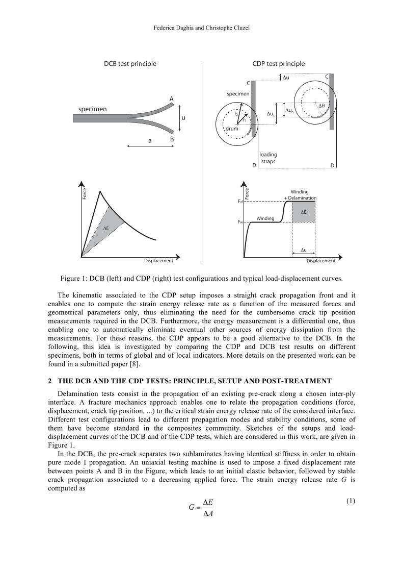
Figure 1: DCB (left) and CDP (right) test configurations and typical load-displacement curves.
The kinematic associated to the CDP setup imposes a straight crack propagation front and it enables one to compute the strain energy release rate as a function of the measured forces and geometrical parameters only, thus eliminating the need for the cumbersome crack tip position measurements required in the DCB. Furthermore, the energy measurement is a differential one, thus enabling one to automatically eliminate eventual other sources of energy dissipation from the measurements. For these reasons, the CDP appears to be a good alternative to the DCB. In the following, this idea is investigated by comparing the CDP and DCB test results on different specimens, both in terms of global and of local indicators. More details on the presented work can be found in a submitted paper [8]. 2 THE DCB AND THE CDP TESTS: PRINCIPLE, SETUP AND POST-TREATMENT
Delamination tests consist in the propagation of an existing pre-crack along a chosen inter-ply interface. A fracture mechanics approach enables one to relate the propagation conditions (force, displacement, crack tip position, ...) to the critical strain energy release rate of the considered interface. Different test configurations lead to different propagation modes and stability conditions, some of them have become standard in the composites community. Sketches of the setups and load-displacement curves of the DCB and of the CDP tests, which are considered in this work, are given in Figure 1.
In the DCB, the pre-crack separates two sublaminates having identical stiffness in order to obtain pure mode I propagation. An uniaxial testing machine is used to impose a fixed displacement rate between points A and B in the Figure, which leads to an initial elastic behavior, followed by stable crack propagation associated to a decreasing applied force. The strain energy release rate G is computed as
G =ΔEΔA
(1)
20th International Conference on Composite Materials Copenhagen, 19-24th July 2015
where ΔE is the released energy (in grey in the Figure) and ΔA is the increase in the cracked area. The expression for G as a function of the force, displacement and crack tip position measurements is generally obtained through a simple beam model, assuming a straight crack front and no sources of energy release or dissipation other than the crack propagation. If significant energy dissipation occurs within the plies, therefore, the classical post-treatment of the DCB test overestimates the critical fracture toughness of the interface, and further experimental tests and computations are required to evaluate and remove the plies' contributions to the dissipation from the test results.
In the CDP, the pre-crack separates two sublaminates having very different stiffness. The flexible part is wound around the internal radius of a drum, which climbs along the specimen thanks to an imposed displacement rate between points C and D in the Figure. Two constant force plateaux are observed as the drum climbs along the specimen: the first corresponds to the energy required to lift the drum and to wind the flexible sublaminate to a constant curvature, while the second includes the energy associated to propagation of the delamination crack. The energy released by delamination, in grey in the Figure, is obtained by difference between the two force plateaux, which enables one to directly exclude the eventual dissipation within the peel arm from the energy balance. Furthermore, if conformity between the drum and the peel arm is ensured, the crack propagation front is straight and the position of the crack tip can be related to the imposed displacement only through geometrical parameters of the specimen and of the setup. For this reason, only the values of the forces corresponding to the two plateaux and some geometrical parameters are required to compute the strain energy release rate [4,5].
3 DESIGN OF THE STACKING SEQUENCES FOR DCB AND CDP TESTS
The DCB test standards [1,2] prescribes the use of a [0]n stacking sequence with a pre-crack positioned in the laminate's midplane. A number of literature works, on the other hand, considered different stacking sequences in order to evaluate the effect of the fiber directions in the adjacent plies on the interface fracture toughness. The definition of the stacking sequence, however, should respect a number of criteria. In particular, the membrane and bending behaviors of the whole laminate and of each sublaminate should be uncoupled to avoid the release of thermal residual stresses during crack propagation. Furthermore, tensile/shear and flexion/torsion uncoupling should be guaranteed in order to ensure the symmetry of the crack propagation with respect to the longitudinal axis of the specimen. Finally, the anticlastic curvature should be small, since it is at the origin of the non-straight shape of the crack front during propagation which may be observed in DCB specimens. Analogous recommendations can be defined for CDP specimens.
Three stacking sequences were defined for unidirectional plies, based on [9]: • [0/902/0]6 • [0/902/0/90/02/90/90/02/90]2 • [45/-452/45/-45/452/-45]4
In each sequence, the pre-crack for the DCB specimens should be positioned in the midplane of the specimen, while the pre-crack for the CDP specimen should be positioned after the fourth unidirectional ply, according to the stiffness requirements associated to each test. The three defined sequences enable us to study interfaces in which the adjacent plies have different orientations with respect to the crack propagation direction: 0/0, 90/0 and +45/-45 respectively.
In this work, 5H Satin woven plies were considered. Due to the asymmetry of the weave pattern with respect to the ply's midplane, a woven satin ply is considered to be equivalent to a 0/90 stack of unidirectional plies. For this reason, the stacking sequences considered for woven plies were
• [(0c/90t)/(90t/0c)]6 • [(0c/90t)/(90t/0c)/(90t/0c)/(0c/90t)/(90t/0c)/(0c/90t)]2 • [(45c/-45t)/(-45t/45c)/(-45t/45c)/(45c/-45t)]4
In these sequences, a woven ply is noted as (θc/(90+θ)t), where the indices c and t indicate the warp and weft yarns (chaine and trame, in French) respectively. This enables one to specify the relative position and orientation of the warp-dominated and the weft-dominated sides of the ply, which is non standard for woven composites manufacturing but which is important to ensure the required symmetries for the tests.
Federica Daghia and Christophe Cluzel
0 10 20 30 400
20
40
60
80
Displacement (mm)
Forc
e (
N)
DCB all interfaces
0/0 interface90/0 interface45/−45 interface
0 10 20 30 40 500
50
100
150
200
250
Displacement (mm)
Forc
e (
N)
CDP all interfaces
0/0 interface90/0 interface45/−45 interface
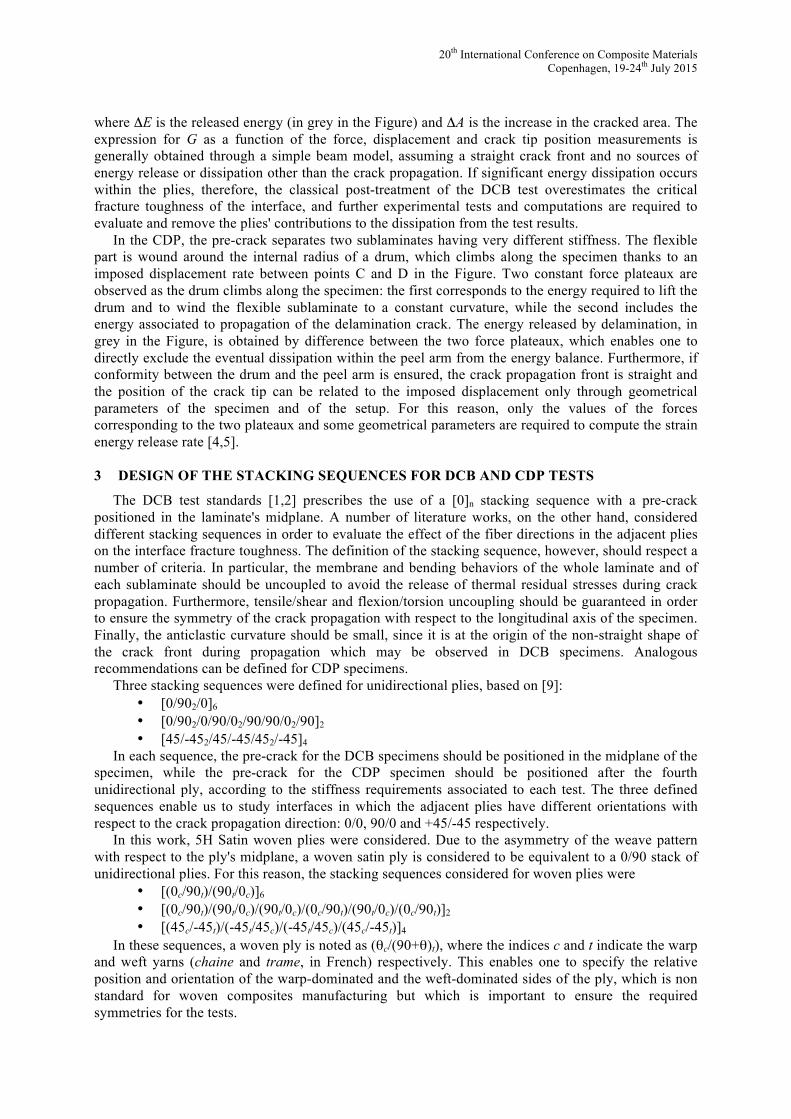
Figure 2: DCB (left) and CDP (right) force-displacement curves for the different kinds of specimens.
0/0 interface 90/0 interface +45/−45 interface0
200
400
600
800
1000
Gc (
J/m
2)
DCB tests
0/0 interface 90/0 interface +45/−45 interface0
200
400
600
800
1000G
c (J/
m2)
CDP tests
Figure 3: DCB (left) and CDP (right) average strain energy release rates for the different kinds of specimens.
4 RESULTS AND DISCUSSION
Both DCB and CDP tests were carried out on the stacking sequences discussed in Section 3. The results were compared using both global and local indicators.
Both the DCB and the CDP test results were very repeatable for specimens having the same stacking sequence, while some differences could be noticed across the different types of specimens (see Figure 2, where a curve for each type of specimens is reported). In both cases, propagation occurred by successive instabilities, as it is generally the case for woven composites: the crack increment associated to each instability was well correlated to the size of the weave pattern, thus indicating local toughness differences across the interfaces. In order to account for the actual energy released at each propagation step, the discrete strain energy release rate associated to each jump was computed for the DCB specimens. For the CDP specimens, this amounted to using the average, and not the maximum value of the force during the delamination plateau for the calculation of the strain energy release rate.
The average critical strain energy release rates for the different kinds of specimens as determined by DCB and CDP tests are reported in Figure 3. While the results of the two kind of tests were analogous for the 90/0 and for the +45/-45 interface specimens, a significant difference can be observed for the 0/0 specimen results. The CDP 0/0 critical strain energy release rate is similar to the one obtained for the CDP 90/0 and for the DCB 90/0, while the DCB 0/0 value is much lower. For both types of tests, the +45/-45 interface specimens yielded much higher values of the critical strain energy release rate as compared to the other types of specimens.
20th International Conference on Composite Materials Copenhagen, 19-24th July 2015
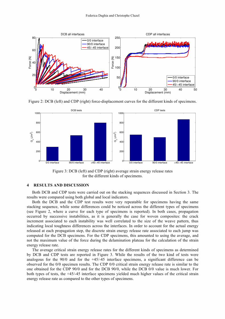
Figure 4: Fracture surfaces for the 0/0 interface specimens tested by DCB (left) and CDP (right).
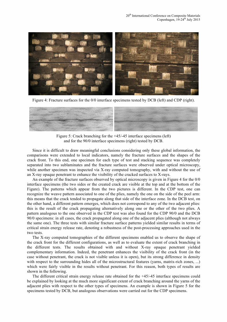
Figure 5: Crack branching for the +45/-45 interface specimens (left)
and for the 90/0 interface specimens (right) tested by DCB.
Since it is difficult to draw meaningful conclusions considering only these global information, the comparisons were extended to local indicators, namely the fracture surfaces and the shapes of the crack front. To this end, one specimen for each type of test and stacking sequence was completely separated into two sublaminates and the fracture surfaces were observed under optical microscopy, while another specimen was inspected via X-ray computed tomography, with and without the use of an X-ray opaque penetrant to enhance the visibility of the cracked surfaces to X-rays.
An example of the fracture surfaces observed by optical microscopy is given in Figure 4 for the 0/0 interface specimens (the two sides or the created crack are visible at the top and at the bottom of the Figure). The patterns which appear from the two pictures is different. In the CDP test, one can recognize the weave pattern associated to one of the plies, namely the one on the side of the peel arm: this means that the crack tended to propagate along that side of the interface zone. In the DCB test, on the other hand, a different pattern emerges, which does not correspond to any of the two adjacent plies: this is the result of the crack propagating alternatively along one or the other of the two plies. A pattern analogous to the one observed in the CDP test was also found for the CDP 90/0 and the DCB 90/0 specimens: in all cases, the crack propagated along one of the adjacent plies (although not always the same one). The three tests with similar fracture surface patterns yielded similar results in terms of critical strain energy release rate, denoting a robustness of the post-processing approaches used in the two tests.
The X-ray computed tomographies of the different specimens enabled us to observe the shape of the crack front for the different configurations, as well as to evaluate the extent of crack branching in the different tests. The results obtained with and without X-ray opaque penetrant yielded complementary information. Indeed, the penetrant enhances the visibility of the crack front (in the case without penetrant, the crack is not visible unless it is open), but its strong difference in density with respect to the surrounding hides all of the microstructural features (yarns, matrix-rich zones, ...) which were fairly visible in the results without penetrant. For this reason, both types of results are shown in the following.
The different critical strain energy release rate obtained for the +45/-45 interface specimens could be explained by looking at the much more significant extent of crack branching around the yarns of the adjacent plies with respect to the other types of specimens. An example is shown in Figure 5 for the specimens tested by DCB, but analogous observations were carried out for the CDP specimens.
Federica Daghia and Christophe Cluzel
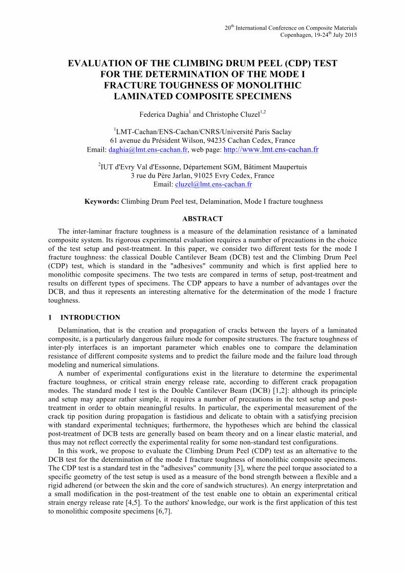
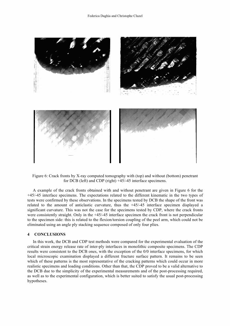
Figure 6: Crack fronts by X-ray computed tomography with (top) and without (bottom) penetrant for DCB (left) and CDP (right) +45/-45 interface specimens.
A example of the crack fronts obtained with and without penetrant are given in Figure 6 for the +45/-45 interface specimens. The expectations related to the different kinematic in the two types of tests were confirmed by these observations. In the specimens tested by DCB the shape of the front was related to the amount of anticlastic curvature, thus the +45/-45 interface specimen displayed a significant curvature. This was not the case for the specimens tested by CDP, where the crack fronts were consistently straight. Only in the +45/-45 interface specimen the crack front is not perpendicular to the specimen side: this is related to the flexion/torsion coupling of the peel arm, which could not be eliminated using an angle ply stacking sequence composed of only four plies.
4 CONCLUSIONS
In this work, the DCB and CDP test methods were compared for the experimental evaluation of the critical strain energy release rate of inter-ply interfaces in monolithic composite specimens. The CDP results were consistent to the DCB ones, with the exception of the 0/0 interface specimens, for which local microscopic examination displayed a different fracture surface pattern. It remains to be seen which of these patterns is the most representative of the cracking patterns which could occur in more realistic specimens and loading conditions. Other than that, the CDP proved to be a valid alternative to the DCB due to the simplicity of the experimental measurements and of the post-processing required, as well as to the experimental configuration, which is better suited to satisfy the usual post-processing hypotheses.
20th International Conference on Composite Materials Copenhagen, 19-24th July 2015
ACKNOWLEDGEMENTS
This work has been financially supported by the French "Agence Nationale de la Recherche'', through the "Investissements d’avenir'' program (ANR-10-EQPX-37 MATMECA Grant). The authors would like to acknowledge Xavier Fayolle and Benjamin Smaniotto for their help with the experimental setup and X-ray tomography acquisitions.
REFERENCES
[1] ISO-15024. Fibre-reinforced plastic composites - determination of the mode I interlaminar fracture toughness, GIc, for unidirectionally reinforced materials.
[2] ASTM-D5528. Standard test method for mode I interlaminar fracture toughness of unidirectional fiber-reinforced polymer matrix composites.
[3] ASTM-D1781. Standard test method for climbing drum peel for adhesives. [4] R. Okada and M. T. Kortschot, The role of the resin fillet in the delamination of honeycomb
sandwich structures, Composites Science and Technology, 62, 2002, pp.1811-1819. [5] A. T. Nettles, E. D. Gregory and J. R. Jackson, Using the climbing drum peel (CDP) test to
obtain a GIC value for core/face sheet bonds, Journal of Composite Materials, 41, 2007, pp. 2863-2876.
[6] F. Daghia and C. Cluzel, An oxidation/delamination test for laminated composites with organic matrix (in French), Compte Rendus des JNC18, Nantes, France, June 12-14, 2013.
[7] F. Daghia and C. Cluzel, Experimental study on the propagation of delamination under oxidizing environment and mechanical loading, Proceedings of ECCM16 - 16th European Conference on Composite Materials, Seville, Spain, June 22-26, 2014.
[8] F. Daghia and C. Cluzel, The Climbing Drum Peel test: an alternative to the Double Cantilever Beam for the determination of fracture toughness of monolithic laminates, submitted.
[9] X. J. Gong, A. Hurez and G. Verchery, On the determination of delamination toughness by using multidirectional DCB specimens, Polymer testing, 29, 2010, pp. 658-666.