Evaluation and comparison of classical earth pressure ...
19
www.ijcrt.org © 2017 IJCRT | Volume 5, Issue 4 December 2017 | ISSN: 2320-2882 IJCRT1704227 International Journal of Creative Research Thoughts (IJCRT) www.ijcrt.org 1775 Evaluation and comparison of classical earth pressure theories for cohesion-less (φ) backfill using professional softwares 1 Pinki Sharma, 1 Assistant Professor, 1 M S Patel Department of Civil Engineering, 1 Charotar University of Science and Technology-CHARUSAT, Changa-Anand, India ________________________________________________________________________________________________________ Abstract: Earth pressure related problems are one of the important topics of research in the area of geotechnical engineering to solve problems like retaining walls, ground anchors etc. Very often in the construction of building or bridges it is necessary to retain earth in a relatively vertical position whenever embankments are involved in the construction. The retaining material on the higher level exerts a force on retaining wall may causes its overturning, sliding, bearing etc. A retaining wall is massive structure so it is necessary to design and check stability of retaining wall analytically as well by software as per IS:456-2000. The calculation of wall dimension of particular earth retaining problem require several runs of analysis and thus computer application is desirable. The present research deals with evaluation of cantilever retaining wall by comparison of Excel worksheet & softwares Geo-5, RetainPro & RETWALL for single layered homogeneous φ soil backfill with and without ground water table. The MS-Excel Spreadsheet is to be prepared to carry out stability analysis. The analysis of Retaining wall can be done by using various static earth pressure theories such as Rankine, Coulomb's. Factory of safety against sliding, overturning and base pressure are satisfied without considering shear key & with provision of shear key. Index Terms— Cantilever retaining wall, Professional softwares, Single layered homogeneous φ soil backfill ________________________________________________________________________________________________________ I. INTRODUCTION Retaining walls are structures that are used to retain earth (or any other material) in a position where the ground level changes abruptly. They can be of many types such as gravity wall, cantilever wall, counterfort wall and buttress wall among others. The lateral force due to earth pressure is the main force that acts on the retaining wall which has the tendency to bend, slide and overturn it. The present research focuses on stability analysis of the cantilever type of wall for overturning, sliding and bearing. The main considerations are the external stability of the section with the help of codal provision i.e. IS: 456:2000 Satisfying the external stability criteria is primarily based on the section giving the required factor of safety. The ratio of resisting forces to the disturbing forces is the factor of safety, and this factor of safety should always be greater and equal to 1.55 for the structure to be safe against failure with respect to that particular criteria. Different modes of failure have different factors of safety. In this study stability check for a cantilever wall is obtained using a computer program that calculates various sections satisfying the stability criteria, according to the height and properties of earth that the wall is required to support. Retaining walls are structures designed to restrain soil to unnatural slopes. They are used to bound soils between two different elevations often in areas of terrain possessing undesirable slopes or in areas where the landscape needs to be shaped severely and engineered for more specific purposes like hillside farming or roadway overpasses. It is a structure designed and constructed to resist the lateral pressure of soil when there is a desired change in ground elevation that exceeds the angle of repose of the soil. In general, two classical methods of analysis have been proposed for evaluation of retaining wall. 1.Rankine earth pressure theory: Rankine earth pressure is a state of stress evaluation of soil behind a retaining structure that traditionally assumes a vertical wall and no fiction between the soil/wall interfaces. The orientation of the resultant earth pressure is parallel to the back slope surface. 2. Coulomb’s earth pressure theory: In Coulomb theory Coulomb failure plane varies as a function of wall geometry and wall friction between soil/wall interfaces is taken into account. Due to the rapid development of increasingly powerful computers, the solution of rather complex multi-phase problems encountered in widely different fields of engineering tasks is feasible nowadays. Nowadays, the numbers of software in the market is growing. Software is developed to help users in making their task easier. We can find different software for different business processes. In Geotechnical Engineering, there are few softwares which can be bought in the market. For example Geo-5, RetainPro, RETWALL, iCadRetaining wall Software and many more but in this study we are going to carryout evaluation of cantilever retaining wall by comparison by softwares Geo-5, RetainPro & RETWALL.
Transcript of Evaluation and comparison of classical earth pressure ...
www.ijcrt.org © 2017 IJCRT | Volume 5, Issue 4 December 2017 | ISSN: 2320-2882
IJCRT1704227 International Journal of Creative Research Thoughts (IJCRT) www.ijcrt.org 1775
Evaluation and comparison of classical earth
pressure theories for cohesion-less (φ) backfill
using professional softwares 1Pinki Sharma,
1Assistant Professor, 1M S Patel Department of Civil Engineering,
1Charotar University of Science and Technology-CHARUSAT, Changa-Anand, India ________________________________________________________________________________________________________
Abstract: Earth pressure related problems are one of the important topics of research in the area of geotechnical engineering to
solve problems like retaining walls, ground anchors etc. Very often in the construction of building or bridges it is necessary to
retain earth in a relatively vertical position whenever embankments are involved in the construction. The retaining material on the
higher level exerts a force on retaining wall may causes its overturning, sliding, bearing etc. A retaining wall is massive structure
so it is necessary to design and check stability of retaining wall analytically as well by software as per IS:456-2000. The
calculation of wall dimension of particular earth retaining problem require several runs of analysis and thus computer application
is desirable. The present research deals with evaluation of cantilever retaining wall by comparison of Excel worksheet &
softwares Geo-5, RetainPro & RETWALL for single layered homogeneous φ soil backfill with and without ground water table.
The MS-Excel Spreadsheet is to be prepared to carry out stability analysis. The analysis of Retaining wall can be done by using
various static earth pressure theories such as Rankine, Coulomb's. Factory of safety against sliding, overturning and base pressure
are satisfied without considering shear key & with provision of shear key.
Index Terms— Cantilever retaining wall, Professional softwares, Single layered homogeneous φ soil backfill ________________________________________________________________________________________________________
I. INTRODUCTION
Retaining walls are structures that are used to retain earth (or any other material) in a position where the ground level changes
abruptly. They can be of many types such as gravity wall, cantilever wall, counterfort wall and buttress wall among others. The
lateral force due to earth pressure is the main force that acts on the retaining wall which has the tendency to bend, slide and overturn
it. The present research focuses on stability analysis of the cantilever type of wall for overturning, sliding and bearing. The main
considerations are the external stability of the section with the help of codal provision i.e. IS: 456:2000 Satisfying the external
stability criteria is primarily based on the section giving the required factor of safety. The ratio of resisting forces to the disturbing
forces is the factor of safety, and this factor of safety should always be greater and equal to 1.55 for the structure to be safe against
failure with respect to that particular criteria. Different modes of failure have different factors of safety. In this study stability check
for a cantilever wall is obtained using a computer program that calculates various sections satisfying the stability criteria, according
to the height and properties of earth that the wall is required to support.
Retaining walls are structures designed to restrain soil to unnatural slopes. They are used to bound soils between two different
elevations often in areas of terrain possessing undesirable slopes or in areas where the landscape needs to be shaped severely and
engineered for more specific purposes like hillside farming or roadway overpasses. It is a structure designed and constructed to
resist the lateral pressure of soil when there is a desired change in ground elevation that exceeds the angle of repose of the soil.
In general, two classical methods of analysis have been proposed for evaluation of retaining wall.
1. Rankine earth pressure theory:
Rankine earth pressure is a state of stress evaluation of soil behind a retaining structure that traditionally assumes a vertical
wall and no fiction between the soil/wall interfaces. The orientation of the resultant earth pressure is parallel to the back
slope surface.
2. Coulomb’s earth pressure theory:
In Coulomb theory Coulomb failure plane varies as a function of wall geometry and wall friction between soil/wall
interfaces is taken into account.
Due to the rapid development of increasingly powerful computers, the solution of rather complex multi-phase problems
encountered in widely different fields of engineering tasks is feasible nowadays. Nowadays, the numbers of software in the market
is growing. Software is developed to help users in making their task easier. We can find different software for different business
processes. In Geotechnical Engineering, there are few softwares which can be bought in the market. For example Geo-5, RetainPro,
RETWALL, iCadRetaining wall Software and many more but in this study we are going to carryout evaluation of cantilever
retaining wall by comparison by softwares Geo-5, RetainPro & RETWALL.
www.ijcrt.org © 2017 IJCRT | Volume 5, Issue 4 December 2017 | ISSN: 2320-2882
IJCRT1704227 International Journal of Creative Research Thoughts (IJCRT) www.ijcrt.org 1776
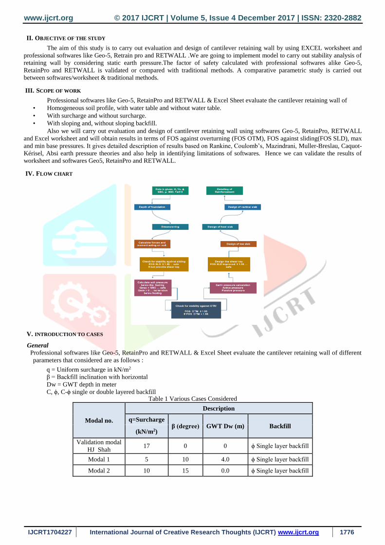
II. OBJECTIVE OF THE STUDY
The aim of this study is to carry out evaluation and design of cantilever retaining wall by using EXCEL worksheet and
professional softwares like Geo-5, Retrain pro and RETWALL .We are going to implement model to carry out stability analysis of
retaining wall by considering static earth pressure.The factor of safety calculated with professional softwares alike Geo-5,
RetainPro and RETWALL is validated or compared with traditional methods. A comparative parametric study is carried out
between softwares/worksheet & traditional methods.
III. SCOPE OF WORK
Professional softwares like Geo-5, RetainPro and RETWALL & Excel Sheet evaluate the cantilever retaining wall of
• Homogeneous soil profile, with water table and without water table.
• With surcharge and without surcharge.
• With sloping and, without sloping backfill.
Also we will carry out evaluation and design of cantilever retaining wall using softwares Geo-5, RetainPro, RETWALL
and Excel worksheet and will obtain results in terms of FOS against overturning (FOS OTM), FOS against sliding(FOS SLD), max
and min base pressures. It gives detailed description of results based on Rankine, Coulomb’s, Mazindrani, Muller-Breslau, Caquot-
Kérisel, Absi earth pressure theories and also help in identifying limitations of softwares. Hence we can validate the results of
worksheet and softwares Geo5, RetainPro and RETWALL.
IV. FLOW CHART
V. INTRODUCTION TO CASES
General
Professional softwares like Geo-5, RetainPro and RETWALL & Excel Sheet evaluate the cantilever retaining wall of different
parameters that considered are as follows :
q = Uniform surcharge in kN/m2
β = Backfill inclination with horizontal
Dw = GWT depth in meter
C, ϕ, C-ϕ single or double layered backfill Table 1 Various Cases Considered
Modal no.
Description
q=Surcharge β (degree) GWT Dw (m) Backfill
(kN/m2)
Validation modal
HJ Shah 17 0 0 ϕ Single layer backfill
Modal 1 5 10 4.0 ϕ Single layer backfill
Modal 2 10 15 0.0 ϕ Single layer backfill
www.ijcrt.org © 2017 IJCRT | Volume 5, Issue 4 December 2017 | ISSN: 2320-2882
IJCRT1704227 International Journal of Creative Research Thoughts (IJCRT) www.ijcrt.org 1777
Validity of Softwares
It is necessary to validate the computer software by checking the output result of the computer software. Hence, it is
important to validate the Geo-5, RetainPro, RETWALL software before we can really apply to solving problem. To validate the
Geo-5, RETAIN – PRO, RETWALL, an example from known sources with an answer is used to analyze with the Geo-5,
RetainPro, RETWALL. The importance of the process to validate the software is :
To confirm and to know that the process of inputting data is correct.
To ensure and be able to correctly interpret the computer data and understand enough the procedure of using the
software.
To satisfy that software will give the correct answer.
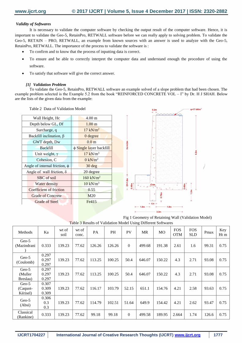
[1] Validation Problem
To validate the Geo-5, RetainPro, RETWALL software an example solved of a slope problem that had been chosen. The
example problem selected is the Example 5.2 from the book “REINFORCED CONCRETE VOL – I” by Dr. H J SHAH. Below
are the lists of the given data from the example:
Table 2 Data of Validation Model
Wall Height, Hc 4.00 m
Depth below GL, Df 1.00 m
Surcharge, q 17 kN/m2
Backfill inclination, β 0 degree
GWT depth, Dw 0.0 m
Backfill ϕ Single layer backfill
Unit weight, γ 17 kN/m3
Cohesion, C 0 kN/m2
Angle of internal friction, ϕ 30 deg
Angle of wall friction, δ 20 degree
SBC of soil 160 kN/m2
Water density 10 kN/m3
Coefficient of friction 0.55
Grade of Concrete M20
Grade of Steel Fe415
Fig 1 Geometry of Retaining Wall (Validation Model)
Table 3 Results of Validation Model Using Different Softwares
Methods Ka wt of
soil
wt of
conc. PA PH PV MR MO
FOS
OTM
FOS
SLD Pmax
Key
Ht m
Geo-5
(Mazindrani
)
0.333 139.23 77.62 126.26 126.26 0 499.68 191.38 2.61 1.6 99.31 0.75
Geo-5
(Coulomb)
0.297
0.297
0.297
139.23 77.62 113.25 100.25 50.4 646.07 150.22 4.3 2.71 93.08 0.75
Geo-5
(Muller
Breslau)
0.297
0.297
0.297
139.23 77.62 113.25 100.25 50.4 646.07 150.22 4.3 2.71 93.08 0.75
Geo-5
(Caquot-
Kérisel)
0.307
0.309
0.309
139.23 77.62 116.17 103.79 52.15 651.1 154.76 4.21 2.58 93.63 0.75
Geo-5
(Absi)
0.306
0.3
0.3
139.23 77.62 114.79 102.51 51.64 649.9 154.42 4.21 2.62 93.47 0.75
Classical
(Rankine) 0.333 139.23 77.62 99.18 99.18 0 499.58 189.95 2.664 1.74 126.6 0.75
www.ijcrt.org © 2017 IJCRT | Volume 5, Issue 4 December 2017 | ISSN: 2320-2882
IJCRT1704227 International Journal of Creative Research Thoughts (IJCRT) www.ijcrt.org 1778
Classical
(coulomb) 0.297 139.23 77.62 83.03 83.03 0 596.38 158.15 3.77 1.84 107.9 0.75
Excel
worksheet
(Rankine)
0.333 139.23 70.13 99.18 99.18 0 490.68 188.89 2.6 1.55 123.1 0
Excel
worksheet
(coulomb)
0.297 139.23 70.13 83.03 83.03 0 587.38 158.15 3.71 1.55 86.22 0
RetainPro
(Rankine) 0.333 146.27 77.62 99.03 99.03 0 471.61 188.53 2.5 1.61 114.6 0.75
RetainPro
(Coulomb) 0.297 146.27 77.62 86.5 86.5 0 471.61 164.67 2.86 1.85 100.6 0.75
RETWALL - - - 99.18 99.18 0 494.14 188.9 2.61 1.67 125 0.75
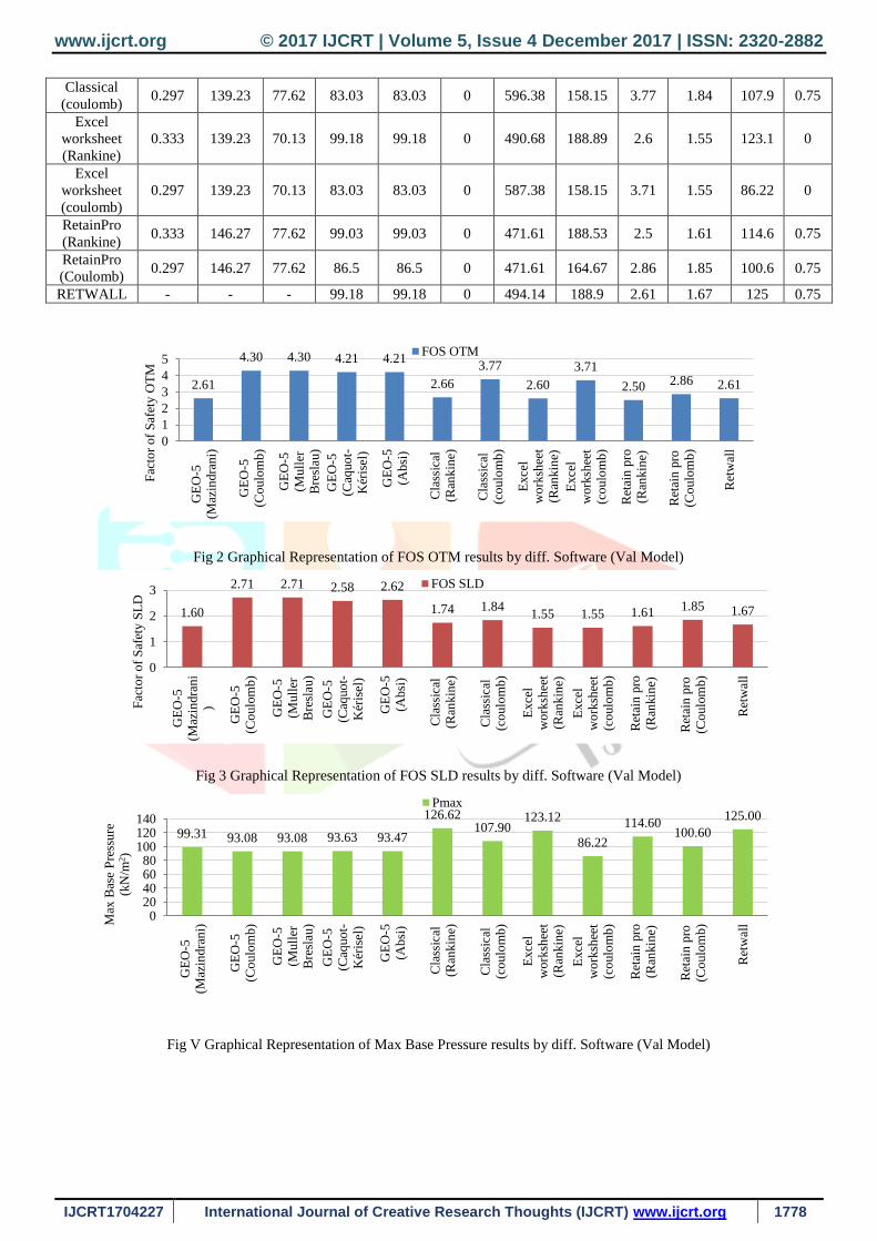
Fig 2 Graphical Representation of FOS OTM results by diff. Software (Val Model)
Fig 3 Graphical Representation of FOS SLD results by diff. Software (Val Model)
Fig V Graphical Representation of Max Base Pressure results by diff. Software (Val Model)
2.61
4.30 4.30 4.21 4.21
2.66
3.77
2.60
3.71
2.50 2.86 2.61
0
1
2
3
4
5
GE
O-5
(Maz
indra
ni)
GE
O-5
(Co
ulo
mb)
GE
O-5
(Mull
er
Bre
slau
)
GE
O-5
(Caq
uo
t-
Kér
isel
)
GE
O-5
(Ab
si)
Cla
ssic
al
(Ran
kin
e)
Cla
ssic
al
(co
ulo
mb)
Exce
l
wo
rksh
eet
(Ran
kin
e)
Exce
l
wo
rksh
eet
(co
ulo
mb)
Ret
ain
pro
(Ran
kin
e)
Ret
ain
pro
(Co
ulo
mb)
Ret
wal
l
Fac
tor
of
Saf
ety O
TM
FOS OTM
1.60
2.71 2.71 2.58 2.62
1.74 1.841.55 1.55 1.61
1.85 1.67
0
1
2
3
GE
O-5
(Maz
indra
ni
)
GE
O-5
(Co
ulo
mb)
GE
O-5
(Mull
er
Bre
slau
)
GE
O-5
(Caq
uo
t-
Kér
isel
)
GE
O-5
(Ab
si)
Cla
ssic
al
(Ran
kin
e)
Cla
ssic
al
(co
ulo
mb)
Exce
l
wo
rksh
eet
(Ran
kin
e)
Exce
l
wo
rksh
eet
(co
ulo
mb)
Ret
ain
pro
(Ran
kin
e)
Ret
ain
pro
(Co
ulo
mb)
Ret
wal
l
Fac
tor
of
Saf
ety S
LD
FOS SLD
99.31 93.08 93.08 93.63 93.47
126.62107.90
123.12
86.22
114.60100.60
125.00
020406080
100120140
GE
O-5
(Maz
indra
ni)
GE
O-5
(Co
ulo
mb)
GE
O-5
(Mull
er
Bre
slau
)
GE
O-5
(Caq
uo
t-
Kér
isel
)
GE
O-5
(Ab
si)
Cla
ssic
al
(Ran
kin
e)
Cla
ssic
al
(co
ulo
mb)
Exce
l
wo
rksh
eet
(Ran
kin
e)
Exce
l
wo
rksh
eet
(co
ulo
mb)
Ret
ain
pro
(Ran
kin
e)
Ret
ain
pro
(Co
ulo
mb)
Ret
wal
lMax
Bas
e P
ress
ure
(kN
/m2)
Pmax
www.ijcrt.org © 2017 IJCRT | Volume 5, Issue 4 December 2017 | ISSN: 2320-2882
IJCRT1704227 International Journal of Creative Research Thoughts (IJCRT) www.ijcrt.org 1779
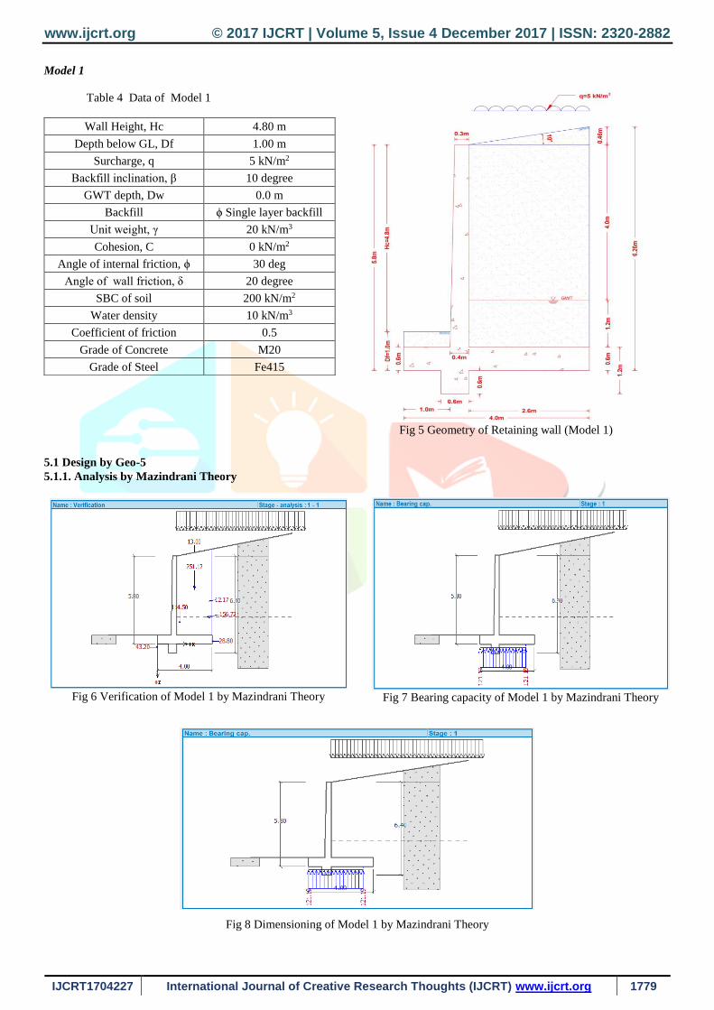
Model 1
5.1 Design by Geo-5
5.1.1. Analysis by Mazindrani Theory
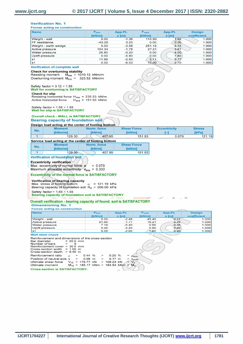
Fig 8 Dimensioning of Model 1 by Mazindrani Theory
Wall Height, Hc 4.80 m
Depth below GL, Df 1.00 m
Surcharge, q 5 kN/m2
Backfill inclination, β 10 degree
GWT depth, Dw 0.0 m
Backfill ϕ Single layer backfill
Unit weight, γ 20 kN/m3
Cohesion, C 0 kN/m2
Angle of internal friction, ϕ 30 deg
Angle of wall friction, δ 20 degree
SBC of soil 200 kN/m2
Water density 10 kN/m3
Coefficient of friction 0.5
Grade of Concrete M20
Grade of Steel Fe415
Table 4 Data of Model 1
Fig 5 Geometry of Retaining wall (Model 1)
Fig 6 Verification of Model 1 by Mazindrani Theory
Fig 7 Bearing capacity of Model 1 by Mazindrani Theory

www.ijcrt.org © 2017 IJCRT | Volume 5, Issue 4 December 2017 | ISSN: 2320-2882
IJCRT1704227 International Journal of Creative Research Thoughts (IJCRT) www.ijcrt.org 1780
www.ijcrt.org © 2017 IJCRT | Volume 5, Issue 4 December 2017 | ISSN: 2320-2882
IJCRT1704227 International Journal of Creative Research Thoughts (IJCRT) www.ijcrt.org 1781
www.ijcrt.org © 2017 IJCRT | Volume 5, Issue 4 December 2017 | ISSN: 2320-2882
IJCRT1704227 International Journal of Creative Research Thoughts (IJCRT) www.ijcrt.org 1782
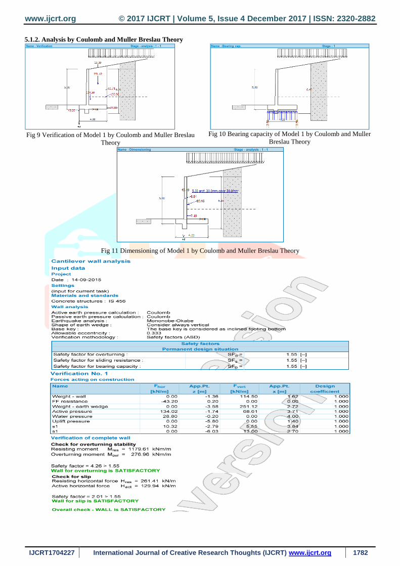
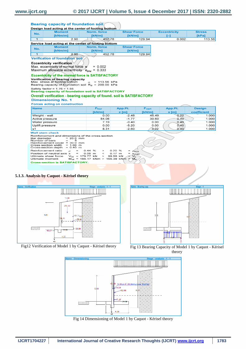
5.1.2. Analysis by Coulomb and Muller Breslau Theory
Fig 9 Verification of Model 1 by Coulomb and Muller Breslau
Theory
Fig 10 Bearing capacity of Model 1 by Coulomb and Muller
Breslau Theory
Fig 11 Dimensioning of Model 1 by Coulomb and Muller Breslau Theory
www.ijcrt.org © 2017 IJCRT | Volume 5, Issue 4 December 2017 | ISSN: 2320-2882
IJCRT1704227 International Journal of Creative Research Thoughts (IJCRT) www.ijcrt.org 1783
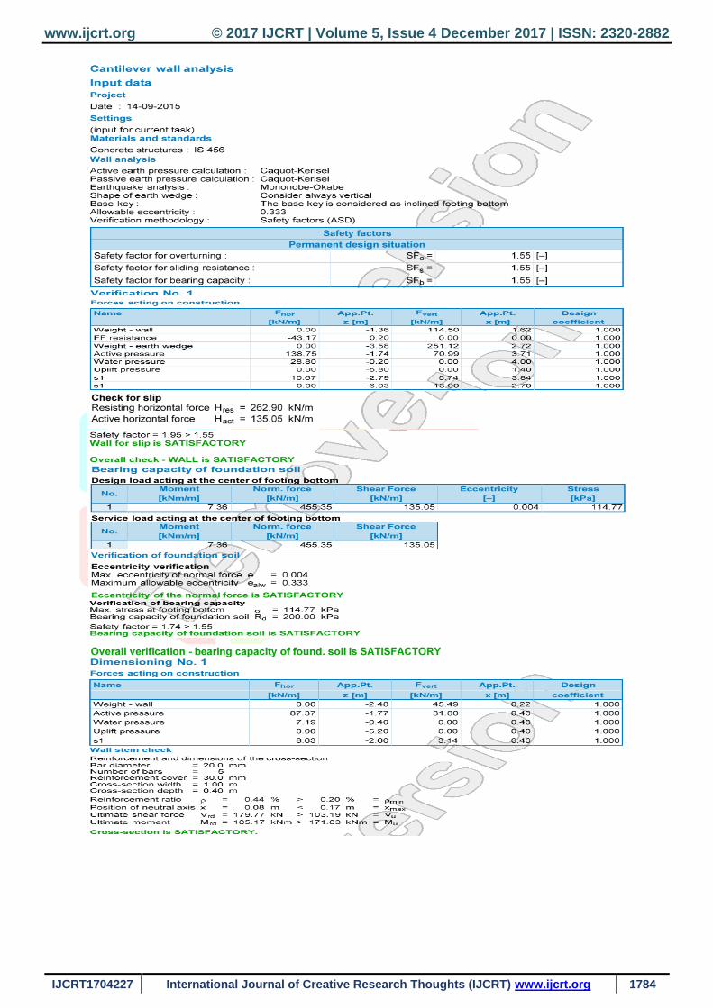
5.1.3. Analysis by Caquot - Kérisel theory
Fig12 Verification of Model 1 by Caquot - Kérisel theory
Fig 13 Bearing Capacity of Model 1 by Caquot - Kérisel
theory
Fig 14 Dimensioning of Model 1 by Caquot - Kérisel theory
www.ijcrt.org © 2017 IJCRT | Volume 5, Issue 4 December 2017 | ISSN: 2320-2882
IJCRT1704227 International Journal of Creative Research Thoughts (IJCRT) www.ijcrt.org 1784
www.ijcrt.org © 2017 IJCRT | Volume 5, Issue 4 December 2017 | ISSN: 2320-2882
IJCRT1704227 International Journal of Creative Research Thoughts (IJCRT) www.ijcrt.org 1785
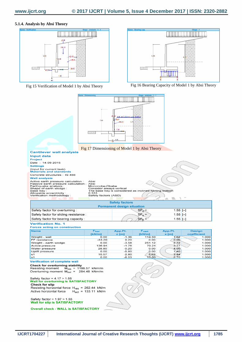
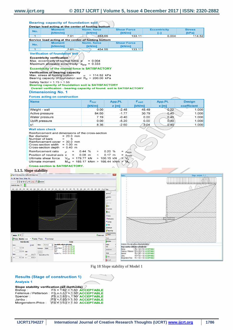
5.1.4. Analysis by Absi Theory
Fig 15 Verification of Model 1 by Absi Theory
Fig 16 Bearing Capacity of Model 1 by Absi Theory
Fig 17 Dimensioning of Model 1 by Absi Theory
www.ijcrt.org © 2017 IJCRT | Volume 5, Issue 4 December 2017 | ISSN: 2320-2882
IJCRT1704227 International Journal of Creative Research Thoughts (IJCRT) www.ijcrt.org 1786
5.1.5. Slope stability
Fig 18 Slope stability of Model 1

www.ijcrt.org © 2017 IJCRT | Volume 5, Issue 4 December 2017 | ISSN: 2320-2882
IJCRT1704227 International Journal of Creative Research Thoughts (IJCRT) www.ijcrt.org 1787
5.2 Design by RetainPro
5.2.1. Analysis by Rankine Theory
Fig 19 Wall construction of Model 1 by
Rankine Theory Fig 20 Wall construction of Model
1 by Rankine Theory
Fig 21 Wall Loading of Model 1 by
Rankine Theory
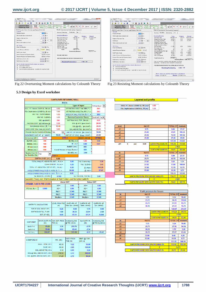
Fig 22 Overturning Moment calculations by Rankine Theory Fig 23 Resisting Moment calculations by Rankine Theory
5.2.2. Analysis by Coulomb Theory
Fig 24 Wall construction of Model 1 by
Coulomb Theory Fig 25 Wall construction of Model
1 by Coulomb Theory
Fig 26 Wall Loading of Model 1 by
Coulomb Theory
www.ijcrt.org © 2017 IJCRT | Volume 5, Issue 4 December 2017 | ISSN: 2320-2882
IJCRT1704227 International Journal of Creative Research Thoughts (IJCRT) www.ijcrt.org 1788
Fig 22 Overturning Moment calculations by Coloumb Theory Fig 23 Resisting Moment calculations by Coloumb Theory
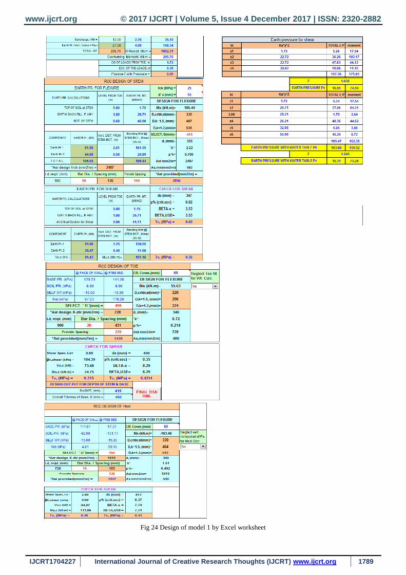
5.3 Design by Excel workshee
www.ijcrt.org © 2017 IJCRT | Volume 5, Issue 4 December 2017 | ISSN: 2320-2882
IJCRT1704227 International Journal of Creative Research Thoughts (IJCRT) www.ijcrt.org 1789
Fig 24 Design of model 1 by Excel worksheet
www.ijcrt.org © 2017 IJCRT | Volume 5, Issue 4 December 2017 | ISSN: 2320-2882
IJCRT1704227 International Journal of Creative Research Thoughts (IJCRT) www.ijcrt.org 1790
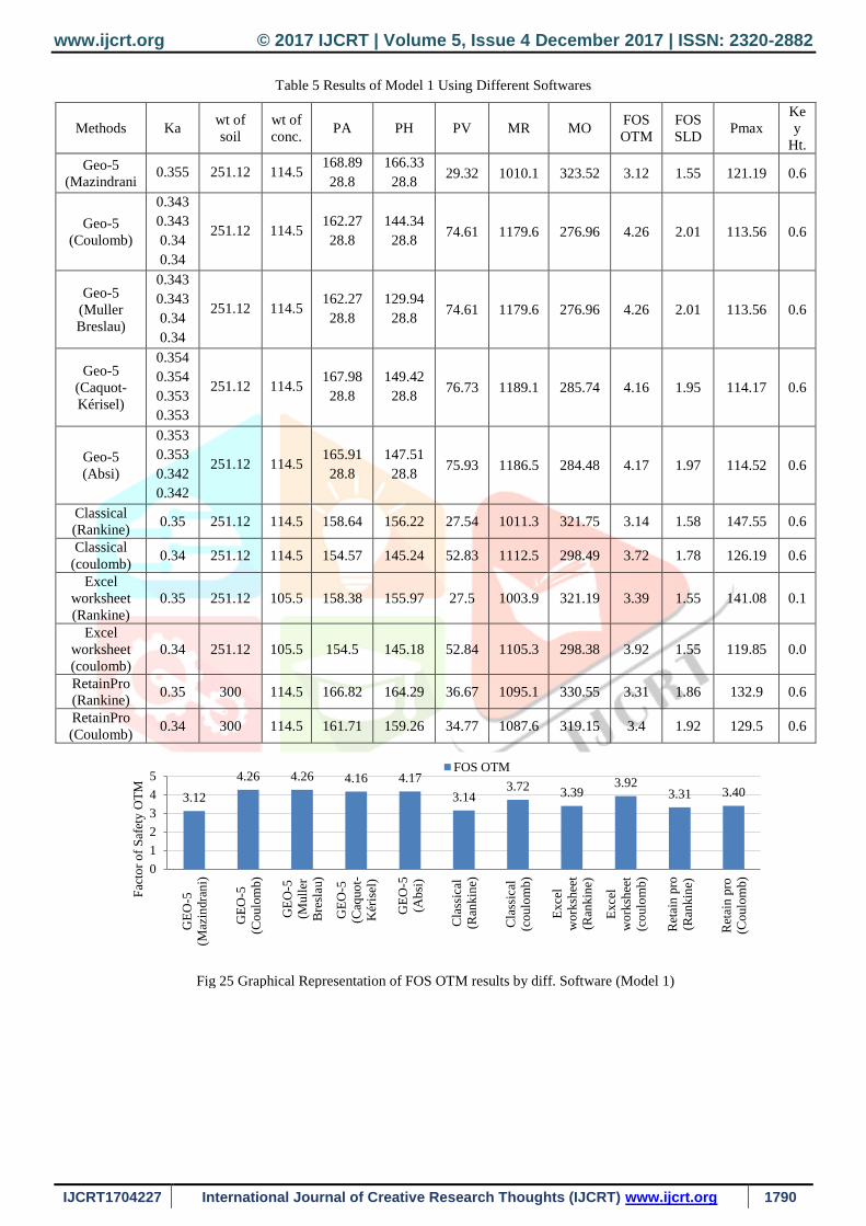
Table 5 Results of Model 1 Using Different Softwares
Methods Ka wt of
soil
wt of
conc. PA PH PV MR MO
FOS
OTM
FOS
SLD Pmax
Ke
y
Ht.
Geo-5
(Mazindrani 0.355 251.12 114.5
168.89
28.8
166.33
28.8 29.32 1010.1 323.52 3.12 1.55 121.19 0.6
Geo-5
(Coulomb)
0.343
0.343
0.34
0.34
251.12 114.5 162.27
28.8
144.34
28.8 74.61 1179.6 276.96 4.26 2.01 113.56 0.6
Geo-5
(Muller
Breslau)
0.343
0.343
0.34
0.34
251.12 114.5 162.27
28.8
129.94
28.8 74.61 1179.6 276.96 4.26 2.01 113.56 0.6
Geo-5
(Caquot-
Kérisel)
0.354
0.354
0.353
0.353
251.12 114.5 167.98
28.8
149.42
28.8 76.73 1189.1 285.74 4.16 1.95 114.17 0.6
Geo-5
(Absi)
0.353
0.353
0.342
0.342
251.12 114.5 165.91
28.8
147.51
28.8 75.93 1186.5 284.48 4.17 1.97 114.52 0.6
Classical
(Rankine) 0.35 251.12 114.5 158.64 156.22 27.54 1011.3 321.75 3.14 1.58 147.55 0.6
Classical
(coulomb) 0.34 251.12 114.5 154.57 145.24 52.83 1112.5 298.49 3.72 1.78 126.19 0.6
Excel
worksheet
(Rankine)
0.35 251.12 105.5 158.38 155.97 27.5 1003.9 321.19 3.39 1.55 141.08 0.1
Excel
worksheet
(coulomb)
0.34 251.12 105.5 154.5 145.18 52.84 1105.3 298.38 3.92 1.55 119.85 0.0
RetainPro
(Rankine) 0.35 300 114.5 166.82 164.29 36.67 1095.1 330.55 3.31 1.86 132.9 0.6
RetainPro
(Coulomb) 0.34 300 114.5 161.71 159.26 34.77 1087.6 319.15 3.4 1.92 129.5 0.6
Fig 25 Graphical Representation of FOS OTM results by diff. Software (Model 1)
3.12
4.26 4.26 4.16 4.17
3.143.72
3.393.92
3.31 3.40
0
1
2
3
4
5
GE
O-5
(Maz
indra
ni)
GE
O-5
(Co
ulo
mb)
GE
O-5
(Mull
er
Bre
slau
)
GE
O-5
(Caq
uo
t-
Kér
isel
)
GE
O-5
(Ab
si)
Cla
ssic
al
(Ran
kin
e)
Cla
ssic
al
(co
ulo
mb)
Exce
l
wo
rksh
eet
(Ran
kin
e)
Exce
l
wo
rksh
eet
(co
ulo
mb)
Ret
ain
pro
(Ran
kin
e)
Ret
ain
pro
(Co
ulo
mb)
Fac
tor
of
Saf
ety O
TM
FOS OTM
www.ijcrt.org © 2017 IJCRT | Volume 5, Issue 4 December 2017 | ISSN: 2320-2882
IJCRT1704227 International Journal of Creative Research Thoughts (IJCRT) www.ijcrt.org 1791
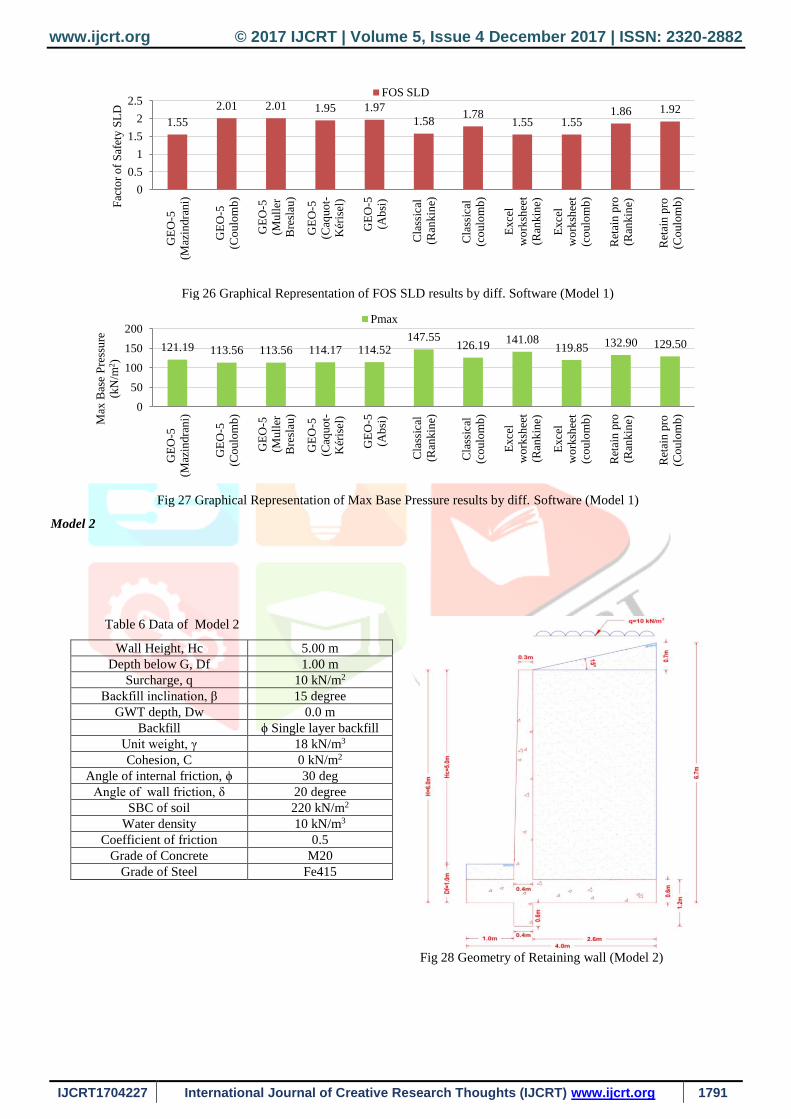
Fig 26 Graphical Representation of FOS SLD results by diff. Software (Model 1)
Fig 27 Graphical Representation of Max Base Pressure results by diff. Software (Model 1)
Model 2
Table 6 Data of Model 2
Wall Height, Hc 5.00 m
Depth below G, Df 1.00 m
Surcharge, q 10 kN/m2
Backfill inclination, β 15 degree
GWT depth, Dw 0.0 m
Backfill ϕ Single layer backfill
Unit weight, γ 18 kN/m3
Cohesion, C 0 kN/m2
Angle of internal friction, ϕ 30 deg
Angle of wall friction, δ 20 degree
SBC of soil 220 kN/m2
Water density 10 kN/m3
Coefficient of friction 0.5
Grade of Concrete M20
Grade of Steel Fe415
Fig 28 Geometry of Retaining wall (Model 2)
1.55
2.01 2.01 1.95 1.97
1.581.78
1.55 1.551.86 1.92
0
0.5
1
1.5
2
2.5
GE
O-5
(Maz
indra
ni)
GE
O-5
(Co
ulo
mb)
GE
O-5
(Mull
er
Bre
slau
)
GE
O-5
(Caq
uo
t-
Kér
isel
)
GE
O-5
(Ab
si)
Cla
ssic
al
(Ran
kin
e)
Cla
ssic
al
(co
ulo
mb)
Exce
l
wo
rksh
eet
(Ran
kin
e)
Exce
l
wo
rksh
eet
(co
ulo
mb)
Ret
ain
pro
(Ran
kin
e)
Ret
ain
pro
(Co
ulo
mb)
Fac
tor
of
Saf
ety S
LD
FOS SLD
121.19 113.56 113.56 114.17 114.52147.55
126.19141.08
119.85 132.90 129.50
0
50
100
150
200
GE
O-5
(Maz
indra
ni)
GE
O-5
(Co
ulo
mb)
GE
O-5
(Mull
er
Bre
slau
)
GE
O-5
(Caq
uo
t-
Kér
isel
)
GE
O-5
(Ab
si)
Cla
ssic
al
(Ran
kin
e)
Cla
ssic
al
(co
ulo
mb)
Exce
l
wo
rksh
eet
(Ran
kin
e)
Exce
l
wo
rksh
eet
(co
ulo
mb)
Ret
ain
pro
(Ran
kin
e)
Ret
ain
pro
(Co
ulo
mb)
Max
Bas
e P
ress
ure
(kN
/m2)
Pmax
www.ijcrt.org © 2017 IJCRT | Volume 5, Issue 4 December 2017 | ISSN: 2320-2882
IJCRT1704227 International Journal of Creative Research Thoughts (IJCRT) www.ijcrt.org 1792
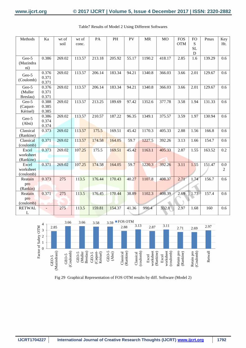
Table7 Results of Model 2 Using Different Softwares
Fig 29 Graphical Representation of FOS OTM results by diff. Software (Model 2)
Methods Ka wt of
soil
wt of
conc.
PA PH PV MR MO FOS
OTM
FO
S
SL
D
Pmax Key
Ht.
Geo-5
(Mazindra
ni)
0.386 269.02 113.57 213.18 205.92 55.17 1190.2 418.17 2.85 1.6 139.29 0.6
Geo-5
(Coulomb)
0.376
0.371
0.371
269.02 113.57 206.14 183.34 94.21 1340.8 366.03 3.66 2.01 129.67 0.6
Geo-5
(Muller
Breslau)
0.376
0.371
0.371
269.02 113.57 206.14 183.34 94.21 1340.8 366.03 3.66 2.01 129.67 0.6
Geo-5
(Caquot-
Kérisel)
0.388
0.385
0.385
269.02 113.57 213.25 189.69 97.42 1352.6 377.78 3.58 1.94 131.33 0.6
Geo-5
(Absi)
0.386
0.374
0.374
269.02 113.57 210.57 187.22 96.35 1349.1 375.57 3.59 1.97 130.94 0.6
Classical
(Rankine)
0.373 269.02 113.57 175.5 169.51 45.42 1170.3 405.33 2.88 1.56 166.8 0.6
Classical
(coulomb)
0.371 269.02 113.57 174.58 164.05 59.7 1227.5 392.26 3.13 1.66 154.7 0.6
Excel
worksheet
(Rankine)
0.373 269.02 107.25 175.5 169.51 45.42 1163.1 405.33 2.87 1.55 163.52 0.2
Excel
worksheet
(coulomb)
0.371 269.02 107.25 174.58 164.05 59.7 1220.3 392.26 3.11 1.55 151.47 0.0
2
Reatain
pro
(Rankin)
0.373 275 113.5 176.44 170.43 40.27 1107.8 408.37 2.71 1.74 156.7 0.6
Reatain
pro
(coulomb)
0.371 275 113.5 176.45 170.44 38.89 1102.3 408.39 2.69 1.73 157.4 0.6
RETWAL
L
- 275 113.5 159.81 154.37 41.36 990.4 332.8 2.97 1.68 160 0.6
2.85
3.66 3.66 3.58 3.59
2.88 3.13 2.87 3.112.71 2.69
2.97
0
1
2
3
4
GE
O-5
(Maz
indra
ni)
GE
O-5
(Co
ulo
mb)
GE
O-5
(Mull
er
Bre
slau
)
GE
O-5
(Caq
uo
t-
Kér
isel
)
GE
O-5
(Ab
si)
Cla
ssic
al
(Ran
kin
e)
Cla
ssic
al
(co
ulo
mb)
Exce
l
wo
rksh
eet
(Ran
kin
e)
Exce
l
wo
rksh
eet
(co
ulo
mb)
Ret
ain
pro
(Ran
kin
e)
Ret
ain
pro
(Coulo
mb)
Ret
wal
l
Fac
tor
of
Saf
ety O
TM
FOS OTM

www.ijcrt.org © 2017 IJCRT | Volume 5, Issue 4 December 2017 | ISSN: 2320-2882
IJCRT1704227 International Journal of Creative Research Thoughts (IJCRT) www.ijcrt.org 1793
Fig 30 Graphical Representation of FOS SLD results by diff. Software (Model 2)
Fig 31 Graphical Representation of Max Base Pressure results by diff. Soft (Model 2)
VI. RESULT AND DISCUSSION
For Model 1 result among all earth pressure theories of Geo-5, Coulomb’s and Muller Breslau theory gives higher FOS
for overturning moment is 4.26 1.55 and Mazindrani theory gives lesser FOS for sliding 1.55 1.55. Among all softwares and
their respective earth pressure theories, the most conservative maximum base pressure is 113.56 kN/m2 which is obtained by
Geo-5 software using Coulomb and Muller Breslau’s earth pressure theory. For model 2 result among all earth pressure theories
of Geo-5, Coulomb’s and Muller Breslau theory gives higher FOS for overturning moment is 3.66 1.55 and Mazindrani theory
gives lesser FOS for sliding 1.6 1.55. Among all softwares and their respective earth pressure theories, the most conservative
maximum base pressure is 129.67 kN/m2 which is obtained by Geo-5 software using Coulomb and Muller Breslau’s earth
pressure theory. So by using Mazindrani earth pressure theory the results obtained are as satisfactory as classical earth pressure
theories.
REFERENCES
[1] Kerisel, Absi: Active and passive Earth pressure tables, 3rd ed., Balkema, 1990 ISBN90
[2] Bowles, J.E. (1977) Foundation Analysis and Design, McGraw-Hill, New York.
[3] Venanzio R.Greco,Stability of retaining walls against overturning. Journal of Geotechnical and Geoenvironmental
engineering (Aug. 1997).p.p. 778-780
[4] Mazindrani Z.H., Ganjali M H.1997. Lateral earth pressure problem of cohesieve backfill with inclined surface. Journal
of geotechnical and Geo-Environmental engineering. ASCE,123(2) :110-112
[5] Arnold Verruijit: Soil mechanics, Delft University of Technology, 2001, 2006. http://geo.verruijt.net/
[6] Reinforced concrete Vol 1 by Dr. H J Shah. (Elementry Reinforced Concrete)
[7] Soil Mechanics in Engineering Practice, John Wiley And Sons, Inc, New York, Terzaghi, K. And Ralph.B.Peck (1967)
[8] Soil Mechanics and foundation engineering by A S Rao and Gopal Ranjan.
[9] Soil Mechanics and foundation engineering by V N S Murthy.
[10] Soil Mechanics and foundation engineering by Braja M Das.
[11] Shenbaga R Kaniraj (1988) Design aids in soil mechanics and foundation Engineering, Tata McGraw-Hill, Publishing
Company Limited, New Delhi.
1.602.01 2.01 1.94 1.97
1.56 1.66 1.55 1.551.74 1.73 1.68
0
0.5
1
1.5
2
2.5
GE
O-5
(Maz
indra
ni)
GE
O-5
(Co
ulo
mb)
GE
O-5
(Mull
er
Bre
slau
)
GE
O-5
(Caq
uo
t-
Kér
isel
)
GE
O-5
(Ab
si)
Cla
ssic
al
(Ran
kin
e)
Cla
ssic
al
(co
ulo
mb)
Exce
l
wo
rksh
eet
(Ran
kin
e)
Exce
l
wo
rksh
eet
(co
ulo
mb)
Ret
ain
pro
(Ran
kin
e)
Ret
ain
pro
(Co
ulo
mb)
Ret
wal
l
Fac
tor
of
Saf
ety S
LD
FOS SLD
139.29 129.67 129.67 131.33 130.94
166.80154.70 163.52
151.47 156.70 157.40 160.00
0
50
100
150
200
GE
O-5
(Maz
indra
ni)
GE
O-5
(Co
ulo
mb)
GE
O-5
(Mull
er B
resl
au)
GE
O-5
(Caq
uo
t-
Kér
isel
)
GE
O-5
(Ab
si)
Cla
ssic
al
(Ran
kin
e)
Cla
ssic
al
(co
ulo
mb)
Exce
l w
ork
shee
t
(Ran
kin
e)
Exce
l w
ork
shee
t
(co
ulo
mb)
Ret
ain
pro
(Ran
kin
e)
Ret
ain
pro
(Coulo
mb)
Ret
wal
l
Max
Bas
e P
ress
ure
(kN
/m2)
Pmax