
Second-Order Backward Stochastic Differential Equations and Fully ...
Upload
y-kobayashiCategory
view
215download
0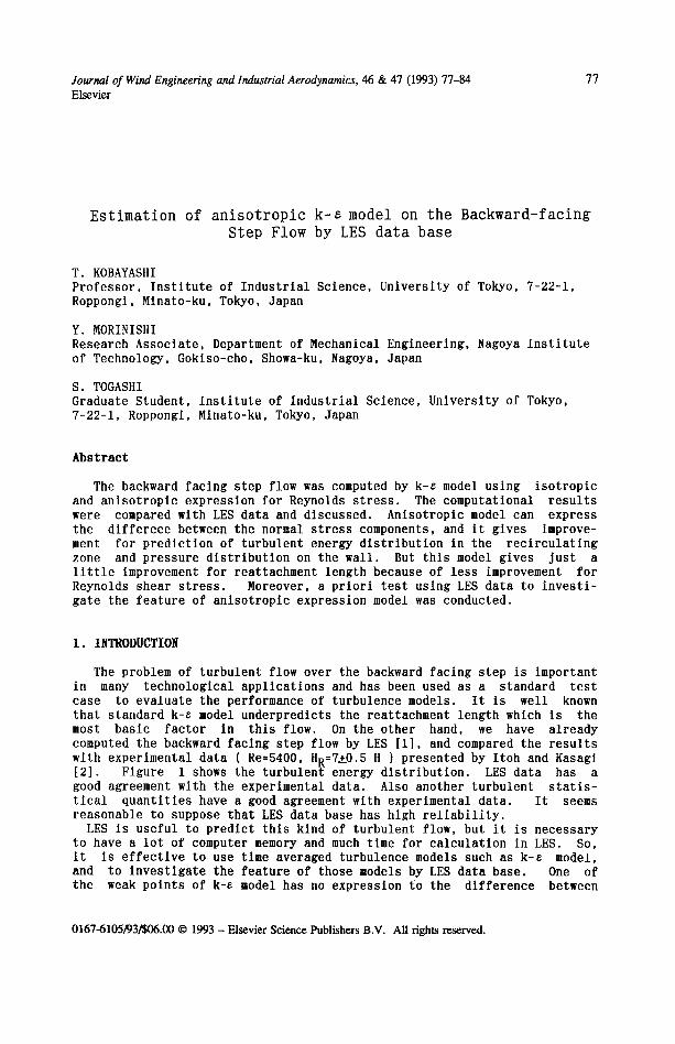
Journal of Wind Engineering and Industrial Aerodynamics, 46 & 47 (1993) 77-84 77 Elsevier
Estimation of anisotropic k-e model on the Backward-facing
Step Flow by LES data base
T. KOBAYASHI Professor, Institute of Industrial Science, University of Tokyo, 7-22-i, Roppongl, Mlnato-ku, Tokyo, Japan
Y. MORINISHI Research Associate, Department of Mechanical Engineering, Nagoya Institute of Technology, Goklso-cho, Showa-ku, Nagoya, Japan
S. TOGASHI Graduate Student, Institute of Industrial Science, University of Tokyo, 7-22-1, Roppongl, Mlnato-ku, Tokyo, Japan
Abstract
The backward f a c i n g s tep f low was computed by k-e model us ing i s o t r o p i c and a n i s o t r o p i c exp re s s ion fo r Reynolds s t r e s s . The computa t iona l r e s u l t s were compared with LES da ta and d i s cus sed . A n l s o t r o p i c model can express the d i f f e r e c e between the normal s t r e s s components, and i t g ive s improve- ment fo r p r e d i c t i o n of t u r b u l e n t energy d i s t r i b u t i o n in the r e c i r c u l a t l n g zone and p r e s s u r e d i s t r i b u t i o n on the wa l l . But t h i s model g ive s j u s t a l i t t l e improvement fo r r ea t t achment l eng th because of l e s s improvement f o r Reynolds shear s t r e s s . Moreover, a p r i o r i t e s t u s ing LES data to i n v e s t i - ga te the f e a t u r e of a n i s o t r o p l c exp re s s ion model was conducted.
I. INTRODUCTION
The problem of turbulent flow over the backward facing step is important in many technological applications and has been used as a standard test case to evaluate the performance of turbulence models. It is well known that standard k-e model underpredlcts the reattachment length which is the most basic factor in this flow. On the other hand, we have already computed the backward facing step flow by LES [1], and compared the results with experimental data ( Re=S400, HR=7±0.5 H ) presented by Itoh and Kasagi [2]. Figure i shows the turbulent energy distribution. LES data has a good agreement with the experimental data. Also another turbulent statis- tical quantities have a good agreement with experimental data. It seems reasonable to suppose that LES data base has high reliability.
LES is useful to predict this kind of turbulent flow, but it is necessary to have a lot of computer memory and much time for calculation in LES. So, it is effective to use time averaged turbulence models such as k-e model, and to investigate the feature of those models by LES data base. One of the weak points of k-e model has no expression to the difference between
0167-6105/93/$06.00 © 1993 - Elsevier Science Publishers B.V. All fights reserved.
78
2
i
0 0 i 2
0 0.04
3 4 5 6 7 XIH
Experimental da ta ( Re=S400,
HR=7±0.5 H )
LES da ta base ( Re=46000,
HR=7.1 H )
Figure 1. Turbulent energy d i s t r i b u t i o n ( k/Uc 2 )
the normal s t r e s s components. In order to improve t h i s , a n i s o t r o p i c express ion models fo r Reynolds s t r e s s have been proposed [ 3 , 4 , 5 ] . In the case of t u rbu l en t square duct flow [6], t h i s model gives the s u c c e s s f u l r e s u l t s f o r p r e d i c t i o n of the secondary flow. Spez ia le has appl ied h is o r i g i n a l model to the backward f a c i n g s tep flow [7] .
In t h i s paper, two dimensional backward f ac ing s tep flow f i e l d was com- puted by k-e model us ing i s o t r o p l c and a n l s o t r o p i c express ion for Reynolds s t r e s s . The computa t lonal r e s u l t s were compared wlth LES data , and the e f - f e c t of a n l s o t r o p i c express ion model was d i scussed .
2. TURBULENCE MODELS AND NUMERICAL METHOD
I s o t r o p i c eddy v i s c o s i t y express ion fo r Reynolds s t r e s s s t andard k-~ model is
2 a u i 0 Uj u i u j = 3- k 6 i j - - u t ( ~ - ~ + ~'-X-i )
where
used in the
(1)
k 2 ~ t=Clz ~ Clz = 0 " 0 9 " ( la)
On the o ther hand, a n i s o t r o p i c express ion model fo r Reynolds s t r e s s has been proposed us ing a s t a t i s t i c a l theory [3] . An i so t rop ic express ion fo r Reynolds s t r e s s is
2 OU i OUj
u i u j = ~- R 6 i j - ~ t ( ~-~-xj + ~-xi ) +
where a U i OUj 1
S l i j - Ox j Ox i' S2i j= -2-
k 3 1 _ (2) - - : , - - _ 6ii) t ~=lCm (Smij 3 Smaa
a u n a u j a u n a u i ( aX-n + a x j a x . ) ' (2a)
a u n a u n s 3 i j - a x i 8 x j , c 1 = 0 . 6 3 , c 2 = - 3 . 6 7 , c 3 = - 0 . 0 7 . (2b)
Three cons tan t s C1, C2, C3 have a l ready been opt imized us ing t u rbu l en t
79
square duct flow [6] and t u r b u l e n t channel flow [8] as shown in Eq . (2b) . The govern ing equa t ions are p resen ted with the f o l l ow i ng E q s . ( 3 ) - ( 7 ) :
@U i --0 (3)
a x i
(4)
a ( U j k ) a P t o k - a . j ( ) (5)
where
(Ujs) 0 ~t 88 _ _ _ _ ~--~-j)+ ~- (C~IG-Ce28) axj axj ( a (6)
a k = l ' O ' a$ =1"3" C ~ 1 - - 1 " 4 4 ' C s 2 = 1 " 9 2 (7)
The computa t iona l flow f i e l d i s a channel with a backward f a c i n g s tep having the r a t i o 1 .5 . The Reynolds number based on the s tep he lgh t H and main flow Uo l s 46000. The i n l e t and o u t l e n t of the computa t iona l r eg ion are l oca t ed a t 4H upstream and 30H downstream from the s t ep , r e s p e c t i v e l y . The computa t iona l r eg ion i s d l s c r e t l z e d by 230 x 50 non-uni form numer ica l g r id s having s taggered system. Both the l s o t r o p i c (Eq. (1)) and a n i s o t r o p i c (Eq. (2) ) expres s ion models for Reynolds s t r e s s are used. In order to e s t l - mate the h igher order terms in a n l s o t r o p i c express ion model, QUICK scheme [9] i s app l i ed to the convec t ive terms. At the i n l e t of the channe l , we used the same va lues as LES data which i s f u l l y developed t u r b u l e n t flow. The f i r s t d e r i v a t i v e s in the streamwlse d i r e c t i o n are se t zero a t the ou t - l e t . Wall f u n c t i o n [10] i s employed to p re sc lbe the boundary c o n d i t i o n s a long the w a l l s . The c o n t r o l volume approach i s adopted to so lve the govern ing equa t ions in the f i n i t e d i f e r ence scheme. The p re s su re and mean v e l o c i t y f i e l d s are coupled with the SIMPLE a lgor i thm [11].
3. RESULTS ~ DISCUSSIONS
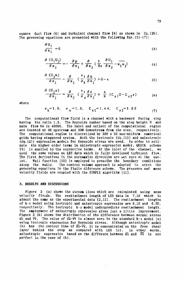
Figure 2 (a) shows the stream l i n e s which are c a l c u l a t e d u s i n g mean v e l o c i t y f i e l d s . The rea t tachment l eng th of LES da ta in 7.1H which i s almost the same as the exper imenta l da ta [2 ,12] . The rea t t achment l eng ths of k-~ model u s i n g l s o t r o p l c and a n l s o t r o p l c express ion are 6.1H and 6.3H, r e s p e c t i v e l y . The l s o t r o p i c k-~ model u n d e r p r e d i c t s r ea t t achment l e n g t h . The employment of a n l s o t r o p l c express ion g ives j u s t a l i t t l e improvement. F igure 2 (b) shows the d i s t r i b u t i o n of the d i f f e r e n c e between normal s t r e s s d-u and ~ . The va lue of ~-u-~ l s almost zero in the s t andard k-e model (a) u s i n g l s o t r o p l c express ion for Reynolds s t r e s s . Although a n l s o t r o p l c model (b) has the contour l l n e of f f h - ~ , i t i s c o n c e n t r a t e d on the f r ee shear l aye r behind the s tep as compared with LES (c) . In o ther words, a n l s o t r o p l c express ion based on the d i f f e r e c e between fi-u and ~ i s not p e r f e c t in the case of (b) .
80
(a) Standard (HR=6.1 H)
(b) Anlsotropic (BR=6.3 H)
o 5 X/If
0 5 X/lt
o ~ x/H
\
0 5 X/tl
(c) LES (HR=7.1 H)
0 5 X/l{
Figure 2 (a). Stream line
o 5 kAl
(b) . D i s t r i b u t i o n of uu-vv
T2
> - - 1 '
0 0.02 ! ' .
0 2 4 6 8 I0 12 X/H Figu re 3. Reynolds shear s t r e s s p r o f i l e s
0 LES
. . . . Standard
Anisotropic
3 0 0.2
, I I I I
o , ' I ! ,, , 0 2 4 6 8 i0 1; 5 X/H
Figu re 4. Turbu len t energy p r o f i l e s
0 LES
..... Standard
hnisotropic
0 0.04
o ~. i L ' i t j ~ 0 2 4 6 B I 0 12 X/H
Figure 5. Turbulent intensity profi les
0 LES
. . . . Standa rd
Anisotropic
c~
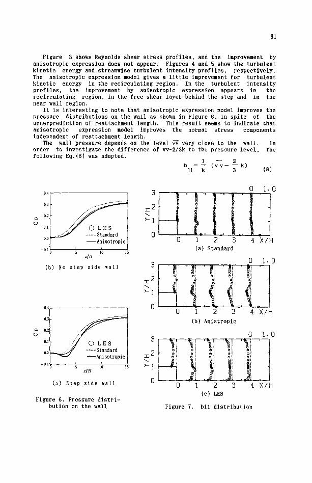
Figure 3 shows Reynolds shear stress profiles, and the improvement by anlsotropic expression does not appear. Figures 4 and 5 show the turbulent kinetic energy and streamwise turbulent intensity profiles, respectively. The anlsotropic expression model gives a little improvement for turbulent kinetic energy in the recirculating region. In the turbulent intensity profiles, the improvement by anisotropic expression appears in the reclrculating region, in the free shear layer behind the step and in the near wall region.
It is interesting to note that anisotropic expression model improves the pressure distributions on the wall as shown In Figure 6, in spite of the underprediction of reattachment length. This result seems to indicate that anlsotropic expression model improves the normal stress components independent of reattachment length.
The wall pressure depends on the level ~very close to the wall. In order to investigate the difference of ~-2/3k to the pressure level, the following Eq.(8) was adapted.
1 -- 2 b = -- ( v v - - -- k)
1 1 k 3 (8)
e~ ¢D
0.4
0.4
0.3
0.2
0.1
0.0
- 0 . 1
.,.°.......**-'*" ........................
~Anisotropic I
5 10 15
(b) No s t ep s ide wal l
0.3
0.2
0.1
0.0
- 0 . I
81
t
I0 15 HH (a) Step s i d e wal l
F igure 6. P ressure d i s t r i - b u t i o n on the wal l
~-2
>-1
0 1.0
!iiii o 1 2 3 4 X/H
(a) Standard
>-1
0
=2 >-]
0 i 0
,
I I o .
0 1 2 3 4 X/H
(b) A n l s t r o p l c
0 1.0
y oi i oi o
0 1 2 3 4 X/H
(c) LES
Figure 7. b l l d i s t r i b u t i o n
82
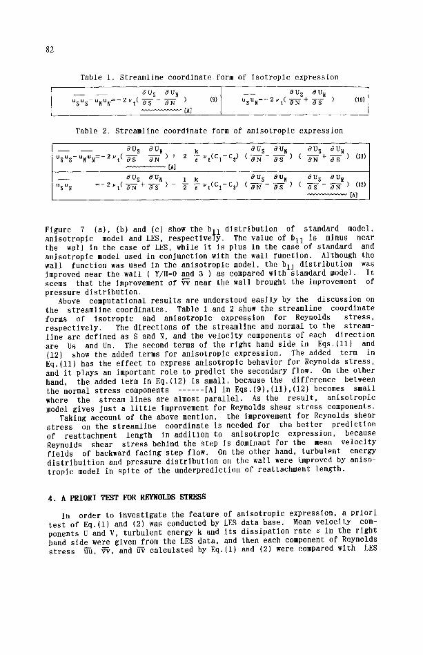
Table 1. S t r eaml ine c o o r d i n a t e form of i s o t r o p i c exp re s s ion
~U S a u N UsUs-UNUN=- 2 Yt ( a s ON ) (9)
[A]
a U S a u~ u s u N = - 2 v t ( ~ - - ~ - t - ~-~- ) (10)
Table 2. S t r eaml ine c o o r d i n a t e form of a n l s o t r o p i c exp re s s ion
- aUs nun k aUs nUN aUs nUN umu$-uNuN=-2Yt( aS - ~ - ) + 2 T Yt(Cl-C3 ) ( 8N aS ) ( @N+ a-s- ) (11)
[̂ ]
_ _ a u s a u ~ 1 ~ a u s a u N a u s a u g u s u N = - 2 ~ t ( a - N +-~-S-) - T z- yt (c1-c$ ) ( aN OS ) ( a s 8N ) (12)
F igure 7 (a ) , (b) and (c) show the b l l d i s t r i b u t i o n of s t andard model, a n i s o t r o p i c model and LES, r e s p e c t i v e l y . The va lue of b l l i s minus near the wal l in the case of LES, whl le i t i s p lus in the case of s t andard and a n l s o t r o p i c model used in c o n j u n c t i o n with the wal l f u n c t i o n . Although the wal l f u n c t i o n was used In the a n i s o t r o p l c model, the b l l d i s t r i b u t i o n was improved near the wal l ( Y/H=0 and 3 ) as compared with s tandard model. I t seems t h a t the improvement of ~ near the wal l brought the improvement of p r e s s u r e d i s t r i b u t i o n .
Above computa t iona l r e s u l t s a re unders tood e a s i l y by the d i s c u s s i o n on the s t r e a m l i n e c o o r d i n a t e s . Table 1 and 2 show the s t r e a m l i n e c o o r d i n a t e forms of l s o t r o p l c and a n l s o t r o p l c e x p r e s s i o n fo r Reynolds s t r e s s , r e s p e c t i v e l y . The d i r e c t i o n s of the s t r e a m l i n e and normal to the s t ream- l i n e are d e f i n e d as S and N, and the v e l o c i t y components of each d i r e c t i o n are Us and Un. The second terms of the r i g h t hand s ide in E q s . ( l l ) and (12) show the added terms fo r a n i s o t r o p i c e x p r e s s i o n , The added term in E q . ( l l ) has the e f f e c t to express a n i s o t r o p i c behav io r fo r Reynolds s t r e s s , and i t p lays an impor tant r o l e to p r e d i c t the secondary f low. On the o the r hand, the added term in Eq.(12) i s smal l , because the d i f f e r e n c e between the normal s t r e s s components . . . . . . [A] in E q s . ( 9 ) , ( l l ) , ( 1 2 } becomes smal l where the s tream l i n e s are almost p a r a l l e l . As the r e s u l t , a n i s o t r o p i c model g ive s J u s t a l i t t l e improvement fo r Reynolds shear s t r e s s components.
Taking account of the above mention, the improvement fo r Reynolds shear s t r e s s on the s t r e a m l i n e c o o r d i n a t e i s needed f o r the b e t t e r p r e d i c t i o n of r ea t t achmen t l eng th in a d d i t i o n to a n l s o t r o p i c e x p r e s s i o n , because Reynolds shear s t r e s s behind the s tep i s dominant fo r the mean v e l o c i t y f l e l d s of backward f a c i n g s tep f low. On the o the r hand, t u r b u l e n t energy d i s t r i b u i t i o n and p r e s s u r e d i s t r i b u t i o n on the wal l were improved by a n i s o - t r o p i c model in s p i t e of the u n d e r p r e d i c t i o n of r ea t t achment l eng th .
4 . A PRIORI TEST FOR REYNOLDS STRESS
In o rder to i n v e s t i g a t e the f e a t u r e of a n i s o t r o p i c e x p r e s s i o n , a p r i o r i t e s t of Eq.(1) and (2) was conducted by LES data base . Mean v e l o c i t y com- ponents U and V, t u r b u l e n t energy k and i t s d i s s i p a t i o n r a t e e in the r i g h t hand s ide were g iven from the LES da ta , and then each component of Reynolds s t r e s s uu, vv, and ~ c a l c u l a t e d by Eq.(1) and (2) were compared with LES
83
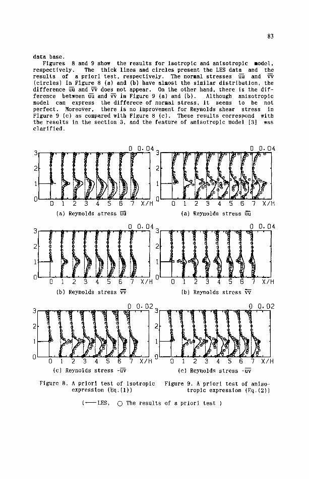
data base. Figures 8 and 9 show the results for isotroplc and anlsotropic model,
respectively. The thick lines and circles present the LES data and the results of a priori test, respectively. The normal stresses u-d and (circles) in Figure 8 (a) and (b) have almost the similar distribution, the difference ~fi and W does not appear. On the other hand, there is the dif- ference between fffi and ~ in Figure 9 (a) and (b). Although anisotropic model can express the dlfferece of normal stress, it seems to be not perfect. Moreover, there is no improvement for Reynolds shear stress in Figure 9 (c) as compared with Figure 8 (c). These results correspond with the results in the section 3, and the feature of anisotroplc model [3] was clarifled.
0 0 . 0 4
o , 0 1 2 3 4 5 6 -7 X/H
(a) Reynolds s t r e s s u--t]
0 0 . 0 4
r,tt.rt' t 0 0 1 2 3 ,1 5 6 7 X/H
(a) Reynolds stress u-d
3 0 0 . 0 4 3
1 • I '
, i I . 0
0 1 2 3 4 5 6 ? × / H
(b) Reynolds s t r e s s ~
0 0.04
, . ~ . ° i ° .
0 1 2 3 4 5 6 ? X/H
(b) Reynolds s t r e s s ~
0 0.02
2
1
0 0 0 1 2 3 4 5 6 -7 X/H
(c) Reynolds s t r e s s -~-~
0 0.02 . . . .
0 1 2 3 4 5 6 -/ X/H
(c) Reynolds s t r e s s -u-v
Figure 8. A priori test of isotroplc Figure 9. A priori test of anlso- expression (Eq.(1)) tropic expression (Eq.(2))
( LES, 0 The r e s u l t s of a p r i o r i t e s t )
84
5. FINAL ~ S
The backward f a c i n g s tep flow was computed by k-~ model u s i ng i s o t r o p i c and a n i s o t r o p l c express ion [3] for Reynolds s t r e s s . The computa t ional re - s u l t s were compared with LES data and d i scussed .
h n i s o t r o p i c model can express the d i f f e r e n c e between normal s t r e s s com- ponen ts , and give the improvement for t u r b u l e n t energy d i s t r i b u t i o n and p re s su re d i s t r i b u t i o n on the wal l . On the o ther hand, t h i s model g ives j u s t a l i t t l e improvement for rea t tachment l eng th because of l e s s improve- ment for Reynolds shear s t r e s s .
In order to get more improvement, we are t r y i n g to c a l c u l a t e by a l g e b r a i c s t r e s s model, and a l so i n v e s t i g a t e the e f f e c t of d i f f u s i o n term in t u r b u l e n t energy k equa t ion .
REFERENCES
1 Y. MorJnishi and T. Kobayashl, Eng inee r ing Turbulence Model l ing and Experelments , E l s e v i e r , (1990) 245.
2 N. I t oh , and N. gasagi , J. Flow v i s u a l i z a t i o n s o c i e t y of Japan 34, (1989) 245.
3 A. Yoshlzawa, Phys. F lu id s 27, (1984) 279. 4 H. K. Myong, and N. gasagi , JSME, B, 54-507, (1988) 3003. 5 C. G. Spez l a l e , J. F lu id Mech., 178, (1987) 459. 6 S. N i sh i j lma , JSME, B, 55-512, (1989) 991. 7 C. G. Spez ia l e , and T. Ngo, I n t . J. Eng. Sci , 26, (1988) 1099. 8 S. N l sh l j ima , and h. Yoshizawa, hIhh J. 25, (1987) 414. 9 B. e. Leonard, Comp. Meth. Appl. Mech. and Eng. 19, (1979) 58.
10 B. E. Launder, and D. B. Spald ing , Comp. Meth. hppl . Mech. and Eng. 3, (1976) 269.
11 S. V. Pa tankar , Numerical Heat T rans fe r and F lu id Flow, Hemisphere, (1989) 113.
12 J. Kim, S. J. Kl ine , and J. P. Johnston, Tech. Rep. MD-37, Thermosei- ences Div. , Rep. of Mech. Eng., S tanford U n i v e r s i t y (1978).


![Exercises for Chapter 3 3.1 Solution for Chapter 3 3.1 [Fermions and bosons; the ultimate elementary problem] There is a system with only three states with energies 0, ϵ and ϵ (ϵ](https://static.fdocument.org/doc/165x107/5acb65997f8b9a63398baa06/exercises-for-chapter-3-31-for-chapter-3-31-fermions-and-bosons-the-ultimate.jpg)