Epipolar Time-of-Flight Imaging - cs.toronto.edukyros/pubs/17.siggraph.epitof.pdfEpipolar...
8
Epipolar Time-of-Flight Imaging SUPREETH ACHAR, Carnegie Mellon University JOSEPH R. BARTELS, Carnegie Mellon University WILLIAM L. ‘RED’ WHITTAKER, Carnegie Mellon University KIRIAKOS N. KUTULAKOS, University of Toronto SRINIVASA G. NARASIMHAN, Carnegie Mellon University Epipolar ToF Regular ToF Fig. 1. We demonstrate, for the first time: (a) Live 3D CW-ToF imaging in sunlight (70 klx) with 15 m range (people walking on stairs, phase wraps around on distant building). (b) Elimination of most global light transport during image capture (glossy reflection from projection screen onto a conference table). (c) Capture virtually no interference from other ToF devices operating at the same frequency (observe errors on the wall and chair with regular ToF). (d) Live un-distortion of depth maps even when the camera is shaken violently during scene exposure (observe hard to remove ghosting errors in regular ToF) Consumer time-of-ight depth cameras like Kinect and PMD are cheap, compact and produce video-rate depth maps in short-range applications. In this paper we apply energy-ecient epipolar imaging to the ToF domain to signicantly expand the versatility of these sensors: we demonstrate live 3D imaging at over 15 m range outdoors in bright sunlight; robustness to global transport eects such as specular and diuse inter-reections—the rst live demonstration for this ToF technology; interference-free 3D imaging in the presence of many ToF sensors, even when they are all operating at the same optical wavelength and modulation frequency; and blur-free, distortion-free 3D video in the presence of severe camera shake. We believe these achievements can make such cheap ToF devices broadly applicable in consumer and robotics domains. CCS Concepts: •Computing methodologies → 3D imaging; Active vi- sion; Epipolar geometry; Computational photography; Additional Key Words and Phrases: Time-of-ight, depth cameras Permission to make digital or hard copies of all or part of this work for personal or classroom use is granted without fee provided that copies are not made or distributed for prot or commercial advantage and that copies bear this notice and the full citation on the rst page. Copyrights for components of this work owned by others than ACM must be honored. Abstracting with credit is permied. To copy otherwise, or republish, to post on servers or to redistribute to lists, requires prior specic permission and/or a fee. Request permissions from [email protected]. © 2017 ACM. 0730-0301/2017/7-ART37 $15.00 DOI: hp://dx.doi.org/10.1145/3072959.3073686 ACM Reference format: Supreeth Achar, Joseph R. Bartels, William L. ‘Red’ Whiaker, Kiriakos N. Kutulakos, and Srinivasa G. Narasimhan. 2017. Epipolar Time-of-Flight Imaging. ACM Trans. Graph. 36, 4, Article 37 (July 2017), 8 pages. DOI: hp://dx.doi.org/10.1145/3072959.3073686 1 INTRODUCTION Time-of-ight (ToF) depth sensors have become the technology of choice in diverse applications today, from automotive and avia- tion to robotics, gaming and consumer electronics. ese sensors come in two general avors: LIDAR-based systems that rely on extremely brief pulses of light to sense depth, and continuous-wave systems that emit a modulated light signal over much longer dura- tion. e former can acquire centimeter-accurate depth maps up to a kilometer away in broad daylight but they have low measure- ment rates and their cost per pixel is orders of magnitude higher than laer—whose range, outdoor operation and robustness are extremely limited. Since low cost, large-scale production and high measurement rate oen trump other considerations, continuous- wave ToF (CW-ToF) sensors continue to dominate the consumer electronics and low-end robotics space despite their shortcomings. ACM Transactions on Graphics, Vol. 36, No. 4, Article 37. Publication date: July 2017.
Transcript of Epipolar Time-of-Flight Imaging - cs.toronto.edukyros/pubs/17.siggraph.epitof.pdfEpipolar...
Epipolar Time-of-Flight Imaging
SUPREETH ACHAR, Carnegie Mellon UniversityJOSEPH R. BARTELS, Carnegie Mellon UniversityWILLIAM L. ‘RED’ WHITTAKER, Carnegie Mellon UniversityKIRIAKOS N. KUTULAKOS, University of TorontoSRINIVASA G. NARASIMHAN, Carnegie Mellon University
Epip
olar
ToF
Regu
larT
oF
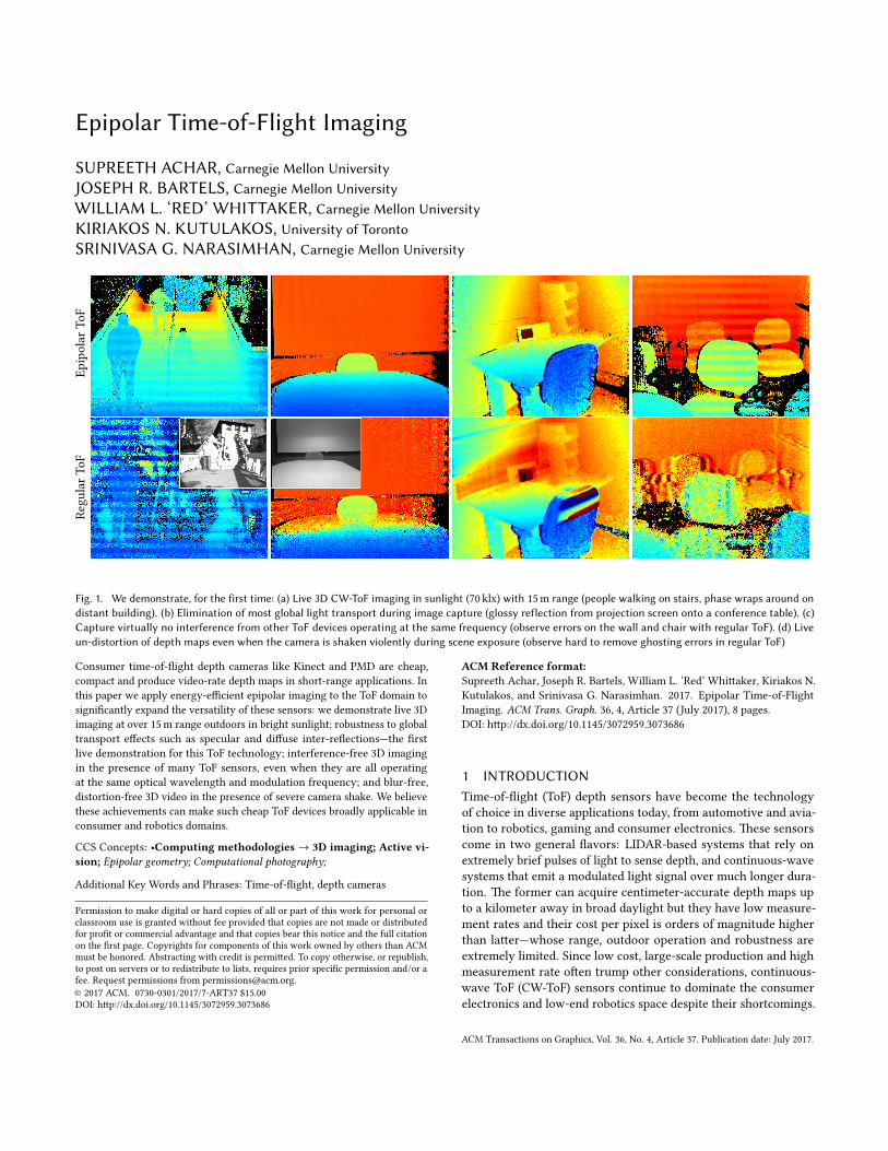
Fig. 1. We demonstrate, for the first time: (a) Live 3D CW-ToF imaging in sunlight (70 klx) with 15 m range (people walking on stairs, phase wraps around ondistant building). (b) Elimination of most global light transport during image capture (glossy reflection from projection screen onto a conference table). (c)Capture virtually no interference from other ToF devices operating at the same frequency (observe errors on the wall and chair with regular ToF). (d) Liveun-distortion of depth maps even when the camera is shaken violently during scene exposure (observe hard to remove ghosting errors in regular ToF)
Consumer time-of-�ight depth cameras like Kinect and PMD are cheap,compact and produce video-rate depth maps in short-range applications. Inthis paper we apply energy-e�cient epipolar imaging to the ToF domain tosigni�cantly expand the versatility of these sensors: we demonstrate live 3Dimaging at over 15 m range outdoors in bright sunlight; robustness to globaltransport e�ects such as specular and di�use inter-re�ections—the �rstlive demonstration for this ToF technology; interference-free 3D imagingin the presence of many ToF sensors, even when they are all operatingat the same optical wavelength and modulation frequency; and blur-free,distortion-free 3D video in the presence of severe camera shake. We believethese achievements can make such cheap ToF devices broadly applicable inconsumer and robotics domains.
CCS Concepts: •Computing methodologies→ 3D imaging; Active vi-sion; Epipolar geometry; Computational photography;
Additional Key Words and Phrases: Time-of-�ight, depth cameras
Permission to make digital or hard copies of all or part of this work for personal orclassroom use is granted without fee provided that copies are not made or distributedfor pro�t or commercial advantage and that copies bear this notice and the full citationon the �rst page. Copyrights for components of this work owned by others than ACMmust be honored. Abstracting with credit is permi�ed. To copy otherwise, or republish,to post on servers or to redistribute to lists, requires prior speci�c permission and/or afee. Request permissions from [email protected].© 2017 ACM. 0730-0301/2017/7-ART37 $15.00DOI: h�p://dx.doi.org/10.1145/3072959.3073686
ACM Reference format:Supreeth Achar, Joseph R. Bartels, William L. ‘Red’ Whi�aker, Kiriakos N.Kutulakos, and Srinivasa G. Narasimhan. 2017. Epipolar Time-of-FlightImaging. ACM Trans. Graph. 36, 4, Article 37 (July 2017), 8 pages.DOI: h�p://dx.doi.org/10.1145/3072959.3073686
1 INTRODUCTIONTime-of-�ight (ToF) depth sensors have become the technologyof choice in diverse applications today, from automotive and avia-tion to robotics, gaming and consumer electronics. �ese sensorscome in two general �avors: LIDAR-based systems that rely onextremely brief pulses of light to sense depth, and continuous-wavesystems that emit a modulated light signal over much longer dura-tion. �e former can acquire centimeter-accurate depth maps upto a kilometer away in broad daylight but they have low measure-ment rates and their cost per pixel is orders of magnitude higherthan la�er—whose range, outdoor operation and robustness areextremely limited. Since low cost, large-scale production and highmeasurement rate o�en trump other considerations, continuous-wave ToF (CW-ToF) sensors continue to dominate the consumerelectronics and low-end robotics space despite their shortcomings.
ACM Transactions on Graphics, Vol. 36, No. 4, Article 37. Publication date: July 2017.
37:2 • Achar, S. et al.
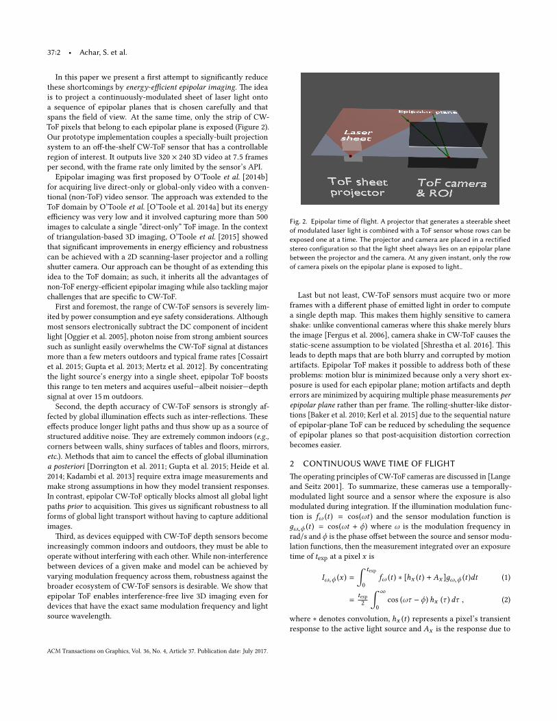
In this paper we present a �rst a�empt to signi�cantly reducethese shortcomings by energy-e�cient epipolar imaging. �e ideais to project a continuously-modulated sheet of laser light ontoa sequence of epipolar planes that is chosen carefully and thatspans the �eld of view. At the same time, only the strip of CW-ToF pixels that belong to each epipolar plane is exposed (Figure 2).Our prototype implementation couples a specially-built projectionsystem to an o�-the-shelf CW-ToF sensor that has a controllableregion of interest. It outputs live 320 × 240 3D video at 7.5 framesper second, with the frame rate only limited by the sensor’s API.
Epipolar imaging was �rst proposed by O’Toole et al. [2014b]for acquiring live direct-only or global-only video with a conven-tional (non-ToF) video sensor. �e approach was extended to theToF domain by O’Toole et al. [O’Toole et al. 2014a] but its energye�ciency was very low and it involved capturing more than 500images to calculate a single “direct-only” ToF image. In the contextof triangulation-based 3D imaging, O’Toole et al. [2015] showedthat signi�cant improvements in energy e�ciency and robustnesscan be achieved with a 2D scanning-laser projector and a rollingshu�er camera. Our approach can be thought of as extending thisidea to the ToF domain; as such, it inherits all the advantages ofnon-ToF energy-e�cient epipolar imaging while also tackling majorchallenges that are speci�c to CW-ToF.
First and foremost, the range of CW-ToF sensors is severely lim-ited by power consumption and eye safety considerations. Althoughmost sensors electronically subtract the DC component of incidentlight [Oggier et al. 2005], photon noise from strong ambient sourcessuch as sunlight easily overwhelms the CW-ToF signal at distancesmore than a few meters outdoors and typical frame rates [Cossairtet al. 2015; Gupta et al. 2013; Mertz et al. 2012]. By concentratingthe light source’s energy into a single sheet, epipolar ToF booststhis range to ten meters and acquires useful—albeit noisier—depthsignal at over 15 m outdoors.
Second, the depth accuracy of CW-ToF sensors is strongly af-fected by global illumination e�ects such as inter-re�ections. �esee�ects produce longer light paths and thus show up as a source ofstructured additive noise. �ey are extremely common indoors (e.g.,corners between walls, shiny surfaces of tables and �oors, mirrors,etc.). Methods that aim to cancel the e�ects of global illuminationa posteriori [Dorrington et al. 2011; Gupta et al. 2015; Heide et al.2014; Kadambi et al. 2013] require extra image measurements andmake strong assumptions in how they model transient responses.In contrast, epipolar CW-ToF optically blocks almost all global lightpaths prior to acquisition. �is gives us signi�cant robustness to allforms of global light transport without having to capture additionalimages.
�ird, as devices equipped with CW-ToF depth sensors becomeincreasingly common indoors and outdoors, they must be able tooperate without interfering with each other. While non-interferencebetween devices of a given make and model can be achieved byvarying modulation frequency across them, robustness against thebroader ecosystem of CW-ToF sensors is desirable. We show thatepipolar ToF enables interference-free live 3D imaging even fordevices that have the exact same modulation frequency and lightsource wavelength.
Fig. 2. Epipolar time of flight. A projector that generates a steerable sheetof modulated laser light is combined with a ToF sensor whose rows can beexposed one at a time. The projector and camera are placed in a rectifiedstereo configuration so that the light sheet always lies on an epipolar planebetween the projector and the camera. At any given instant, only the rowof camera pixels on the epipolar plane is exposed to light..
Last but not least, CW-ToF sensors must acquire two or moreframes with a di�erent phase of emi�ed light in order to computea single depth map. �is makes them highly sensitive to camerashake: unlike conventional cameras where this shake merely blursthe image [Fergus et al. 2006], camera shake in CW-ToF causes thestatic-scene assumption to be violated [Shrestha et al. 2016]. �isleads to depth maps that are both blurry and corrupted by motionartifacts. Epipolar ToF makes it possible to address both of theseproblems: motion blur is minimized because only a very short ex-posure is used for each epipolar plane; motion artifacts and deptherrors are minimized by acquiring multiple phase measurements perepipolar plane rather than per frame. �e rolling-shu�er-like distor-tions [Baker et al. 2010; Kerl et al. 2015] due to the sequential natureof epipolar-plane ToF can be reduced by scheduling the sequenceof epipolar planes so that post-acquisition distortion correctionbecomes easier.
2 CONTINUOUS WAVE TIME OF FLIGHT�e operating principles of CW-ToF cameras are discussed in [Langeand Seitz 2001]. To summarize, these cameras use a temporally-modulated light source and a sensor where the exposure is alsomodulated during integration. If the illumination modulation func-tion is fω (t ) = cos(ωt ) and the sensor modulation function isдω,ϕ (t ) = cos(ωt + ϕ) where ω is the modulation frequency inrad/s and ϕ is the phase o�set between the source and sensor modu-lation functions, then the measurement integrated over an exposuretime of texp at a pixel x is
Iω,ϕ (x ) =
∫ texp
0fω (t ) ∗ [hx (t ) +Ax ]дω,ϕ (t )dt (1)
=texp
2
∫ ∞
0cos (ωτ − ϕ) hx (τ ) dτ , (2)
where ∗ denotes convolution, hx (t ) represents a pixel’s transientresponse to the active light source and Ax is the response due to
ACM Transactions on Graphics, Vol. 36, No. 4, Article 37. Publication date: July 2017.
Epipolar Time-of-Flight Imaging • 37:3
the DC componenent of the active light source as well as otherambient sources. In practice, Iω,ϕ (x ) is measured by integratingincoming light to two di�erent storage sites (called taps) dependingon whether дω,ϕ (t ) is positive or negative and then taking thedi�erence between the stored values. �us even though Ax dropsout of the integral, ambient light still adds to the measurement shotnoise.
If there are no indirect light paths between the light source andsensor pixel x , then hx (t ) ∝ δ (t − l (x )/c ) where c is the speed oflight and l (x ) is the length of the path from the light source to thescene point corresponding to x and back to the sensor. Assumingthe scene is static, we can recover the path length l (x ) by capturinga pair of images at the same frequency but two di�erent modulationphases ϕ = 0 and ϕ = π/2:
l (x ) =c
2ω atan2(Iω, π2
(x ), Iω,0 (x )). (3)
�e pixel depth z (x ) can be computed from l (x ) using the geometriccalibration parameters of the light source and sensor.
3 EPIPOLAR TIME OF FLIGHTTo realize the geometry of Figure 2, we use a line laser source witha 1D-scanning mirror that projects a steerable light sheet onto thescene. No currently-available CW-ToF sensor provides controllableexposure coding across the 2D pixel array. Taking into accountavailable o�-the-shelf hardware, there are three possible ways torestrict exposure to pixels on a single epipolar plane: (1) use aDigital Micromirror Device (DMD) to mask all other pixels; (2) usea 1D sensor and a controllable mirror to select the epipolar plane itshould image; or (3) use a 2D sensor with a controllable region ofinterest (ROI). We chose the third option because it is much morelight-e�cient than a DMD mask and leads to a much simpler design.We make the ROI one row tall to match the requirements of epipolarToF.
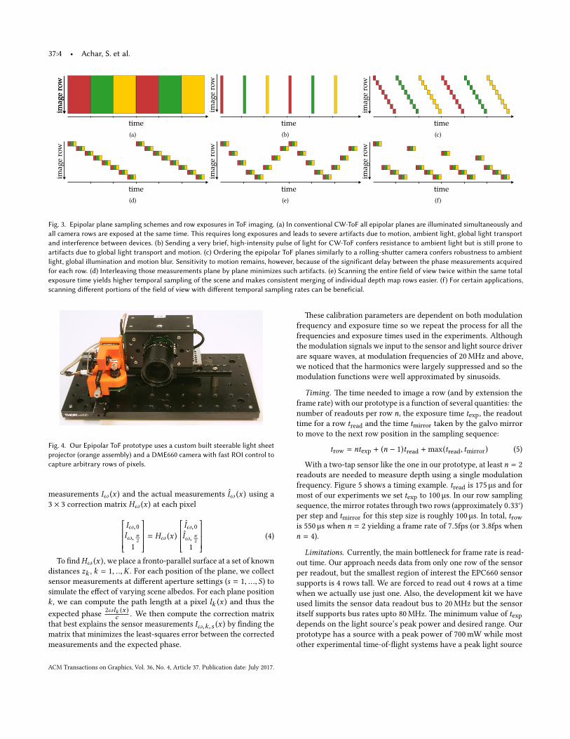
Epipolar plane sampling. As explained in Section 2, CW-ToF re-quires at least two images to recover depth. To cover an entire sceneusing epipolar ToF, the active epipolar plane must be swept acrossthe �eld of view. �is o�ers �exibility to chose the order in whichepipolar planes are sampled.
Figure 3 illustrates several such ordering schemes. For instance,the ordering scheme of Figure 3c illustrates the operation of a hy-pothetical rolling-shu�er ToF camera, where one complete imageis acquired for each modulation phase. �is scheme is undesirablebecause if the scene or camera move while acquiring these images,the recovered depth map will contain hard-to-correct errors.
A be�er ordering strategy is to loop through the set of modulationphases at one epipolar plane before imaging the next row (Figure 3d).Since each row’s exposure time is very short, all phases requiredfor a single row can be acquired quickly enough to minimize depthand motion blur artifacts due to camera/scene motion.
Under this strategy, each row is captured at a slightly di�erenttime. Although this induces a rolling-shu�er-like e�ect in the ac-quired depth map, the individual depth values will be blur- andartifact-free and can be combined into a consistent model by post-processing [Alismail et al. 2014; Kerl et al. 2015].
To make such post-processing even easier while obeying thekinematic constraints of the mirror’s actuator, we order epipolarplanes in a sawtooth pa�ern (Figure 3e). �is essentially providesfull-�eld-of-view depth maps at twice the frame rate but half thevertical resolution, making depth correction easier for fast camerashake and/or scene motions. More generally, Figure 3f shows anexample of a non-uniform sampling scheme in which epipolar planescorresponding to lower image rows are sampled more frequently.�is type of sampling could be useful on a vehicle where lowerportions of the �eld of view are usually closer and move faster,requiring acquisition at a faster sampling rate.
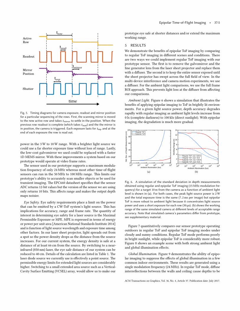
4 EPIPOLAR TOF PROTOTYPEOur prototype device for epipolar time-of-�ight imaging uses agalvomirror-based light sheet projector for illumination and a ToFsensor with an adjustable region of interest for imaging.
�e time-of-�ight sensor we use is the EPC660 (from Espros Pho-tonics) which has a resolution of 320x240 and pixels that implementambient saturation prevention. �e sensor is ��ed with a 8 mmF1.6 low distortion lens and an optical bandpass �lter (650 nm cen-ter frequency, 20 nm bandwidth). �e sensor allows the ROI to bechanged with every sensor readout and we use this feature to selectwhich row to image. We read data out of the sensor using the sensordevelopment kit (DME660) from the manufacturer.
Our line projector uses a 658 nm laser diode with a peak powerof 700 mW. Light from the diode is collimated and passed througha Powell lens that stretches the beam cross-section into a diverging,almost uniformly illuminated straight line with a 45° fanout angle.�e laser light is directed at a 1D scanning galvomirror that can berotated to de�ect the sheet. �e rotational range of the mirror givesthe projector a 40° vertical �eld of view. �e projector’s e�ectivecenter of projection moves as the mirror rotates but this e�ect canbe ignored because the distance between the fanout point and thegalvomirror is very small compared to depths in the scene.
A microcontroller is used to synchronize the sensor and lightsource. �e microcontroller communicates with the sensor over anI2C bus to set the exposure time, modulation frequency/phase andregion-of-interest row and also to trigger each capture. �e micro-controller also actuates the projector’s galvomirror. In addition, themicrocontroller can read the camera’s rotational velocity from aMEMS IMU (inertial magnetic unit) that we have a�ached to the sen-sor. A frequency generator circuit allows us to select a modulationfrequency between 1 MHz and 24 MHz in steps of 1 MHz.
We align the projector and camera side-by-side in a recti�edstereo con�guration as required for epipolar imaging. When cor-rectly aligned, the projected light sheet illuminates a single rowof pixels in the camera and this row is independent of depth. Amirror calibration is performed to determine the mapping betweengalvomirror angle and illuminated camera row.
Sensor Calibration. In practice, we observe that the measurementsread out from the sensor do not match their expected values. �ereare a number of reasons for this discrepancy, including �xed-pa�ernnoise, non-uniform pixel sensitivity, crosstalk between taps andsmall variations in the phase of the exposure modulation functionat each pixel. We model the relation between the expected sensor
ACM Transactions on Graphics, Vol. 36, No. 4, Article 37. Publication date: July 2017.
37:4 • Achar, S. et al.im
age
row
time
imag
e ro
w
time
imag
e ro
w
time
imag
e ro
w
(a) (b) (c)
time
imag
e ro
w
time
imag
e ro
w
time
imag
e ro
w
(d) (e) (f)
Fig. 3. Epipolar plane sampling schemes and row exposures in ToF imaging. (a) In conventional CW-ToF all epipolar planes are illuminated simultaneously andall camera rows are exposed at the same time. This requires long exposures and leads to severe artifacts due to motion, ambient light, global light transportand interference between devices. (b) Sending a very brief, high-intensity pulse of light for CW-ToF confers resistance to ambient light but is still prone toartifacts due to global light transport and motion. (c) Ordering the epipolar ToF planes similarly to a rolling-shu�er camera confers robustness to ambientlight, global illumination and motion blur. Sensitivity to motion remains, however, because of the significant delay between the phase measurements acquiredfor each row. (d) Interleaving those measurements plane by plane minimizes such artifacts. (e) Scanning the entire field of view twice within the same totalexposure time yields higher temporal sampling of the scene and makes consistent merging of individual depth map rows easier. (f) For certain applications,scanning di�erent portions of the field of view with di�erent temporal sampling rates can be beneficial.
Fig. 4. Our Epipolar ToF prototype uses a custom built steerable light sheetprojector (orange assembly) and a DME660 camera with fast ROI control tocapture arbitrary rows of pixels.
measurements Iω (x ) and the actual measurements Iω (x ) using a3 × 3 correction matrix Hω (x ) at each pixel
Iω,0Iω, π2
1
= Hω (x )
Iω,0Iω, π2
1
(4)
To �ndHω (x ), we place a fronto-parallel surface at a set of knowndistances zk , k = 1, ..,K . For each position of the plane, we collectsensor measurements at di�erent aperture se�ings (s = 1, ..., S) tosimulate the e�ect of varying scene albedos. For each plane positionk , we can compute the path length at a pixel lk (x ) and thus theexpected phase 2ωlk (x )
c . We then compute the correction matrixthat best explains the sensor measurements Iω,k,s (x ) by �nding thematrix that minimizes the least-squares error between the correctedmeasurements and the expected phase.
�ese calibration parameters are dependent on both modulationfrequency and exposure time so we repeat the process for all thefrequencies and exposure times used in the experiments. Althoughthe modulation signals we input to the sensor and light source driverare square waves, at modulation frequencies of 20 MHz and above,we noticed that the harmonics were largely suppressed and so themodulation functions were well approximated by sinusoids.
Timing. �e time needed to image a row (and by extension theframe rate) with our prototype is a function of several quantities: thenumber of readouts per row n, the exposure time texp, the readouttime for a row tread and the time tmirror taken by the galvo mirrorto move to the next row position in the sampling sequence:
trow = ntexp + (n − 1)tread +max(tread, tmirror) (5)
With a two-tap sensor like the one in our prototype, at least n = 2readouts are needed to measure depth using a single modulationfrequency. Figure 5 shows a timing example. tread is 175 µs and formost of our experiments we set texp to 100 µs. In our row samplingsequence, the mirror rotates through two rows (approximately 0.33°)per step and tmirror for this step size is roughly 100 µs. In total, trowis 550 µs when n = 2 yielding a frame rate of 7.5fps (or 3.8fps whenn = 4).
Limitations. Currently, the main bo�leneck for frame rate is read-out time. Our approach needs data from only one row of the sensorper readout, but the smallest region of interest the EPC660 sensorsupports is 4 rows tall. We are forced to read out 4 rows at a timewhen we actually use just one. Also, the development kit we haveused limits the sensor data readout bus to 20 MHz but the sensoritself supports bus rates upto 80 MHz. �e minimum value of texpdepends on the light source’s peak power and desired range. Ourprototype has a source with a peak power of 700 mW while mostother experimental time-of-�ight systems have a peak light source
ACM Transactions on Graphics, Vol. 36, No. 4, Article 37. Publication date: July 2017.
Epipolar Time-of-Flight Imaging • 37:5
Active Row
Readout
Mirror Position
Shutter
texp
tread
tmirror
trow
timeFig. 5. Timing diagrams for camera exposure, readout and mirror positionfor a particular sequencing of the rows. First, the scanning mirror is movedto the new active row and takes tmirror to se�le in the position. When theprevious row readout is complete (which takes tread) and the the mirror isin position, the camera is triggered. Each exposure lasts for texp and at theend of each exposure the row is read out.
power in the 3 W to 10 W range. With a brighter light source wecould use a far shorter exposure time without loss of range. Lastly,the low-cost galvomirror we used could be replaced with a faster1D MEMS mirror. With these improvements a system based on ourprototype would operate at video frame rates.
�e sensor used in our prototype supports a maximum modula-tion frequency of only 24 MHz whereas most other time-of-�ightsensors can run in the 50 MHz to 100 MHz range. �is limits ourprototype’s ability to accurately scan smaller objects or be used fortransient imaging. �e EPC660 datasheet speci�es that the sensorADC returns 12-bit values but the version of the sensor we are usingonly returns 10 bits. �is a�ects range and makes the output depthmaps noisier.
Eye Safety. Eye safety requirements place a limit on the powerthat can be emi�ed by a CW-ToF system’s light source. �is hasimplications for accuracy, range and frame rate. �e quantity ofinterest in determining eye safety for a laser source is the MaximalPermissible Exposure or MPE. MPE is expressed in terms of energyor power per unit area [American National Standards Institute 2014]and is function of light source wavelength and exposure time amongother factors. In our laser sheet projector, light spreads out froma spot so the power density drops as the distance from the sourceincreases. For our current system, the energy density is safe at adistance of at least 66 cm from the source. By switching to a near-infrared (850 nm) laser, the eye safe distance of our system can bereduced to 40 cm. Details of the calculation are listed in Table 1. �elaser diode source we currently use is e�ectively a point source. �epermissible energy limits for extended light sources are considerablyhigher. Switching to a small extended area source such as a Vertical-Cavity Surface Emi�ing (VCSEL) array, would allow us to make our
prototype eye safe at shorter distances and/or extend the maximumworking range.
5 RESULTSWe demonstrate the bene�ts of epipolar ToF imaging by comparingto regular ToF imaging in di�erent scenes and conditions. �ereare two ways we could implement regular ToF imaging with ourprototype sensor. �e �rst is to remove the galvomirror and theline generator lens from the laser sheet projector and replace themwith a di�user. �e second is to keep the entire sensor exposed untilthe sheet projector has swept across the full �eld of view. In themulti-device interference and camera motion experiments, we usea di�user. For the ambient light comparisons, we use the full frameROI approach. �is prevents light loss at the di�user from a�ectingour comparisons.
Ambient Light. Figure 6 shows a simulation that illustrates thebene�ts of applying epipolar imaging to ToF in brightly lit environ-ments. For a given light source power, depth accuracy degradesrapidly with regular imaging as ambient light levels increase from0 lx (complete darkness) to 100 klx (direct sunlight). With epipolarimaging, the degradation is much more gradual.
Ambient Illumination (lux)100 101 102 103 104 105
Std
. Dev
. of D
epth
Mea
sure
men
t (cm
)
0
20
40
60
80
100Regular ToFEpipolar ToF
Ambient Illumination (lux)100 101 102 103 104 105
Wor
king
Ran
ge (
m)
0
2
4
6
8
10
12
14
Regular ToF <(z) =10cmRegular ToF <(z)= 5cmEpipolar ToF <(z) =10cmEpipolar ToF <(z)= 5cm
(a) (b)
Fig. 6. A simulation of the standard deviation in depth measurementsobtained using regular and epipolar ToF imaging (15 MHz modulation fre-quency) for a target 10 m from the camera as a function of ambient lightlevel is shown in (a). For both cases, the peak light source power is 2 Wand the total exposure time is the same (7.2 ms per image) but epipolarToF is more robust to ambient light because it concentrates light sourcepower and uses a short exposure for each row (30 µs). (b) shows the workingrange of the same simulated camera at di�erent levels of acceptable rangeaccuracy. Note that simulated camera’s parameters di�er from prototype,see supplementary material.
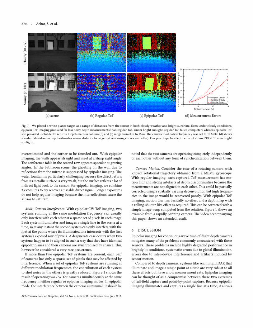
Figure 7 quantitatively compares our sensor prototype operatingoutdoors in regular ToF and epipolar ToF imaging modes undercloudy and sunny conditions. Regular ToF mode performs poorlyin bright sunlight, while epipolar ToF is considerably more robust.Figure 8 shows an example scene with both strong ambient lightand global illumination e�ects.
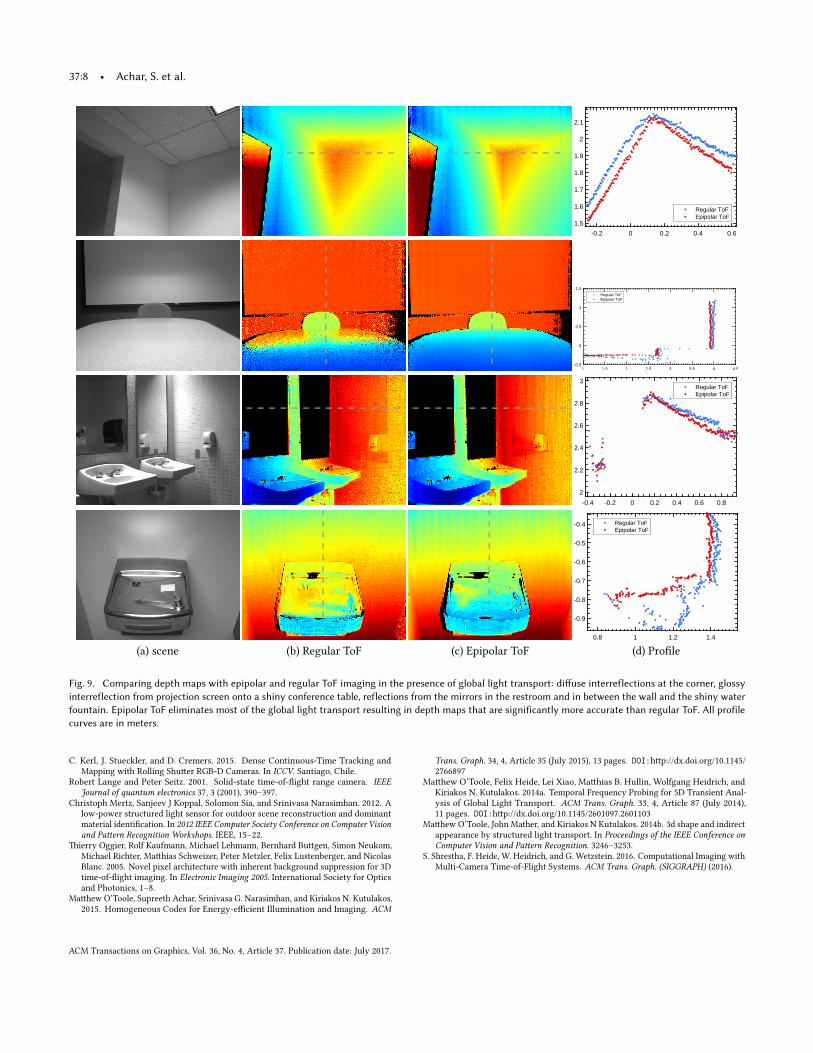
Global Illumination. Figure 9 demonstrates the ability of epipo-lar imaging to suppress the e�ects of global illumination in a fewcommon indoor environments. �ese results are generated using asingle modulation frequency (24 MHz). In regular ToF mode, di�useinterre�ections between the walls and ceiling cause depths to be
ACM Transactions on Graphics, Vol. 36, No. 4, Article 37. Publication date: July 2017.
37:6 • Achar, S. et al.Cl
oudy
(10k
lx)
Distance to target (m)0 5 10 15S
td. D
ev. o
f Dep
th M
easu
rem
ent (
cm)
0
10
20
30
40
50
Regular: CloudyEpipolar: CloudyEpipolar: SunnySu
nny
(70k
lx)
(a) scene (b) Regular ToF (c) Epipolar ToF (d) Measurement Errors
Fig. 7. We placed a white planar target at a range of distances from the sensor in both cloudy weather and bright sunshine. Even under cloudy conditions,epipolar ToF imaging produced far less noisy depth measurements than regular ToF. Under bright sunlight, regular ToF failed completely whereas epipolar ToFstill provided useful depth returns. Depth maps in column (b) and (c) range from 0 m to 15 m. The camera modulation frequency was set to 10 MHz. (d) showsstandard deviation in depth estimates versus distance to target (slower rising curves are be�er). Our prototype has depth error of around 3% at 10 m in brightsunlight.
overestimated and the corner to be rounded out. With epipolarimaging, the walls appear straight and meet at a sharp right angle.�e conference table in the second row appears specular at grazingangles. In the bathroom scene, the ghosting on the wall due tore�ections from the mirror is suppressed by epipolar imaging. �ewater fountain is particularly challenging because the direct returnfrom its metallic surface is very weak, but the surface re�ects a lot ofindirect light back to the sensor. For epipolar imaging, we combine3 exposures to try recover a useable direct signal. Longer exposuresdo not help regular imaging because the interre�ections cause thesensor to saturate.
Multi-Camera Interference. With epipolar CW-ToF imaging, twosystems running at the same modulation frequency can usuallyonly interfere with each other at a sparse set of pixels in each image.Each system illuminates and images a single line in the scene at atime, so at any instant the second system can only interfere with the�rst at the points where its illuminated line intersects with the �rstsystem’s exposed row of pixels. A degenerate case occurs when twosystems happen to be aligned in such a way that they have identicalepipolar planes and their cameras are synchronized by chance. �is,however be considered a very rare occurrence.
If more than two epipolar ToF systems are present, each pairof cameras has only a sparse set of pixels that may be a�ected byinterference. When a set of epipolar ToF systems are running atdi�erent modulation frequencies, the contribution of each systemto shot noise in the others is greatly reduced. Figure 1 shows theresult of operating two CW-ToF cameras simultaneously at the samefrequency in either regular or epipolar imaging modes. In epipolarmode, the interference between the cameras is minimal. It should be
noted that the two cameras are operating completely independentlyof each other without any form of synchronization between them.
Camera Motion. Consider the case of a rotating camera withknown rotational trajectory obtained from a MEMS gyroscope.With regular imaging, each captured ToF measurement has mo-tion blur and strong artefacts at depth discontinuities because themeasurements are not aligned to each other. �is could be partiallycorrected using a spatially varying deconvolution but high frequen-cies in the image would be recovered poorly. With epipolar ToFimaging, motion blur has basically no e�ect and a depth map witha rolling-shu�er-like e�ect is acquired. �is can be corrected with asimple image warp computed from the rotation. Figure 1 shows anexample from a rapidly panning camera. �e video accompanyingthis paper shows an extended result.
6 DISCUSSIONEpipolar imaging for continuous-wave time-of-�ight depth camerasmitigates many of the problems commonly encountered with thesesensors. �ese problems include highly degraded performance inbrightly lit conditions, systematic errors due to global illumination,errors due to inter-device interference and artifacts induced bysensor motion.
Compared to depth cameras, systems like scanning LIDAR thatilluminate and image a single point at a time are very robust to allthese e�ects but have a low measurement rate. Epipolar imagingcan be thought of as a compromise between these two extremesof full-�eld capture and point-by-point capture. Because epipolarimaging illuminates and captures a single line at a time, it allows
ACM Transactions on Graphics, Vol. 36, No. 4, Article 37. Publication date: July 2017.
Epipolar Time-of-Flight Imaging • 37:7
Lamp O� Lamp On
Scen
eRe
gula
rToF
Epip
olar
ToF
Fig. 8. Epipolar ToF imaging provides accurate depth measurements fromthe surface of the light bulbs even when they are turned on. Also note howreflections from the table’s surface cause errors with regular ToF, but theseare suppressed with epipolar imaging.
a depth camera to have most of the robustness of point scanningwhile still having a high measurement rate.
Cycling through multiple phases or pa�erns at one row beforeproceeding to the next row is directly applicable to structured lightas well. Such a scheme would make it possible to apply multi-imagestructured light methods to dynamic scenes for generating high-quality depth maps where currently only single-shot methods canbe used.
In our prototype, the scanning mirror follows a sawtooth pa�ernand captures rows in an ordered sequence. However, with a fasterscanning mirror, pseudo-random row sampling strategies couldbe implemented that might allow epipolar imaging to be used inconjunction with compressed sensing or similar techniques. �iswould allow recovery of temporally super-resolved depth maps offast-moving scenes.
ACKNOWLEDGMENTS�is work is sponsored by the O�ce of Naval Research (GrantN000141512358, DURIP N000141612906), the National Aeronauticsand Space Administration (Grant NNX16AD98G), the Defense Ad-vanced Research Projects Agency (REVEAL Grant HR00111620021)
�antity Symbol Formula Valuelaser peak power P 700 mWlaser wavelength λ 658 nmlaser spot diameter d 0.4 cmlaser horizontal fanout θx 0.785 radlaser vertical fanout θy 0.002 radeye-laser distance zilluminated width w (z) d + zθxilluminated height h(z) d + zθyilluminated area A(z) w (z)h(z)exposure duration texp 100 µsenergy per exposure E 1/
√2Ptexp 49.5 µW
energy density limit MPE 1.80 µJ/cm2
eye safe distance zs A(zs ) =E
MPE 66 cmTable 1. The maximal permissible exposure (MPE) is the highest safe energydensity for a light source. The rules for computing MPE depend on exposuretime and wavelength amongst other factors. Our current prototype is eyesafe at distances greater than 66 cm. A near-infrared (850 nm) version ofour current prototype would be eye safe at distances greater than 40 cm.We designed the laser sheet projector so that its horizontal fanout anglematches the camera’s horizontal field of view and the vertical fanout angleis slightly less than the angle covered by a camera pixel.
and the Natural Sciences and Engineering Reseach Council of Canada(NSERC) under the RPGIN and SPG programs. J. Bartels was sup-ported by NASA fellowship NNX14AM53H.
�e authors would like to thank Dr. Sandu Sonoc, Laser SafetyO�cer at the University of Toronto for his help with the laser safetycalculations.
REFERENCESHatem Alismail, L Douglas Baker, and Bre� Browning. 2014. Continuous trajectory
estimation for 3D SLAM from actuated lidar. In 2014 IEEE International Conferenceon Robotics and Automation (ICRA). IEEE, 6096–6101.
American National Standards Institute. 2014. American National Standard for Safe Useof Lasers Z136.1. Laser Institute of America.
Simon Baker, Eric Benne�, Sing Bing Kang, and Richard Szeliski. 2010. Removingrolling shu�er wobble. In Computer Vision and Pa�ern Recognition (CVPR), 2010IEEE Conference on. IEEE, 2392–2399.
Oliver S Cossairt, Nathan Matsuda, and Mohit Gupta. 2015. Motion Contrast 3DScanning. In Computational Optical Sensing and Imaging. Optical Society of America,CT2E–1.
A. A. Dorrington, J. P. Godbaz, M. J. Cree, A. D. Payne, and L. V. Streeter. 2011. Separatingtrue range measurements from multi-path and sca�ering interference in commercialrange cameras. (2011). DOI:h�p://dx.doi.org/10.1117/12.876586
Rob Fergus, Barun Singh, Aaron Hertzmann, Sam T Roweis, and William T Freeman.2006. Removing camera shake from a single photograph. In ACM Transactions onGraphics (TOG), Vol. 25. ACM, 787–794.
Mohit Gupta, Shree K. Nayar, Ma�hias B. Hullin, and Jaime Martın. 2015. PhasorImaging: A Generalization Of Correlation-Based Time-of-Flight Imaging. ACMTransactions on Graphics 34 (2015).
Mohit Gupta, Qi Yin, and Shree K Nayar. 2013. Structured Light In Sunlight. InternationalConference on Computer Vision (2013).
Felix Heide, Lei Xiao, Andreas Kolb, Ma�hias B. Hullin, and Wolfgang Heidrich.2014. Imaging in sca�ering media using correlation image sensors and sparseconvolutional coding. Opt. Express 22, 21 (Oct 2014), 26338–26350. DOI:h�p://dx.doi.org/10.1364/OE.22.026338
Achuta Kadambi, Refael Whyte, Ayush Bhandari, Lee Streeter, Christopher Barsi,Adrian Dorrington, and Ramesh Raskar. 2013. Coded Time of Flight Cameras:Sparse Deconvolution to Address Multipath Interference and Recover Time Pro�les.ACM Trans. Graph. 32, 6, Article 167 (Nov. 2013), 10 pages. DOI:h�p://dx.doi.org/10.1145/2508363.2508428
ACM Transactions on Graphics, Vol. 36, No. 4, Article 37. Publication date: July 2017.
37:8 • Achar, S. et al.
-0.2 0 0.2 0.4 0.6
1.5
1.6
1.7
1.8
1.9
2
2.1
Regular ToFEpipolar ToF
1 1.5 2 2.5 3 3.5 4 4.5-0.5
0
0.5
1
1.5Regular ToFEpipolar ToF
-0.4 -0.2 0 0.2 0.4 0.6 0.8
2
2.2
2.4
2.6
2.8
3Regular ToFEpipolar ToF
0.8 1 1.2 1.4
-0.9
-0.8
-0.7
-0.6
-0.5
-0.4 Regular ToFEpipolar ToF
(a) scene (b) Regular ToF (c) Epipolar ToF (d) Pro�le
Fig. 9. Comparing depth maps with epipolar and regular ToF imaging in the presence of global light transport: di�use interreflections at the corner, glossyinterreflection from projection screen onto a shiny conference table, reflections from the mirrors in the restroom and in between the wall and the shiny waterfountain. Epipolar ToF eliminates most of the global light transport resulting in depth maps that are significantly more accurate than regular ToF. All profilecurves are in meters.
C. Kerl, J. Stueckler, and D. Cremers. 2015. Dense Continuous-Time Tracking andMapping with Rolling Shu�er RGB-D Cameras. In ICCV. Santiago, Chile.
Robert Lange and Peter Seitz. 2001. Solid-state time-of-�ight range camera. IEEEJournal of quantum electronics 37, 3 (2001), 390–397.
Christoph Mertz, Sanjeev J Koppal, Solomon Sia, and Srinivasa Narasimhan. 2012. Alow-power structured light sensor for outdoor scene reconstruction and dominantmaterial identi�cation. In 2012 IEEE Computer Society Conference on Computer Visionand Pa�ern Recognition Workshops. IEEE, 15–22.
�ierry Oggier, Rolf Kaufmann, Michael Lehmann, Bernhard Bu�gen, Simon Neukom,Michael Richter, Ma�hias Schweizer, Peter Metzler, Felix Lustenberger, and NicolasBlanc. 2005. Novel pixel architecture with inherent background suppression for 3Dtime-of-�ight imaging. In Electronic Imaging 2005. International Society for Opticsand Photonics, 1–8.
Ma�hew O’Toole, Supreeth Achar, Srinivasa G. Narasimhan, and Kiriakos N. Kutulakos.2015. Homogeneous Codes for Energy-e�cient Illumination and Imaging. ACM
Trans. Graph. 34, 4, Article 35 (July 2015), 13 pages. DOI:h�p://dx.doi.org/10.1145/2766897
Ma�hew O’Toole, Felix Heide, Lei Xiao, Ma�hias B. Hullin, Wolfgang Heidrich, andKiriakos N. Kutulakos. 2014a. Temporal Frequency Probing for 5D Transient Anal-ysis of Global Light Transport. ACM Trans. Graph. 33, 4, Article 87 (July 2014),11 pages. DOI:h�p://dx.doi.org/10.1145/2601097.2601103
Ma�hew O’Toole, John Mather, and Kiriakos N Kutulakos. 2014b. 3d shape and indirectappearance by structured light transport. In Proceedings of the IEEE Conference onComputer Vision and Pa�ern Recognition. 3246–3253.
S. Shrestha, F. Heide, W. Heidrich, and G. Wetzstein. 2016. Computational Imaging withMulti-Camera Time-of-Flight Systems. ACM Trans. Graph. (SIGGRAPH) (2016).
ACM Transactions on Graphics, Vol. 36, No. 4, Article 37. Publication date: July 2017.


![1 Mathematical Descriptions of Imaging Systems · SIMG-716 Linear Imaging Mathematics I 01 - Motivation 1 Mathematical Descriptions of Imaging Systems Input to Imaging System: f[x,y,z,λ,t]](https://static.fdocument.org/doc/165x107/60110d4541d0412d03031368/1-mathematical-descriptions-of-imaging-simg-716-linear-imaging-mathematics-i-01.jpg)