![FAN7711 Ballast Control Integrated Circuit - Digi-Key Sheets/Fairchild PDFs/FAN7711.pdf · FAN7711 Ballast Control Integrated Circuit) 1 3 0 circuit [.] ...](https://static.fdocument.org/doc/165x107/5acfdb947f8b9a1d328d8e40/fan7711-ballast-control-integrated-circuit-digi-key-sheetsfairchild-pdfsfan7711pdffan7711.jpg)
e’Œšˆ sˆ˜Œˆ™ - Heat-Timer Corporation | Automated...
20
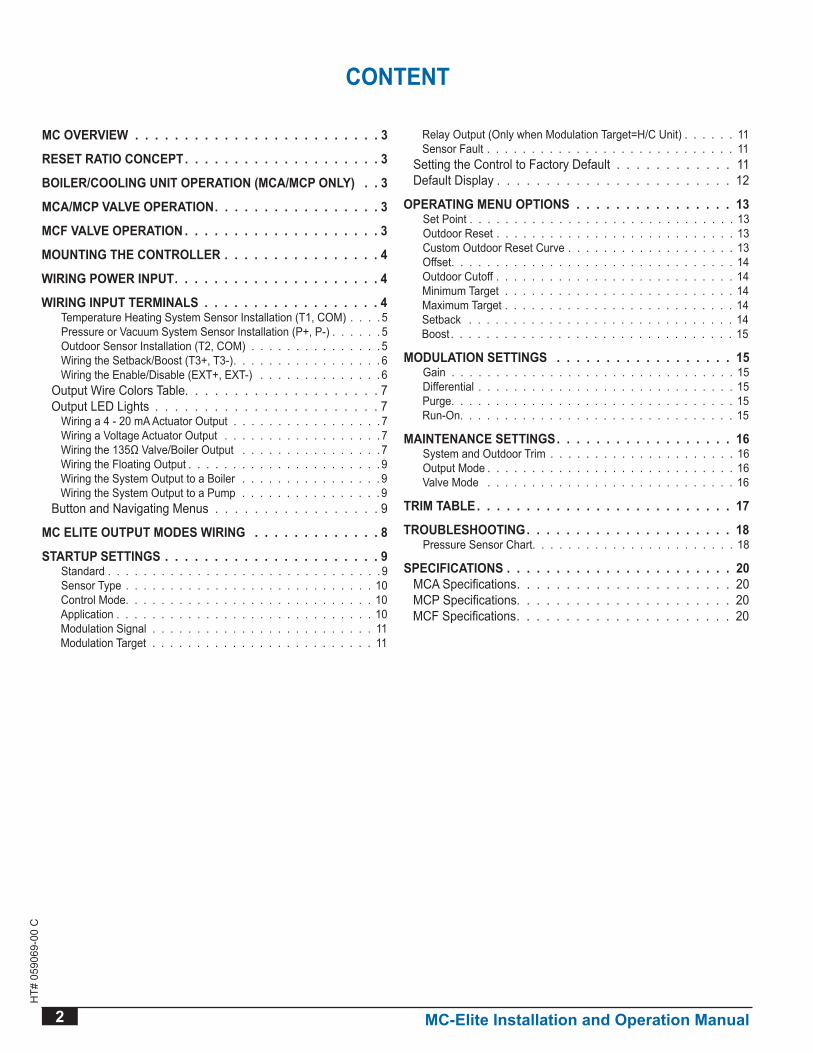
HT# 059069-00 C INSTALLATION AND OPERATION INSTRUCTIONS MC SERIES DIGI-ELITE MODULATING CONTROLS ® WARNING This Heat-Timer control is strictly an operating control; it should never be used as a primary limit or safety control. All equipment must have its own certified limit and safety controls required by code. The installer must verify proper operation and correct any safety problems related to the installation of this Heat-Timer control. This control must be installed by a licensed electrician. Current/Voltage (MCa), 135Ω (MCP), Floating (MCF) For teMPerature, Pressure, VaCuuM, or HuMidity System Decrease ® SYSTEM = 147 o F TARGET = 150 o F DECREASE SYSTEM INCREASE Yellow (System/Boiler Output) 2 Line Alphanumeric Display Displays sensor values and menu settings Output Lights indicate output status Display Section Locking Screws Black (120VAC power) Blue Red White Modulating Output
Transcript of e’Œšˆ sˆ˜Œˆ™ - Heat-Timer Corporation | Automated...

HT#
059
069-
00 C
INSTALLATION AND OPERATION INSTRUCTIONS
MC SerieS DiGi-eliteMODULATINg CONTROLS
®
e’Œšˆ sˆ˜Œˆ™
WARNINgThis Heat-Timer control is strictly an operating control; it should never be used as a primary limit or safety control. All equipment must have its own certified limit and safety controls required by code. The installer must verify proper operation and correct any safety problems related to the installation of this Heat-Timer control.
This control must be installed by a licensed electrician.
Current/Voltage (MCa), 135Ω (MCP), Floating (MCF)For teMPerature, Pressure, VaCuuM, or HuMidity
SystemDecrease
®
SYSTEM = 147oF
TARGET = 150oF
DECREASE SYSTEMINCREASE
Yellow(System/Boiler Output)
2 Line Alphanumeric DisplayDisplays sensor values and
menu settings
Output Lights indicateoutput status
Display Section Locking Screws
Black (120VAC power)
Blue
Red
White
Modulating Output
2 MC-Elite Installation and Operation Manual
HT#
059
069-
00 C
MC OvERvIEW . . . . . . . . . . . . . . . . . . . . . . . . . 3
RESET RATIO CONCEPT. . . . . . . . . . . . . . . . . . . . 3
Boiler/Cooling unit oPeration (MCa/MCP only) . . 3
MCA/MCP vALvE OPERATION. . . . . . . . . . . . . . . . . 3
MCF ValVe oPeration . . . . . . . . . . . . . . . . . . . . 3
MOUNTINg THE CONTROLLER . . . . . . . . . . . . . . . . 4
WIRINg POWER INPUT. . . . . . . . . . . . . . . . . . . . . 4
WIRINg INPUT TERMINALS . . . . . . . . . . . . . . . . . . 4Temperature Heating System Sensor Installation (T1, COM) 5Pressure or Vacuum System Sensor Installation (P+, P-) 5Outdoor Sensor Installation (T2, COM) 5Wiring the Setback/Boost (T3+, T3-) 6Wiring the Enable/Disable (EXT+, EXT-) 6
Output Wire Colors Table 7Output LED Lights 7
Wiring a 4 - 20 mA Actuator Output 7Wiring a Voltage Actuator Output 7Wiring the 135Ω Valve/Boiler Output 7Wiring the Floating Output 9Wiring the System Output to a Boiler 9Wiring the System Output to a Pump 9
Button and Navigating Menus 9
MC ELITE OUTPUT MODES WIRINg . . . . . . . . . . . . . 8
STARTUP SETTINgS . . . . . . . . . . . . . . . . . . . . . . 9Standard 9Sensor Type 10Control Mode 10Application 10Modulation Signal 11Modulation Target 11
Relay Output (Only when Modulation Target=H/C Unit) 11Sensor Fault 11
Setting the Control to Factory Default 11Default Display 12
OPERATINg MENU OPTIONS . . . . . . . . . . . . . . . . 13Set Point 13Outdoor Reset 13Custom Outdoor Reset Curve 13Offset 14Outdoor Cutoff 14Minimum Target 14Maximum Target 14Setback 14Boost 15
MODULATION SETTINgS . . . . . . . . . . . . . . . . . . 15Gain 15Differential 15Purge 15Run-On 15
MAINTENANCE SETTINgS. . . . . . . . . . . . . . . . . . 16System and Outdoor Trim 16Output Mode 16Valve Mode 16
TRIM TAbLE. . . . . . . . . . . . . . . . . . . . . . . . . . 17
TROUbLESHOOTINg. . . . . . . . . . . . . . . . . . . . . 18Pressure Sensor Chart 18
sPeCiFiCations . . . . . . . . . . . . . . . . . . . . . . . 20MCA Specifications 20MCP Specifications 20MCF Specifications 20
CONTENT
MC-Elite Installation and Operation Manual 3
HT#
059
069-
00 C
MC OvERvIEWThe MC Elite Series controls modulating valves, motors, variable speed drives, or boilers to accurately maintain a set point; temperature, pressure, vacuum, or humidity. Well suited for radiant and process applications, the MC Elite changes the position of a valve, motor, variable speed drive, or modulating boiler in response to changes in sensor readings based on a PID logic. Like all Digi-Span Elites , the MC constantly displays the sensor’s temperature, pressure, vacuum, or humidity and the target set point. Additional control parameters can also be displayed with the simple press of a button. LED lights indicates the MC Elite modulating direction.
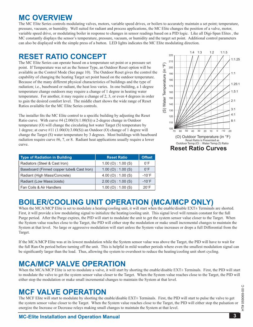
RESET RATIO CONCEPTThe MC Elite Series can operate based on a temperature set point or a pressure set point. If Temperature was set as the Sensor Type, an Outdoor Reset option will be available as the Control Mode (See page 10). The Outdoor Reset gives the control the capability of changing the heating Target set point based on the outdoor temperature. Because of the many different physical characteristics of buildings and the type of radiation; i.e., baseboard or radiant, the heat loss varies. In one building, a 1-degree temperature change outdoors may require a change of 1 degree in heating water temperature. For another, it may require a change of 2, 3, or even 4 degrees in order to gain the desired comfort level. The middle chart shows the wide range of Reset Ratios available for the MC Elite Series controls.
The installer fits the MC Elite control to a specific building by adjusting the Reset Ratio curve. With curve #4 (2.00(O):1.00(S)) a 2-degree change in Outdoor temperature (O) will change the circulating hot water Target (S) temperature by 1 degree; at curve #11 (1.00(O):3.00(S)) an Outdoor (O) change of 1 degree will change the Target (S) water temperature by 3 degrees. Most buildings with baseboard radiation require curve #6, 7, or 8. Radiant heat applications usually require a lower curve.
Type of Radiation in building Reset Ratio OffsetRadiators (Steel & Cast Iron) 1 00 (O) : 1 00 (S) 0˚FBaseboard (Finned copper tube& Cast Iron) 1 00 (O) : 1 00 (S) 0˚FRadiant (High Mass/Concrete) 4 00 (O) : 1 00 (S) -10˚FRadiant (Low Mass/Joists) 2 00 (O) : 1 00 (S) -10˚FFan Coils & Air Handlers 1 00 (O) : 1 00 (S) 20˚F
Boiler/Cooling unit oPeration (MCa/MCP only)When the MCA/MCP Elite is set to modulate a heating/cooling unit, it will start when the enable/disable EXT± Terminals are shorted. First, it will provide a low modulating signal to initialize the heating/cooling unit. This signal level will remain constant for the full Purge period. After the Purge expires, the PID will start to modulate the unit to get the system sensor value closer to the Target. When the System value reaches close to the Target, the PID will either stop the modulation or make small incremental changes to maintain the System at that level. No large or aggressive modulation will start unless the System value increases or drops a full Differential from the Target.
If the MCA/MCP Elite was at its lowest modulation while the System sensor value was above the Target, the PID will have to wait for the full Run-On period before turning off the unit. This is helpful in mild weather periods where even the smallest modulation signal can be significantly larger than the load. Thus, allowing the system to overshoot to reduce the heating/cooling unit short cycling.
MCA/MCP vALvE OPERATIONWhen the MCA/MCP Elite is set to modulate a valve, it will start by shorting the enable/disable EXT± Terminals. First, the PID will start to modulate the valve to get the system sensor value closer to the Target. When the System value reaches close to the Target, the PID will either stop the modulation or make small incremental changes to maintain the System at that level.
MCF ValVe oPerationThe MCF Elite will start to modulate by shorting the enable/disable EXT± Terminals. First, the PID will start to pulse the valve to get the system sensor value closer to the Target. When the System value reaches close to the Target, the PID will either stop the pulsation or energize the Increase or Decrease relays making small changes to maintain the System at that level.
(O) Outdoor Temperature (in °F)70 60 50 40 2030 0 -1010 -20
100
120
110
130
140
150
160
180
170
190
200
210
2201:3 1:2 1:1.5
1:1.25
1:1
1.25:1
1.5:1
2:1
3:1
4:1
(S) W
ater
Tem
pera
ture
(in
°F)
Reset Ratio CurvesReset Ratio is Presented as
Outdoor Temp.(O) : Water Temp.(S) Ratio
1:4
8:1
4 MC-Elite Installation and Operation Manual
HT#
059
069-
00 C
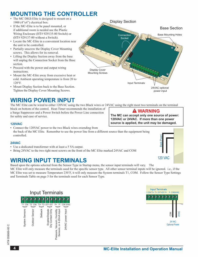
MOUNTINg THE CONTROLLER• The MC DIGI-Elite is designed to mount on a
1900 (4”x4”) electrical box.• If the MC-Elite is to be panel mounted, or
if additional room is needed use the Plastic Wiring Enclosure (HT# 929135-00 Switch) or (HT# 929137-00 without a Switch).
• Locate the MC-Elite in a convenient location near the unit to be controlled.
• Partially unscrew the Display Cover Mounting screws. This allows for its removal.
• Lifting the Display Section away from the base will unplug the Connection Socket from the Base section.
• Proceed with the power and output wiring instructions.
• Mount the MC-Elite away from excessive heat or cold. Ambient operating temperature is from 20 to 120°F.
• Mount Display Section back to the Base Section. Tighten the Display Cover Mounting Screws.
WIRINg POWER INPUTThe MC Elite can be wired to either 120VAC using the two Black wires or 24VAC using the right most two terminals on the terminal block on bottom of the control. Heat-Timer recommends the installation of a Surge Suppressor and a Power Switch before the Power Line connection for safety and ease of service.
120vAC• Connect the 120VAC power to the two Black wires extending from
the back of the MC Elite. Remember to use the power line from a different source than the equipment being controlled.
24vAC• Use a dedicated transformer with at least a 5 VA output.• Bring 24VAC to the two right most screws on the front of the MC Elite marked 24VAC and COM
WIRINg INPUT TERMINALSBased upon the options selected from the Sensor Type in Startup menu, the sensor input terminals will vary. The MC Elite will only measure the terminals used for the specific sensor type. All other sensor terminal inputs will be ignored. i.e., if the MC Elite was set to measure Temperature 230˚F, it will only measure the System terminals T1, COM. Follow the Sensor Type Settings and Terminals Table on page 5 for the terminals used for each Sensor Type.
WARNINgThe MC can accept only one source of power: 120vAC or 24vAC. If more than one power source is applied, the unit may be damaged.
Display CoverMounting Screws
Display Section
Base SectionBase Mounting Holes
Input Terminals
24VAC optional power input
ConnectionSocket
T1 T2 T3+COM COM T3- EXT+ EXT- P+ P- COM 24VAC
Input Terminals
Sys
tem
Sen
sors
Pre
ssur
e, V
acuu
m, H
umid
ityS
enso
rs, o
r 4-2
0mA
inpu
t
Ena
ble/
Dis
bale
Dry
Con
tact
Onl
y
Set
back
Out
door
Sen
sor
24VA
C p
ower
Inpu
t
SystemDecrease
®
SYSTEM = 147oF
TARGET = 150oF
DECREASE SYSTEMINCREASE
120 VACBl
ack (
Powe
r)SystemDecrease
®
SYSTEM = 147oF
TARGET = 150oF
DECREASE SYSTEMINCREASE
24 VACOptional Power
COM
24VA
C
T1 T2COM T3+COM COM24VACEXT+EXT-T3- P+ P-Input Terminals
MC-Elite Installation and Operation Manual 5
HT#
059
069-
00 C
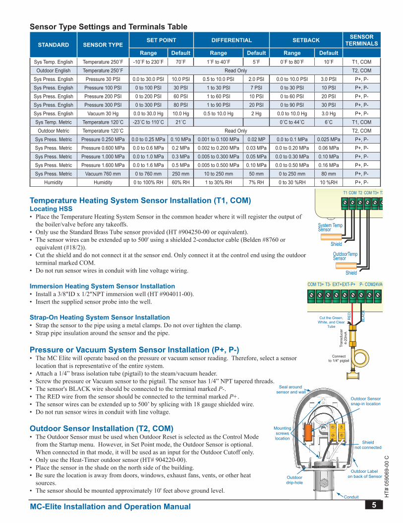
Sensor Type Settings and Terminals Table
STANDARD sensor tyPeSET POINT diFFerential SETbACK SENSOR
TERMINALSRange Default Range Default Range Default
Sys Temp English Temperature 250˚F -10˚F to 230˚F 70˚F 1˚F to 40˚F 5˚F 0˚F to 80˚F 10˚F T1, COMOutdoor English Temperature 250˚F Read Only T2, COM
Sys Press English Pressure 30 PSI 0 0 to 30 0 PSI 10 0 PSI 0 5 to 10 0 PSI 2 0 PSI 0 0 to 10 0 PSI 3 0 PSI P+, P-Sys Press English Pressure 100 PSI 0 to 100 PSI 30 PSI 1 to 30 PSI 7 PSI 0 to 30 PSI 10 PSI P+, P-Sys Press English Pressure 200 PSI 0 to 200 PSI 60 PSI 1 to 60 PSI 10 PSI 0 to 60 PSI 20 PSI P+, P-Sys Press English Pressure 300 PSI 0 to 300 PSI 80 PSI 1 to 90 PSI 20 PSI 0 to 90 PSI 30 PSI P+, P-Sys Press English Vacuum 30 Hg 0 0 to 30 0 Hg 10 0 Hg 0 5 to 10 0 Hg 2 Hg 0 0 to 10 0 Hg 3 0 Hg P+, P-Sys Temp Metric Temperature 120˚C -23˚C to 110˚C 21˚C 0˚C to 44˚C 6˚C T1, COMOutdoor Metric Temperature 120˚C Read Only T2, COM
Sys Press Metric Pressure 0 250 MPa 0 0 to 0 25 MPa 0 10 MPa 0 001 to 0 100 MPa 0 02 MP 0 0 to 0 1 MPa 0 025 MPa P+, P-Sys Press Metric Pressure 0 600 MPa 0 0 to 0 6 MPa 0 2 MPa 0 002 to 0 200 MPa 0 03 MPa 0 0 to 0 20 MPa 0 06 MPa P+, P-Sys Press Metric Pressure 1 000 MPa 0 0 to 1 0 MPa 0 3 MPa 0 005 to 0 300 MPa 0 05 MPa 0 0 to 0 30 MPa 0 10 MPa P+, P-Sys Press Metric Pressure 1 600 MPa 0 0 to 1 6 MPa 0 5 MPa 0 005 to 0 500 MPa 0 10 MPa 0 0 to 0 50 MPa 0 16 MPa P+, P-Sys Press Metric Vacuum 760 mm 0 to 760 mm 250 mm 10 to 250 mm 50 mm 0 to 250 mm 80 mm P+, P-
Humidity Humidity 0 to 100% RH 60% RH 1 to 30% RH 7% RH 0 to 30 %RH 10 %RH P+, P-
Temperature Heating System Sensor Installation (T1, COM)Locating HSS• Place the Temperature Heating System Sensor in the common header where it will register the output of
the boiler/valve before any takeoffs.• Only use the Standard Brass Tube sensor provided (HT #904250-00 or equivalent).• The sensor wires can be extended up to 500' using a shielded 2-conductor cable (Belden #8760 or
equivalent (#18/2)).• Cut the shield and do not connect it at the sensor end. Only connect it at the control end using the outdoor
terminal marked COM.• Do not run sensor wires in conduit with line voltage wiring.
Immersion Heating System Sensor Installation• Install a 3/8"ID x 1/2"NPT immersion well (HT #904011-00).• Insert the supplied sensor probe into the well.
Strap-On Heating System Sensor Installation• Strap the sensor to the pipe using a metal clamps. Do not over tighten the clamp.• Strap pipe insulation around the sensor and the pipe.
Pressure or vacuum System Sensor Installation (P+, P-)• The MC Elite will operate based on the pressure or vacuum sensor reading. Therefore, select a sensor
location that is representative of the entire system.• Attach a 1/4” brass isolation tube (pigtail) to the steam/vacuum header.• Screw the pressure or Vacuum sensor to the pigtail. The sensor has 1/4” NPT tapered threads.• The sensor's BLACK wire should be connected to the terminal marked P-.• The RED wire from the sensor should be connected to the terminal marked P+.• The sensor wires can be extended up to 500’ by splicing with 18 gauge shielded wire.• Do not run sensor wires in conduit with line voltage.
Outdoor Sensor Installation (T2, COM)• The Outdoor Sensor must be used when Outdoor Reset is selected as the Control Mode
from the Startup menu. However, in Set Point mode, the Outdoor Sensor is optional. When connected in that mode, it will be used as an input for the Outdoor Cutoff only.
• Only use the Heat-Timer outdoor sensor (HT# 904220-00).• Place the sensor in the shade on the north side of the building.• Be sure the location is away from doors, windows, exhaust fans, vents, or other heat
sources.• The sensor should be mounted approximately 10' feet above ground level.
SystemDecrease
®
SYSTEM = 147oF
TARGET = 150oF
DECREASE SYSTEMINCREASE
System TempSensor
Shield
OutdoorTempSensor
Shield
T1 T2COM T3+COM COM24VACEXT+EXT-T3- P+ P-Input Terminals
SystemDecrease
®
SYSTEM = 147oF
TARGET = 150oF
DECREASE SYSTEMINCREASE
Cut the Green,White, and Clear
Tube
Connectto 1/4" pigtail
BLA
CK
RE
D
Tran
sduc
er4-
20m
A
T1 T2COM T3+COM COM24VACEXT+EXT-T3- P+ P-Input Terminals
Outdoor Sensorsnap-in location
Shieldnot connected
Conduit
Outdoor Label on back of Sensor
Outdoor Sensor
Mountingscrewslocation
Seal around sensor and wall
Outdoordrip-hole
Conduit
Well
Sensorin well
6 MC-Elite Installation and Operation Manual
HT#
059
069-
00 C
• Adhere the Outdoor Label provided to the back of the sensor base.• Use the Enclosure Base bottom knockout for the conduit. Use the locknut to hold the conduit and enclosure
base together. Screw the cover to the base.• If screws are used to affix the enclosure to the wall, make sure to seal around the sensor and wall except from
the bottom.• The sensor wires can be extended up to 500' using shielded 2-conductor cable. • Cut the shield and do not connect it at the sensor end. Only connect it at the control end using the outdoor
terminal marked COM.• Do not run sensor wires in conduit with line voltage wiring.
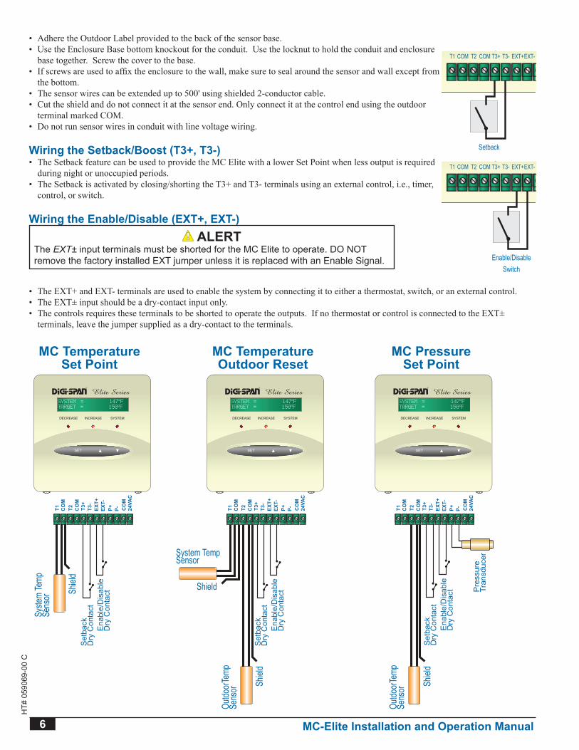
Wiring the Setback/boost (T3+, T3-)• The Setback feature can be used to provide the MC Elite with a lower Set Point when less output is required
during night or unoccupied periods.• The Setback is activated by closing/shorting the T3+ and T3- terminals using an external control, i.e., timer,
control, or switch.
Wiring the Enable/Disable (EXT+, EXT-) ALERT
The EXT± input terminals must be shorted for the MC Elite to operate DO NOT remove the factory installed EXT jumper unless it is replaced with an Enable Signal.
• The EXT+ and EXT- terminals are used to enable the system by connecting it to either a thermostat, switch, or an external control.• The EXT± input should be a dry-contact input only.• The controls requires these terminals to be shorted to operate the outputs. If no thermostat or control is connected to the EXT±
terminals, leave the jumper supplied as a dry-contact to the terminals.
Ena
ble/
Dis
able
Dry
Con
tact
MC TemperatureSet Point
MC TemperatureOutdoor Reset
MC PressureSet Point
Set
back
Dry
Con
tact
Ena
ble/
Dis
able
Dry
Con
tact
Set
back
Dry
Con
tact
Pre
ssur
eTr
ansd
ucer
Ena
ble/
Dis
able
Dry
Con
tact
Set
back
Dry
Con
tact
Cut the Green,White, and Clear
Tube
Connectto 1/4" pigtail
BLA
CK
RE
D
Tran
sduc
er4-
20m
A
Syste
m Te
mpSe
nsor Sh
ield
Outdo
orTe
mpSe
nsor Sh
ield
Outdo
orTe
mpSe
nsor Sh
ield
System TempSensor
Shield
SystemDecrease
®
SYSTEM = 147oF
TARGET = 150oF
DECREASE SYSTEMINCREASE SystemDecrease
®
SYSTEM = 147oF
TARGET = 150oF
DECREASE SYSTEMINCREASE SystemDecrease
®
SYSTEM = 147oF
TARGET = 150oF
DECREASE SYSTEMINCREASE
T1 T2CO
M
CO
MT3
+T3
-EX
T+EX
T-P+ P- C
OM
24VA
C
T1 T2CO
M
CO
MT3
+T3
-EX
T+EX
T-P+ P- C
OM
24VA
C
T1 T2CO
M
CO
MT3
+T3
-EX
T+EX
T-P+ P- C
OM
24VA
C
T1 T2CO
M
CO
MT3
+T3
-EX
T+EX
T-P+ P- C
OM
24VA
CE
nabl
e/D
isab
leD
ry C
onta
ct
MC TemperatureSet Point
MC TemperatureOutdoor Reset
MC PressureSet Point
Set
back
Dry
Con
tact
Ena
ble/
Dis
able
Dry
Con
tact
Set
back
Dry
Con
tact
Pre
ssur
eTr
ansd
ucer
Ena
ble/
Dis
able
Dry
Con
tact
Set
back
Dry
Con
tact
Cut the Green,White, and Clear
Tube
Connectto 1/4" pigtail
BLA
CK
RE
D
Tran
sduc
er4-
20m
A
Syste
m Te
mpSe
nsor Sh
ield
Outdo
orTe
mpSe
nsor Sh
ield
Outdo
orTe
mpSe
nsor Sh
ield
System TempSensor
Shield
SystemDecrease
®
SYSTEM = 147oF
TARGET = 150oF
DECREASE SYSTEMINCREASE SystemDecrease
®
SYSTEM = 147oF
TARGET = 150oF
DECREASE SYSTEMINCREASE SystemDecrease
®
SYSTEM = 147oF
TARGET = 150oF
DECREASE SYSTEMINCREASE
T1 T2CO
M
CO
MT3
+T3
-EX
T+EX
T-P+ P- C
OM
24VA
C
T1 T2CO
M
CO
MT3
+T3
-EX
T+EX
T-P+ P- C
OM
24VA
C
T1 T2CO
M
CO
MT3
+T3
-EX
T+EX
T-P+ P- C
OM
24VA
C
T1 T2CO
M
CO
MT3
+T3
-EX
T+EX
T-P+ P- C
OM
24VA
C
Ena
ble/
Dis
able
Dry
Con
tact
MC TemperatureSet Point
MC TemperatureOutdoor Reset
MC PressureSet Point
Set
back
Dry
Con
tact
Ena
ble/
Dis
able
Dry
Con
tact
Set
back
Dry
Con
tact
Pre
ssur
eTr
ansd
ucer
Ena
ble/
Dis
able
Dry
Con
tact
Set
back
Dry
Con
tact
Cut the Green,White, and Clear
Tube
Connectto 1/4" pigtail
BLA
CK
RE
D
Tran
sduc
er4-
20m
A
Syste
m Te
mpSe
nsor Sh
ield
Outdo
orTe
mpSe
nsor Sh
ield
Outdo
orTe
mpSe
nsor Sh
ield
System TempSensor
Shield
SystemDecrease
®
SYSTEM = 147oF
TARGET = 150oF
DECREASE SYSTEMINCREASE SystemDecrease
®
SYSTEM = 147oF
TARGET = 150oF
DECREASE SYSTEMINCREASE SystemDecrease
®
SYSTEM = 147oF
TARGET = 150oF
DECREASE SYSTEMINCREASE
T1 T2CO
M
CO
MT3
+T3
-EX
T+EX
T-P+ P- C
OM
24VA
C
T1 T2CO
M
CO
MT3
+T3
-EX
T+EX
T-P+ P- C
OM
24VA
C
T1 T2CO
M
CO
MT3
+T3
-EX
T+EX
T-P+ P- C
OM
24VA
C
T1 T2CO
M
CO
MT3
+T3
-EX
T+EX
T-P+ P- C
OM
24VA
C
SystemDecrease
®
SYSTEM = 147oF
TARGET = 150oF
DECREASE SYSTEMINCREASE
Setback
T1 T2COM T3+COM COM24VACEXT+EXT-T3- P+ P-Input Terminals
SystemDecrease
®
SYSTEM = 147oF
TARGET = 150oF
DECREASE SYSTEMINCREASE
Enable/DisableSwitch
T1 T2COM T3+COM COM24VACEXT+EXT-T3- P+ P-Input Terminals
MC-Elite Installation and Operation Manual 7
HT#
059
069-
00 C
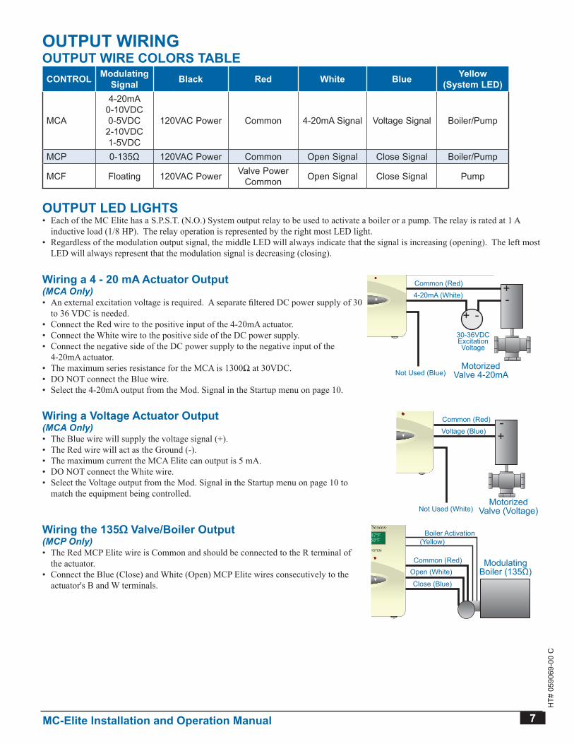
OUTPUT WIRINgOUTPUT WIRE COLORS TAbLECONTROL Modulating
Signal black Red White blue yellow(System LED)
MCA
4-20mA0-10VDC0-5VDC
2-10VDC1-5VDC
120VAC Power Common 4-20mA Signal Voltage Signal Boiler/Pump
MCP 0-135Ω 120VAC Power Common Open Signal Close Signal Boiler/Pump
MCF Floating 120VAC Power Valve Power Common Open Signal Close Signal Pump
OUTPUT LED LIgHTS• Each of the MC Elite has a S.P.S.T. (N.O.) System output relay to be used to activate a boiler or a pump. The relay is rated at 1 A
inductive load (1/8 HP). The relay operation is represented by the right most LED light.• Regardless of the modulation output signal, the middle LED will always indicate that the signal is increasing (opening). The left most
LED will always represent that the modulation signal is decreasing (closing).
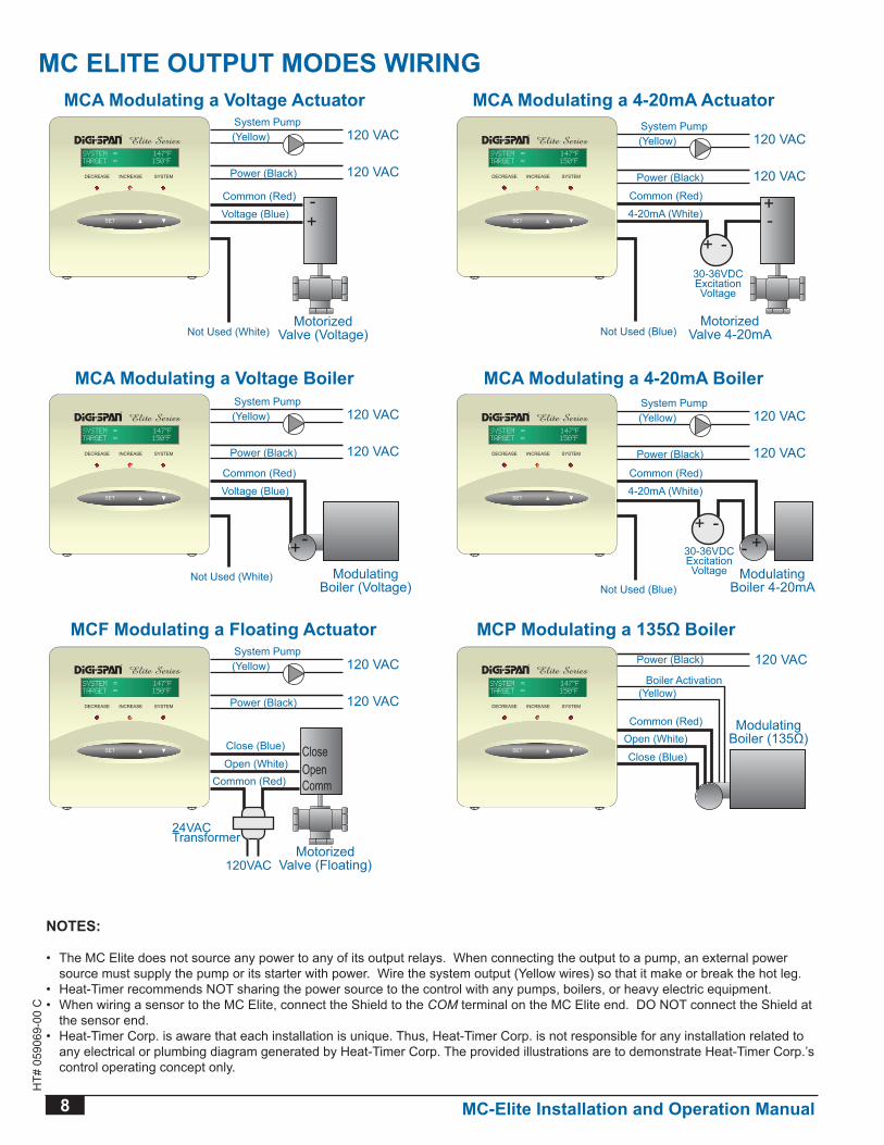
Wiring a 4 - 20 mA Actuator Output(MCA Only)• An external excitation voltage is required. A separate filtered DC power supply of 30
to 36 VDC is needed.• Connect the Red wire to the positive input of the 4-20mA actuator.• Connect the White wire to the positive side of the DC power supply.• Connect the negative side of the DC power supply to the negative input of the
4-20mA actuator.• The maximum series resistance for the MCA is 1300Ω at 30VDC.• DO NOT connect the Blue wire.• Select the 4-20mA output from the Mod. Signal in the Startup menu on page 10.
MotorizedValve 4-20mA
Common (Red)
4-20mA (White)
Not Used (Blue)
+ --+
30-36VDCExcitationVoltage
120 VAC
System Pump
Power (Black)
(Yellow) 120 VAC
MCA Modulating a 4-20mA Actuator
MotorizedValve (Voltage)
Common (Red)
Voltage (Blue)
Not Used (White)
-+
120 VAC
System Pump
Power (Black)
(Yellow) 120 VAC
MCA Modulating a Voltage Actuator
Common (Red)
4-20mA (White)
Not Used (Blue)
30-36VDCExcitationVoltage Modulating
Boiler 4-20mA
- +
120 VAC
System Pump
Power (Black)
(Yellow) 120 VAC
MCA Modulating a 4-20mA Boiler
Common (Red)
Voltage (Blue)
Not Used (White) ModulatingBoiler (Voltage)
-+
120 VAC
System Pump
Power (Black)
(Yellow) 120 VAC
MCA Modulating a Voltage Boiler
120 VACBoiler Activation
Power (Black)
(Yellow)
Common (Red)
Close (Blue)
Open (White)Modulating
Boiler (135Ω)
MCP Modulating a 135Ω Boiler
120 VAC
System Pump
MotorizedValve (Floating)
Power (Black)
(Yellow)
Common (Red)
Close (Blue)
Open (White)CloseOpenComm
24VACTransformer
120VAC
120 VAC
MCF Modulating a Floating Actuator
+ -
SystemDecrease
®
SYSTEM = 147oF
TARGET = 150oF
DECREASE SYSTEMINCREASE SystemDecrease
®
SYSTEM = 147oF
TARGET = 150oF
DECREASE SYSTEMINCREASE
SystemDecrease
®
SYSTEM = 147oF
TARGET = 150oF
DECREASE SYSTEMINCREASE SystemDecrease
®
SYSTEM = 147oF
TARGET = 150oF
DECREASE SYSTEMINCREASE
SystemDecrease
®
SYSTEM = 147oF
TARGET = 150oF
DECREASE SYSTEMINCREASE SystemDecrease
®
SYSTEM = 147oF
TARGET = 150oF
DECREASE SYSTEMINCREASE
Wiring a voltage Actuator Output(MCA Only)• The Blue wire will supply the voltage signal (+).• The Red wire will act as the Ground (-).• The maximum current the MCA Elite can output is 5 mA.• DO NOT connect the White wire.• Select the Voltage output from the Mod. Signal in the Startup menu on page 10 to
match the equipment being controlled.Motorized
Valve 4-20mA
Common (Red)
4-20mA (White)
Not Used (Blue)
+ --+
30-36VDCExcitationVoltage
120 VAC
System Pump
Power (Black)
(Yellow) 120 VAC
MCA Modulating a 4-20mA Actuator
MotorizedValve (Voltage)
Common (Red)
Voltage (Blue)
Not Used (White)
-+
120 VAC
System Pump
Power (Black)
(Yellow) 120 VAC
MCA Modulating a Voltage Actuator
Common (Red)
4-20mA (White)
Not Used (Blue)
30-36VDCExcitationVoltage Modulating
Boiler 4-20mA
- +
120 VAC
System Pump
Power (Black)
(Yellow) 120 VAC
MCA Modulating a 4-20mA Boiler
Common (Red)
Voltage (Blue)
Not Used (White) ModulatingBoiler (Voltage)
-+
120 VAC
System Pump
Power (Black)
(Yellow) 120 VAC
MCA Modulating a Voltage Boiler
120 VACBoiler Activation
Power (Black)
(Yellow)
Common (Red)
Close (Blue)
Open (White)Modulating
Boiler (135Ω)
MCP Modulating a 135Ω Boiler
120 VAC
System Pump
MotorizedValve (Floating)
Power (Black)
(Yellow)
Common (Red)
Close (Blue)
Open (White)CloseOpenComm
24VACTransformer
120VAC
120 VAC
MCF Modulating a Floating Actuator
+ -
SystemDecrease
®
SYSTEM = 147oF
TARGET = 150oF
DECREASE SYSTEMINCREASE SystemDecrease
®
SYSTEM = 147oF
TARGET = 150oF
DECREASE SYSTEMINCREASE
SystemDecrease
®
SYSTEM = 147oF
TARGET = 150oF
DECREASE SYSTEMINCREASE SystemDecrease
®
SYSTEM = 147oF
TARGET = 150oF
DECREASE SYSTEMINCREASE
SystemDecrease
®
SYSTEM = 147oF
TARGET = 150oF
DECREASE SYSTEMINCREASE SystemDecrease
®
SYSTEM = 147oF
TARGET = 150oF
DECREASE SYSTEMINCREASE
Wiring the 135Ω Valve/Boiler output(MCP Only)• The Red MCP Elite wire is Common and should be connected to the R terminal of
the actuator.• Connect the Blue (Close) and White (Open) MCP Elite wires consecutively to the
actuator's B and W terminals.
MotorizedValve 4-20mA
Common (Red)
4-20mA (White)
Not Used (Blue)
+ --+
30-36VDCExcitationVoltage
120 VAC
System Pump
Power (Black)
(Yellow) 120 VAC
MCA Modulating a 4-20mA Actuator
MotorizedValve (Voltage)
Common (Red)
Voltage (Blue)
Not Used (White)
-+
120 VAC
System Pump
Power (Black)
(Yellow) 120 VAC
MCA Modulating a Voltage Actuator
Common (Red)
4-20mA (White)
Not Used (Blue)
30-36VDCExcitationVoltage Modulating
Boiler 4-20mA
- +
120 VAC
System Pump
Power (Black)
(Yellow) 120 VAC
MCA Modulating a 4-20mA Boiler
Common (Red)
Voltage (Blue)
Not Used (White) ModulatingBoiler (Voltage)
-+
120 VAC
System Pump
Power (Black)
(Yellow) 120 VAC
MCA Modulating a Voltage Boiler
120 VACBoiler Activation
Power (Black)
(Yellow)
Common (Red)
Close (Blue)
Open (White)Modulating
Boiler (135Ω)
MCP Modulating a 135Ω Boiler
120 VAC
System Pump
MotorizedValve (Floating)
Power (Black)
(Yellow)
Common (Red)
Close (Blue)
Open (White)CloseOpenComm
24VACTransformer
120VAC
120 VAC
MCF Modulating a Floating Actuator
+ -
SystemDecrease
®
SYSTEM = 147oF
TARGET = 150oF
DECREASE SYSTEMINCREASE SystemDecrease
®
SYSTEM = 147oF
TARGET = 150oF
DECREASE SYSTEMINCREASE
SystemDecrease
®
SYSTEM = 147oF
TARGET = 150oF
DECREASE SYSTEMINCREASE SystemDecrease
®
SYSTEM = 147oF
TARGET = 150oF
DECREASE SYSTEMINCREASE
SystemDecrease
®
SYSTEM = 147oF
TARGET = 150oF
DECREASE SYSTEMINCREASE SystemDecrease
®
SYSTEM = 147oF
TARGET = 150oF
DECREASE SYSTEMINCREASE
8 MC-Elite Installation and Operation Manual
HT#
059
069-
00 C
MotorizedValve 4-20mA
Common (Red)
4-20mA (White)
Not Used (Blue)
+ --+
30-36VDCExcitationVoltage
120 VAC
System Pump
Power (Black)
(Yellow) 120 VAC
MCA Modulating a 4-20mA Actuator
MotorizedValve (Voltage)
Common (Red)
Voltage (Blue)
Not Used (White)
-+
120 VAC
System Pump
Power (Black)
(Yellow) 120 VAC
MCA Modulating a Voltage Actuator
Common (Red)
4-20mA (White)
Not Used (Blue)
30-36VDCExcitationVoltage Modulating
Boiler 4-20mA
- +
120 VAC
System Pump
Power (Black)
(Yellow) 120 VAC
MCA Modulating a 4-20mA Boiler
Common (Red)
Voltage (Blue)
Not Used (White) ModulatingBoiler (Voltage)
-+
120 VAC
System Pump
Power (Black)
(Yellow) 120 VAC
MCA Modulating a Voltage Boiler
120 VACBoiler Activation
Power (Black)
(Yellow)
Common (Red)
Close (Blue)
Open (White)Modulating
Boiler (135Ω)
MCP Modulating a 135Ω Boiler
120 VAC
System Pump
MotorizedValve (Floating)
Power (Black)
(Yellow)
Common (Red)
Close (Blue)
Open (White)CloseOpenComm
24VACTransformer
120VAC
120 VAC
MCF Modulating a Floating Actuator
+ -
SystemDecrease
®
SYSTEM = 147oF
TARGET = 150oF
DECREASE SYSTEMINCREASE SystemDecrease
®
SYSTEM = 147oF
TARGET = 150oF
DECREASE SYSTEMINCREASE
SystemDecrease
®
SYSTEM = 147oF
TARGET = 150oF
DECREASE SYSTEMINCREASE SystemDecrease
®
SYSTEM = 147oF
TARGET = 150oF
DECREASE SYSTEMINCREASE
SystemDecrease
®
SYSTEM = 147oF
TARGET = 150oF
DECREASE SYSTEMINCREASE SystemDecrease
®
SYSTEM = 147oF
TARGET = 150oF
DECREASE SYSTEMINCREASE
NOTES:
• The MC Elite does not source any power to any of its output relays. When connecting the output to a pump, an external power source must supply the pump or its starter with power Wire the system output (Yellow wires) so that it make or break the hot leg
• Heat-Timer recommends NOT sharing the power source to the control with any pumps, boilers, or heavy electric equipment.• When wiring a sensor to the MC Elite, connect the Shield to the COM terminal on the MC Elite end DO NOT connect the Shield at
the sensor end • Heat-Timer Corp. is aware that each installation is unique. Thus, Heat-Timer Corp. is not responsible for any installation related to
any electrical or plumbing diagram generated by Heat-Timer Corp. The provided illustrations are to demonstrate Heat-Timer Corp.’s control operating concept only
MC ELITE OUTPUT MODES WIRINg
MC-Elite Installation and Operation Manual 9
HT#
059
069-
00 C
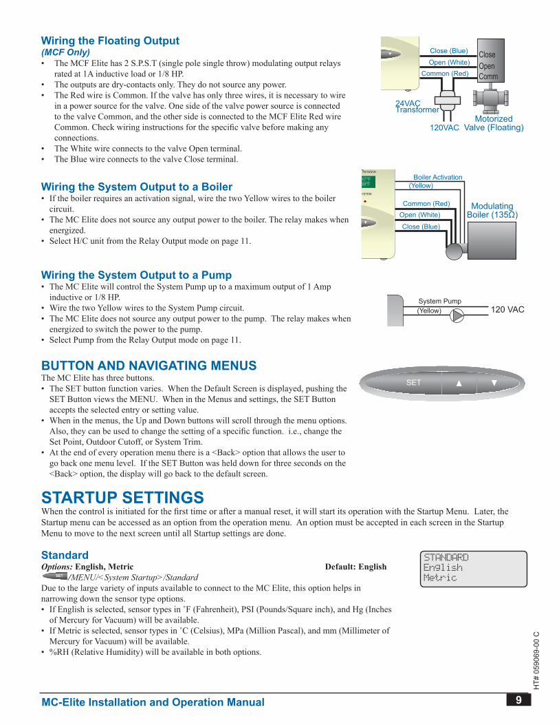
Wiring the Floating output(MCF Only)• The MCF Elite has 2 S.P.S.T (single pole single throw) modulating output relays
rated at 1A inductive load or 1/8 HP.• The outputs are dry-contacts only. They do not source any power.• The Red wire is Common. If the valve has only three wires, it is necessary to wire
in a power source for the valve. One side of the valve power source is connected to the valve Common, and the other side is connected to the MCF Elite Red wire Common. Check wiring instructions for the specific valve before making any connections.
• The White wire connects to the valve Open terminal.• The Blue wire connects to the valve Close terminal.
MotorizedValve 4-20mA
Common (Red)
4-20mA (White)
Not Used (Blue)
+ --+
30-36VDCExcitationVoltage
120 VAC
System Pump
Power (Black)
(Yellow) 120 VAC
MCA Modulating a 4-20mA Actuator
MotorizedValve (Voltage)
Common (Red)
Voltage (Blue)
Not Used (White)
-+
120 VAC
System Pump
Power (Black)
(Yellow) 120 VAC
MCA Modulating a Voltage Actuator
Common (Red)
4-20mA (White)
Not Used (Blue)
30-36VDCExcitationVoltage Modulating
Boiler 4-20mA
- +
120 VAC
System Pump
Power (Black)
(Yellow) 120 VAC
MCA Modulating a 4-20mA Boiler
Common (Red)
Voltage (Blue)
Not Used (White) ModulatingBoiler (Voltage)
-+
120 VAC
System Pump
Power (Black)
(Yellow) 120 VAC
MCA Modulating a Voltage Boiler
120 VACBoiler Activation
Power (Black)
(Yellow)
Common (Red)
Close (Blue)
Open (White)Modulating
Boiler (135Ω)
MCP Modulating a 135Ω Boiler
120 VAC
System Pump
MotorizedValve (Floating)
Power (Black)
(Yellow)
Common (Red)
Close (Blue)
Open (White)CloseOpenComm
24VACTransformer
120VAC
120 VAC
MCF Modulating a Floating Actuator
+ -
SystemDecrease
®
SYSTEM = 147oF
TARGET = 150oF
DECREASE SYSTEMINCREASE SystemDecrease
®
SYSTEM = 147oF
TARGET = 150oF
DECREASE SYSTEMINCREASE
SystemDecrease
®
SYSTEM = 147oF
TARGET = 150oF
DECREASE SYSTEMINCREASE SystemDecrease
®
SYSTEM = 147oF
TARGET = 150oF
DECREASE SYSTEMINCREASE
SystemDecrease
®
SYSTEM = 147oF
TARGET = 150oF
DECREASE SYSTEMINCREASE SystemDecrease
®
SYSTEM = 147oF
TARGET = 150oF
DECREASE SYSTEMINCREASE
Wiring the System Output to a boiler• If the boiler requires an activation signal, wire the two Yellow wires to the boiler
circuit.• The MC Elite does not source any output power to the boiler. The relay makes when
energized.• Select H/C unit from the Relay Output mode on page 11.
MotorizedValve 4-20mA
Common (Red)
4-20mA (White)
Not Used (Blue)
+ --+
30-36VDCExcitationVoltage
120 VAC
System Pump
Power (Black)
(Yellow) 120 VAC
MCA Modulating a 4-20mA Actuator
MotorizedValve (Voltage)
Common (Red)
Voltage (Blue)
Not Used (White)
-+
120 VAC
System Pump
Power (Black)
(Yellow) 120 VAC
MCA Modulating a Voltage Actuator
Common (Red)
4-20mA (White)
Not Used (Blue)
30-36VDCExcitationVoltage Modulating
Boiler 4-20mA
- +
120 VAC
System Pump
Power (Black)
(Yellow) 120 VAC
MCA Modulating a 4-20mA Boiler
Common (Red)
Voltage (Blue)
Not Used (White) ModulatingBoiler (Voltage)
-+
120 VAC
System Pump
Power (Black)
(Yellow) 120 VAC
MCA Modulating a Voltage Boiler
120 VACBoiler Activation
Power (Black)
(Yellow)
Common (Red)
Close (Blue)
Open (White)Modulating
Boiler (135Ω)
MCP Modulating a 135Ω Boiler
120 VAC
System Pump
MotorizedValve (Floating)
Power (Black)
(Yellow)
Common (Red)
Close (Blue)
Open (White)CloseOpenComm
24VACTransformer
120VAC
120 VAC
MCF Modulating a Floating Actuator
+ -
SystemDecrease
®
SYSTEM = 147oF
TARGET = 150oF
DECREASE SYSTEMINCREASE SystemDecrease
®
SYSTEM = 147oF
TARGET = 150oF
DECREASE SYSTEMINCREASE
SystemDecrease
®
SYSTEM = 147oF
TARGET = 150oF
DECREASE SYSTEMINCREASE SystemDecrease
®
SYSTEM = 147oF
TARGET = 150oF
DECREASE SYSTEMINCREASE
SystemDecrease
®
SYSTEM = 147oF
TARGET = 150oF
DECREASE SYSTEMINCREASE SystemDecrease
®
SYSTEM = 147oF
TARGET = 150oF
DECREASE SYSTEMINCREASE
Wiring the System Output to a Pump• The MC Elite will control the System Pump up to a maximum output of 1 Amp
inductive or 1/8 HP.• Wire the two Yellow wires to the System Pump circuit.• The MC Elite does not source any output power to the pump. The relay makes when
energized to switch the power to the pump.• Select Pump from the Relay Output mode on page 11.
BoilerSYS
PumpDHWPump
SET
®
C O R P O R A T I O N
R
SYSTEM = 147F
TARGET = 150F
MotorizedValve 4-20mA
Common (Red)
4-20mA (White)
Not Used (Blue)
+ --+
30-36VDCExcitationVoltage
120 VAC
System Pump
Power (Black)
(Yellow) 120 VAC
MCA Modulating a 4-20mA Actuator
DECREASE SYSTEMINCREASEBoilerSYS
PumpDHWPump
SET
®
C O R P O R A T I O N
R
SYSTEM = 147F
TARGET = 150F
MotorizedValve (Voltage)
Common (Red)
Voltage (Blue)
Not Used (White)
-+
120 VAC
System Pump
Power (Black)
(Yellow) 120 VAC
MCA Modulating a Voltage Actuator
DECREASE SYSTEMINCREASE
BoilerSYS
PumpDHWPump
SET
®
C O R P O R A T I O N
R
SYSTEM = 147F
TARGET = 150F
Common (Red)
4-20mA (White)
Not Used (Blue)
30-36VDCExcitationVoltage Modulating
Boiler 4-20mA
- +
120 VAC
System Pump
Power (Black)
(Yellow) 120 VAC
MCA Modulating a 4-20mA Boiler
DECREASE SYSTEMINCREASEBoilerSYS
PumpDHWPump
SET
®
C O R P O R A T I O N
R
SYSTEM = 147F
TARGET = 150F
Common (Red)
Voltage (Blue)
Not Used (White) ModulatingBoiler (Voltage)
-+
120 VAC
System Pump
Power (Black)
(Yellow) 120 VAC
MCA Modulating a Voltage Boiler
DECREASE SYSTEMINCREASE
BoilerSYS
PumpDHWPump
SET
®
C O R P O R A T I O N
R
SYSTEM = 147F
TARGET = 150F
120 VACBoiler Activation
Power (Black)
(Yellow)
Common (Red)
Close (Blue)
Open (White)Modulating
Boiler (135Ω)
MCP Modulating a 135Ω Boiler
DECREASE SYSTEMINCREASEBoiler
SYSPump
DHWPump
SET
®
C O R P O R A T I O N
R
SYSTEM = 147F
TARGET = 150F
120 VAC
System Pump
MotorizedValve (Floating)
Power (Black)
(Yellow)
Common (Red)
Close (Blue)
Open (White)CloseOpenComm
24VACTransformer
120VAC
120 VAC
MCF Modulating a Floating Actuator
CLOSE SYSTEMOPEN
+ -
bUTTON AND NAvIgATINg MENUSThe MC Elite has three buttons.• The SET button function varies. When the Default Screen is displayed, pushing the
SET Button views the MENU. When in the Menus and settings, the SET Button accepts the selected entry or setting value.
• When in the menus, the Up and Down buttons will scroll through the menu options. Also, they can be used to change the setting of a specific function. i.e., change the Set Point, Outdoor Cutoff, or System Trim.
• At the end of every operation menu there is a <Back> option that allows the user to go back one menu level. If the SET Button was held down for three seconds on the <Back> option, the display will go back to the default screen.
SET
SET
SET
SET
SET SET
STARTUP SETTINgSWhen the control is initiated for the first time or after a manual reset, it will start its operation with the Startup Menu. Later, the Startup menu can be accessed as an option from the operation menu. An option must be accepted in each screen in the Startup Menu to move to the next screen until all Startup settings are done.
StandardOptions: English, Metric Default: English
SET
SET
SET
SET
SET SET /MENU/<System Startup>/StandardDue to the large variety of inputs available to connect to the MC Elite, this option helps in narrowing down the sensor type options. • If English is selected, sensor types in ˚F (Fahrenheit), PSI (Pounds/Square inch), and Hg (Inches
of Mercury for Vacuum) will be available.• If Metric is selected, sensor types in ˚C (Celsius), MPa (Million Pascal), and mm (Millimeter of
Mercury for Vacuum) will be available.• %RH (Relative Humidity) will be available in both options.
STANDARD
English
Metric
10 MC-Elite Installation and Operation Manual
HT#
059
069-
00 C
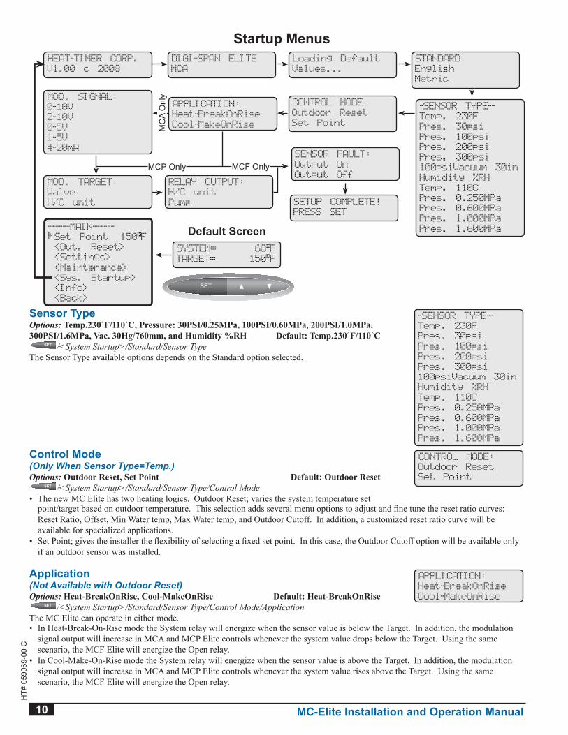
Sensor TypeOptions: Temp.230˚F/110˚C, Pressure: 30PSI/0.25MPa, 100PSI/0.60MPa, 200PSI/1.0MPa, 300PSI/1.6MPa, Vac. 30Hg/760mm, and Humidity %RH Default: Temp.230˚F/110˚C
SET
SET
SET
SET
SET SET /<System Startup>/Standard/Sensor TypeThe Sensor Type available options depends on the Standard option selected.
-SENSOR TYPE--
Temp. 230F
Pres. 30psi
Pres. 100psi
Pres. 200psi
Pres. 300psi
100psiVacuum 30in
Humidity %RH
Temp. 110C
Pres. 0.250MPa
Pres. 0.600MPa
Pres. 1.000MPa
Pres. 1.600MPa
Control Mode(Only When Sensor Type=Temp.)Options: Outdoor Reset, Set Point Default: Outdoor Reset
SET
SET
SET
SET
SET SET /<System Startup>/Standard/Sensor Type/Control Mode• The new MC Elite has two heating logics. Outdoor Reset; varies the system temperature set
CONTROL MODE:
Outdoor Reset
Set Point
point/target based on outdoor temperature. This selection adds several menu options to adjust and fine tune the reset ratio curves: Reset Ratio, Offset, Min Water temp, Max Water temp, and Outdoor Cutoff. In addition, a customized reset ratio curve will be available for specialized applications.
• Set Point; gives the installer the flexibility of selecting a fixed set point. In this case, the Outdoor Cutoff option will be available only if an outdoor sensor was installed.
Application(Not Available with Outdoor Reset)Options: Heat-BreakOnRise, Cool-MakeOnRise Default: Heat-BreakOnRise
SET
SET
SET
SET
SET SET /<System Startup>/Standard/Sensor Type/Control Mode/ApplicationThe MC Elite can operate in either mode.
APPLICATION:
Heat-BreakOnRise
Cool-MakeOnRise
• In Heat-Break-On-Rise mode the System relay will energize when the sensor value is below the Target. In addition, the modulation signal output will increase in MCA and MCP Elite controls whenever the system value drops below the Target. Using the same scenario, the MCF Elite will energize the Open relay.
• In Cool-Make-On-Rise mode the System relay will energize when the sensor value is above the Target. In addition, the modulation signal output will increase in MCA and MCP Elite controls whenever the system value rises above the Target. Using the same scenario, the MCF Elite will energize the Open relay.
HEAT-TIMER CORP.
V1.00 c 2008
DIGI-SPAN ELITE
MCA
Loading Default
Values...
STANDARD
English
Metric
SENSOR FAULT:
Output On
Output Off
SETUP COMPLETE!
PRESS SET
Startup Menus
SYSTEM= 68 F
TARGET= 150 F
SET
SET
SET
SET
SET SET
CONTROL MODE:
Outdoor Reset
Set Point
-SENSOR TYPE--
Temp. 230F
Pres. 30psi
Pres. 100psi
Pres. 200psi
Pres. 300psi
100psiVacuum 30in
Humidity %RH
Temp. 110C
Pres. 0.250MPa
Pres. 0.600MPa
Pres. 1.000MPa
Pres. 1.600MPaDefault Screen
APPLICATION:
Heat-BreakOnRise
Cool-MakeOnRise
MOD. SIGNAL:
0-10V
2-10V
0-5V
1-5V
4-20mA
MOD. TARGET:
Valve
H/C unit
RELAY OUTPUT:
H/C unit
Pump
MCF Only
------MAIN------
Set Point 150 F
<Out. Reset>
<Settings>
<Maintenance>
<Sys. Startup>
<Info>
<Back>
MCP OnlyM
CA
Onl
y
MC-Elite Installation and Operation Manual 11
HT#
059
069-
00 C
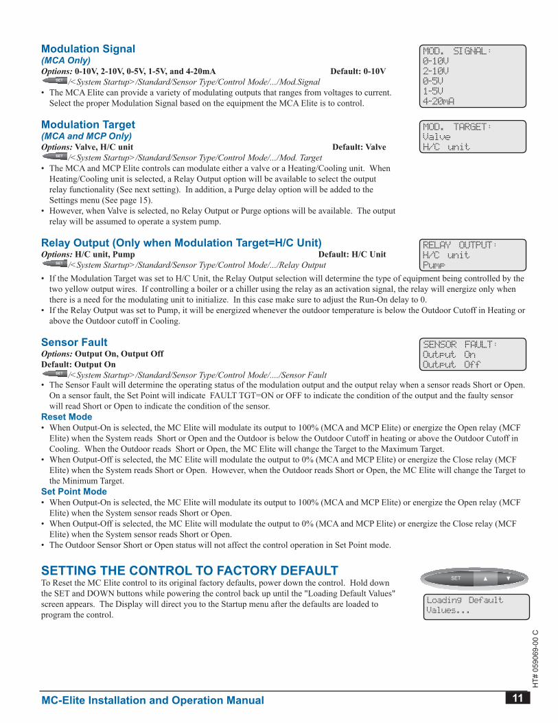
Modulation Signal(MCA Only)Options: 0-10V, 2-10V, 0-5V, 1-5V, and 4-20mA Default: 0-10V
SET
SET
SET
SET
SET SET /<System Startup>/Standard/Sensor Type/Control Mode/.../Mod.Signal• The MCA Elite can provide a variety of modulating outputs that ranges from voltages to current.
Select the proper Modulation Signal based on the equipment the MCA Elite is to control.
MOD. SIGNAL:
0-10V
2-10V
0-5V
1-5V
4-20mA
Modulation Target(MCA and MCP Only)Options: Valve, H/C unit Default: Valve
SET
SET
SET
SET
SET SET /<System Startup>/Standard/Sensor Type/Control Mode/.../Mod. Target• The MCA and MCP Elite controls can modulate either a valve or a Heating/Cooling unit. When
Heating/Cooling unit is selected, a Relay Output option will be available to select the output relay functionality (See next setting). In addition, a Purge delay option will be added to the Settings menu (See page 15).
• However, when Valve is selected, no Relay Output or Purge options will be available. The output relay will be assumed to operate a system pump.
MOD. TARGET:
Valve
H/C unit
Relay Output (Only when Modulation Target=H/C Unit)Options: H/C unit, Pump Default: H/C Unit
SET
SET
SET
SET
SET SET /<System Startup>/Standard/Sensor Type/Control Mode/.../Relay Output
RELAY OUTPUT:
H/C unit
Pump
• If the Modulation Target was set to H/C Unit, the Relay Output selection will determine the type of equipment being controlled by the two yellow output wires. If controlling a boiler or a chiller using the relay as an activation signal, the relay will energize only when there is a need for the modulating unit to initialize. In this case make sure to adjust the Run-On delay to 0.
• If the Relay Output was set to Pump, it will be energized whenever the outdoor temperature is below the Outdoor Cutoff in Heating or above the Outdoor cutoff in Cooling.
sensor FaultOptions: Output On, Output Off Default: Output On
SET
SET
SET
SET
SET SET /<System Startup>/Standard/Sensor Type/Control Mode/..../Sensor Fault
SENSOR FAULT:
Output On
Output Off
• The Sensor Fault will determine the operating status of the modulation output and the output relay when a sensor reads Short or Open. On a sensor fault, the Set Point will indicate FAULT TGT=ON or OFF to indicate the condition of the output and the faulty sensor will read Short or Open to indicate the condition of the sensor.
Reset Mode• When Output-On is selected, the MC Elite will modulate its output to 100% (MCA and MCP Elite) or energize the Open relay (MCF
Elite) when the System reads Short or Open and the Outdoor is below the Outdoor Cutoff in heating or above the Outdoor Cutoff in Cooling. When the Outdoor reads Short or Open, the MC Elite will change the Target to the Maximum Target.
• When Output-Off is selected, the MC Elite will modulate the output to 0% (MCA and MCP Elite) or energize the Close relay (MCF Elite) when the System reads Short or Open. However, when the Outdoor reads Short or Open, the MC Elite will change the Target to the Minimum Target.
Set Point Mode• When Output-On is selected, the MC Elite will modulate its output to 100% (MCA and MCP Elite) or energize the Open relay (MCF
Elite) when the System sensor reads Short or Open.• When Output-Off is selected, the MC Elite will modulate the output to 0% (MCA and MCP Elite) or energize the Close relay (MCF
Elite) when the System sensor reads Short or Open.• The Outdoor Sensor Short or Open status will not affect the control operation in Set Point mode.
setting tHe Control to FaCtory deFaultTo Reset the MC Elite control to its original factory defaults, power down the control. Hold down the SET and DOWN buttons while powering the control back up until the "Loading Default Values" screen appears. The Display will direct you to the Startup menu after the defaults are loaded to program the control.
SET
SET
SET
SET
SET SET
Loading Default
Values...
12 MC-Elite Installation and Operation Manual
HT#
059
069-
00 C
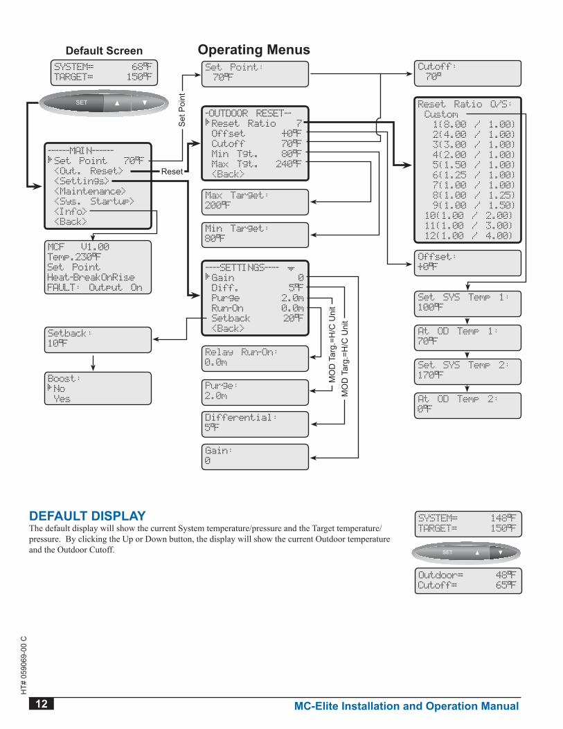
deFault disPlayThe default display will show the current System temperature/pressure and the Target temperature/pressure. By clicking the Up or Down button, the display will show the current Outdoor temperature and the Outdoor Cutoff.
SYSTEM= 148 F
TARGET= 150 F
SET
SET
SET
SET
SET SET
Outdoor= 48 F
Cutoff= 65 F
------MAIN------
Set Point 70 F
<Out. Reset>
<Settings>
<Maintenance>
<Sys. Startup>
<Info>
<Back>
Set Point:
70 F
----SETTINGS----
Gain 0
Diff. 5 F
Purge 2.0m
Run-On 0.0m
Setback 20 F
<Back>
Gain:
0
MCF V1.00
Temp.230 F
Set Point
Heat-BreakOnRise
FAULT: Output On
Operating Menus
Set SYS Temp 1:
100 F
-OUTDOOR RESET--
Reset Ratio 7
Offset +0 F
Cutoff 70 F
Min Tgt. 80 F
Max Tgt. 240 F
<Back>
Cutoff:
70
Reset Ratio O/S:
Custom
1(8.00 / 1.00)
2(4.00 / 1.00)
3(3.00 / 1.00)
4(2.00 / 1.00)
5(1.50 / 1.00)
6(1.25 / 1.00)
7(1.00 / 1.00)
8(1.00 / 1.25)
9(1.00 / 1.50)
10(1.00 / 2.00)
11(1.00 / 3.00)
12(1.00 / 4.00)
At OD Temp 1:
70 F
Set SYS Temp 2:
170 F
At OD Temp 2:
0 F
Offset:
+0 F
Min Target:
80 F
Max Target:
200 F
Purge:
2.0m
Setback:
10 F
Boost:
No
Yes
Set
Poi
ntReset
MO
D T
arg
=H/C
Uni
t
SYSTEM= 68 F
TARGET= 150 F
SET
SET
SET
SET
SET SET
Default Screen
Relay Run-On:
0.0m
MO
D T
arg
=H/C
Uni
t
Differential:
5 F
MC-Elite Installation and Operation Manual 13
HT#
059
069-
00 C
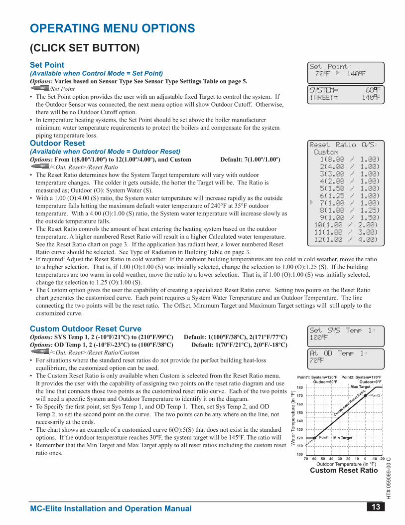
OPERATINg MENU OPTIONS(CLICK SET bUTTON)Set Point(Available when Control Mode = Set Point)Options: Varies based on Sensor Type See Sensor Type Settings Table on page 5.
SET
SET
SET
SET
SET SET /Set Point• The Set Point option provides the user with an adjustable fixed Target to control the system. If
the Outdoor Sensor was connected, the next menu option will show Outdoor Cutoff. Otherwise, there will be no Outdoor Cutoff option.
• In temperature heating systems, the Set Point should be set above the boiler manufacturer minimum water temperature requirements to protect the boilers and compensate for the system piping temperature loss.
Set Point:
70 F 140 F
SYSTEM= 68 F
TARGET= 140 F
Outdoor Reset(Available when Control Mode = Outdoor Reset)Options: From 1(8.00º/1.00º) to 12(1.00º/4.00º), and Custom Default: 7(1.00º/1.00º)
SET
SET
SET
SET
SET SET /<Out. Reset>/Reset Ratio• The Reset Ratio determines how the System Target temperature will vary with outdoor
temperature changes. The colder it gets outside, the hotter the Target will be. The Ratio is measured as; Outdoor (O): System Water (S).
• With a 1.00 (O):4.00 (S) ratio, the System water temperature will increase rapidly as the outside temperature falls hitting the maximum default water temperature of 240°F at 35°F outdoor temperature. With a 4.00 (O):1.00 (S) ratio, the System water temperature will increase slowly as the outside temperature falls.
• The Reset Ratio controls the amount of heat entering the heating system based on the outdoor temperature. A higher numbered Reset Ratio will result in a higher Calculated water temperature. See the Reset Ratio chart on page 3. If the application has radiant heat, a lower numbered Reset Ratio curve should be selected. See Type of Radiation in Building Table on page 3.
Reset Ratio O/S:
Custom
1(8.00 / 1.00)
2(4.00 / 1.00)
3(3.00 / 1.00)
4(2.00 / 1.00)
5(1.50 / 1.00)
6(1.25 / 1.00)
7(1.00 / 1.00)
8(1.00 / 1.25)
9(1.00 / 1.50)
10(1.00 / 2.00)
11(1.00 / 3.00)
12(1.00 / 4.00)
• If required: Adjust the Reset Ratio in cold weather. If the ambient building temperatures are too cold in cold weather, move the ratio to a higher selection. That is, if 1.00 (O):1.00 (S) was initially selected, change the selection to 1.00 (O):1.25 (S). If the building temperatures are too warm in cold weather, move the ratio to a lower selection. That is, if 1.00 (O):1.00 (S) was initially selected, change the selection to 1.25 (O):1.00 (S).
• The Custom option gives the user the capability of creating a specialized Reset Ratio curve. Setting two points on the Reset Ratio chart generates the customized curve. Each point requires a System Water Temperature and an Outdoor Temperature. The line connecting the two points will be the reset ratio. The Offset, Minimum Target and Maximum Target settings will still apply to the customized curve.
Custom Outdoor Reset CurveOptions: SYS Temp 1, 2 (-10ºF/21ºC) to (210ºF/99ºC) Default: 1(100ºF/38ºC), 2(171ºF/77ºC)Options: OD Temp 1, 2 (-10ºF/-23ºC) to (100ºF/38ºC) Default: 1(70ºF/21ºC), 2(0ºF/-18ºC)
SET
SET
SET
SET
SET SET /<Out. Reset>/Reset Ratio/Custom• For situations where the standard reset ratios do not provide the perfect building heat-loss
equilibrium, the customized option can be used.• The Custom Reset Ratio is only available when Custom is selected from the Reset Ratio menu.
It provides the user with the capability of assigning two points on the reset ratio diagram and use the line that connects those two points as the customized reset ratio curve. Each of the two points will need a specific System and Outdoor Temperature to identify it on the diagram.
• To Specify the first point, set Sys Temp 1, and OD Temp 1. Then, set Sys Temp 2, and OD Temp 2, to set the second point on the curve. The two points can be any where on the line, not necessarily at the ends.
• The chart shows an example of a customized curve 6(O):5(S) that does not exist in the standard options. If the outdoor temperature reaches 30ºF, the system target will be 145ºF. The ratio will
• Remember that the Min Target and Max Target apply to all reset ratios including the custom reset ratio ones.
Set SYS Temp 1:
100 F
At OD Temp 1:
70 F
Outdoor Temperature (in °F)70 60 50 40 2030 0 -1010 -20
120
140
130
150
160
170
180
100
110Wat
er T
empe
ratu
re (i
n °F
)
Custom Reset Ratio
Point1: System=120°FOudoor=60°F
Point2: System=170°FOudoor=0°F
Point1
Point2
Customized Reset R
atioMax Target
Min Target
Outdoor Temperature (in °F)70 60 50 40 2030 0 -1010 -20
120
140
130
150
160
170
180
100
110Wat
er T
empe
ratu
re (i
n °F
)
Target Offset
Offset=10°FReset Ratio=1.5 : 1.0
Reset Ratio
Max Target
Min Target
Reset Ratio + 10F Offset
Min Target=120°FMax Target=170°F
14 MC-Elite Installation and Operation Manual
HT#
059
069-
00 C
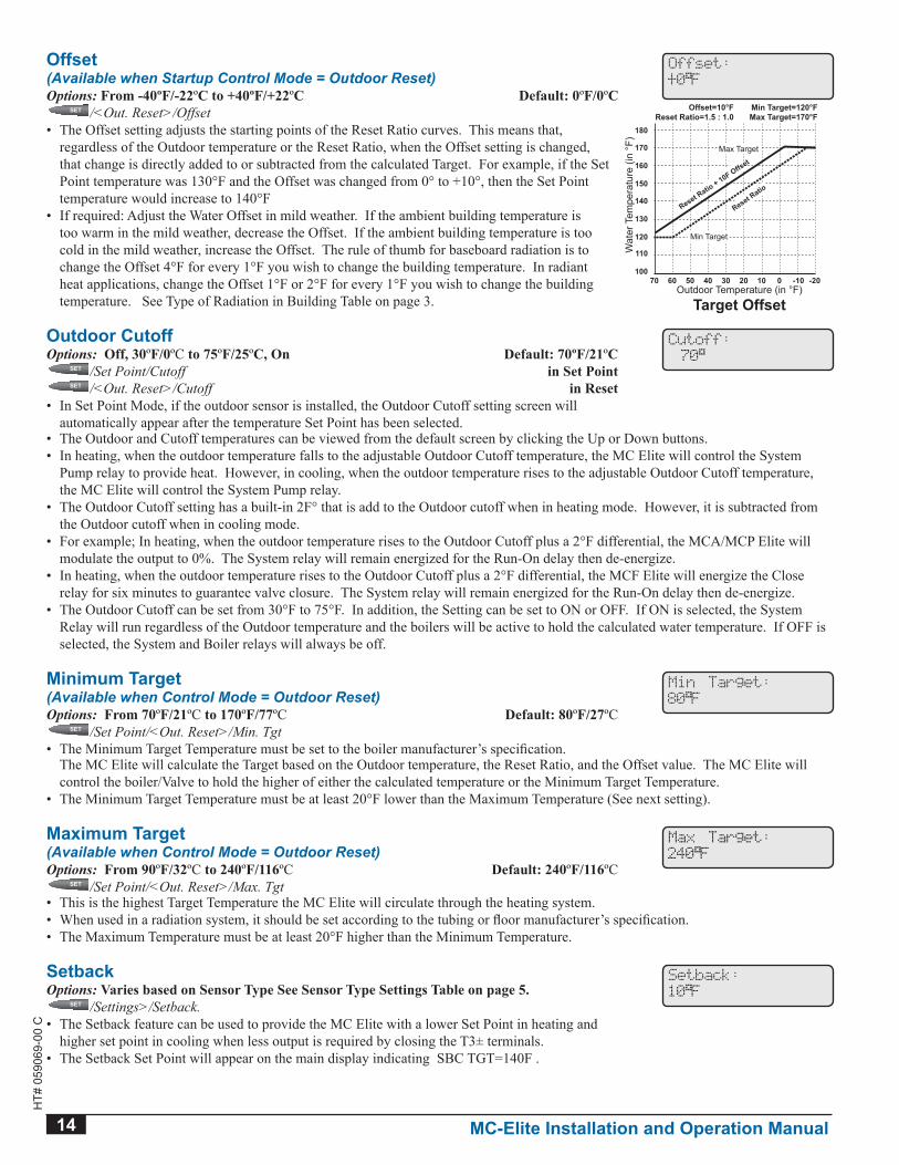
Offset(Available when Startup Control Mode = Outdoor Reset)Options: From -40ºF/-22ºC to +40ºF/+22ºC Default: 0ºF/0ºC
SET
SET
SET
SET
SET SET /<Out. Reset>/Offset• The Offset setting adjusts the starting points of the Reset Ratio curves. This means that,
regardless of the Outdoor temperature or the Reset Ratio, when the Offset setting is changed, that change is directly added to or subtracted from the calculated Target. For example, if the Set Point temperature was 130°F and the Offset was changed from 0° to +10°, then the Set Point temperature would increase to 140°F
• If required: Adjust the Water Offset in mild weather. If the ambient building temperature is too warm in the mild weather, decrease the Offset. If the ambient building temperature is too cold in the mild weather, increase the Offset. The rule of thumb for baseboard radiation is to change the Offset 4°F for every 1°F you wish to change the building temperature. In radiant heat applications, change the Offset 1°F or 2°F for every 1°F you wish to change the building temperature. See Type of Radiation in Building Table on page 3.
Offset:
+0 F
Outdoor Temperature (in °F)70 60 50 40 2030 0 -1010 -20
120
140
130
150
160
170
180
100
110Wat
er T
empe
ratu
re (i
n °F
)
Custom Reset Ratio
Point1: System=120°FOudoor=60°F
Point2: System=170°FOudoor=0°F
Point1
Point2
Customized Reset R
atioMax Target
Min Target
Outdoor Temperature (in °F)70 60 50 40 2030 0 -1010 -20
120
140
130
150
160
170
180
100
110Wat
er T
empe
ratu
re (i
n °F
)
Target Offset
Offset=10°FReset Ratio=1.5 : 1.0
Reset Ratio
Max Target
Min Target
Reset Ratio + 10F Offset
Min Target=120°FMax Target=170°F
Outdoor CutoffOptions: Off, 30ºF/0ºC to 75ºF/25ºC, On Default: 70ºF/21ºC
SET
SET
SET
SET
SET SET /Set Point/Cutoff in Set Point
SET
SET
SET
SET
SET SET /<Out. Reset>/Cutoff in Reset• In Set Point Mode, if the outdoor sensor is installed, the Outdoor Cutoff setting screen will
automatically appear after the temperature Set Point has been selected.
Cutoff:
70
• The Outdoor and Cutoff temperatures can be viewed from the default screen by clicking the Up or Down buttons.• In heating, when the outdoor temperature falls to the adjustable Outdoor Cutoff temperature, the MC Elite will control the System
Pump relay to provide heat. However, in cooling, when the outdoor temperature rises to the adjustable Outdoor Cutoff temperature, the MC Elite will control the System Pump relay.
• The Outdoor Cutoff setting has a built-in 2F° that is add to the Outdoor cutoff when in heating mode. However, it is subtracted from the Outdoor cutoff when in cooling mode.
• For example; In heating, when the outdoor temperature rises to the Outdoor Cutoff plus a 2°F differential, the MCA/MCP Elite will modulate the output to 0%. The System relay will remain energized for the Run-On delay then de-energize.
• In heating, when the outdoor temperature rises to the Outdoor Cutoff plus a 2°F differential, the MCF Elite will energize the Close relay for six minutes to guarantee valve closure. The System relay will remain energized for the Run-On delay then de-energize.
• The Outdoor Cutoff can be set from 30°F to 75°F. In addition, the Setting can be set to ON or OFF. If ON is selected, the System Relay will run regardless of the Outdoor temperature and the boilers will be active to hold the calculated water temperature. If OFF is selected, the System and Boiler relays will always be off.
Minimum Target(Available when Control Mode = Outdoor Reset)Options: From 70ºF/21ºC to 170ºF/77ºC Default: 80ºF/27ºC
SET
SET
SET
SET
SET SET /Set Point/<Out. Reset>/Min. Tgt• The Minimum Target Temperature must be set to the boiler manufacturer’s specification.
Min Target:
80 F
The MC Elite will calculate the Target based on the Outdoor temperature, the Reset Ratio, and the Offset value. The MC Elite will control the boiler/Valve to hold the higher of either the calculated temperature or the Minimum Target Temperature.
• The Minimum Target Temperature must be at least 20°F lower than the Maximum Temperature (See next setting).
Maximum Target(Available when Control Mode = Outdoor Reset)Options: From 90ºF/32ºC to 240ºF/116ºC Default: 240ºF/116ºC
SET
SET
SET
SET
SET SET /Set Point/<Out. Reset>/Max. Tgt
Max Target:
240 F
• This is the highest Target Temperature the MC Elite will circulate through the heating system.• When used in a radiation system, it should be set according to the tubing or floor manufacturer’s specification.• The Maximum Temperature must be at least 20°F higher than the Minimum Temperature.
SetbackOptions: Varies based on Sensor Type See Sensor Type Settings Table on page 5.
SET
SET
SET
SET
SET SET /Settings>/Setback.• The Setback feature can be used to provide the MC Elite with a lower Set Point in heating and
higher set point in cooling when less output is required by closing the T3± terminals.• The Setback Set Point will appear on the main display indicating SBC TGT=140F .
Setback:
10 F
MC-Elite Installation and Operation Manual 15
HT#
059
069-
00 C
• For example; in heating, when the calculated temperature is 160°F and the Setback is set to 20°F, a setback call will change the Set Point to (160°F - 20°F) 140°F.
• A typical use for the Setback is to provide a reduced system temperature to a building during the night or on the weekends when building is not occupied, but heat is still required.
• The Setback is activated by closing/shorting the T3± terminals using an external timer, control, or a switch.
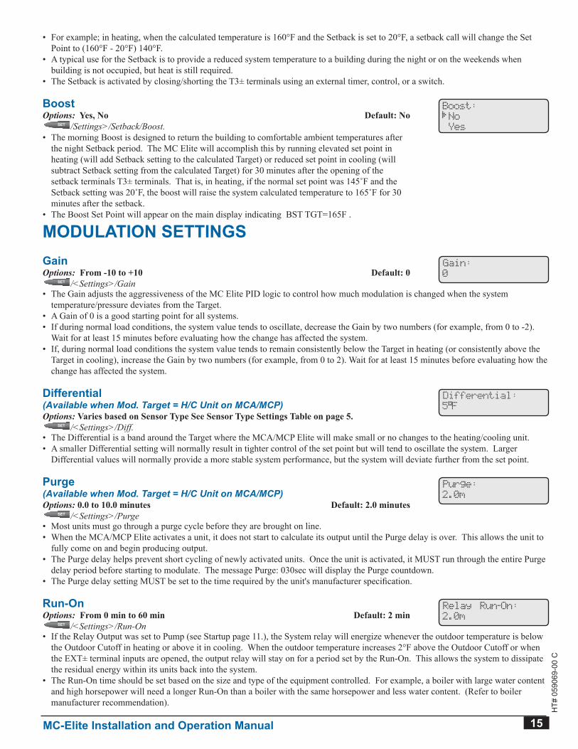
boostOptions: Yes, No Default: No
SET
SET
SET
SET
SET SET /Settings>/Setback/Boost.• The morning Boost is designed to return the building to comfortable ambient temperatures after
the night Setback period. The MC Elite will accomplish this by running elevated set point in heating (will add Setback setting to the calculated Target) or reduced set point in cooling (will subtract Setback setting from the calculated Target) for 30 minutes after the opening of the setback terminals T3± terminals. That is, in heating, if the normal set point was 145˚F and the Setback setting was 20˚F, the boost will raise the system calculated temperature to 165˚F for 30 minutes after the setback.
• The Boost Set Point will appear on the main display indicating BST TGT=165F .
Boost:
No
Yes
MODULATION SETTINgSgainOptions: From -10 to +10 Default: 0
SET
SET
SET
SET
SET SET /<Settings>/Gain
Gain:
0
• The Gain adjusts the aggressiveness of the MC Elite PID logic to control how much modulation is changed when the system temperature/pressure deviates from the Target.
• A Gain of 0 is a good starting point for all systems.• If during normal load conditions, the system value tends to oscillate, decrease the Gain by two numbers (for example, from 0 to -2).
Wait for at least 15 minutes before evaluating how the change has affected the system.• If, during normal load conditions the system value tends to remain consistently below the Target in heating (or consistently above the
Target in cooling), increase the Gain by two numbers (for example, from 0 to 2). Wait for at least 15 minutes before evaluating how the change has affected the system.
Differential(Available when Mod. Target = H/C Unit on MCA/MCP)Options: Varies based on Sensor Type See Sensor Type Settings Table on page 5.
SET
SET
SET
SET
SET SET /<Settings>/Diff.
Differential:
5 F
• The Differential is a band around the Target where the MCA/MCP Elite will make small or no changes to the heating/cooling unit.• A smaller Differential setting will normally result in tighter control of the set point but will tend to oscillate the system. Larger
Differential values will normally provide a more stable system performance, but the system will deviate further from the set point.
Purge(Available when Mod. Target = H/C Unit on MCA/MCP)Options: 0.0 to 10.0 minutes Default: 2.0 minutes
SET
SET
SET
SET
SET SET /<Settings>/Purge
Purge:
2.0m
• Most units must go through a purge cycle before they are brought on line.• When the MCA/MCP Elite activates a unit, it does not start to calculate its output until the Purge delay is over. This allows the unit to
fully come on and begin producing output.• The Purge delay helps prevent short cycling of newly activated units. Once the unit is activated, it MUST run through the entire Purge
delay period before starting to modulate. The message Purge: 030sec will display the Purge countdown.• The Purge delay setting MUST be set to the time required by the unit's manufacturer specification.
Run-OnOptions: From 0 min to 60 min Default: 2 min
SET
SET
SET
SET
SET SET /<Settings>/Run-On
Relay Run-On:
2.0m
• If the Relay Output was set to Pump (see Startup page 11.), the System relay will energize whenever the outdoor temperature is below the Outdoor Cutoff in heating or above it in cooling. When the outdoor temperature increases 2°F above the Outdoor Cutoff or when the EXT± terminal inputs are opened, the output relay will stay on for a period set by the Run-On. This allows the system to dissipate the residual energy within its units back into the system.
• The Run-On time should be set based on the size and type of the equipment controlled. For example, a boiler with large water content and high horsepower will need a longer Run-On than a boiler with the same horsepower and less water content. (Refer to boiler manufacturer recommendation).
16 MC-Elite Installation and Operation Manual
HT#
059
069-
00 C
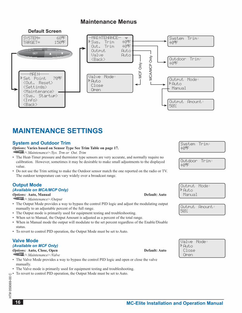
MAINTENANCE SETTINgSSystem and Outdoor TrimOptions: Varies based on Sensor Type See Trim Table on page 17.
SET
SET
SET
SET
SET SET /<Maintenance>/Sys. Trm or Out. Trim• The Heat-Timer pressure and thermistor type sensors are very accurate, and normally require no
calibration. However, sometimes it may be desirable to make small adjustments to the displayed value.
• Do not use the Trim setting to make the Outdoor sensor match the one reported on the radio or TV. The outdoor temperature can vary widely over a broadcast range.
System Trim:
+0 F
Outdoor Trim:
+0 F
Output Mode(Available on MCA/MCP Only)Options: Auto, Manual Default: Auto
SET
SET
SET
SET
SET SET /<Maintenance>/Output• The Output Mode provides a way to bypass the control PID logic and adjust the modulating output
manually to an adjustable percent of the full range.• The Output mode is primarily used for equipment testing and troubleshooting.• When set to Manual, the Output Amount is adjusted as a percent of the total range.• When in Manual mode the output will modulate to the set percent regardless of the Enable/Disable
status.• To revert to control PID operation, the Output Mode must be set to Auto.
Output Mode:
Auto
Manual
Output Amount:
50%
valve Mode(Available on MCF Only)Options: Auto, Close, Open Default: Auto
SET
SET
SET
SET
SET SET /<Maintenance>/Valve• The Valve Mode provides a way to bypass the control PID logic and open or close the valve
manually.• The Valve mode is primarily used for equipment testing and troubleshooting.• To revert to control PID operation, the Output Mode must be set to Auto.
Valve Mode:
Auto
Close
Open
System Trim:
+0 F
--MAINTENANCE--
Sys. Trim +0 F
Out. Trim +0 F
Output Auto
Valve Auto
<Back> Outdoor Trim:
+0 F
Output Mode:
Auto
Manual
Valve Mode:
Auto
Close
Open
MC
A/M
CP
Onl
y
MC
F O
nly
------MAIN------
Set Point 70 F
<Out. Reset>
<Settings>
<Maintenance>
<Sys. Startup>
<Info>
<Back>
SYSTEM= 68 F
TARGET= 150 F
SET
SET
SET
SET
SET SET
Default Screen
Maintenance Menus
Output Amount:
50%
MC-Elite Installation and Operation Manual 17
HT#
059
069-
00 C
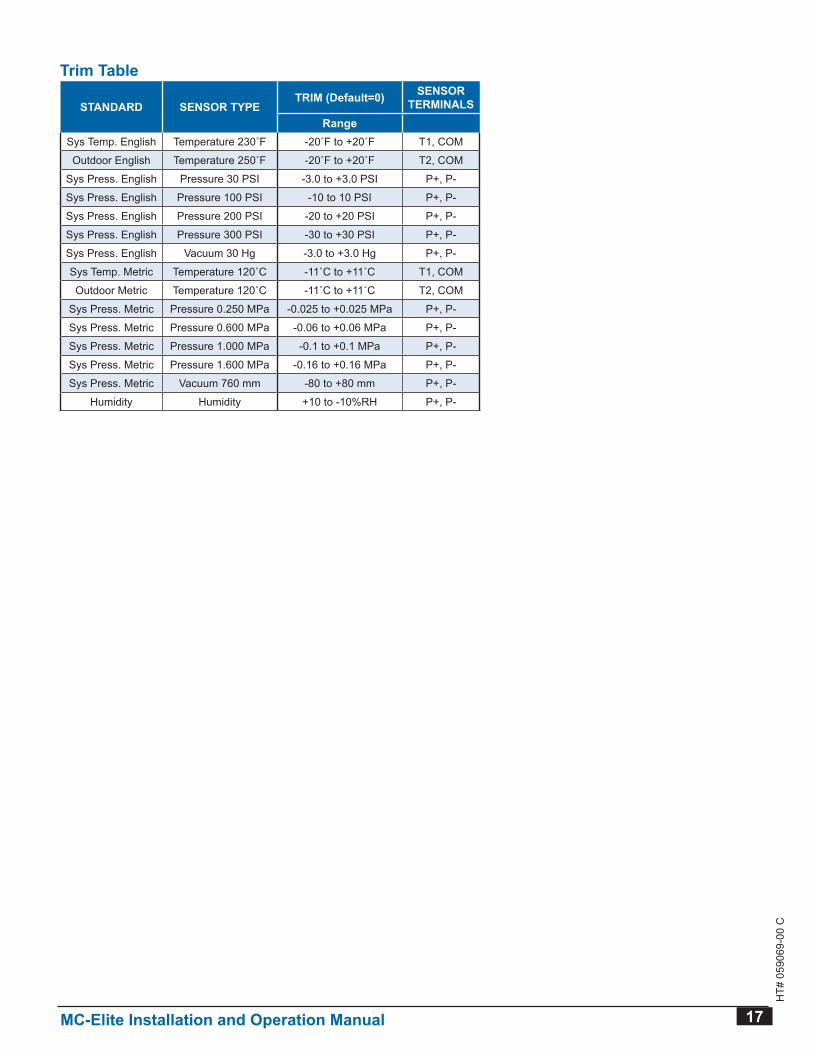
Trim Table
STANDARD sensor tyPeTRIM (Default=0) SENSOR
TERMINALSRange
Sys Temp English Temperature 230˚F -20˚F to +20˚F T1, COM
Outdoor English Temperature 250˚F -20˚F to +20˚F T2, COM
Sys Press English Pressure 30 PSI -3 0 to +3 0 PSI P+, P-
Sys Press English Pressure 100 PSI -10 to 10 PSI P+, P-
Sys Press English Pressure 200 PSI -20 to +20 PSI P+, P-
Sys Press English Pressure 300 PSI -30 to +30 PSI P+, P-
Sys Press English Vacuum 30 Hg -3 0 to +3 0 Hg P+, P-
Sys Temp Metric Temperature 120˚C -11˚C to +11˚C T1, COM
Outdoor Metric Temperature 120˚C -11˚C to +11˚C T2, COM
Sys Press Metric Pressure 0 250 MPa -0 025 to +0 025 MPa P+, P-
Sys Press Metric Pressure 0 600 MPa -0 06 to +0 06 MPa P+, P-
Sys Press Metric Pressure 1 000 MPa -0 1 to +0 1 MPa P+, P-
Sys Press Metric Pressure 1 600 MPa -0 16 to +0 16 MPa P+, P-
Sys Press Metric Vacuum 760 mm -80 to +80 mm P+, P-
Humidity Humidity +10 to -10%RH P+, P-
18 MC-Elite Installation and Operation Manual
HT#
059
069-
00 C
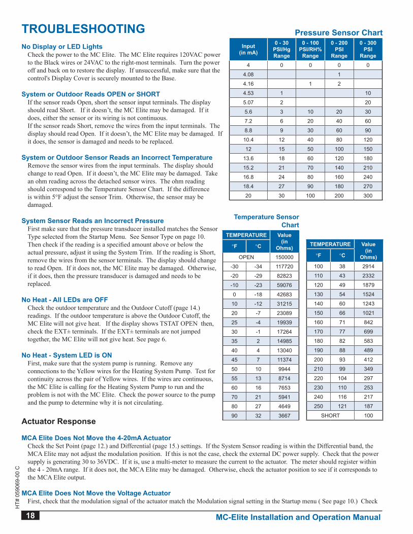
TROUbLESHOOTINgNo Display or LED Lights Check the power to the MC Elite. The MC Elite requires 120VAC power
to the Black wires or 24VAC to the right-most terminals. Turn the power off and back on to restore the display. If unsuccessful, make sure that the control's Display Cover is securely mounted to the Base.
System or Outdoor Reads OPEN or SHORT If the sensor reads Open, short the sensor input terminals. The display
should read Short. If it doesn’t, the MC Elite may be damaged. If it does, either the sensor or its wiring is not continuous.
If the sensor reads Short, remove the wires from the input terminals. The display should read Open. If it doesn’t, the MC Elite may be damaged. If it does, the sensor is damaged and needs to be replaced.
System or Outdoor Sensor Reads an Incorrect Temperature Remove the sensor wires from the input terminals. The display should
change to read Open. If it doesn’t, the MC Elite may be damaged. Take an ohm reading across the detached sensor wires. The ohm reading should correspond to the Temperature Sensor Chart. If the difference is within 5°F adjust the sensor Trim. Otherwise, the sensor may be damaged.
System Sensor Reads an Incorrect Pressure First make sure that the pressure transducer installed matches the Sensor
Type selected from the Startup Menu. See Sensor Type on page 10. Then check if the reading is a specified amount above or below the actual pressure, adjust it using the System Trim. If the reading is Short, remove the wires from the sensor terminals. The display should change to read Open. If it does not, the MC Elite may be damaged. Otherwise, if it does, then the pressure transducer is damaged and needs to be replaced.
no Heat - all leds are oFF Check the outdoor temperature and the Outdoor Cutoff (page 14.)
readings. If the outdoor temperature is above the Outdoor Cutoff, the MC Elite will not give heat. If the display shows TSTAT OPEN then, check the EXT± terminals. If the EXT± terminals are not jumped together, the MC Elite will not give heat. See page 6.
No Heat - System LED is ON First, make sure that the system pump is running. Remove any
connections to the Yellow wires for the Heating System Pump. Test for continuity across the pair of Yellow wires. If the wires are continuous, the MC Elite is calling for the Heating System Pump to run and the problem is not with the MC Elite. Check the power source to the pump and the pump to determine why it is not circulating.
Actuator Response
MCA Elite Does Not Move the 4-20mA Actuator Check the Set Point (page 12.) and Differential (page 15.) settings. If the System Sensor reading is within the Differential band, the
MCA Elite may not adjust the modulation position. If this is not the case, check the external DC power supply. Check that the power supply is generating 30 to 36VDC. If it is, use a multi-meter to measure the current to the actuator. The meter should register within the 4 - 20mA range. If it does not, the MCA Elite may be damaged. Otherwise, check the actuator position to see if it corresponds to the MCA Elite output.
MCA Elite Does Not Move the voltage Actuator First, check that the modulation signal of the actuator match the Modulation signal setting in the Startup menu ( See page 10.) Check
Pressure Sensor ChartInput
(in mA)
0 - 30 PSI/Hg Range
0 - 100 PSI/RH%
Range
0 - 200 PSI
Range
0 - 300 PSI
Range4 0 0 0 0
4 08 1
4 16 1 2
4 53 1 10
5 07 2 20
5 6 3 10 20 30
7 2 6 20 40 60
8 8 9 30 60 90
10 4 12 40 80 120
12 15 50 100 150
13 6 18 60 120 180
15 2 21 70 140 210
16 8 24 80 160 240
18 4 27 90 180 270
20 30 100 200 300
Temperature Sensor Chart
TEMPERATURE value(in
Ohms)°F °C
OPEN 150000
-30 -34 117720
-20 -29 82823
-10 -23 59076
0 -18 42683
10 -12 31215
20 -7 23089
25 -4 19939
30 -1 17264
35 2 14985
40 4 13040
45 7 11374
50 10 9944
55 13 8714
60 16 7653
70 21 5941
80 27 4649
90 32 3667
TEMPERATURE value(in
Ohms)°F °C
100 38 2914
110 43 2332
120 49 1879
130 54 1524
140 60 1243
150 66 1021
160 71 842
170 77 699
180 82 583
190 88 489
200 93 412
210 99 349
220 104 297
230 110 253
240 116 217
250 121 187
SHORT 100
MC-Elite Installation and Operation Manual 19
HT#
059
069-
00 C
the Set Point (page 12.) and Differential (page 15.) settings. If the System Sensor reading is within the Differential band, the MCA Elite may not adjust the motor position. If this is not the case, use a DC volt meter to measure voltage from the Blue and Red MCA Elite output wires. The meter should register a voltage within the voltage range selected from the Modulation Signal in the Startup menu ( see page 10). If it does not, MCA Elite may be damaged. Otherwise, check the actuator position to see if it corresponds to the MCA Elite output.
MCP elite does not Move the 135Ω actuator Check the Set Point (page 12.) and Differential (page 15.) settings. If the System Sensor reading is within the Differential band, the
MCP Elite may not adjust the modulation position. If this is not the case, the MCP Elite output can be tested with an ohm meter. Remove the modulation output wires (Red, White, and Blue) connected to the MCP Elite. If the System value has been below the Set Point, then an ohm reading from the Red to Blue wires should be less then 25Ω; the reading from Red to White should be more than 135Ω. If the system value has been above the set point, then an ohm reading from the Red to Blue wires should be more than 135Ω; the reading from Red to White should be less than 25Ω.
MCF elite does not Move the Floating actuator First check the valve wiring. The MCF Elite does not source power to the actuator. Instead, a separate source of power must be
wired to the actuator as shown on page 9 for the floating output. Next remove any wires connected to the Red, White, and Blue output wires. When any of the Open or Close output light flashes check for continuity. First, across the Red to White wires (Open), and then across the Red to Blue wires (Close). If during the flash there is continuity across the Red to White wires, the MCF Elite is sending an appropriate signal to open the valve motor. If during the flash there is continuity across the Red to Blue wires, the MCF Elite is sending an appropriate signal to close the valve motor. If there is continuity across either wires when the light is not on, or if neither pair of wires are continuous when the light is on, the MCF Elite may be damaged.
MC Elite Does Not control The System to Hold the Set Point If the system temperature/pressure is overshooting or undershooting the Set Point by a small amount, increase the Differential (page
15.) value. If the system temperature/pressure significantly overshoots and undershoots the Set Point, decrease the Gain (page 15.) setting by one or two points. If the system temperature/pressure is almost always below the Set Point, increase the Gain setting by one or two points. Wait approximately 15 minutes after each change before making any additional changes.
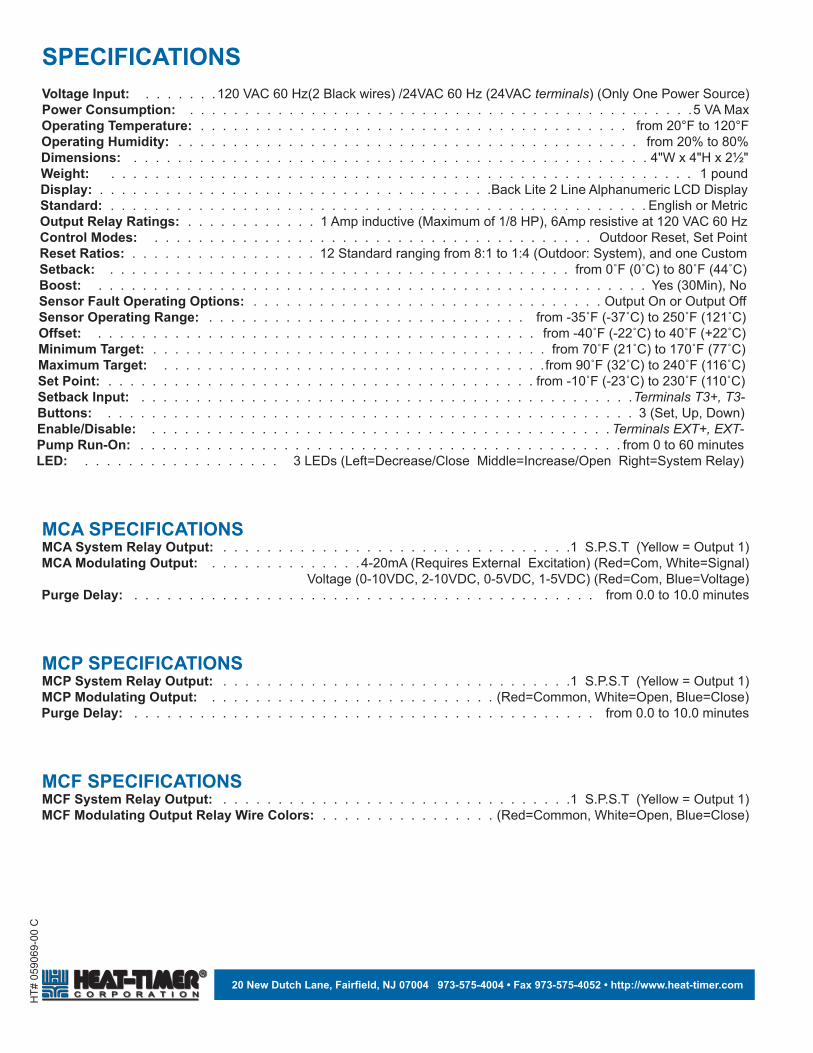
HT#
059
069-
00 C
20 new dutch lane, Fairfield, nJ 07004 973-575-4004 • Fax 973-575-4052 • http://www.heat-timer.com
sPeCiFiCationsvoltage Input: 120 VAC 60 Hz(2 Black wires) /24VAC 60 Hz (24VAC terminals) (Only One Power Source)Power Consumption: 5 VA MaxOperating Temperature: from 20°F to 120°FOperating Humidity: from 20% to 80%Dimensions: 4"W x 4"H x 2½"Weight: 1 poundDisplay: Back Lite 2 Line Alphanumeric LCD DisplayStandard: English or MetricOutput Relay Ratings: 1 Amp inductive (Maximum of 1/8 HP), 6Amp resistive at 120 VAC 60 HzControl Modes: Outdoor Reset, Set PointReset Ratios: 12 Standard ranging from 8:1 to 1:4 (Outdoor: System), and one CustomSetback: from 0˚F (0˚C) to 80˚F (44˚C)boost: Yes (30Min), Nosensor Fault operating options: Output On or Output OffSensor Operating Range: from -35˚F (-37˚C) to 250˚F (121˚C)Offset: from -40˚F (-22˚C) to 40˚F (+22˚C)Minimum Target: from 70˚F (21˚C) to 170˚F (77˚C)Maximum Target: from 90˚F (32˚C) to 240˚F (116˚C)Set Point: from -10˚F (-23˚C) to 230˚F (110˚C)Setback Input: Terminals T3+, T3-buttons: 3 (Set, Up, Down)Enable/Disable: Terminals EXT+, EXT-Pump Run-On: from 0 to 60 minutesLED: 3 LEDs (Left=Decrease/Close Middle=Increase/Open Right=System Relay)
MCa sPeCiFiCationsMCA System Relay Output: 1 S P S T (Yellow = Output 1)MCA Modulating Output: 4-20mA (Requires External Excitation) (Red=Com, White=Signal) Voltage (0-10VDC, 2-10VDC, 0-5VDC, 1-5VDC) (Red=Com, Blue=Voltage)Purge Delay: from 0 0 to 10 0 minutes
MCP sPeCiFiCationsMCP System Relay Output: 1 S P S T (Yellow = Output 1)MCP Modulating Output: (Red=Common, White=Open, Blue=Close)Purge Delay: from 0 0 to 10 0 minutes
MCF sPeCiFiCationsMCF system relay output: 1 S P S T (Yellow = Output 1)MCF Modulating output relay Wire Colors: (Red=Common, White=Open, Blue=Close)