Enhanced CXRS measurements on JET - Sprott's...
2
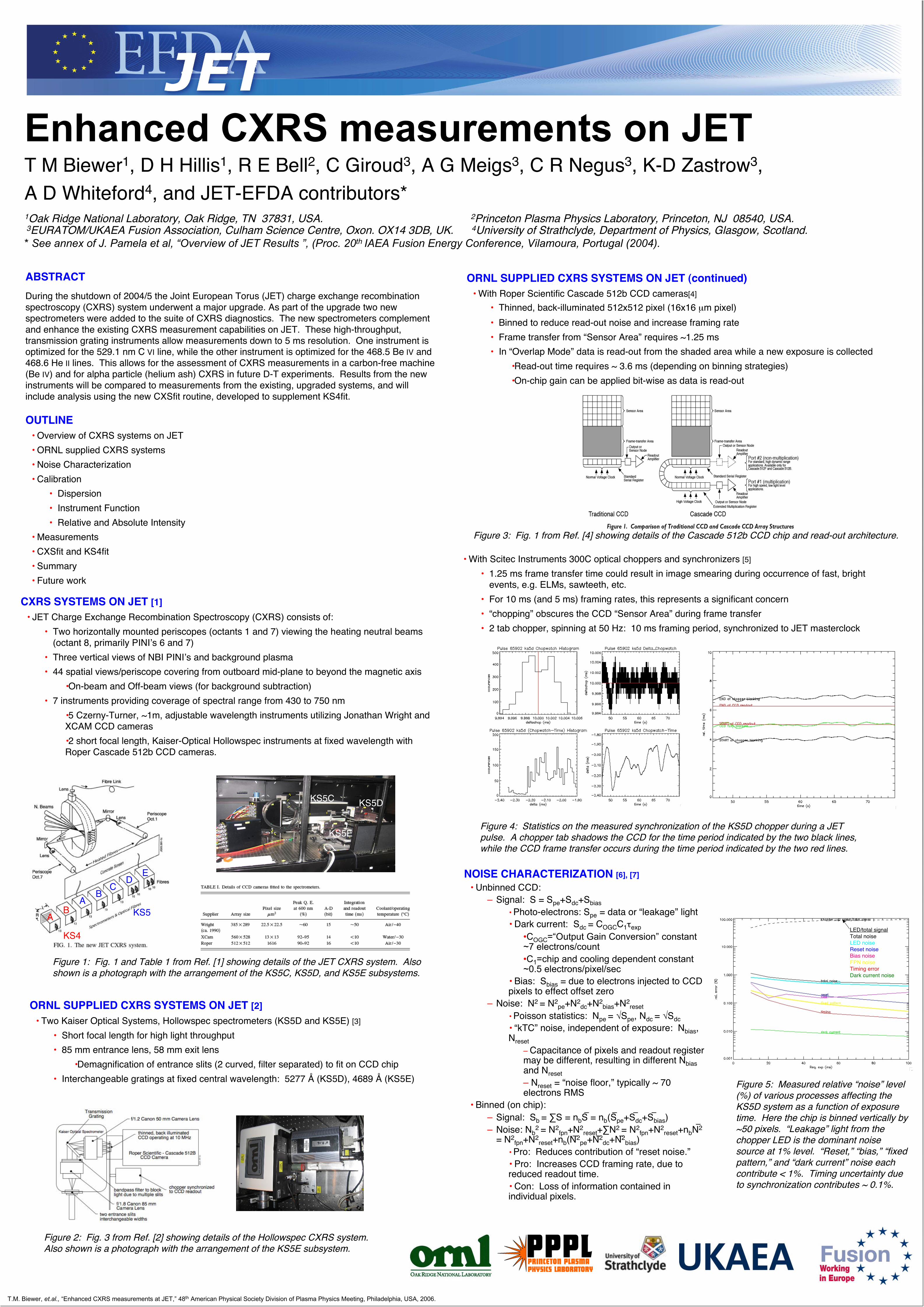
Enhanced CXRS measurements on JET T M Biewer 1 , D H Hillis 1 , R E Bell 2 , C Giroud 3 , A G Meigs 3 , C R Negus 3 , K-D Zastrow 3 , A D Whiteford 4 , and JET-EFDA contributors* 1 Oak Ridge National Laboratory, Oak Ridge, TN 37831, USA. 2 Princeton Plasma Physics Laboratory, Princeton, NJ 08540, USA. 3 EURATOM/UKAEA Fusion Association, Culham Science Centre, Oxon. OX14 3DB, UK. 4 University of Strathclyde, Department of Physics, Glasgow, Scotland. * See annex of J. Pamela et al, “Overview of JET Results ”, (Proc. 20 th IAEA Fusion Energy Conference, Vilamoura, Portugal (2004). OUTLINE • Overview of CXRS systems on JET • ORNL supplied CXRS systems • Noise Characterization • Calibration • Dispersion • Instrument Function • Relative and Absolute Intensity • Measurements • CXSfit and KS4fit • Summary • Future work ABSTRACT During the shutdown of 2004/5 the Joint European Torus (JET) charge exchange recombination spectroscopy (CXRS) system underwent a major upgrade. As part of the upgrade two new spectrometers were added to the suite of CXRS diagnostics. The new spectrometers complement and enhance the existing CXRS measurement capabilities on JET. These high-throughput, transmission grating instruments allow measurements down to 5 ms resolution. One instrument is optimized for the 529.1 nm C VI line, while the other instrument is optimized for the 468.5 Be IV and 468.6 He II lines. This allows for the assessment of CXRS measurements in a carbon-free machine (Be IV) and for alpha particle (helium ash) CXRS in future D-T experiments. Results from the new instruments will be compared to measurements from the existing, upgraded systems, and will include analysis using the new CXSfit routine, developed to supplement KS4fit. CXRS SYSTEMS ON JET [1] • JET Charge Exchange Recombination Spectroscopy (CXRS) consists of: • Two horizontally mounted periscopes (octants 1 and 7) viewing the heating neutral beams (octant 8, primarily PINI’s 6 and 7) • Three vertical views of NBI PINI’s and background plasma • 44 spatial views/periscope covering from outboard mid-plane to beyond the magnetic axis •On-beam and Off-beam views (for background subtraction) • 7 instruments providing coverage of spectral range from 430 to 750 nm •5 Czerny-Turner, ~1m, adjustable wavelength instruments utilizing Jonathan Wright and XCAM CCD cameras •2 short focal length, Kaiser-Optical Hollowspec instruments at fixed wavelength with Roper Cascade 512b CCD cameras. A B C D E A B KS5 KS4 KS5C KS5D KS5E ORNL SUPPLIED CXRS SYSTEMS ON JET (continued) • With Roper Scientific Cascade 512b CCD cameras[4] • Thinned, back-illuminated 512x512 pixel (16x16 μm pixel) • Binned to reduce read-out noise and increase framing rate • Frame transfer from “Sensor Area” requires ~1.25 ms • In “Overlap Mode” data is read-out from the shaded area while a new exposure is collected •Read-out time requires ~ 3.6 ms (depending on binning strategies) •On-chip gain can be applied bit-wise as data is read-out ORNL SUPPLIED CXRS SYSTEMS ON JET [2] • Two Kaiser Optical Systems, Hollowspec spectrometers (KS5D and KS5E) [3] • Short focal length for high light throughput • 85 mm entrance lens, 58 mm exit lens •Demagnification of entrance slits (2 curved, filter separated) to fit on CCD chip • Interchangeable gratings at fixed central wavelength: 5277 Å (KS5D), 4689 Å (KS5E) • With Scitec Instruments 300C optical choppers and synchronizers [5] • 1.25 ms frame transfer time could result in image smearing during occurrence of fast, bright events, e.g. ELMs, sawteeth, etc. • For 10 ms (and 5 ms) framing rates, this represents a significant concern • “chopping” obscures the CCD “Sensor Area” during frame transfer • 2 tab chopper, spinning at 50 Hz: 10 ms framing period, synchronized to JET masterclock T.M. Biewer, et.al., “Enhanced CXRS measurements at JET,” 48 th American Physical Society Division of Plasma Physics Meeting, Philadelphia, USA, 2006. Figure 1: Fig. 1 and Table 1 from Ref. [1] showing details of the JET CXRS system. Also shown is a photograph with the arrangement of the KS5C, KS5D, and KS5E subsystems. Figure 2: Fig. 3 from Ref. [2] showing details of the Hollowspec CXRS system. Also shown is a photograph with the arrangement of the KS5E subsystem. Figure 4: Statistics on the measured synchronization of the KS5D chopper during a JET pulse. A chopper tab shadows the CCD for the time period indicated by the two black lines, while the CCD frame transfer occurs during the time period indicated by the two red lines. Figure 3: Fig. 1 from Ref. [4] showing details of the Cascade 512b CCD chip and read-out architecture. Figure 5: Measured relative “noise” level (%) of various processes affecting the KS5D system as a function of exposure time. Here the chip is binned vertically by ~50 pixels. “Leakage” light from the chopper LED is the dominant noise source at 1% level. “Reset,” “bias,” “fixed pattern,” and “dark current” noise each contribute < 1%. Timing uncertainty due to synchronization contributes ~ 0.1%. NOISE CHARACTERIZATION [6], [7] • Unbinned CCD: – Signal: S = S pe +S dc +S bias • Photo-electrons: S pe = data or “leakage” light • Dark current: S dc = C OGC C 1 τ exp •C OGC =“Output Gain Conversion” constant ~7 electrons/count •C 1 =chip and cooling dependent constant ~0.5 electrons/pixel/sec • Bias: S bias = due to electrons injected to CCD pixels to effect offset zero – Noise: N 2 = N 2 pe +N 2 dc +N 2 bias +N 2 reset • Poisson statistics: N pe = √S pe , N dc = √S dc • “kTC” noise, independent of exposure: N bias , N reset – Capacitance of pixels and readout register may be different, resulting in different N bias and N reset – N reset = “noise floor,” typically ~ 70 electrons RMS • Binned (on chip): – Signal: S b = ∑S = n b S = n b (S pe +S dc +S bias ) – Noise: N b 2 = N 2 fpn +N 2 reset +∑N 2 = N 2 fpn +N 2 reset +n b N 2 = N 2 fpn +N 2 reset +n b (N 2 pe +N 2 dc +N 2 bias ) • Pro: Reduces contribution of “reset noise.” • Pro: Increases CCD framing rate, due to reduced readout time. • Con: Loss of information contained in individual pixels. LED/total signal Total noise LED noise Reset noise Bias noise FPN noise Timing error Dark current noise
Transcript of Enhanced CXRS measurements on JET - Sprott's...
Enhanced CXRS measurements on JETT M Biewer1, D H Hillis1, R E Bell2, C Giroud3, A G Meigs3, C R Negus3, K-D Zastrow3,A D Whiteford4, and JET-EFDA contributors*1Oak Ridge National Laboratory, Oak Ridge, TN 37831, USA. 2Princeton Plasma Physics Laboratory, Princeton, NJ 08540, USA. 3EURATOM/UKAEA Fusion Association, Culham Science Centre, Oxon. OX14 3DB, UK. 4University of Strathclyde, Department of Physics, Glasgow, Scotland.* See annex of J. Pamela et al, “Overview of JET Results ”, (Proc. 20th IAEA Fusion Energy Conference, Vilamoura, Portugal (2004).
OUTLINE• Overview of CXRS systems on JET• ORNL supplied CXRS systems• Noise Characterization• Calibration
• Dispersion• Instrument Function• Relative and Absolute Intensity
• Measurements• CXSfit and KS4fit• Summary• Future work
ABSTRACTDuring the shutdown of 2004/5 the Joint European Torus (JET) charge exchange recombinationspectroscopy (CXRS) system underwent a major upgrade. As part of the upgrade two newspectrometers were added to the suite of CXRS diagnostics. The new spectrometers complementand enhance the existing CXRS measurement capabilities on JET. These high-throughput,transmission grating instruments allow measurements down to 5 ms resolution. One instrument isoptimized for the 529.1 nm C VI line, while the other instrument is optimized for the 468.5 Be IV and468.6 He II lines. This allows for the assessment of CXRS measurements in a carbon-free machine(Be IV) and for alpha particle (helium ash) CXRS in future D-T experiments. Results from the newinstruments will be compared to measurements from the existing, upgraded systems, and willinclude analysis using the new CXSfit routine, developed to supplement KS4fit.
CXRS SYSTEMS ON JET [1]• JET Charge Exchange Recombination Spectroscopy (CXRS) consists of:
• Two horizontally mounted periscopes (octants 1 and 7) viewing the heating neutral beams(octant 8, primarily PINI’s 6 and 7)
• Three vertical views of NBI PINI’s and background plasma• 44 spatial views/periscope covering from outboard mid-plane to beyond the magnetic axis
•On-beam and Off-beam views (for background subtraction)• 7 instruments providing coverage of spectral range from 430 to 750 nm
•5 Czerny-Turner, ~1m, adjustable wavelength instruments utilizing Jonathan Wright andXCAM CCD cameras•2 short focal length, Kaiser-Optical Hollowspec instruments at fixed wavelength withRoper Cascade 512b CCD cameras.
AB
CD
E
AB KS5
KS4
KS5C KS5D
KS5E
ORNL SUPPLIED CXRS SYSTEMS ON JET (continued)• With Roper Scientific Cascade 512b CCD cameras[4]
• Thinned, back-illuminated 512x512 pixel (16x16 µm pixel)• Binned to reduce read-out noise and increase framing rate• Frame transfer from “Sensor Area” requires ~1.25 ms• In “Overlap Mode” data is read-out from the shaded area while a new exposure is collected
•Read-out time requires ~ 3.6 ms (depending on binning strategies)•On-chip gain can be applied bit-wise as data is read-out
ORNL SUPPLIED CXRS SYSTEMS ON JET [2]• Two Kaiser Optical Systems, Hollowspec spectrometers (KS5D and KS5E) [3]
• Short focal length for high light throughput• 85 mm entrance lens, 58 mm exit lens
•Demagnification of entrance slits (2 curved, filter separated) to fit on CCD chip• Interchangeable gratings at fixed central wavelength: 5277 Å (KS5D), 4689 Å (KS5E)
• With Scitec Instruments 300C optical choppers and synchronizers [5]
• 1.25 ms frame transfer time could result in image smearing during occurrence of fast, brightevents, e.g. ELMs, sawteeth, etc.
• For 10 ms (and 5 ms) framing rates, this represents a significant concern• “chopping” obscures the CCD “Sensor Area” during frame transfer• 2 tab chopper, spinning at 50 Hz: 10 ms framing period, synchronized to JET masterclock
T.M. Biewer, et.al., “Enhanced CXRS measurements at JET,” 48th American Physical Society Division of Plasma Physics Meeting, Philadelphia, USA, 2006.
Figure 1: Fig. 1 and Table 1 from Ref. [1] showing details of the JET CXRS system. Alsoshown is a photograph with the arrangement of the KS5C, KS5D, and KS5E subsystems.
Figure 2: Fig. 3 from Ref. [2] showing details of the Hollowspec CXRS system.Also shown is a photograph with the arrangement of the KS5E subsystem.
Figure 4: Statistics on the measured synchronization of the KS5D chopper during a JETpulse. A chopper tab shadows the CCD for the time period indicated by the two black lines,while the CCD frame transfer occurs during the time period indicated by the two red lines.
Figure 3: Fig. 1 from Ref. [4] showing details of the Cascade 512b CCD chip and read-out architecture.
Figure 5: Measured relative “noise” level(%) of various processes affecting theKS5D system as a function of exposuretime. Here the chip is binned vertically by~50 pixels. “Leakage” light from thechopper LED is the dominant noisesource at 1% level. “Reset,” “bias,” “fixedpattern,” and “dark current” noise eachcontribute < 1%. Timing uncertainty dueto synchronization contributes ~ 0.1%.
NOISE CHARACTERIZATION [6], [7]• Unbinned CCD:
– Signal: S = Spe+Sdc+Sbias• Photo-electrons: Spe = data or “leakage” light• Dark current: Sdc = COGCC1τexp
•COGC=“Output Gain Conversion” constant~7 electrons/count•C1=chip and cooling dependent constant~0.5 electrons/pixel/sec
• Bias: Sbias = due to electrons injected to CCDpixels to effect offset zero
– Noise: N2 = N2pe+N2
dc+N2bias+N2
reset• Poisson statistics: Npe = √Spe, Ndc = √Sdc• “kTC” noise, independent of exposure: Nbias,Nreset
– Capacitance of pixels and readout registermay be different, resulting in different Nbiasand Nreset– Nreset = “noise floor,” typically ~ 70electrons RMS
• Binned (on chip):– Signal: Sb = ∑S = nbS = nb(Spe+Sdc+Sbias)– Noise: Nb
2 = N2fpn+N2
reset+∑N2 = N2fpn+N2
reset+nbN2
= N2fpn+N2
reset+nb(N2pe+N2
dc+N2bias)
• Pro: Reduces contribution of “reset noise.”• Pro: Increases CCD framing rate, due toreduced readout time.• Con: Loss of information contained inindividual pixels.
LED/total signalTotal noiseLED noiseReset noiseBias noiseFPN noiseTiming errorDark current noise
REFERENCES[1] C.R. Negus, C. Giroud, A.G. Meigs, K.-D. Zastrow, D.L. Hillis, Rev. Sci. Inst. 77 (1), 10F102, (2006).[2] D.L. Hillis, D.T. Fehling, R.E. Bell, D.W. Johnson, et.al., Rev. Sci. Inst. 75 (10), pp. 3449-3451, (2004).[3] R.E. Bell, LE. Dudek, B. Grek, D.W. Johnson, R.W. Palladino, Rev. Sci. Inst. 70, 821 (1998).[4] User Manual for Cascade Systems, Roper Scientific, Tucson, 2003.[5] R.E. Bell, “Guide to Chopper Timing,” Princeton Plasma Physics Laboratory, 2004.[6] G.C. Holst, CCD Arrays, Cameras, and Displays, JCD Publishing, 1998.[7] J.R. Janesick, Scientific Charge-Coupled Devices, SPIE Optical Engr. Press, 2001.[8] R.E. Bell, Rev. Sci. Inst. 75, 4158, (2004).[9] Code under development; for information contact A. Whiteford ([email protected]).[10] M.G. von Hellermann, “A brief description of the JET CXRS Software,” JET Joint Undertaking, 2000.
ACKNOWLEDGEMENTS"This work, carried out under the European Fusion Development Agreement, supported by theEuropean Communities and the U.S. Dept. of Energy, has been carried out within the Contract ofAssociation between EURATOM and the U.S.D.O.E, Contract DE-AC05-00OR22725. The viewsand opinions expressed herein do not necessarily reflect those of the European Commission or theU.S.D.O.E.”
SUMMARY• Two new, short focal length, Hollowspec instruments for CXRS measurements have been
implement on JET.• These high light throughput instruments allow CXRS measurements to be made at 10 ms
resolution.• These dedicated C VI and He II CXRS instruments provide greater flexibility to the JET CXRS
suite of diagnostics, allowing the λ tuneable Czerny-Turner instruments to be utilized more fully.
FUTURE WORK• Track and wavelength dependence of instrument function needs to be fully implemented.• Comparisons between KS5C and KS5D data.• Comparisons between CXSfit and KS4fit analysis of KS5D data.• Implementation of KS5E in CXSfit.• “Realtime” implementation of KS5D data control.• CHEAPing of data from CXSfit• Preparations for 5 ms framing period operation
REPRINTSElectronic copy available at:
http://sprott.physics.wisc.edu/biewer/APS06poster.pdfSign up below to have a PDF sent to you:
MEASUREMENTS• JET Pulse Files (JPFs) are stored for KS5D and KS5E
• Data stored routinely since Spring 2006• Processed Pulse Files (PPFs) are not currently being written for KS5D or KS5E data
• Issues remain which must be resolved• Fitting routines have been written for assessment purposes, and indicate that the instruments are
performing as expected
CXSfit [9] AND KS4fit [10]• KS4fit is a FORTRAN based analysis package which has historically been used to analyze
CXRS data on JET and other plasma devices.• Quasi-graphical, command line interface• “save sets” re-run for each shot
• CXSfit is an IDL based, widget driven analysis package.• Utilizes KS4fit functional libraries to maintain continuity with past results• Flexible data input/output (machine independent)• Batch processing of sequences of machine pulses under development• Track dependent spectrometer parameters are supported• Greatly enhanced ease of data display• CXSfit is currently in “beta testing”
CALIBRATION: RELATIVE AND ABSOLUTE INTENSITY• Relative Intensity Calibration
• A white light source is used to illuminate• Absolute Intensity Calibration
• A blackbody, integrating sphere of standardized luminosity is used to illuminate all or someof the relatively calibrated fiberoptics
• Comparison of the measured photon flux to the known flux yields the absolute calibration ofeach channel.
CALIBRATION: DISPERSION• Consequences of short-focal length Hollowspec instruments
• Curved entrance slits necessary to effect straight imagesin exit plane
• Non-constant dispersion across the image plane• Dispersion can be calculated from first principles[8]
• Calibration necessary to determine “as built” dispersion• 2 entrance slits: spectra separated via optical band-pass filter• 10 fibers/slit: total of 20 spatial chords on a single instrument• KS5D: Low dispersion, transmission grating (~44 Å/mm)
• Center wavelength: 5277 Å (C VI spectra)• Optical band-pass filter range: ~ 5245 to 5325 Å• Sm calibration lamp produces cold lines in this range
• KS5E: High dispersion grating (~17 Å/mm)• Center wavelength: 4689 Å (He II spectra)• Optical band-pass filter range: ~ 4660 to 4700 Å• Xe and Ne calibration lamps used
• Polynomial fit to calibration data: λ = c0 + c1*pixel + c2*pixel2
• Variation from track-to-track in cj reduced with linear fit v. track.
CALIBRATION: INSTRUMENT FUNCTION• Instrumental broadening of spectral lines due primarily to finite entrance-slit width• An ideal, infinitesimally narrow (cold) spectral light source produces an image of the entrance slit
on the exit plane: slit image• Width of the slit image predominately due to magnification of the instrument:
• Czerny-Turner: M = fexit/fent = 1• Hollowspec: M = fexit/fent = 58 mm / 85 mm = 0.68
•KS5D: slit width = 150 µm → slit image width =102.4 µm → 6.4 pixels•KS5E: slit width = 250 µm → slit image width =170.6 µm → 10.7 pixels
• Because the dispersion is non-constant, the instrumental line width (Å) depends on location onthe CCD chip (I.e. pixel)
• left- and right-side instrumental function are different• Calibration lamps (cold) have negligible spectral line width• Fitting lines across the CCD chip gives a measure of the instrument width (pixels) at some λ
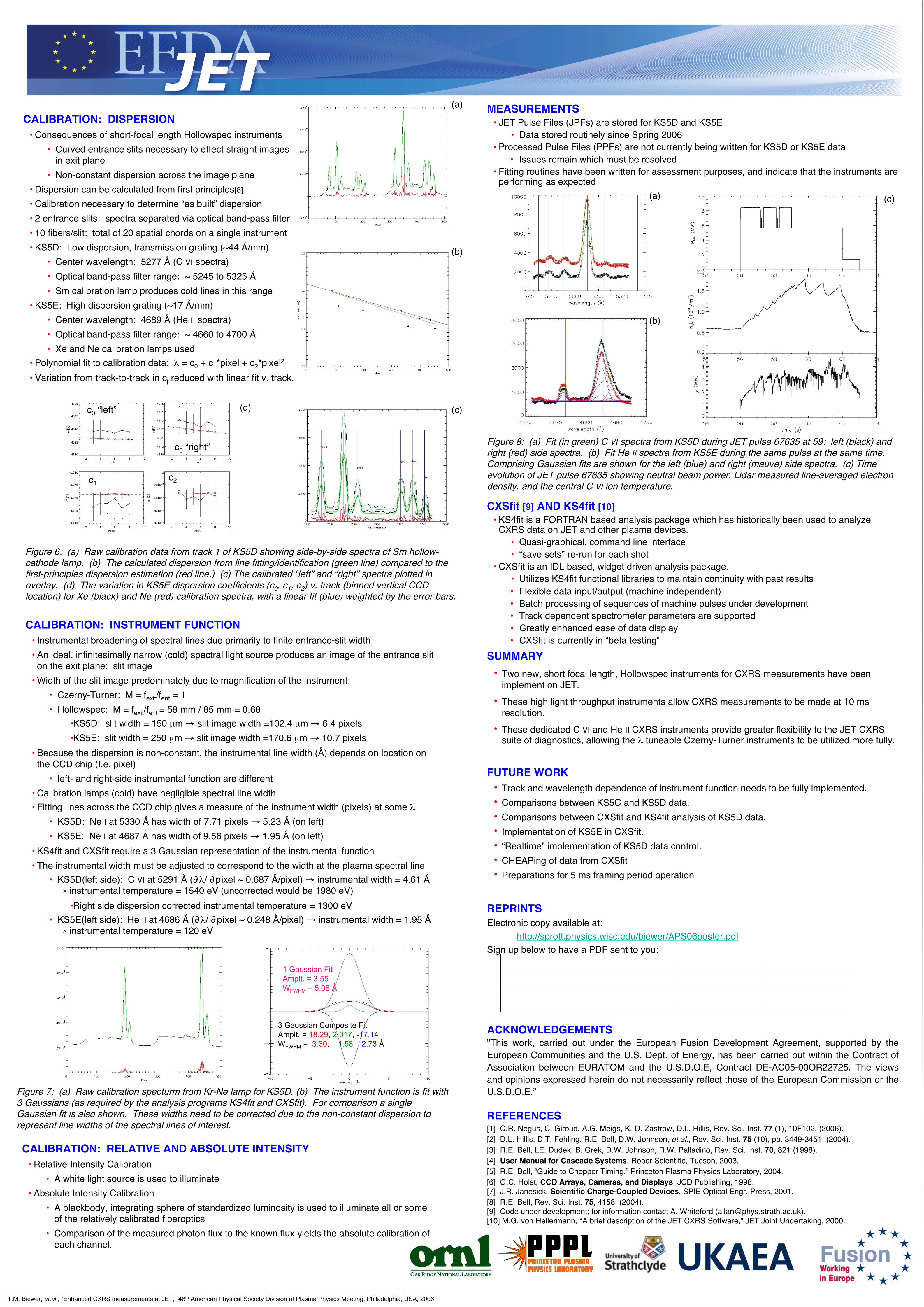
• KS5D: Ne I at 5330 Å has width of 7.71 pixels → 5.23 Å (on left)• KS5E: Ne I at 4687 Å has width of 9.56 pixels → 1.95 Å (on left)
• KS4fit and CXSfit require a 3 Gaussian representation of the instrumental function• The instrumental width must be adjusted to correspond to the width at the plasma spectral line
• KS5D(left side): C VI at 5291 Å (∂ λ/ ∂pixel ~ 0.687 Å/pixel) → instrumental width = 4.61 Å→ instrumental temperature = 1540 eV (uncorrected would be 1980 eV)
•Right side dispersion corrected instrumental temperature = 1300 eV• KS5E(left side): He II at 4686 Å (∂λ/ ∂pixel ~ 0.248 Å/pixel) → instrumental width = 1.95 Å→ instrumental temperature = 120 eV
3 Gaussian Composite FitAmplt. = 18.29, 2.017, -17.14WFWHM = 3.30, 1.58, 2.73 Å
1 Gaussian FitAmplt. = 3.55WFWHM = 5.08 Å
T.M. Biewer, et.al., “Enhanced CXRS measurements at JET,” 48th American Physical Society Division of Plasma Physics Meeting, Philadelphia, USA, 2006.
Figure 6: (a) Raw calibration data from track 1 of KS5D showing side-by-side spectra of Sm hollow-cathode lamp. (b) The calculated dispersion from line fitting/identification (green line) compared to thefirst-principles dispersion estimation (red line.) (c) The calibrated “left” and “right” spectra plotted inoverlay. (d) The variation in KS5E dispersion coefficients (c0, c1, c2) v. track (binned vertical CCDlocation) for Xe (black) and Ne (red) calibration spectra, with a linear fit (blue) weighted by the error bars.
(d) (c)
(b)
(a)
Figure 7: (a) Raw calibration specturm from Kr-Ne lamp for KS5D. (b) The instrument function is fit with3 Gaussians (as required by the analysis programs KS4fit and CXSfit). For comparison a singleGaussian fit is also shown. These widths need to be corrected due to the non-constant dispersion torepresent line widths of the spectral lines of interest.
Figure 8: (a) Fit (in green) C VI spectra from KS5D during JET pulse 67635 at 59: left (black) andright (red) side spectra. (b) Fit He II spectra from KS5E during the same pulse at the same time.Comprising Gaussian fits are shown for the left (blue) and right (mauve) side spectra. (c) Timeevolution of JET pulse 67635 showing neutral beam power, Lidar measured line-averaged electrondensity, and the central C VI ion temperature.
c0 “left”
c0 “right”
c1c2
(c)
(b)
(a)