ENGR-2300 Electronic Instrumentation Quiz 2 Fall 2014 · ENGR-2300 . Electronic Instrumentation ....
21
ENGR-2300 Quiz 2 Fall 2014 1 K. A. Connor ENGR-2300 Electronic Instrumentation Quiz 2 Fall 2014 Question I (25 points) ___________ Question II (25 points) ___________ Question III (25 points) ___________ Question IV (25 points) ___________ Total (100 points) ______________ On all questions: SHOW ALL WORK. BEGIN WITH FORMULAS, THEN SUBSTITUTE VALUES AND UNITS. No credit will be given for numbers that appear without justification. Read the entire quiz before answering any questions. Also it may be easier to answer parts of questions out of order.
Transcript of ENGR-2300 Electronic Instrumentation Quiz 2 Fall 2014 · ENGR-2300 . Electronic Instrumentation ....
ENGR-2300 Quiz 2 Fall 2014
1 K. A. Connor
ENGR-2300
Electronic Instrumentation
Quiz 2
Fall 2014
Question I (25 points) ___________
Question II (25 points) ___________
Question III (25 points) ___________
Question IV (25 points) ___________
Total (100 points) ______________
On all questions: SHOW ALL WORK. BEGIN WITH FORMULAS, THEN SUBSTITUTE VALUES AND UNITS. No credit will be given for numbers that appear without justification. Read the entire quiz before answering any questions. Also it may be easier to answer parts of questions out of order.
ENGR-2300 Quiz 2 Fall 2014
2 K. A. Connor
Ebbets Field Hosts Football History The now-essential relationship between pro football and television actually began on October 22, 1939. That’s when the National Broadcasting Company earned a spot in pro football history by becoming the first network to televise a pro football game.
A meager crowd of 13,050 were on hand at Brooklyn’s Ebbets Field on that now-historic day when the Philadelphia Eagles fell to Brooklyn’s Dodgers 23-14. The game included play by three future Hall of Famers - quarterback Ace Parker and tackle Bruiser Kinard for the Dodgers and end Bill Hewitt for the Eagles.
Five hundred-or-so fortunate New Yorkers who owned television sets witnessed the game in the comfort of their own homes, over NBC’s experimental station W2XBS. Many others saw the telecast on monitors while visiting the RCA Pavilion at the World’s Fair in New York where it was scheduled as a special event.
- See more at: http://www.profootballhof.com/history/decades/1930s/first_televised_game.aspx
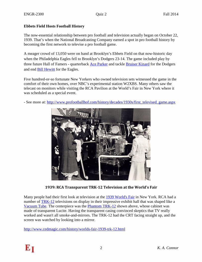
1939: RCA Transparent TRK-12 Television at the World's Fair
Many people had their first look at television at the 1939 World's Fair in New York. RCA had a number of TRK-12 televisions on display in their impressive exhibit hall that was shaped like a Vacuum Tube. The centerpiece was the Phantom TRK-12 shown above, whose cabinet was made of transparent Lucite. Having the transparent casing convinced skeptics that TV really worked and wasn't all smoke-and-mirrors. The TRK-12 had the CRT facing straight up, and the screen was watched by looking into a mirror.
http://www.cedmagic.com/history/worlds-fair-1939-trk-12.html
ENGR-2300 Quiz 2 Fall 2014
3 K. A. Connor
Think-Pair-Share Topics:
1. None 2. (Exp 1) Hand-drawn circuit diagram … one of the key tasks for every experiment and
simulation you do involving a circuit is to draw the circuit diagram by hand before you begin building it or setting up the simulation. Give two reasons why this will be helpful for you and your team.
3. (Exp 1) What is a resistor … what is an inductor … what is a capacitor? Describe at least two of the three devices in some useful manner. Give a practical example of something that is not a typical circuit component, but electrically is one of these devices. (e.g. A person can be any of the three. In the winter, we are capacitors when we charge up walking across a carpeted floor and then give shocks to the people we touch.)
4. (Exp 2) What is meant by a low frequency or a high frequency when dealing with RC, RL or RLC circuits?
5. (Exp 2) In ideal circuit models, resistors are resistors, inductors are inductors and capacitors are capacitors. Is this also true for real devices? What examples can you think of that are at least two or maybe all three of these devices at the same time?
6. (Exp 3) What is the purpose of an ideal model for an inductor if the analytical formula we can derive from it does not provide a particularly accurate prediction of inductance? How can you make practical use of such models?
7. (Exp 3) We investigate two different ways of measuring inductance in Experiment 3. What other techniques can you think of? Can you think of an application of an inductance measurement as a sensor of some kind?
8. (Exp 3/Proj 1) When is a transformer a transformer? What is it when it is not a transformer? Is this a really strange question? Note that this is an electrical question and has nothing to do with the toys or animated characters.
9. (Proj 1) Pick a moving object of interest to you and suggest two or three different techniques for determining its velocity.
10. (Exp 4) Describe 2 or 3 techniques for troubleshooting a circuit. Apply your ideas to one of the more complex circuits from this course.
11. (Exp 4) How and why do practical op-amp differentiators and integrators differ from their ideal counterparts? How do we verify that they are indeed integrating or differentiating?
12. (Exp 5) What is a damped harmonic oscillator? What real-world examples of such harmonic oscillators can you identify?
13. (Exp 5) What is the Thevenin equivalent circuit and why is it useful? What is the Thevenin equivalent circuit for a standard 9V battery?
ENGR-2300 Quiz 2 Fall 2014
4 K. A. Connor
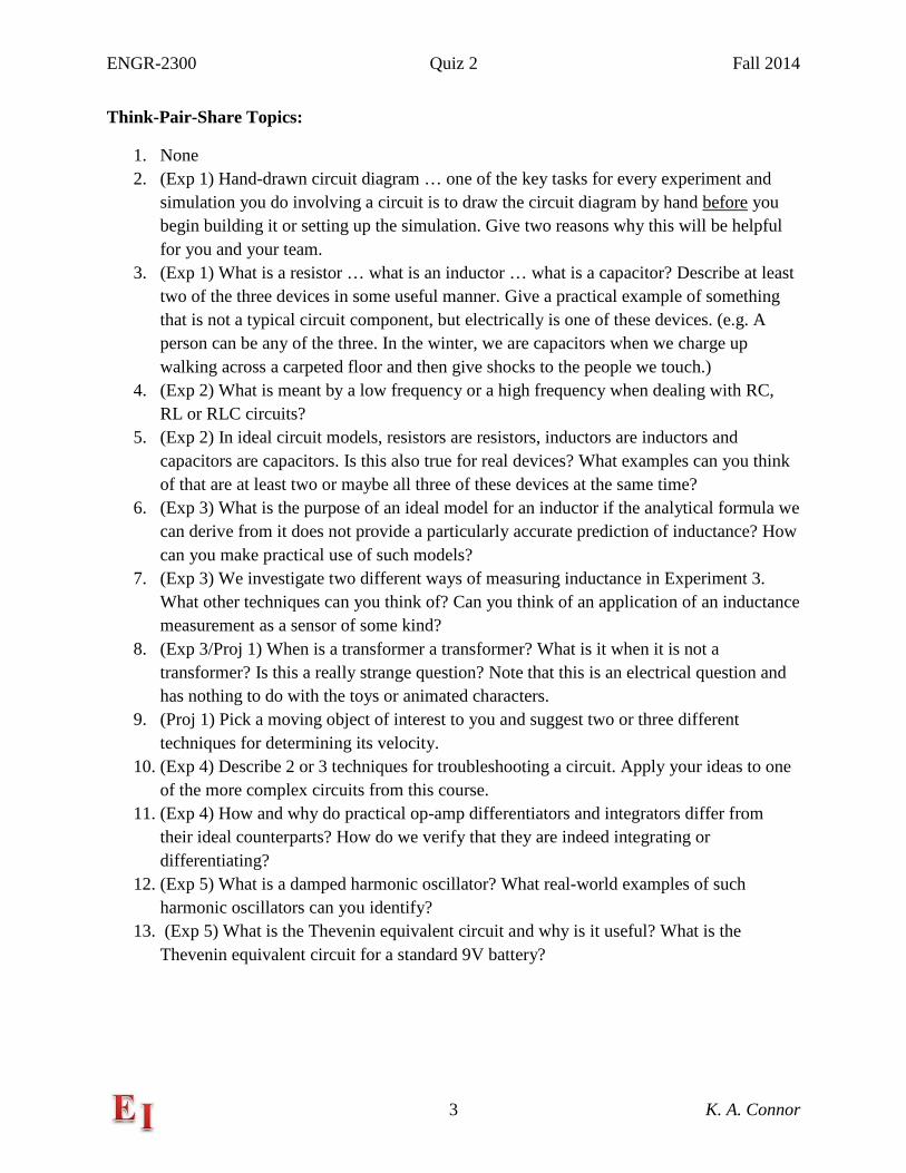
Additional Information
Shown Above is the Cantilever Beam with a Commercial Guitar Pickup as a Sensor
Analog Discovery
Connections
ENGR-2300 Quiz 2 Fall 2014
5 K. A. Connor
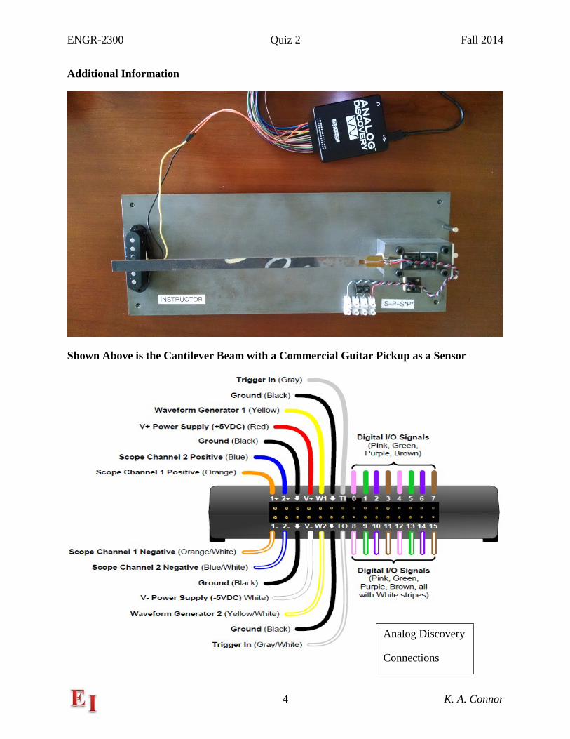
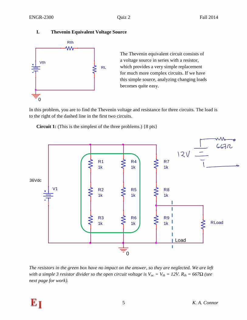
I. Thevenin Equivalent Voltage Source
In this problem, you are to find the Thevenin voltage and resistance for three circuits. The load is to the right of the dashed line in the first two circuits.
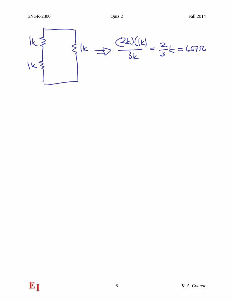
Circuit 1: (This is the simplest of the three problems.) 8 pts
The resistors in the green box have no impact on the answer, so they are neglected. We are left with a simple 3 resistor divider so the open circuit voltage is Voc = Vth = 12V. Rth = 667Ω (see next page for work).
Rth
RLVth
0
V1
36Vdc
R11k
R21k
R31k
R41k
R51k
R61k
R71k
R81k
R91k
0
RLoad
The Thevenin equivalent circuit consists of a voltage source in series with a resistor, which provides a very simple replacement for much more complex circuits. If we have this simple source, analyzing changing loads becomes quite easy.
Load
ENGR-2300 Quiz 2 Fall 2014
6 K. A. Connor
ENGR-2300 Quiz 2 Fall 2014
7 K. A. Connor
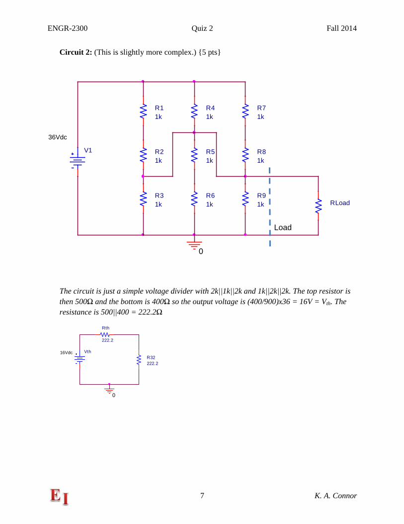
Circuit 2: (This is slightly more complex.) 5 pts
The circuit is just a simple voltage divider with 2k||1k||2k and 1k||2k||2k. The top resistor is then 500Ω and the bottom is 400Ω so the output voltage is (400/900)x36 = 16V = Vth. The resistance is 500||400 = 222.2Ω
V1
36Vdc
R11k
R21k
R31k
R41k
R51k
R61k
R71k
R81k
R91k
0
RLoad
Vth16Vdc
Rth
222.2
R32222.2
0
Load
ENGR-2300 Quiz 2 Fall 2014
8 K. A. Connor
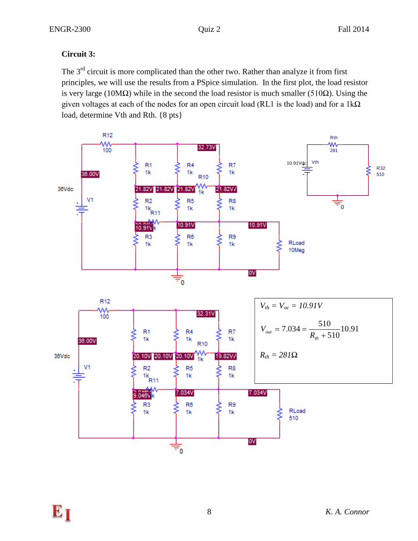
Circuit 3:
The 3rd circuit is more complicated than the other two. Rather than analyze it from first principles, we will use the results from a PSpice simulation. In the first plot, the load resistor is very large (10MΩ) while in the second the load resistor is much smaller (510Ω). Using the given voltages at each of the nodes for an open circuit load (RL1 is the load) and for a 1kΩ load, determine Vth and Rth. 8 pts
Vth = Voc = 10.91V
91.10510
510034.7+
==th
out RV
Rth = 281Ω
Vth10.91Vdc
Rth
281
R32510
0
ENGR-2300 Quiz 2 Fall 2014
9 K. A. Connor
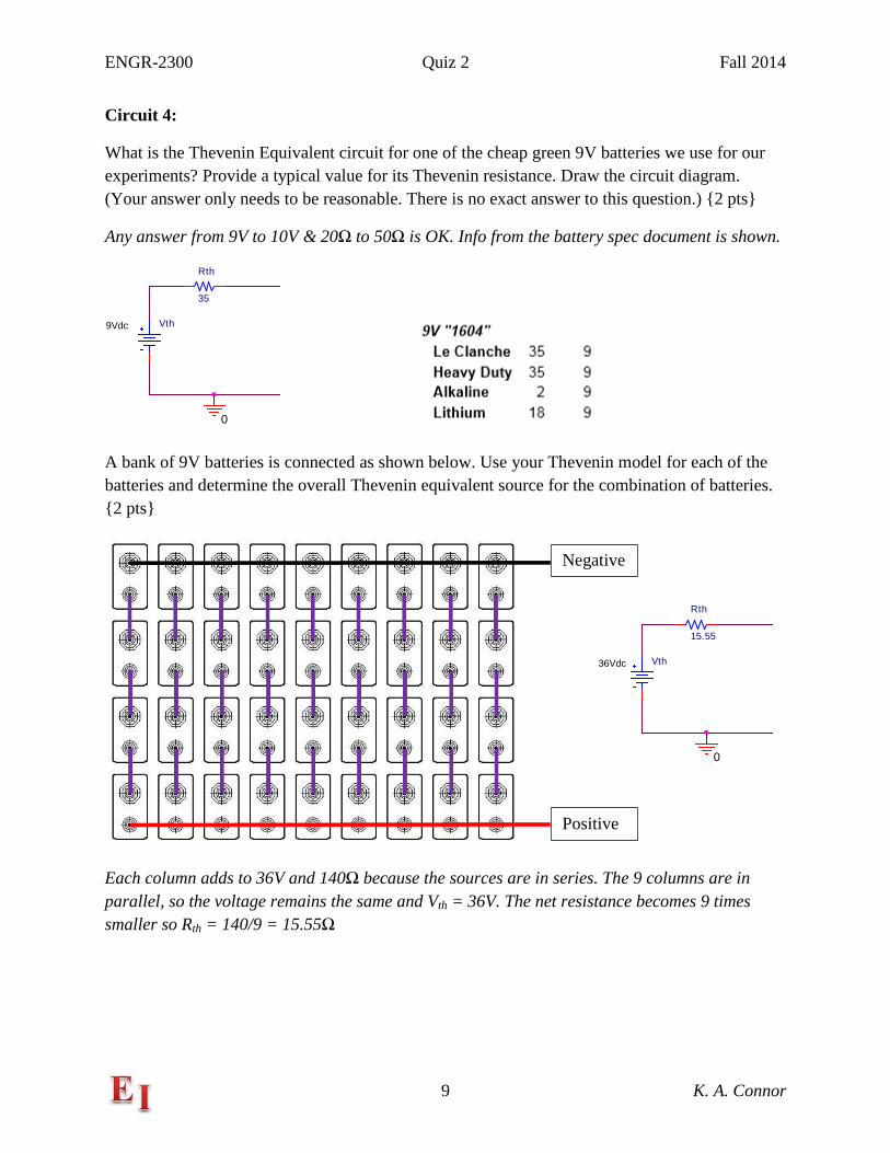
Circuit 4:
What is the Thevenin Equivalent circuit for one of the cheap green 9V batteries we use for our experiments? Provide a typical value for its Thevenin resistance. Draw the circuit diagram. (Your answer only needs to be reasonable. There is no exact answer to this question.) 2 pts
Any answer from 9V to 10V & 20Ω to 50Ω is OK. Info from the battery spec document is shown.
A bank of 9V batteries is connected as shown below. Use your Thevenin model for each of the batteries and determine the overall Thevenin equivalent source for the combination of batteries. 2 pts
Each column adds to 36V and 140Ω because the sources are in series. The 9 columns are in parallel, so the voltage remains the same and Vth = 36V. The net resistance becomes 9 times smaller so Rth = 140/9 = 15.55Ω
Vth9Vdc
Rth
35
0
Negative
Positive
Vth36Vdc
Rth
15.55
0
ENGR-2300 Quiz 2 Fall 2014
10 K. A. Connor
II. Harmonic Oscillators
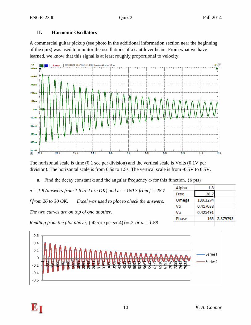
A commercial guitar pickup (see photo in the additional information section near the beginning of the quiz) was used to monitor the oscillations of a cantilever beam. From what we have learned, we know that this signal is at least roughly proportional to velocity.
The horizontal scale is time (0.1 sec per division) and the vertical scale is Volts (0.1V per division). The horizontal scale is from 0.5s to 1.5s. The vertical scale is from -0.5V to 0.5V.
a. Find the decay constant α and the angular frequency ω for this function. 6 pts
α = 1.8 (answers from 1.6 to 2 are OK) and ω = 180.3 from f = 28.7
f from 26 to 30 OK. Excel was used to plot to check the answers.
The two curves are on top of one another.
Reading from the plot above, 2.))4(.exp()425(. =−α or α = 1.88
-0.6
-0.4
-0.2
0
0.2
0.4
0.6
128
456
785
011
3314
1616
9919
8222
6525
4828
3131
1433
9736
8039
6342
4645
2948
1250
9553
7856
6159
4462
2765
1067
9370
7673
5976
4279
25
Series1
Series2
ENGR-2300 Quiz 2 Fall 2014
11 K. A. Connor
b. Write the mathematical expression for the voltage in the form tAetV t ωα cos)( −= . Use real values for the constants and provide units where appropriate. Note that the data show a phase shift, but we are neglecting that here. 4 pts
tetV t 3.180cos425.)( 8.1−=
c. From our assumption that the velocity is proportional to this voltage signal, we know we can write it as tBetv t ωα cos)( −= . Keeping only the largest terms, we also know that the
beam displacement must be given by tCetx t ωα sin)( −= . Assume also that the beam displacement at time t = 0.5s (the left end of the plot) is 2mm, determine the constant B in the expression for the velocity. Include units in your answer. Hint: Keep only the largest terms in your expressions. 6 pts
tetx t ωα sin002.)( −= When we take the derivative of this to get velocity, the largest term comes from the sine because the damping is small. Then B = .002ω = 0.36 m/s.
tetetvtx tt ωωωα αα cos002.sin002).()()( −− +−== but we keep only the second term because it is so much larger.
ENGR-2300 Quiz 2 Fall 2014
12 K. A. Connor
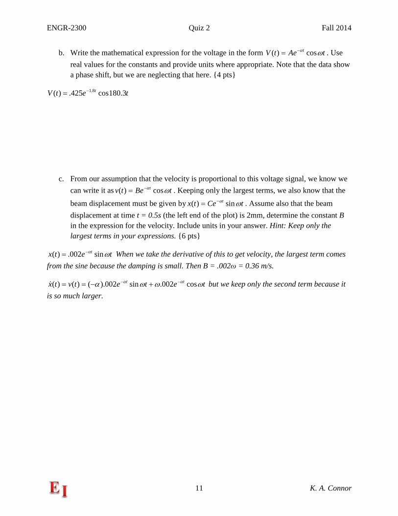
d. A function generator is used to generate a triangle wave, as shown below.
Write the mathematical expression for the voltage as a function of time for the time period between the two solid vertical lines (from t = .9875 to t = 1.0125). Note that horizontal time scale goes from 0.95s to 1.05s in steps of 0.01s per division. 5 pts
)1(1602)()( −+=−+= tttbatv o
Checking at t = 1 v = 2 so OK
Checking at t = 1.0125 v = 4 so OK
e. Determine the derivative of your function from part d. Next, assume this voltage function is the input to an ideal, active differentiator (described on the formula sheet) with Rin = 1kΩ and Cf = 0.33µF. Determine the output voltage of this circuit for the given input. 4 pts
160)( =tv and from the differentiator, 053.0160)( =−= RCtV
ENGR-2300 Quiz 2 Fall 2014
13 K. A. Connor
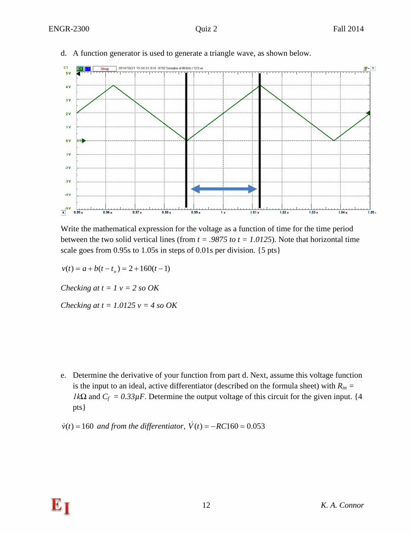
III. Operational Amplifiers
a. 2 pts What type of amplifier is each circuit? a. A Inverting Amplifier b. B Non-Inverting Amplifier c. C Integrator d. D Differentiator
For the next four parts to this question, the input voltage will be in one of the following forms (sine, square, triangle, sawtooth). In all cases, the frequency will be 1kHz and the peak-to-peak amplitude will be 200mV. None of these signals has a DC offset.
A B
C D
ENGR-2300 Quiz 2 Fall 2014
14 K. A. Connor
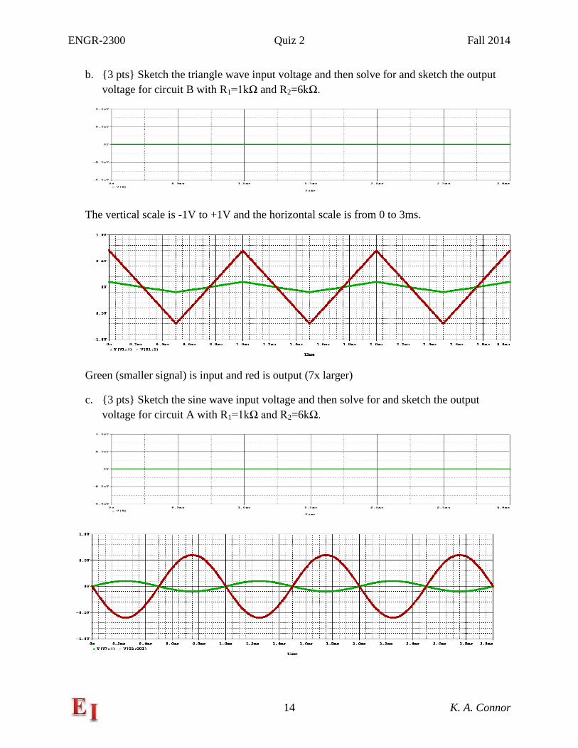
b. 3 pts Sketch the triangle wave input voltage and then solve for and sketch the output voltage for circuit B with R1=1kΩ and R2=6kΩ.
The vertical scale is -1V to +1V and the horizontal scale is from 0 to 3ms.
Green (smaller signal) is input and red is output (7x larger)
c. 3 pts Sketch the sine wave input voltage and then solve for and sketch the output voltage for circuit A with R1=1kΩ and R2=6kΩ.
ENGR-2300 Quiz 2 Fall 2014
15 K. A. Connor
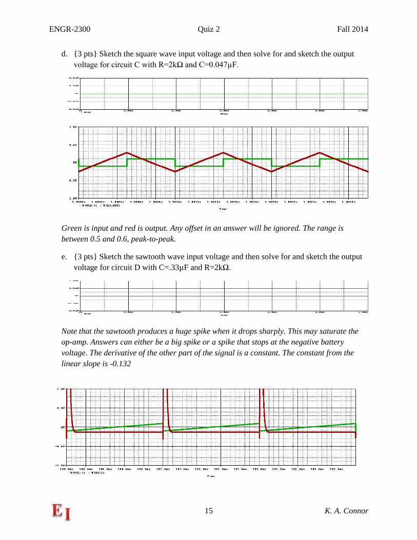
d. 3 pts Sketch the square wave input voltage and then solve for and sketch the output voltage for circuit C with R=2kΩ and C=0.047µF.
Green is input and red is output. Any offset in an answer will be ignored. The range is between 0.5 and 0.6, peak-to-peak.
e. 3 pts Sketch the sawtooth wave input voltage and then solve for and sketch the output voltage for circuit D with C=.33µF and R=2kΩ.
Note that the sawtooth produces a huge spike when it drops sharply. This may saturate the op-amp. Answers can either be a big spike or a spike that stops at the negative battery voltage. The derivative of the other part of the signal is a constant. The constant from the linear slope is -0.132
ENGR-2300 Quiz 2 Fall 2014
16 K. A. Connor
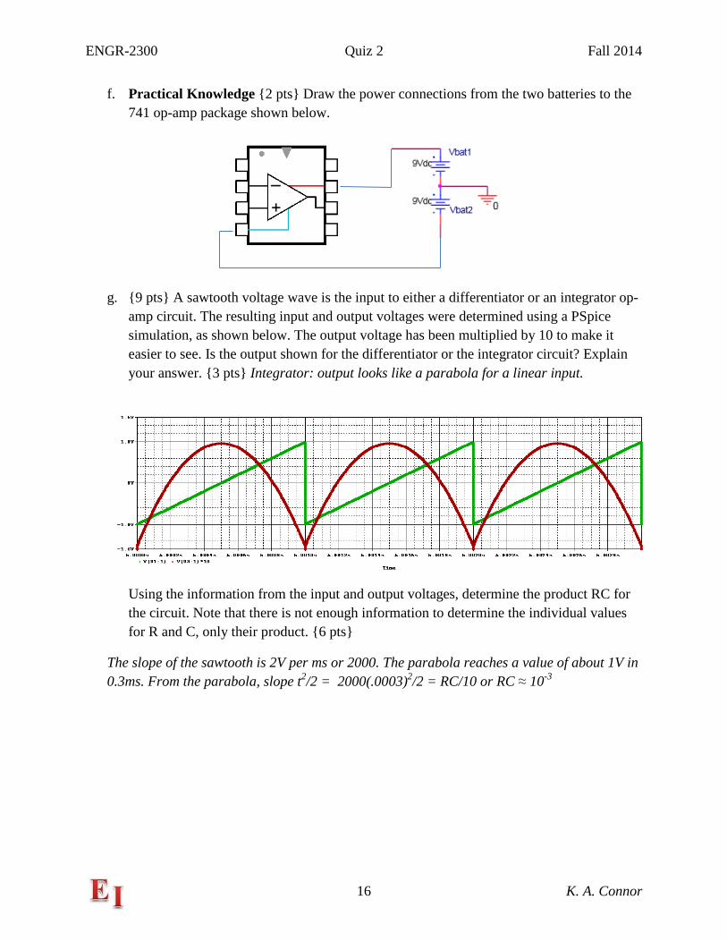
f. Practical Knowledge 2 pts Draw the power connections from the two batteries to the 741 op-amp package shown below.
g. 9 pts A sawtooth voltage wave is the input to either a differentiator or an integrator op-amp circuit. The resulting input and output voltages were determined using a PSpice simulation, as shown below. The output voltage has been multiplied by 10 to make it easier to see. Is the output shown for the differentiator or the integrator circuit? Explain your answer. 3 pts Integrator: output looks like a parabola for a linear input.
Using the information from the input and output voltages, determine the product RC for the circuit. Note that there is not enough information to determine the individual values for R and C, only their product. 6 pts
The slope of the sawtooth is 2V per ms or 2000. The parabola reaches a value of about 1V in 0.3ms. From the parabola, slope t2/2 = 2000(.0003)2/2 = RC/10 or RC ≈ 10-3
ENGR-2300 Quiz 2 Fall 2014
17 K. A. Connor
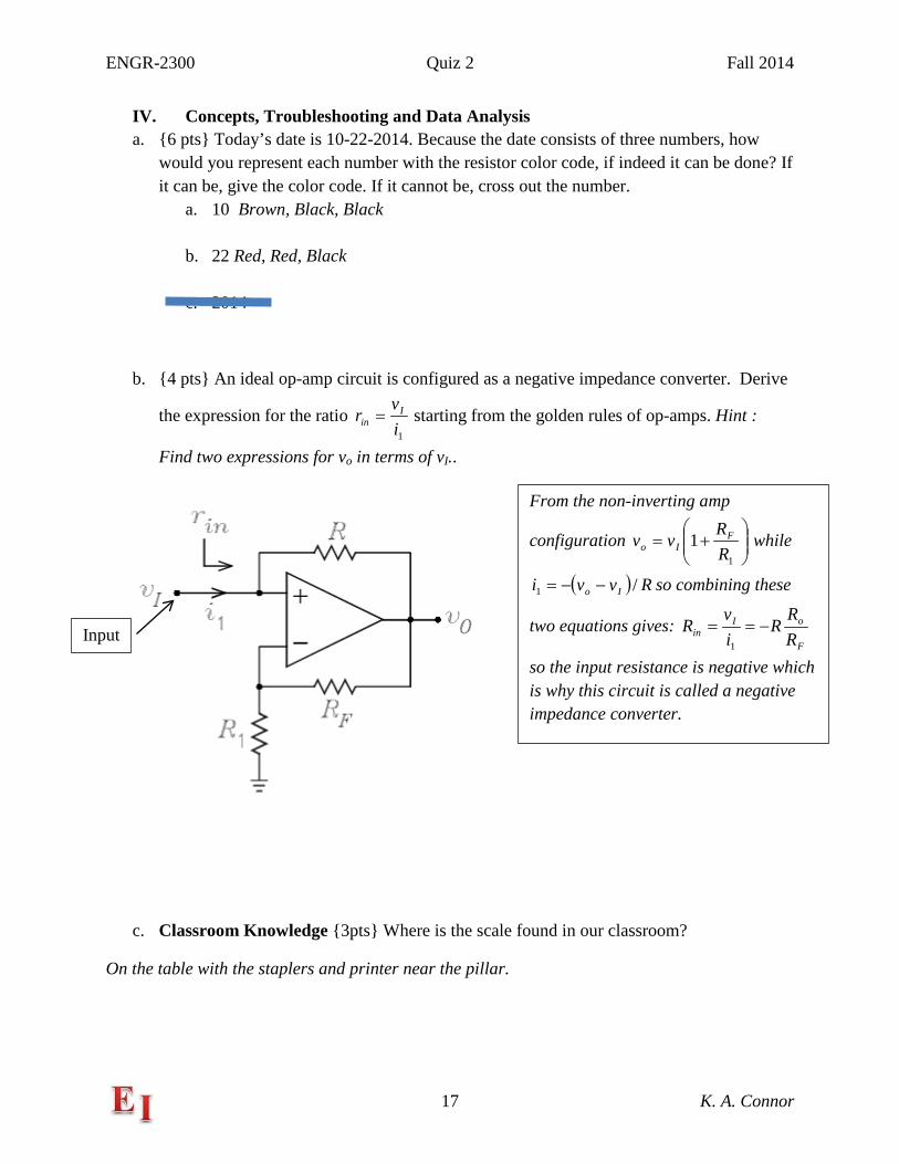
IV. Concepts, Troubleshooting and Data Analysis a. 6 pts Today’s date is 10-22-2014. Because the date consists of three numbers, how
would you represent each number with the resistor color code, if indeed it can be done? If it can be, give the color code. If it cannot be, cross out the number.
a. 10 Brown, Black, Black
b. 22 Red, Red, Black
c. 2014
b. 4 pts An ideal op-amp circuit is configured as a negative impedance converter. Derive
the expression for the ratio 1i
vr Iin = starting from the golden rules of op-amps. Hint :
Find two expressions for vo in terms of vI..
c. Classroom Knowledge 3pts Where is the scale found in our classroom?
On the table with the staplers and printer near the pillar.
Input
From the non-inverting amp
configuration
+=
1
1RRvv F
Io while
( ) Rvvi Io /1 −−= so combining these
two equations gives: F
oIin R
RR
ivR −==
1
so the input resistance is negative which is why this circuit is called a negative impedance converter.
ENGR-2300 Quiz 2 Fall 2014
18 K. A. Connor
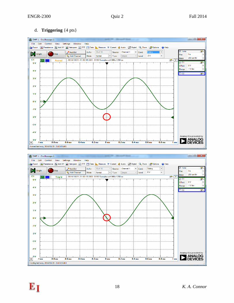
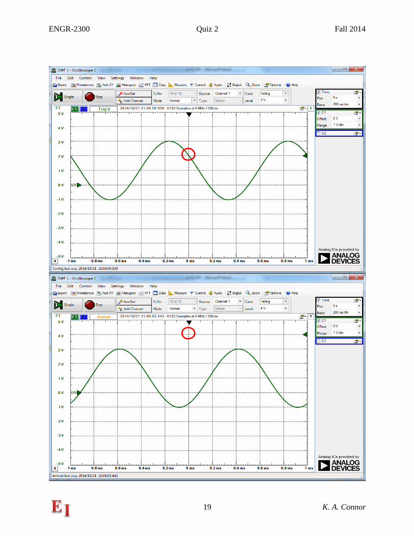
d. Triggering 4 pts
ENGR-2300 Quiz 2 Fall 2014
19 K. A. Connor
ENGR-2300 Quiz 2 Fall 2014
20 K. A. Connor
For each of the four plots above (for a 1kHz sine wave, amplitude = 2V, offset = 1V, data taken with Analog Discovery scope), triggering is set for normal mode, channel 1 and falling. Circle the triggering point for each plot 2 pts and indicate which two plots are triggering as specified and which are not. 2 pts Note – one of the triggering points has been circled for guidance.
The second and third one are triggering properly.
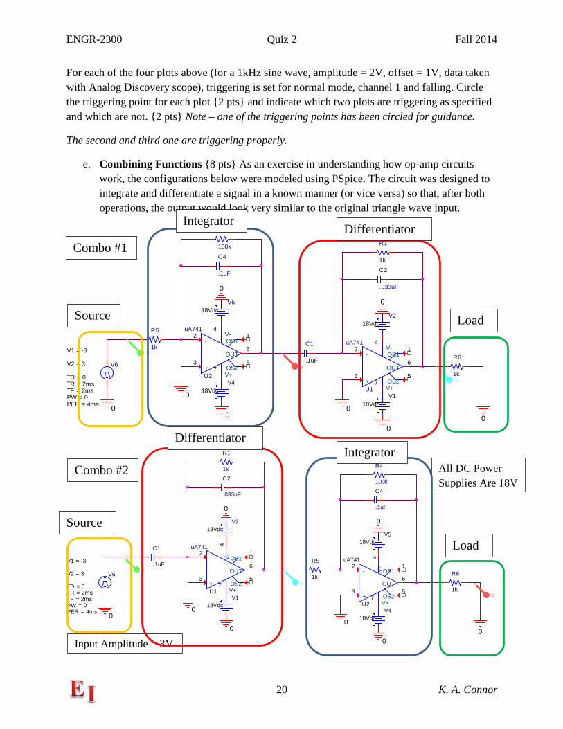
e. Combining Functions 8 pts As an exercise in understanding how op-amp circuits work, the configurations below were modeled using PSpice. The circuit was designed to integrate and differentiate a signal in a known manner (or vice versa) so that, after both operations, the output would look very similar to the original triangle wave input.
U1
uA741
+3
-2
V+7
V-4
OUT6
OS11
OS25
R1
1k
C1
.1uF
C2
.033uF
V118Vdc
V218Vdc
0
0
0
U2
uA741
+3
-2
V+7
V-4
OUT6
OS11
OS25
R4
100k
R5
1k
C4
.1uF
V418Vdc
V518Vdc
0 0
0
R6
1k
0
V6
TD = 0
TF = 2msPW = 0PER = 4ms
V1 = -3
TR = 2ms
V2 = 3
0
V
V
V
U1
uA741
+3
-2
V+7
V-
4
OUT6
OS11
OS25
R1
1k
C1
.1uF
C2
.033uF
V118Vdc
V218Vdc
0
0
0U2
uA741
+3
-2
V+7
V-
4
OUT6
OS11
OS25
R4
100k
R5
1k
C4
.1uF
V418Vdc
V518Vdc
0
00
R6
1k
0
V6
TD = 0
TF = 2msPW = 0PER = 4ms
V1 = -3
TR = 2ms
V2 = 3
0
V
V
V
Combo #1
Combo #2
Input Amplitude = 3V
All DC Power Supplies Are 18V
Source
Source
Load
Load
Integrator
Integrator
Differentiator
Differentiator
ENGR-2300 Quiz 2 Fall 2014
21 K. A. Connor
In each of the two circuits above (Combo #1 & Combo #2), label the integrator, the differentiator, the source and the load. 4 pts Source – orange, integrator – blue, load – green, differentiator – red.
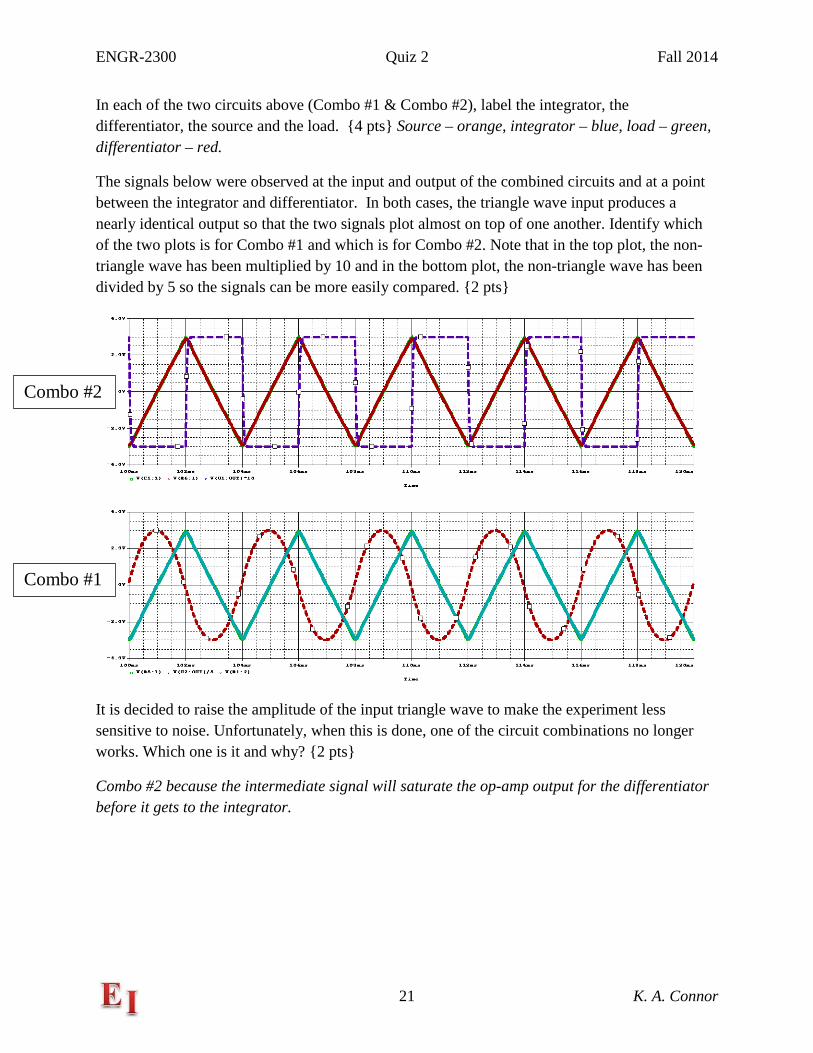
The signals below were observed at the input and output of the combined circuits and at a point between the integrator and differentiator. In both cases, the triangle wave input produces a nearly identical output so that the two signals plot almost on top of one another. Identify which of the two plots is for Combo #1 and which is for Combo #2. Note that in the top plot, the non-triangle wave has been multiplied by 10 and in the bottom plot, the non-triangle wave has been divided by 5 so the signals can be more easily compared. 2 pts
It is decided to raise the amplitude of the input triangle wave to make the experiment less sensitive to noise. Unfortunately, when this is done, one of the circuit combinations no longer works. Which one is it and why? 2 pts
Combo #2 because the intermediate signal will saturate the op-amp output for the differentiator before it gets to the integrator.
Combo #2
Combo #1