217-225, 2008 Hepatocytes, rather than leukocytes reverse ...
date post
20-Dec-2015Category
view
225download
2
ENGR 225Section 1.3 – 1.6
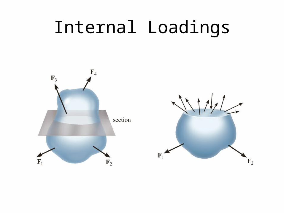
Internal Loadings
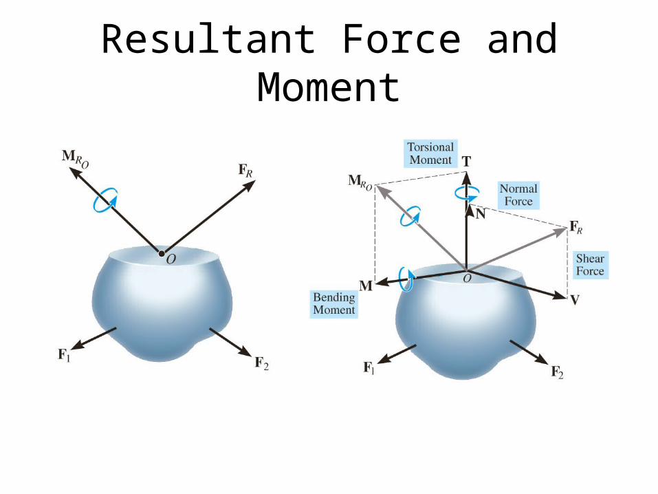
Resultant Force and Moment
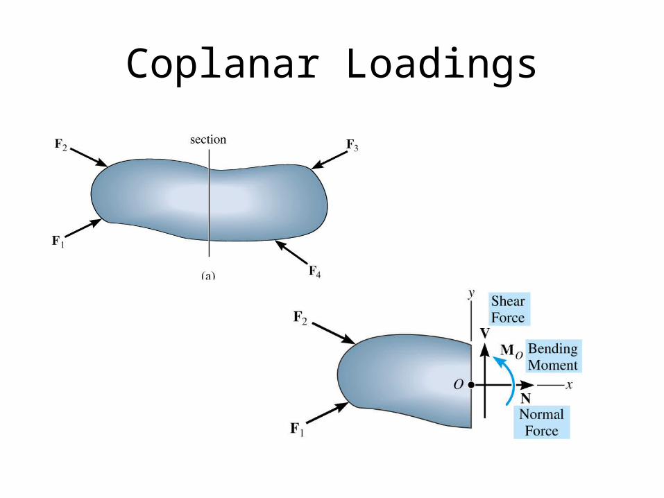
Coplanar Loadings
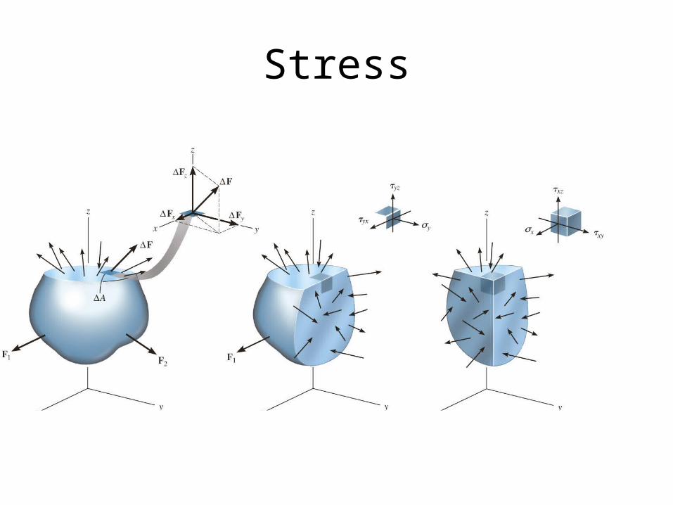
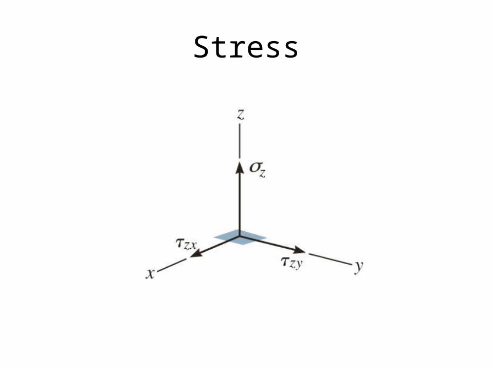
Stress
Stress Derivation
• A very small finite force ΔF is acting on an associated area ΔA.
• Replace this force with its directional components, ΔFx, ΔFy, and ΔFz.
• Take the limit as ΔA approaches zero of the quotient of the component forces and the areas
• This quotient is called, stress. It represents the intensity of the force on a specified plane.
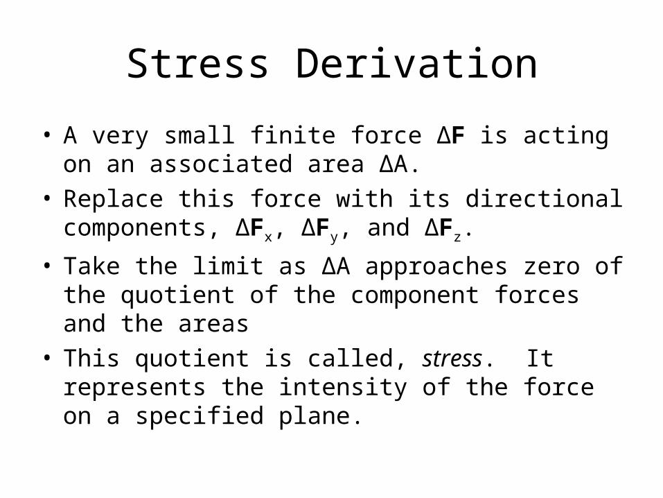
Normal Stress, σz
• The intensity of force per unit area acting normal to ΔA.
A
FzA
z
0
lim
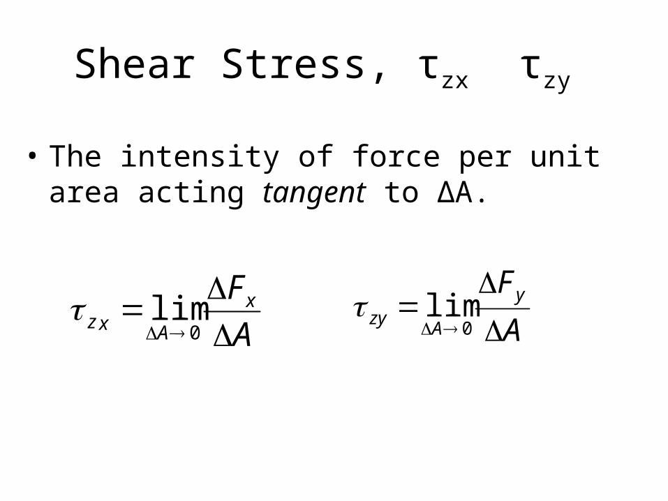
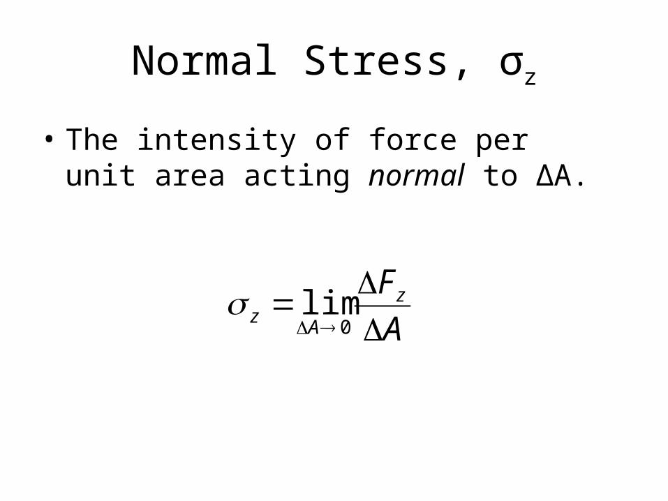
Shear Stress, τzx τzy
• The intensity of force per unit area acting tangent to ΔA.
A
FxAxz
0lim
A
FyA
zy
0
lim
Stress
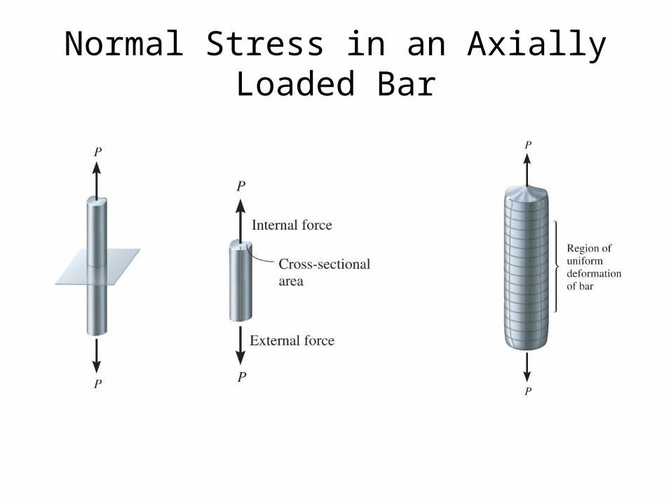
Normal Stress in an Axially Loaded Bar
A
FzA
z
0
lim
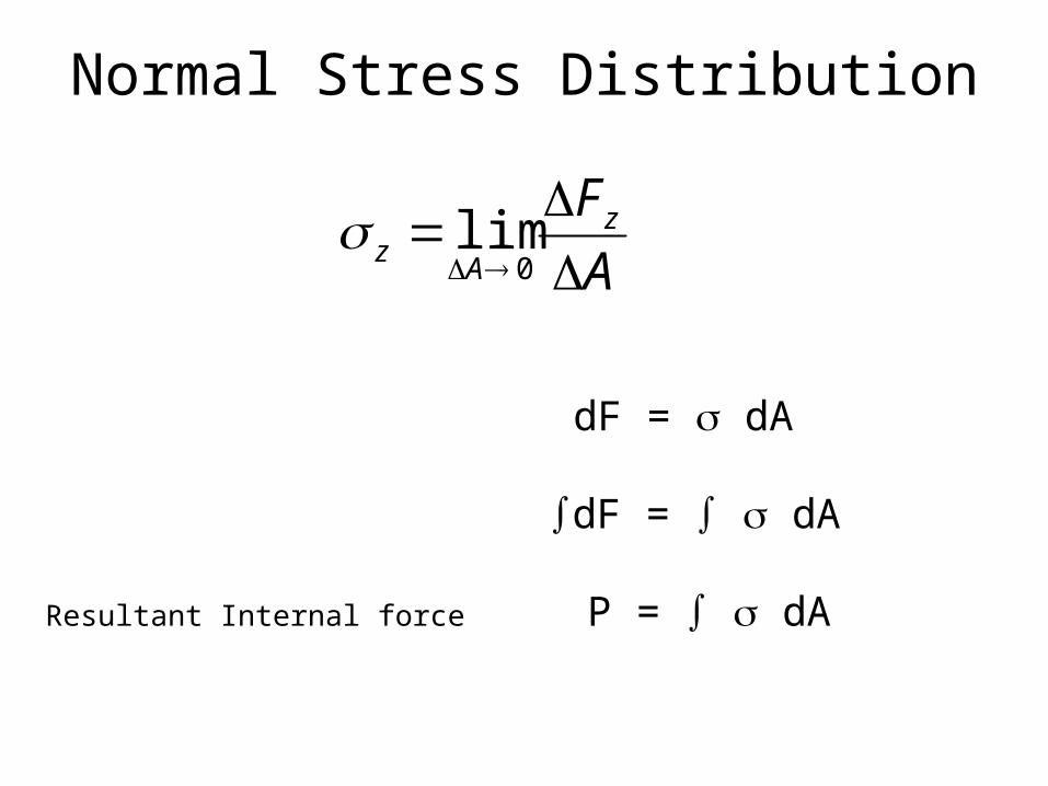
Normal Stress Distribution
dF = dA
dF = dA
Resultant Internal force P = dA
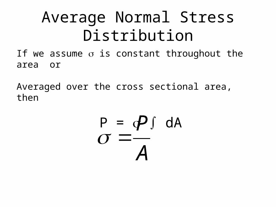
Average Normal Stress Distribution
A
P
If we assume is constant throughout the area or
Averaged over the cross sectional area, then
P = dA
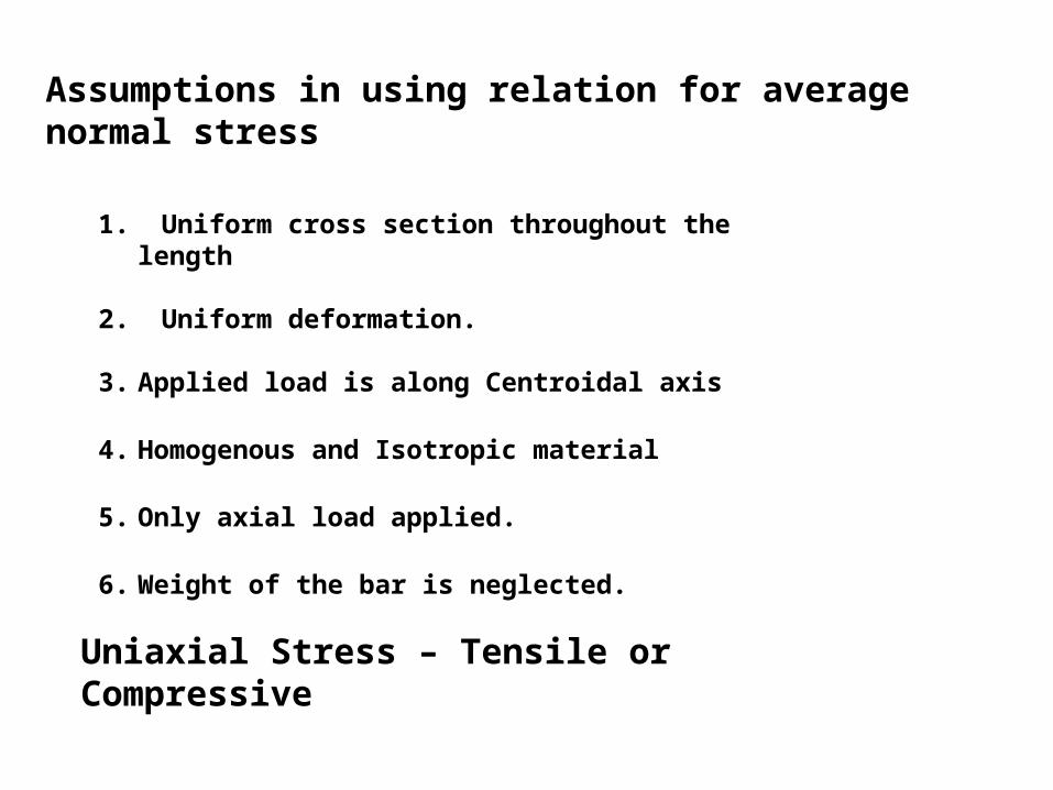
Assumptions in using relation for average normal stress
1. Uniform cross section throughout the length
2. Uniform deformation.
3. Applied load is along Centroidal axis
4. Homogenous and Isotropic material
5. Only axial load applied.
6. Weight of the bar is neglected.
Uniaxial Stress – Tensile or Compressive
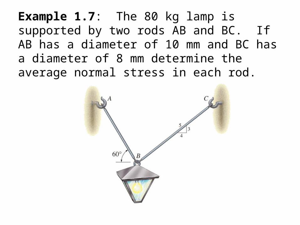
Example 1.7: The 80 kg lamp is supported by two rods AB and BC. If AB has a diameter of 10 mm and BC has a diameter of 8 mm determine the average normal stress in each rod.
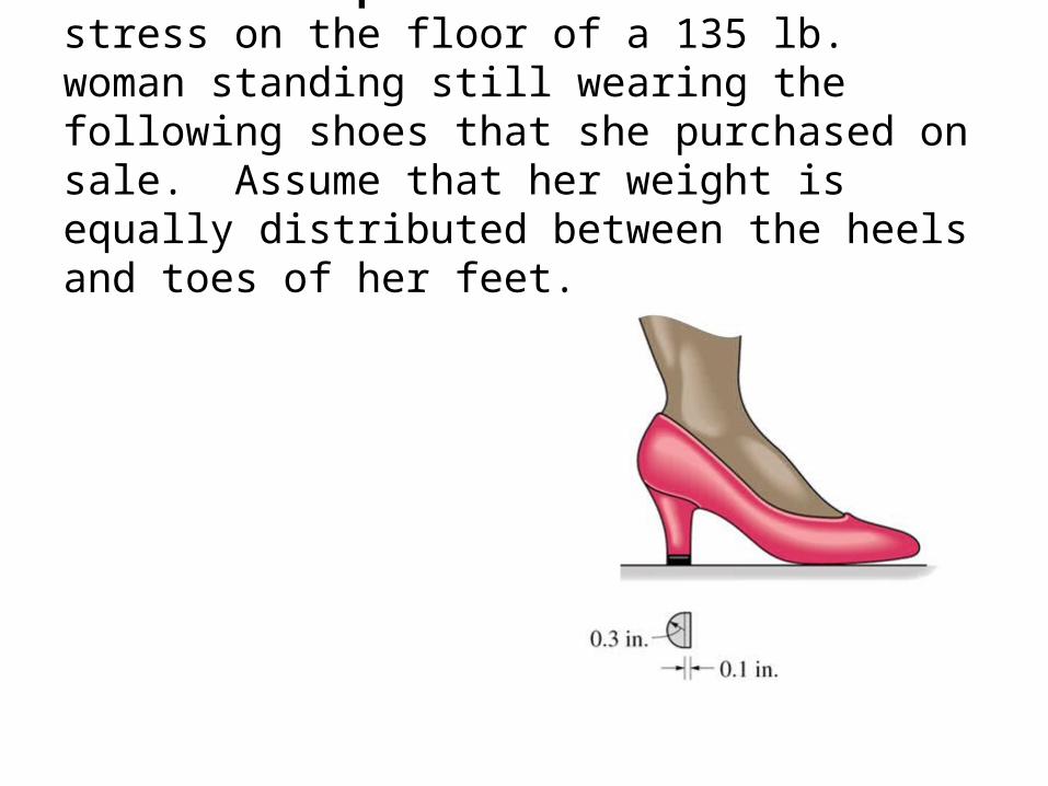
Lecture Example: Determine the stress on the floor of a 135 lb. woman standing still wearing the following shoes that she purchased on sale. Assume that her weight is equally distributed between the heels and toes of her feet.
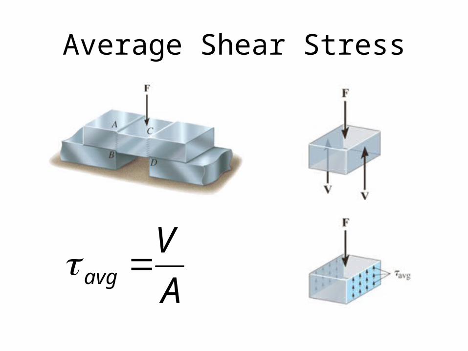
Average Shear Stress
A
Vavg
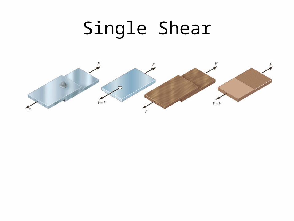
Single Shear
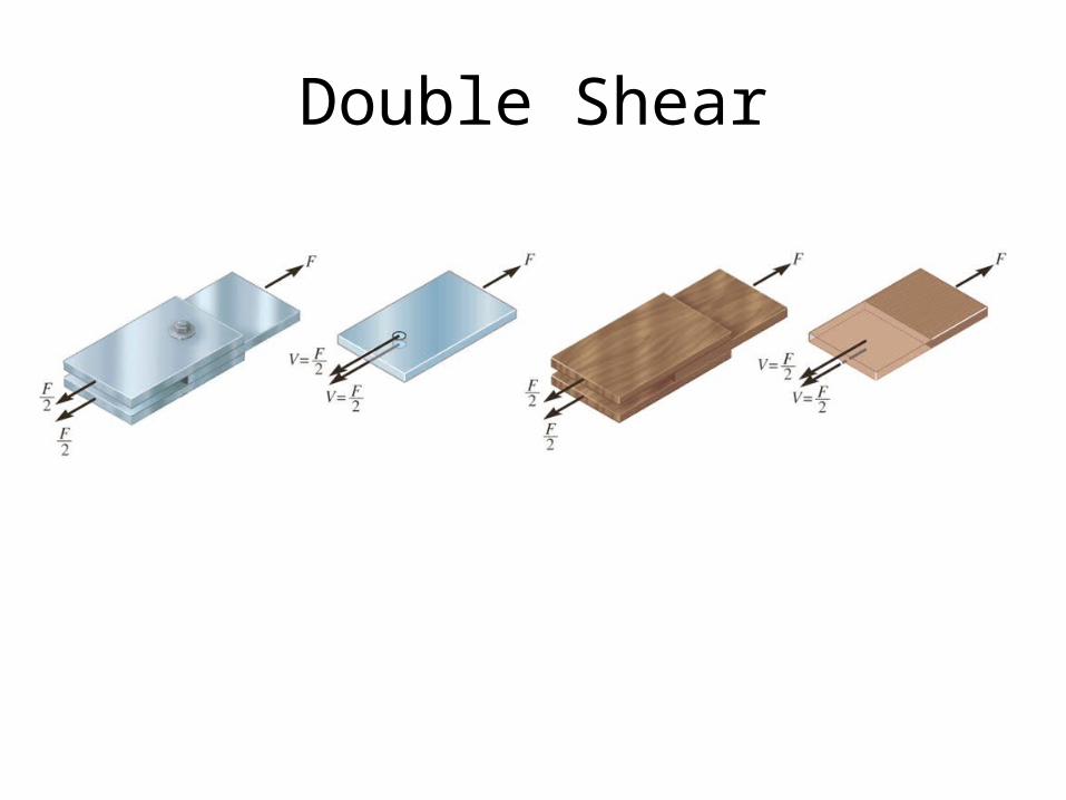
Double Shear
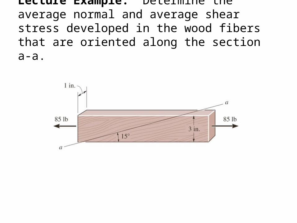
Lecture Example: Determine the average normal and average shear stress developed in the wood fibers that are oriented along the section a-a.
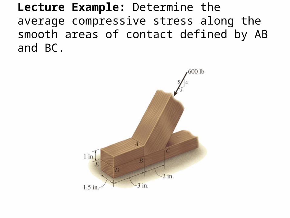
Lecture Example: Determine the average compressive stress along the smooth areas of contact defined by AB and BC.
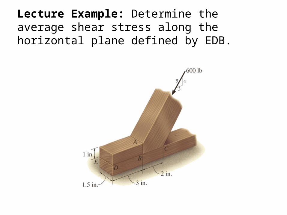
Lecture Example: Determine the average shear stress along the horizontal plane defined by EDB.
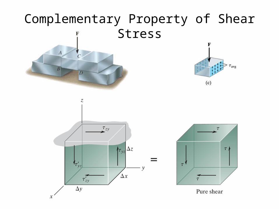
Complementary Property of Shear Stress
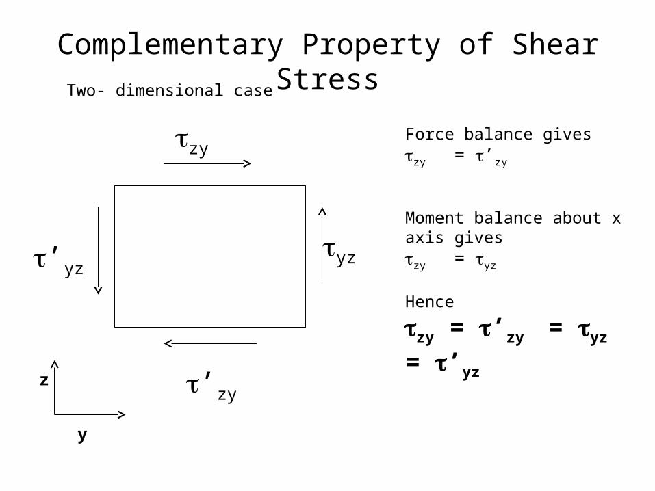
Complementary Property of Shear Stress
zy
yz
’zy
’yz
Force balance giveszy = ’zy
Moment balance about x axis giveszy = yz
Hence
zy = ’zy = yz = ’yz
Two- dimensional case
y
z
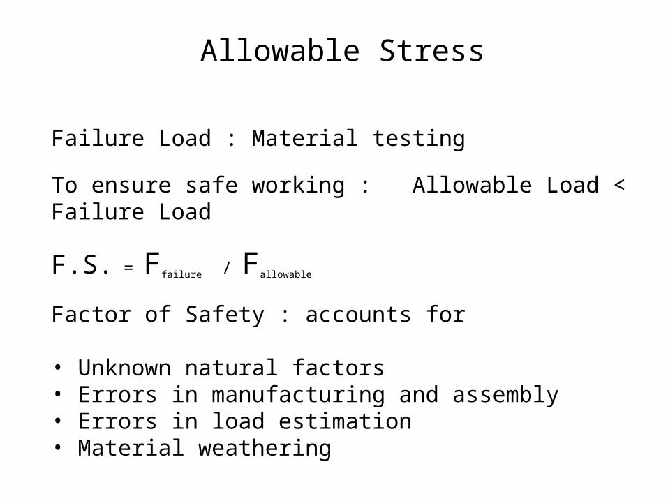
Allowable Stress
Failure Load : Material testing
To ensure safe working : Allowable Load < Failure Load
F.S. = Ffailure / Fallowable
Factor of Safety : accounts for
• Unknown natural factors • Errors in manufacturing and assembly• Errors in load estimation• Material weathering
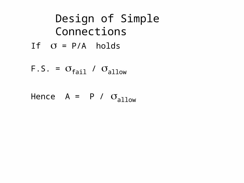
Design of Simple Connections
If = P/A holds
F.S. = fail / allow
Hence A = P / allow
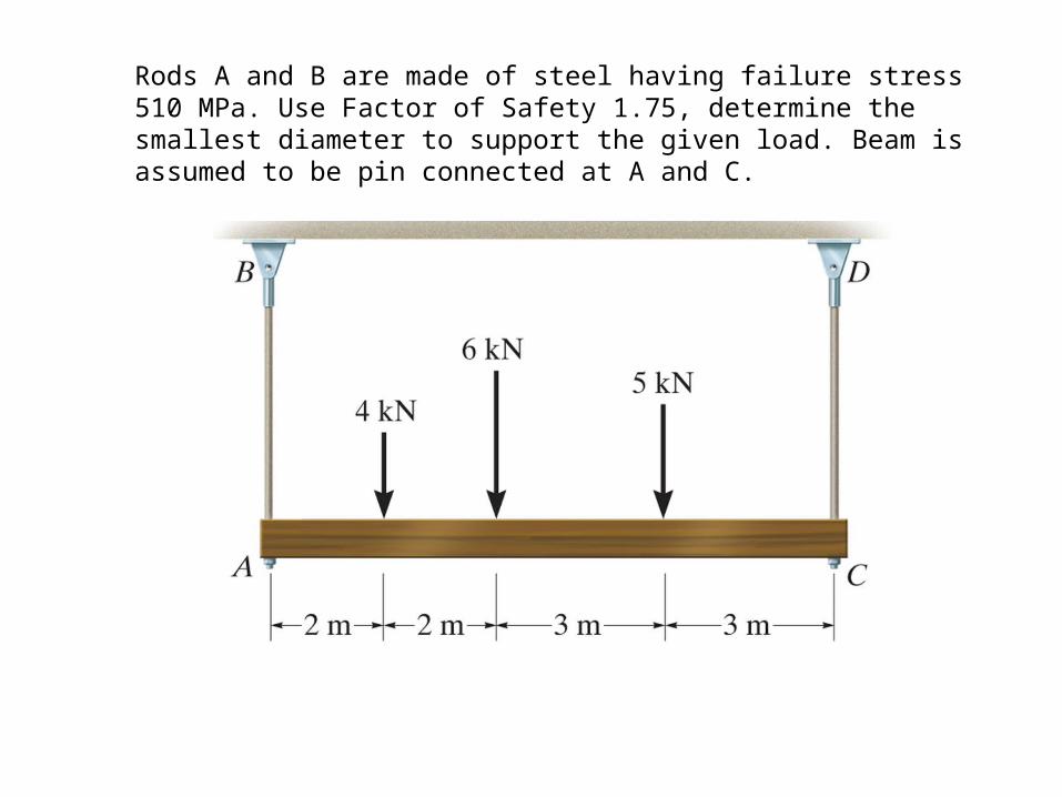
Rods A and B are made of steel having failure stress 510 MPa. Use Factor of Safety 1.75, determine the smallest diameter to support the given load. Beam is assumed to be pin connected at A and C.
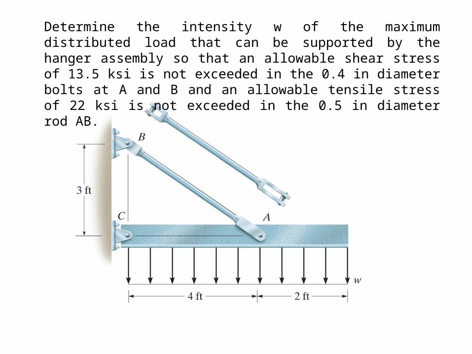
Determine the intensity w of the maximum distributed load that can be supported by the hanger assembly so that an allowable shear stress of 13.5 ksi is not exceeded in the 0.4 in diameter bolts at A and B and an allowable tensile stress of 22 ksi is not exceeded in the 0.5 in diameter rod AB.