Energy Output Through EAF Off-Gas Modelling the …eccc.c-s-m.it/uploaded_files/attachments/...2 of...
20
1 of 20 Energy Output Through EAF Off-Gas – Modelling the EAF Off-Gas System VALEAF workshop, Aachen, 23.04.2015 Thomas Meier – RWTH Aachen
Transcript of Energy Output Through EAF Off-Gas Modelling the …eccc.c-s-m.it/uploaded_files/attachments/...2 of...
1 of 20
Energy Output Through EAF Off-Gas
–
Modelling the EAF Off-Gas System
VALEAF workshop, Aachen, 23.04.2015
Thomas Meier – RWTH Aachen
2 of 20
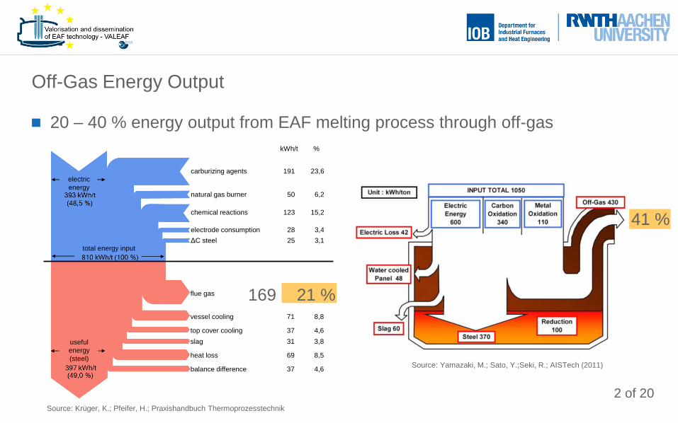
20 – 40 % energy output from EAF melting process through off-gas
Off-Gas Energy Output
kWh/t %
carburizing agents 191 23,6
natural gas burner 50 6,2
chemical reactions 123 15,2
electrode consumption 28 3,4
ΔC steel 25 3,1
flue gas 169 20,7
vessel cooling 71 8,8
top cover cooling 37 4,6
slag 31 3,8
heat loss 69 8,5
balance difference 37 4,6
electric
energy
total energy input
useful
energy
(steel)
Source: Krüger, K.; Pfeifer, H.; Praxishandbuch Thermoprozesstechnik
169 21 %
41 %
Source: Yamazaki, M.; Sato, Y.;Seki, R.; AISTech (2011)
3 of 20
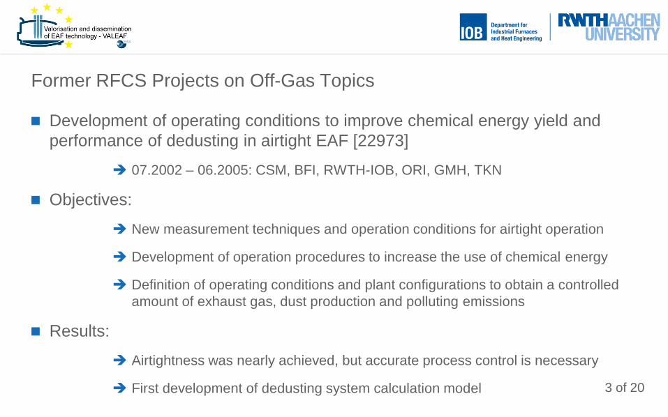
Development of operating conditions to improve chemical energy yield and
performance of dedusting in airtight EAF [22973]
07.2002 – 06.2005: CSM, BFI, RWTH-IOB, ORI, GMH, TKN
Objectives:
New measurement techniques and operation conditions for airtight operation
Development of operation procedures to increase the use of chemical energy
Definition of operating conditions and plant configurations to obtain a controlled
amount of exhaust gas, dust production and polluting emissions
Results:
Airtightness was nearly achieved, but accurate process control is necessary
First development of dedusting system calculation model
Former RFCS Projects on Off-Gas Topics
4 of 20
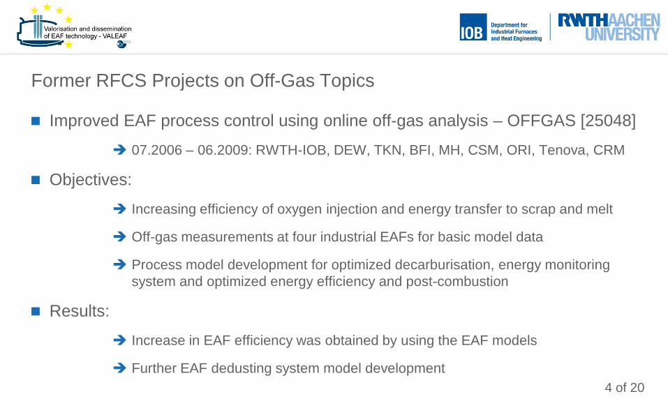
Improved EAF process control using online off-gas analysis – OFFGAS [25048]
07.2006 – 06.2009: RWTH-IOB, DEW, TKN, BFI, MH, CSM, ORI, Tenova, CRM
Objectives:
Increasing efficiency of oxygen injection and energy transfer to scrap and melt
Off-gas measurements at four industrial EAFs for basic model data
Process model development for optimized decarburisation, energy monitoring
system and optimized energy efficiency and post-combustion
Results:
Increase in EAF efficiency was obtained by using the EAF models
Further EAF dedusting system model development
Former RFCS Projects on Off-Gas Topics
5 of 20
Increasing energy costs and statutory provisions or incentives leading to
increased offers and interest in process control through off-gas measurements
and waste heat recovery from EAF off-gas
Further investigation of off-gas related questions necessary
Optimising the EAF melting process and the EAF control
Prediction of waste heat recovery potential and its optimisation
Optimised plant design and operator assistance
Therefore:
Connection of EAF process simulation model with model of dedusting system
EAF and Dedusting System Modelling
6 of 20
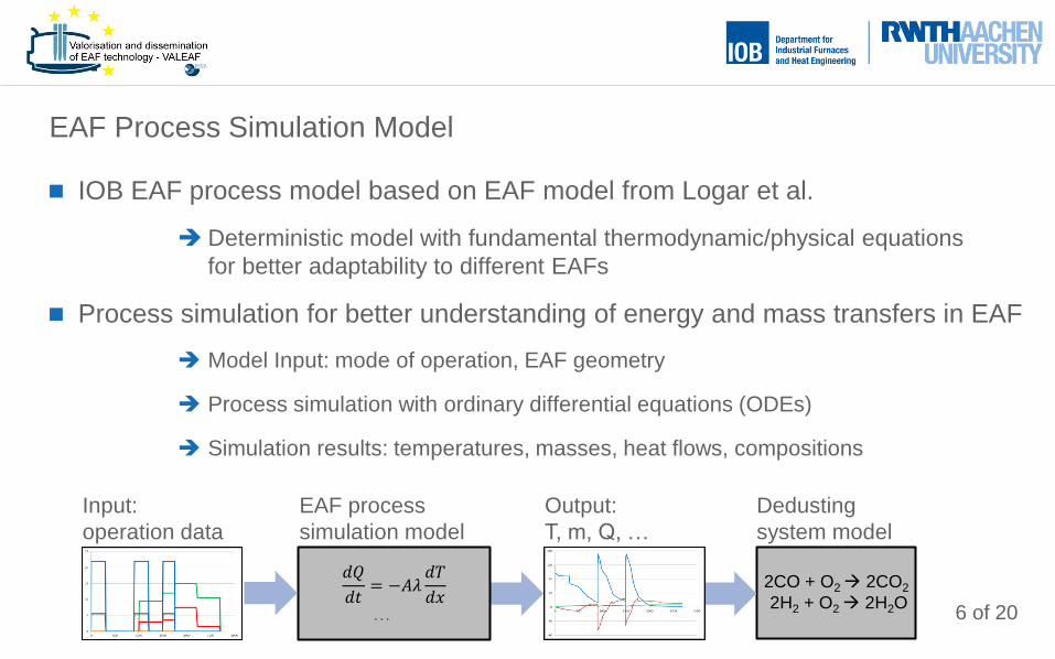
IOB EAF process model based on EAF model from Logar et al.
Deterministic model with fundamental thermodynamic/physical equations
for better adaptability to different EAFs
Process simulation for better understanding of energy and mass transfers in EAF
Model Input: mode of operation, EAF geometry
Process simulation with ordinary differential equations (ODEs)
Simulation results: temperatures, masses, heat flows, compositions
EAF Process Simulation Model
𝑑𝑄
𝑑𝑡= −𝐴𝜆
𝑑𝑇
𝑑𝑥
…
Output:
T, m, Q, …
Input:
operation data
EAF process
simulation model
Dedusting
system model
2CO + O2 2CO2
2H2 + O2 2H2O
7 of 20
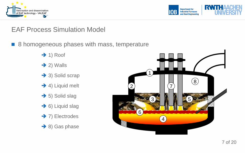
8 homogeneous phases with mass, temperature
1) Roof
2) Walls
3) Solid scrap
4) Liquid melt
5) Solid slag
6) Liquid slag
7) Electrodes
8) Gas phase
EAF Process Simulation Model
2
1
2
3
8
5
6
7
4
8 of 20
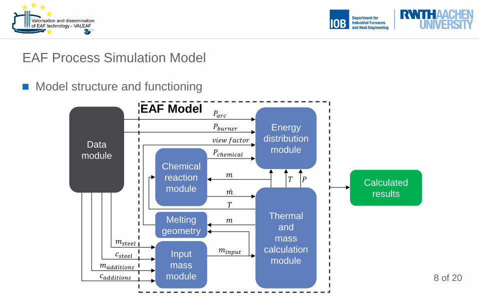
Model structure and functioning
EAF Process Simulation Model
Data
module
Energy
distribution
module
Chemical
reaction
module
Input
mass
module
Thermal
and
mass
calculation
module
Calculated
results
𝑚𝑠𝑡𝑒𝑒𝑙
𝑐𝑠𝑡𝑒𝑒𝑙
𝑚𝑎𝑑𝑑𝑖𝑡𝑖𝑜𝑛𝑠
𝑐𝑎𝑑𝑑𝑖𝑡𝑖𝑜𝑛𝑠
𝑚𝑖𝑛𝑝𝑢𝑡
𝑇
𝑚
𝑇 𝑃
𝑃𝑎𝑟𝑐
𝑃𝑏𝑢𝑟𝑛𝑒𝑟
𝑃𝑐ℎ𝑒𝑚𝑖𝑐𝑎𝑙
𝑚
EAF Model
Melting
geometry
𝑚
𝑣𝑖𝑒𝑤 𝑓𝑎𝑐𝑡𝑜𝑟
9 of 20
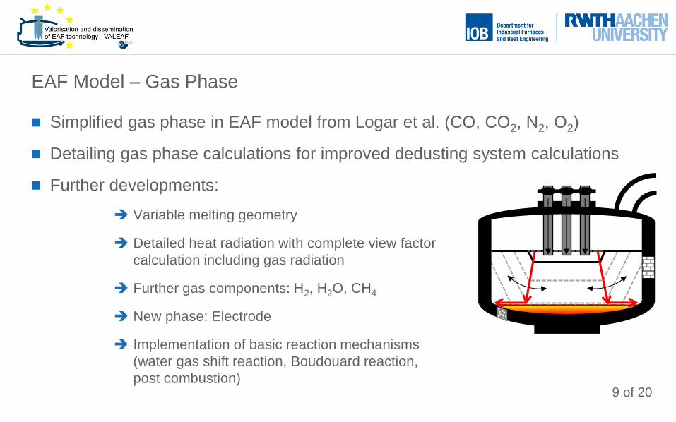
Simplified gas phase in EAF model from Logar et al. (CO, CO2, N2, O2)
Detailing gas phase calculations for improved dedusting system calculations
Further developments:
Variable melting geometry
Detailed heat radiation with complete view factor
calculation including gas radiation
Further gas components: H2, H2O, CH4
New phase: Electrode
Implementation of basic reaction mechanisms
(water gas shift reaction, Boudouard reaction,
post combustion)
EAF Model – Gas Phase
10 of 20
0
200
400
600
800
1000
1200
1400
1600
1800
2000
0 500 1000 1500 2000 2500 3000
Tem
pe
ratu
re [
°C]
Time [s]
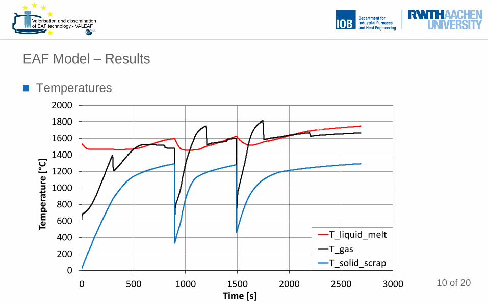
T_liquid_melt
T_gas
T_solid_scrap
Temperatures
EAF Model – Results
11 of 20 -80
-60
-40
-20
0
20
40
60
80
100
120
140
160
180
0 500 1000 1500 2000 2500 3000Po
we
r [M
W]
Time [s]
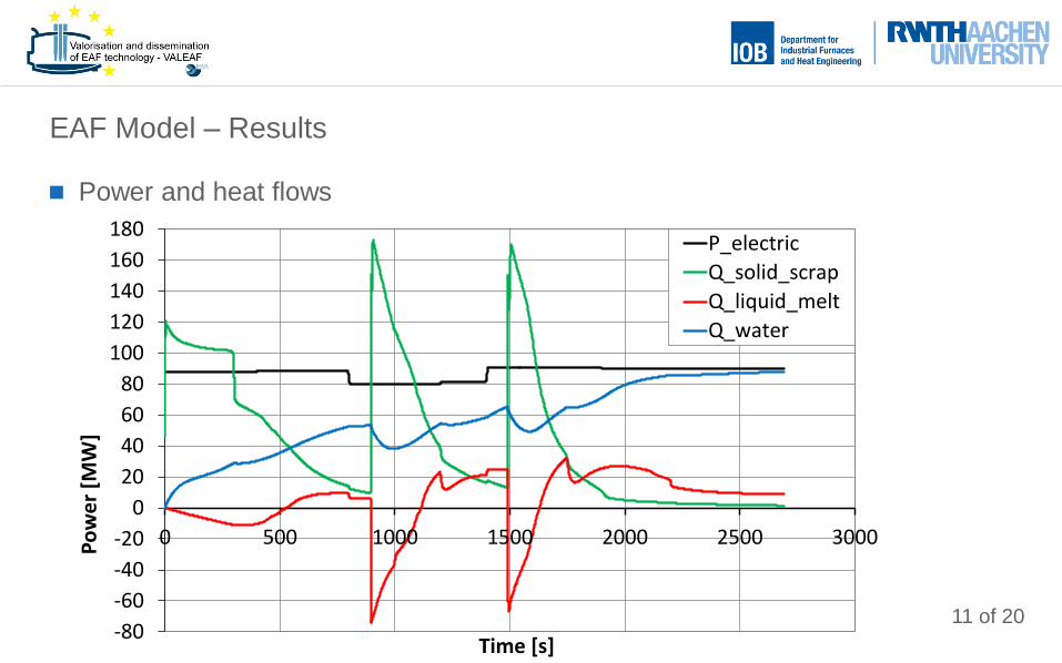
P_electric
Q_solid_scrap
Q_liquid_melt
Q_water
Power and heat flows
EAF Model – Results
12 of 20
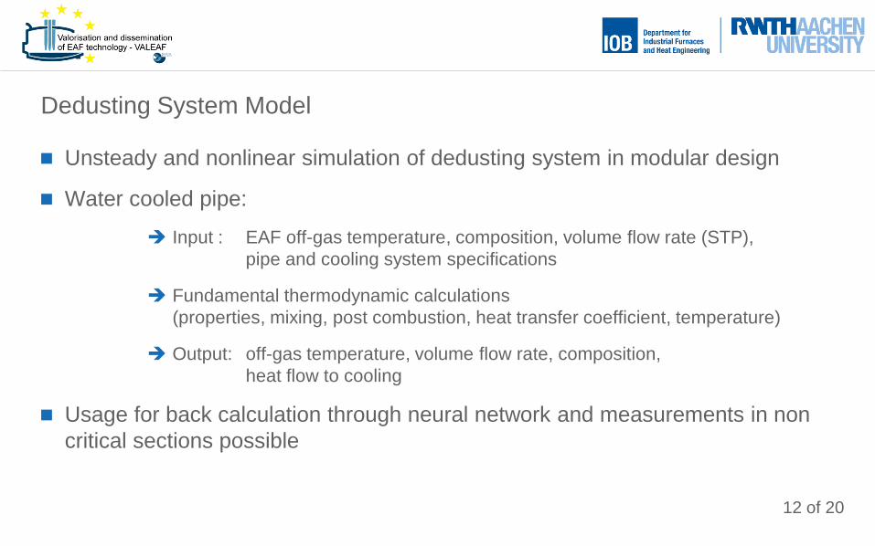
Unsteady and nonlinear simulation of dedusting system in modular design
Water cooled pipe:
Input : EAF off-gas temperature, composition, volume flow rate (STP),
pipe and cooling system specifications
Fundamental thermodynamic calculations
(properties, mixing, post combustion, heat transfer coefficient, temperature)
Output: off-gas temperature, volume flow rate, composition,
heat flow to cooling
Usage for back calculation through neural network and measurements in non
critical sections possible
Dedusting System Model
13 of 20
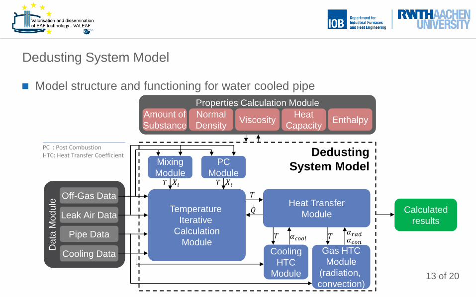
Model structure and functioning for water cooled pipe
Dedusting System Model
Temperature
Iterative
Calculation
Module
Properties Calculation Module
Amount of
Substance
Normal
Density Viscosity
Heat
Capacity Enthalpy
Mixing
Module
PC
Module
Heat Transfer
Module
Gas HTC
Module
(radiation,
convection)
Cooling
HTC
Module
PC : Post Combustion HTC: Heat Transfer Coefficient
Calculated
results
Dedusting
System Model
𝑄
𝑇
𝛼𝑐𝑜𝑜𝑙 𝑇 𝛼𝑟𝑎𝑑
Da
ta M
od
ule
Off-Gas Data
Cooling Data
Leak Air Data
Pipe Data 𝑇 𝛼𝑐𝑜𝑛
𝑇 𝑋𝑖 𝑇 𝑋𝑖
14 of 20
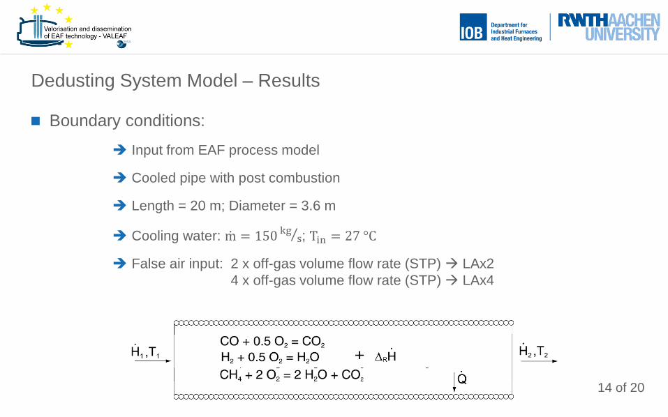
Boundary conditions:
Input from EAF process model
Cooled pipe with post combustion
Length = 20 m; Diameter = 3.6 m
Cooling water: m = 150 kgs ; Tin = 27 °C
False air input: 2 x off-gas volume flow rate (STP) LAx2
4 x off-gas volume flow rate (STP) LAx4
Dedusting System Model – Results
15 of 20
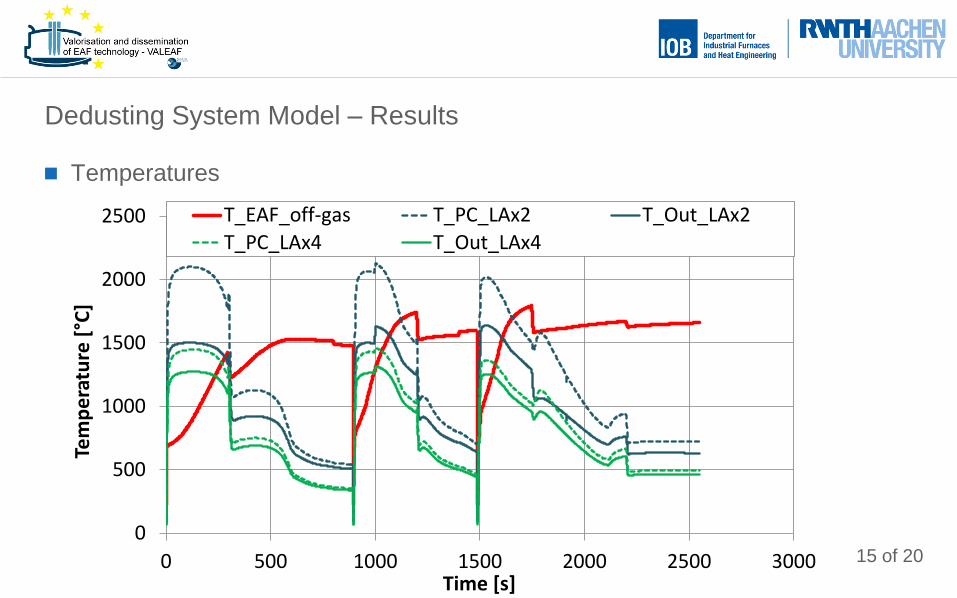
Temperatures
Dedusting System Model – Results
0
500
1000
1500
2000
2500
0 500 1000 1500 2000 2500 3000
Tem
pe
ratu
re [
°C]
Time [s]
T
T_EAF_off-gas T_PC_LAx2 T_Out_LAx2
T_PC_LAx4 T_Out_LAx4
16 of 20
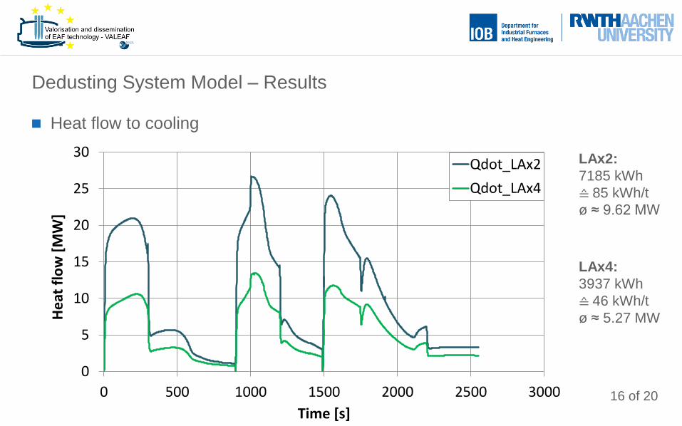
Heat flow to cooling
Dedusting System Model – Results
0
5
10
15
20
25
30
0 500 1000 1500 2000 2500 3000
He
at f
low
[M
W]
Time [s]
Qdot
Qdot_LAx2
Qdot_LAx4
LAx2:
7185 kWh
≙ 85 kWh/t
ø ≈ 9.62 MW
LAx4:
3937 kWh
≙ 46 kWh/t
ø ≈ 5.27 MW
17 of 20
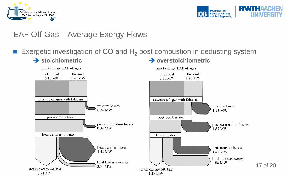
Exergetic investigation of CO and H2 post combustion in dedusting system
stoichiometric overstoichiometric
EAF Off-Gas – Average Exergy Flows
18 of 20
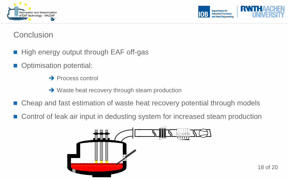
High energy output through EAF off-gas
Optimisation potential:
Process control
Waste heat recovery through steam production
Cheap and fast estimation of waste heat recovery potential through models
Control of leak air input in dedusting system for increased steam production
Conclusion
19 of 20
Further EAF process simulation model development:
Gas phase reactions via equilibrium with Gibbs energy minimisation
Model validation
Further dedusting system model development:
GUI for better usability
Steam generation
Model validation
Neural network utilisation for off-gas back calculation
Model interface between both models
Prospects
20 of 20
Contact:
Thomas Meier
RWTH Aachen University
Department for Industrial Furnaces and Heat Engineering
Kopernikusstraße 10
52074 Aachen
Germany
www.iob.rwth-aachen.de