EncapsulationofDiclofenacMoleculesintoPoly(ε … · EncapsulationofDiclofenacMoleculesintoPoly ......
9
Hindawi Publishing Corporation Journal of Nanomaterials Volume 2009, Article ID 238206, 8 pages doi:10.1155/2009/238206 Research Article Encapsulation of Diclofenac Molecules into Poly(ε-Caprolactone) Electrospun Fibers for Delivery Protection Loredana Tammaro, Giuseppina Russo, and Vittoria Vittoria Department of Chemical and Food Engineering, University of Salerno, Via Ponte Don Melillo, 84084 Fisciano, Italy Correspondence should be addressed to Vittoria Vittoria, [email protected] Received 16 June 2009; Accepted 22 September 2009 Recommended by David Hui Mg-Al Hydrotalcite-like clay (LDH) intercalated with diclofenac anions (HTlc-DIC) was introduced into poly(ε-caprolactone) (PCL) in different concentrations by the electrospinning technique, and mats of nonwoven fibers were obtained and compared to the pristine pure electrospun PCL. The fibers, characterized by X-ray diffraction, thermogravimetric analysis, and differential scanning calorimetry, show an exfoliated clay structure up to 3 wt%, a good thermal stability of the diclofenac molecules and a crystallinity of PCL comparable to the pure polymer. The scanning electron microscopy revealed electrospun PCL and PCL composite fibers diameters ranging between 500 nm to 3.0 μm and a generally uniform thickness along the fibers. As the results suggested the in vitro drug release from the composite fibers is remarkably slower than the release from the corresponding control spun solutions of PCL and diclofenac sodium salt. Thus, HTlc-DIC/PCL fibrous membranes can be used as an antinflammatory scaffold for tissue engineering. Copyright © 2009 Loredana Tammaro et al. This is an open access article distributed under the Creative Commons Attribution License, which permits unrestricted use, distribution, and reproduction in any medium, provided the original work is properly cited. 1. Introduction A challenge to the field of biomedical applications, and in particular of tissue engineering, is currently the design of synthetic matrices that can mimic the structure and biological functions of the natural extracellular matrix (ECM). Human cells can attach and organize well around fibers with suitable diameters. In this regard, nanoscale fibrous scaffolds can provide an optimal template for cells to seed, migrate, and grow. The utilization of biomaterials— both natural and synthetic—is enabling to develop scaffolds specifically designed for many medical applications [1–8]. The production methods for preparing such devices are wide ranging, and each method has its unique characteristics. Of particular interest in tissue engineering is the creation of reproducible and biocompatible three-dimensional scaffolds resulting in biomatrix composites useful for various appli- cations, as medical prostheses, wound dressing, and tissue template. In each specific application the ability to shape materials on different length scales, including the nanoscale, is of the utmost importance. Recently electrospinning, able to produce nonwoven membranes of nanofibres, characterized by a high surface-to- volume ratio, has been demonstrated as a successful means of producing scaffolds having many of the desirable and controllable properties. It is applicable to a wide variety of polymers and composite polymers, both natural and synthetic. In this technique polymer nanofibers are produced from an electrostatically driven jet of polymer solution or melt. The discharged polymer solution jet undergoes a whipping process wherein the solvent evaporates and the highly stretched polymer fiber deposits on a grounded target. A number of experimental parameters control the fiber diameter and morphology. The nanofibers, with diameters ranging from microns down to hundreds of nanometers or less, can be fabricated into a variety of forms such as membranes, coatings, and films and therefore can be used in several applications [9–15]. Linear aliphatic polyesters such as polyglicolide (PGA), polylactide (PLA), polycaprolactone (PCL), as well as their copolymers, are more and more often used as the base materials for tissue engineering [16]. These materials meet several controlled release criteria; that is, they are biocom- patible and biodegradable, beside they can provide high efficiency of drug loading. The release profiles of entrapped drugs can be finely tuned by controlling the degradation
-
Upload
nguyenkien -
Category
Documents
-
view
217 -
download
1
Transcript of EncapsulationofDiclofenacMoleculesintoPoly(ε … · EncapsulationofDiclofenacMoleculesintoPoly ......
Hindawi Publishing CorporationJournal of NanomaterialsVolume 2009, Article ID 238206, 8 pagesdoi:10.1155/2009/238206
Research Article
Encapsulation of Diclofenac Molecules into Poly(ε-Caprolactone)Electrospun Fibers for Delivery Protection
Loredana Tammaro, Giuseppina Russo, and Vittoria Vittoria
Department of Chemical and Food Engineering, University of Salerno, Via Ponte Don Melillo, 84084 Fisciano, Italy
Correspondence should be addressed to Vittoria Vittoria, [email protected]
Received 16 June 2009; Accepted 22 September 2009
Recommended by David Hui
Mg-Al Hydrotalcite-like clay (LDH) intercalated with diclofenac anions (HTlc-DIC) was introduced into poly(ε-caprolactone)(PCL) in different concentrations by the electrospinning technique, and mats of nonwoven fibers were obtained and comparedto the pristine pure electrospun PCL. The fibers, characterized by X-ray diffraction, thermogravimetric analysis, and differentialscanning calorimetry, show an exfoliated clay structure up to 3 wt%, a good thermal stability of the diclofenac molecules anda crystallinity of PCL comparable to the pure polymer. The scanning electron microscopy revealed electrospun PCL and PCLcomposite fibers diameters ranging between 500 nm to 3.0 μm and a generally uniform thickness along the fibers. As the resultssuggested the in vitro drug release from the composite fibers is remarkably slower than the release from the corresponding controlspun solutions of PCL and diclofenac sodium salt. Thus, HTlc-DIC/PCL fibrous membranes can be used as an antinflammatoryscaffold for tissue engineering.
Copyright © 2009 Loredana Tammaro et al. This is an open access article distributed under the Creative Commons AttributionLicense, which permits unrestricted use, distribution, and reproduction in any medium, provided the original work is properlycited.
1. Introduction
A challenge to the field of biomedical applications, andin particular of tissue engineering, is currently the designof synthetic matrices that can mimic the structure andbiological functions of the natural extracellular matrix(ECM). Human cells can attach and organize well aroundfibers with suitable diameters. In this regard, nanoscalefibrous scaffolds can provide an optimal template for cellsto seed, migrate, and grow. The utilization of biomaterials—both natural and synthetic—is enabling to develop scaffoldsspecifically designed for many medical applications [1–8].The production methods for preparing such devices are wideranging, and each method has its unique characteristics. Ofparticular interest in tissue engineering is the creation ofreproducible and biocompatible three-dimensional scaffoldsresulting in biomatrix composites useful for various appli-cations, as medical prostheses, wound dressing, and tissuetemplate. In each specific application the ability to shapematerials on different length scales, including the nanoscale,is of the utmost importance.
Recently electrospinning, able to produce nonwovenmembranes of nanofibres, characterized by a high surface-to-
volume ratio, has been demonstrated as a successful meansof producing scaffolds having many of the desirable andcontrollable properties. It is applicable to a wide varietyof polymers and composite polymers, both natural andsynthetic. In this technique polymer nanofibers are producedfrom an electrostatically driven jet of polymer solutionor melt. The discharged polymer solution jet undergoes awhipping process wherein the solvent evaporates and thehighly stretched polymer fiber deposits on a grounded target.A number of experimental parameters control the fiberdiameter and morphology. The nanofibers, with diametersranging from microns down to hundreds of nanometersor less, can be fabricated into a variety of forms such asmembranes, coatings, and films and therefore can be usedin several applications [9–15].
Linear aliphatic polyesters such as polyglicolide (PGA),polylactide (PLA), polycaprolactone (PCL), as well as theircopolymers, are more and more often used as the basematerials for tissue engineering [16]. These materials meetseveral controlled release criteria; that is, they are biocom-patible and biodegradable, beside they can provide highefficiency of drug loading. The release profiles of entrappeddrugs can be finely tuned by controlling the degradation
2 Journal of Nanomaterials
rate of the polymer matrix through molecular weight anddistribution, material composition, and porosity of thecarriers. However, the successful encapsulation of watersoluble agents in these hydrophobic polymers still presentschallenges in high drug loading and avoiding their denatu-ration during the formulation process. Electrospun polymernanofibers have been designed for pharmaceutical com-positions either integrating the drug and carrier materialsinto one kind of fiber containing both components orelectrospinning the carrier material into a tubular formin which the drug particles are encapsulated. However apossible limit of these systems is a rapid release of thedrug, making it available for a too short period [17,18].
A more remarkable innovation in this field is cur-rently coming from nanoscience and nanotechnologies, thatare opening new opportunities for producing materialswith surprisingly unusual properties. The possibility tomanipulate at atomic or molecular level induces struc-tures having unique characteristics and completely newfunctionalities to be used not only as structural materialsbut also as smart structures for many fields as drugdelivery. Innovative composites can be obtained employinga suitable nanoscale or other fine scale architecture tocontrol the structural organization and, as a consequence,the physical and mechanical properties of the material.Nanoscale reinforcement has found widespread interest inthe macromolecular field, since polymer properties areremarkably improved when compared with virgin polymeror conventional microcomposites. On the other hand, a widerange of additives, including biologically active molecules,can be immobilized on the inorganic lamellae with ionicbonds. They can be successively released by exchangereactions with ions present in the solutions they are put incontact.
Recently a novel therapeutic delivery system based onmetal (II)-metal (III) layered double hydroxides (LDHs)or hydrotalcite-like compound (HTlc) was proposed. Inour case LDHs consist of brucite-like layers of magnesiumhydroxide, where some Mg(II) cations are isomorphicallysubstituted with Al(III) cations to confer net positive chargesto the layers. These charges are balanced by interlayeredhydrated anions, resulting in a multilayer of alternatinghost layers and gallery anions [19–21]. Using ion exchangereaction, many novel complexes may be synthesized, andactually anti-inflammatory, antibiotics, plant growth reg-ulators, and others have been incorporated into LDHs,obtaining nanohybrids that can slowly release the activemolecules [22–24].
In this study we present the preparation of new fibrouscomposites by using electrospinning technique, obtainedby fixing an anti-inflammatory drug, diclofenac sodium,into a lamellar inorganic compound, and incorporating theobtained nanohybrid into a biodegradable polycaprolactone.The structure, morphology, and thermal behavior of theelectrospun fibers were analyzed. The release of the activediclofenac molecules was found much slower in comparisonto the release of the fibers in which the drug was directlyincorporated into the polymer.
2. Experimental Procedures
2.1. Materials. The Mg-Al hydrotalcite-like compoundintercalated with anti-inflammatory drug, having formula[Mg0.60Al0.40(OH)2](DIC)0.28(NO3)0.12x1.05H2O, (HTlc-DIC), has been obtained according to a previously reportedprocedure [25–27].
Poly(ε-caprolactone) (PCL, Mn = 80000 Da), diclofenacsodium salt (DIC-Na), and acetone were purchased fromSigma-Aldrich.
2.2. Electrospinning of PCL, PCL/HTlc-DIC, and PCL/DIC-Na Fibers. PCL fibers were prepared by electrospinningof its solution in acetone (15 wt% PCL). PCL/HTlc-DICfibers with PCL/HTlc-DIC weight ratio of 90/10, 95/5, 97/3,and 99/1 were prepared by electrospinning of their mixedsolution in acetone (15 wt% total polymer concentration).These solutions were prepared by first dissolving the exactamount of PCL required to obtain the fully polymer solutionin acetone as the solvent. The filler HTlc-DIC was slowlyadded to the acetone polymer solution with vigorous stirringat 50◦C for 3 hours. After cooling at room temperature thesolutions were electrospun. Control acetone solutions wereprepared as previously described with the concentration ofPCL of 15 wt% and the concentration of DIC-Na rangingfrom 0.5 to 5 wt% respect to PCL.
Briefly, the electrospinning in a typical run was carriedout as follows. PCL, PCL/HTlc-DIC, and PCL/DIC-Nasolutions were placed in a glass syringe (5 mL) with acapillary tip diameter of 0.8 mm. A copper wire was mountedin the spinneret and used as the positive electrode. Theelectrode was connected to a variable high voltage powersupply purchased from Gamma High Voltage Research,Ormond, FL. The electrospinning was carried out at aconstant applied voltage (35 kV) and at a constant distancebetween the tip of the syringe and the collector (20 cm).For easy collecting of the electrospun mats, aluminum platesmeasuring 10 × 10 cm were placed on the collection screen.The electrospun samples were placed under vacuum for 72hours to remove any solvent residues. In the following thesamples will be named as PCL-HDICn and PCL-DICNan,where n is the amount of HTlc-DIC and DIC-Na present inthe composites, respectively.
The electrospinning conditions are summarized inTable 1.
2.3. Methods
Thermogravimetric Analysis (TG-DTA). Thermoanalyticalcharacterizations were performed with a Mettler TC-10thermobalance operating at 5◦C/min heating rate, under airflow, from 30◦C to 1000◦C. Degradation temperature (Td) isreported as the midpoint of the degradation step.
Differential Scanning Calorimetry (DSC). DSC measure-ments were carried out using a thermal analyzer MettlerDSC 822/400 instrument having subambient capability at aheating rate of 10◦C/min from −60◦C to 180◦C.
Journal of Nanomaterials 3
Table 1: The electrospinning conditions.
SampleSolvent Potential Distance Flow rate Concentration
(kV) (cm) (mL/h) (wt%)
PCL and all composites Acetone 35 20 3 15
0
10
20
30
40
50
60
70
80
90
100
Res
idu
alw
eigh
t(%
)
100 200 300 400 500 600 700 800 900 1000
Temperature (◦C)
HTIc-DIC
PCL
PCL-HDIC5
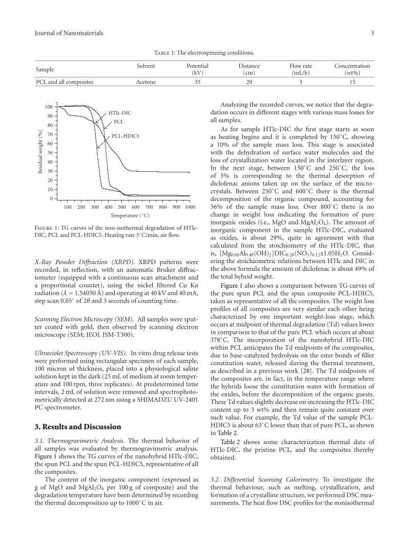
Figure 1: TG curves of the non-isothermal degradation of HTlc-DIC, PCL and PCL-HDIC5. Heating rate 5◦C/min, air flow.
X-Ray Powder Diffraction (XRPD). XRPD patterns wererecorded, in reflection, with an automatic Bruker diffrac-tometer (equipped with a continuous scan attachment anda proportional counter), using the nickel filtered Cu Kαradiation (λ = 1.54050 A) and operating at 40 kV and 40 mA,step scan 0.05◦ of 2θ and 3 seconds of counting time.
Scanning Electron Microscopy (SEM). All samples were sput-ter coated with gold, then observed by scanning electronmicroscope (SEM; JEOL JSM-T300).
Ultraviolet Spectroscopy (UV-VIS). In vitro drug release testswere performed using rectangular specimen of each sample,100 micron of thickness, placed into a physiological salinesolution kept in the dark (25 mL of medium at room temper-ature and 100 rpm, three replicates). At predetermined timeintervals, 2 mL of solution were removed and spectrophoto-metrically detected at 272 nm using a SHIMADZU UV-2401PC spectrometer.
3. Results and Discussion
3.1. Thermogravimetric Analysis. The thermal behavior ofall samples was evaluated by thermogravimetric analysis.Figure 1 shows the TG curves of the nanohybrid HTlc-DIC,the spun PCL and the spun PCL-HDIC5, representative of allthe composites.
The content of the inorganic component (expressed asg of MgO and MgAl2O4 per 100 g of composite) and thedegradation temperature have been determined by recordingthe thermal decomposition up to 1000◦C in air.
Analyzing the recorded curves, we notice that the degra-dation occurs in different stages with various mass losses forall samples.
As for sample HTlc-DIC the first stage starts as soonas heating begins and it is completed by 150◦C, showinga 10% of the sample mass loss. This stage is associatedwith the dehydration of surface water molecules and theloss of crystallization water located in the interlayer region.In the next stage, between 150◦C and 250◦C, the lossof 5% is corresponding to the thermal desorption ofdiclofenac anions taken up on the surface of the micro-crystals. Between 250◦C and 600◦C there is the thermaldecomposition of the organic compound, accounting for56% of the sample mass loss. Over 800◦C there is nochange in weight loss indicating the formation of pureinorganic oxides (i.e., MgO and MgAl2O4). The amount ofinorganic component in the sample HTlc-DIC, evaluatedas oxides, is about 29%, quite in agreement with thatcalculated from the stoichiometry of the HTlc-DIC, thatis, [Mg0.60Al0.40(OH)2]DIC0.28(NO3)0.12x1.05H2O. Consid-ering the stoichiometric relations between HTlc and DIC inthe above formula the amount of diclofenac is about 49% ofthe total hybrid weight.
Figure 1 also shows a comparison between TG curves ofthe pure spun PCL and the spun composite PCL-HDIC5,taken as representative of all the composites. The weight lossprofiles of all composites are very similar each other beingcharacterized by one important weight-loss stage, whichoccurs at midpoint of thermal degradation (Td) values lowerin comparison to that of the pure PCL which occurs at about378◦C. The incorporation of the nanohybrid HTlc-DICwithin PCL anticipates the Td midpoints of the composites,due to base-catalyzed hydrolysis on the ester bonds of fillerconstitution water, released during the thermal treatment,as described in a previous work [28]. The Td midpoints ofthe composites are, in fact, in the temperature range wherethe hybrids loose the constitution water with formation ofthe oxides, before the decomposition of the organic guests.These Td values slightly decrease on increasing the HTlc-DICcontent up to 3 wt% and then remain quite constant oversuch value. For example, the Td value of the sample PCL-HDIC5 is about 63◦C lower than that of pure PCL, as shownin Table 2.
Table 2 shows some characterization thermal data ofHTlc-DIC, the pristine PCL, and the composites therebyobtained.
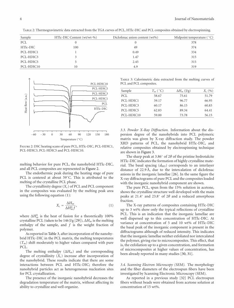
3.2. Differential Scanning Calorimetry. To investigate thethermal behaviour, such as melting, crystallization, andformation of a crystalline structure, we performed DSC mea-surements. The heat flow DSC profiles for the nonisothermal
4 Journal of Nanomaterials
Table 2: Thermogravimetric data extracted from the TGA curves of PCL, HTlc-DIC and PCL composites obtained by electrospinning.
Sample HTlc-DIC Content (wt/wt-%) Diclofenac anion content (wt%) Midpoint temperature ( ◦C)
PCL 0 0 378
HTlc-DIC 100 49 374
PCL-HDIC1 1 0.49 334
PCL-HDIC3 3 1.47 315
PCL-HDIC5 5 2.45 315
PCL-HDIC10 10 4.9 319
Hea
tfl
ow(a
.u.)
−60 −30 0 30 60 90 120 150 180
Temperature (◦C)
PCL-HDIC5
PCL-HDIC3
PCL-HDIC10
PCL-HDIC1
PCL
HTIc-DIC
Figure 2: DSC heating scans of pure PCL, HTlc-DIC, PCL-HDIC1,PCL-HDIC3, PCL-HDIC5 and PCL-HDIC10.
melting behavior for pure PCL, the nanohybrid HTlc-DIC,and all PCL composites are represented in Figure 2.
The endothermic peak during the heating stage of purePCL is centered at about 59◦C. This is attributed to themelting of the crystalline PCL phase.
The crystallinity degree (Xc) of PCL and PCL componentin the composites was evaluated by the melting peak areausing the following equation (1):
Xc = ΔHm
ΔH0m f
, (1)
where ΔH0m is the heat of fusion for a theoretically 100%
crystalline PCL (taken to be 146 J/g [29]), ΔHm is the meltingenthalpy of the sample, and f is the weight fraction ofpolymer.
As reported in Table 3, after incorporation of the nanohy-brid HTlc-DIC in the PCL matrix, the melting temperatures(Tm) shift moderately to higher values compared with purePCL.
The melting enthalpy (ΔHm) and the correspondingdegree of crystallinity (Xc) increase after incorporation ofthe nanohybrid. These results indicate that there are someinteractions between PCL and HTlc-DIC; therefore thenanohybrid particles act as heterogeneous nucleation sitesfor PCL crystallization.
The presence of the inorganic nanohybrid decreases thedegradation temperature of the matrix, without affecting itsability to crystallize and well organize.
Table 3: Calorimetric data extracted from the melting curves ofPCL and PCL composites.
Sample Tm ( ◦C) ΔHm (J/g) Xc (%)
PCL 58.67 75.61 51.79
PCL-HDIC1 59.17 96.77 66.95
PCL-HDIC3 60.17 86.15 60.83
PCL-HDIC5 62.83 89.34 64.41
PCL-HDIC10 59.00 73.78 56.15
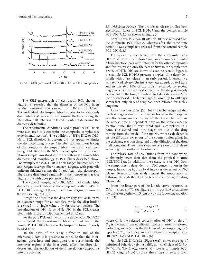
3.3. Powder X-Ray Diffraction. Information about the dis-persion degree of the nanohybrids into PCL polymericmatrix was given by X-ray diffraction study. The powderXRD patterns of PCL, the nanohybrid HTlc-DIC, andrelative composites obtained by electrospinning techniqueare shown in Figure 3.
The sharp peak at 3.86◦ of 2θ of the pristine hydrotalciteHTlc-DIC indicates the formation of highly crystalline mate-rial. The basal spacing (d003) corresponds to an interlayerdistance of 22.9 A, due to the intercalation of diclofenacanions in the inorganic lamellae [26]. In the same figure theX-ray diffractograms of pure PCL and the composites loadedwith the inorganic nanohybrid component are shown.
The pure PCL, spun from the 15% solution in acetone,shows the crystalline structure well developed with the mainpeaks at 21.4◦ and 23.8◦ of 2θ and a reduced amorphousfraction.
The X-ray patterns of composites containing HTlc-DICup to 3 wt% show only the typical reflections of crystallinePCL. This is an indication that the inorganic lamellae arewell dispersed up to this concentration of HTlc-DIC. Atvariance at concentration of 5 and 10 wt% of HTlc-DICthe basal peak of the inorganic component is present in thediffractograms although of reduced intensity. This indicatesthat the inorganic lamellae neither exfoliated nor intercalatedthe polymer, giving rise to microcomposites. This effect, thatis, the exfoliation up to a given concentration, and formationof microcomposites at higher values of concentration, hasbeen already reported in many studies [30, 31].
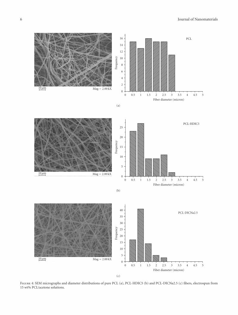
3.4. Scanning Electron Microscopy (SEM). The morphologyand the fiber diameters of the electrospun fibers have beeninvestigated by Scanning Electronic Microscopy (SEM).
As reported in a previous study [32] PCL electrospunfibers without beads were obtained from acetone solution atconcentration of 15 wt%.
Journal of Nanomaterials 5
Inte
nsi
ty(a
.u.)
5 10 15 20 25 30 35
2θ (deg)
PCL-HDIC10
PCL-HDIC5
PCL-HDIC3
PCL-HDIC1
PCL
HTIc-DIC
Figure 3: XRD patterns of: HTlc-DIC, PCL and PCL composites.
The SEM micrograph of electrospun PCL shown inFigure 4(a) revealed that the diameter of the PCL fibersin the nonwoven mat ranged from 500 nm to 3.0 μm.The individual electrospun fibers appear to be randomlydistributed and generally had similar thickness along thefiber. About 100 fibers were tested in order to determine thediameter distribution.
The experimental conditions used to produce PCL fiberswere also used to electrospin the composite samples (seeexperimental section). The addition of HTlc-DIC or DIC-Na to PCL dissolved in acetone did not appear to hinderthe electrospinning process. The fiber diameter morphologyof the composite electrospun fibers was again examinedusing SEM. Based on the SEM micrographs for the differentfibrous samples investigated, the fibers showed a similar fiberdiameter and morphology to PCL fibers described above.For example, the PCL-HDIC5 fibers ranged between 500 nmand 3.0 μm (average fiber diameter, 1.0 μm), with generallyuniform thickness along the fibers. Again the electrospunfibers were distributed randomly in the nonwoven mat (seeFigure 4(b)) with poor presence of beads.
The control sample, PCL-DICNa2.5, had similar fiberdiameter characteristics of the composite with 5 wt% ofHTlc-DIC: average 1.0 μm; maximum 2.5 μm; minimum0.5 μm (see Figure 4(c)).
It might be noted that the data are very similar in termsof diameter range for all samples, while the distributionis centred in a single value only for the composites. Theintroduction of DIC-Na or HTlc-DIC in the PCL createsfibers with similar distribution centred in 1.0 μm.
For the pure PCL and the control sample PCL-DICNa2.5we observed the formation of fibers without beads; thesample PCL-HDIC5 has been electrospun in form of poorlybeaded fibers.
On the basis of the x-ray diffraction and of themicroscopy data it is possible to conclude that the inter-actions guest-host and guest-guest that occur inside theinterlayer region of the filler could affect the dispersiondegree and the exfoliation of the intercalation compoundsinto the polymer.
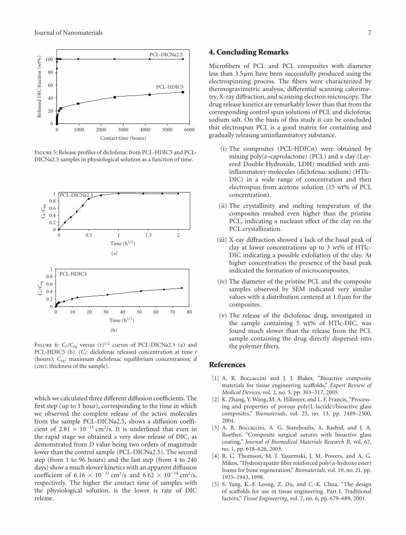
3.5. Diclofenac Release. The diclofenac release profiles fromelectrospun fibers of PCL-HDIC5 and the control samplePCL-DICNa2.5 are shown in Figure 5.
After 1 hour, less than 10 wt% of DIC was released fromthe composite PCL-HDIC5, whereas after the same timeperiod it was completely released from the control samplePCL-DICNa2.5.
The release of diclofenac from the composite PCL-HDIC5 is both much slower and more complex. Similarrelease kinetic curves were obtained for the other compositesand for this reason only the data relative to the sample with5 wt% of HTlc-DIC are shown. As can be seen in Figure 5,the sample PCL-HDIC5 presents a typical time-dependentprofile with a fast release in an early period, followed by avery reduced release. The first step stage extends up to 1 hourand in this step 10% of the drug is released; the secondstage, in which the released content of the drug is linearlydependent on the time, extends up to 4 days showing 20% ofthe drug released. The latter stage, followed up to 240 days,shows that only 50% of drug had been released for such along time.
As in previous cases [23, 26] it can be suggested thatthe first stage is due to the drug anchored in the inorganiclamellae laying on the surface of the fibers. In this casethe release time is dependent only on the ionic exchangereaction time, that is very rapid and is completed in 1hour. The second and third stages are due to the drugcoming from the inside of the matrix, whose exit dependson the diffusion behaviour of the counter-anion going in,the exchange reaction time, and on the diffusion of the drugitself going out. These three steps are very slow and a releaseextending for months can be observed.
The release rate of DIC anions from the nanohybridis obviously lower than that from the physical mixture(PCL/DIC-Na). In addition, the release rate of DIC fromthe composites is dependent on DIC concentration in thesample. Increasing in drug load increases the extent of DICrelease. Results of this study suggest the importance ofdiffusion through the LDH particle in controlling the drugrelease rate.
From the linear part of the kinetic curve (reported asCt/Ceq versus (t)1/2), see Figure 6, it is possible to calculatethe diffusion coefficient D (cm2/s) by the following equation(2) [33]:
CtCeq
= 4d
(Dt
π
)1/2
, (2)
where Ct is the released concentration of DIC at time t,Ceq is the maximum equilibrium concentration of releasedmolecules, and d (cm) is the thickness of the sample. Figure 6reports Ct/Ceq versus square root of time for samples PCL-DICNa2.5 (a) and PCL-HDIC5 (b).
Sample PCL-DICNa2.5 (Figure 6(a)) shows one step ofdiffusional behaviour giving a diffusion coefficient of 2.15 ×10⁻⁹ cm2/s. The Ct/Ceq versus (t)1/2 curve of sample PCL-HDIC5 (Figure 6(b)) displays three steps of release from
6 Journal of Nanomaterials
0
2
4
6
8
10
12
14
16
Freq
uen
cy
0 0.5 1 1.5 2 2.5 3 3.5 4 4.5 5
Fiber diameter (micron)
10μm Mag = 2.00 kX
PCL
(a)
0
5
10
15
20
25
Freq
uen
cy
0 0.5 1 1.5 2 2.5 3 3.5 4 4.5 5
Fiber diameter (micron)
10μm Mag = 2.00 kX
PCL-HDIC5
(b)
0
5
10
15
20
25
30
35
40
Freq
uen
cy
0 0.5 1 1.5 2 2.5 3 3.5 4 4.5 5
Fiber diameter (micron)
10μm Mag = 2.00 kX
PCL-DICNa2.5
(c)
Figure 4: SEM micrographs and diameter distributions of pure PCL (a), PCL-HDIC5 (b) and PCL-DICNa2.5 (c) fibers, electrospun from15 wt% PCL/acetone solutions.
Journal of Nanomaterials 7
0
20
40
60
80
100
Rel
ease
dD
ICfr
acti
on(w
t%)
0 1000 2000 3000 4000 5000 6000
Contact time (hours)
PCL-DICNa2.5
PCL-HDIC5
Figure 5: Release profiles of diclofenac from PCL-HDIC5 and PCL-DICNa2.5 samples in physiological solution as a function of time.
0
0.20.40.6
0.8
1
Ct/C
eq
0 0.5 1 1.5 2
Time (h1/2)
PCL-DICNa2.5
(a)
0
0.2
0.4
0.6
0.8
1
Ct/C
eq
0 10 20 30 40 50 60 70 80
Time (h1/2)
PCL-HDIC5
(b)
Figure 6: Ct/Ceq versus (t)1/2 curves of PCL-DICNa2.5 (a) andPCL-HDIC5 (b). (Ct : diclofenac released concentration at time t(hours); Ceq: maximum diclofenac equilibrium concentration; d(cm): thickness of the sample).
which we calculated three different diffusion coefficients. Thefirst step (up to 1 hour), corresponding to the time in whichwe observed the complete release of the active moleculesfrom the sample PCL-DICNa2.5, shows a diffusion coeffi-cient of 2.81 × 10⁻¹¹ cm2/s. It is underlined that even inthe rapid stage we obtained a very slow release of DIC, asdemonstrated from D value being two orders of magnitudelower than the control sample (PCL-DICNa2.5). The secondstep (from 1 to 96 hours) and the last step (from 4 to 240days) show a much slower kinetics with an apparent diffusioncoefficient of 6.16 × 10⁻¹³ cm2/s and 6.62 × 10⁻¹⁴ cm2/s,respectively. The higher the contact time of samples withthe physiological solution, is the lower is rate of DICrelease.
4. Concluding Remarks
Microfibers of PCL and PCL composites with diameterless than 3.5 μm have been successfully produced using theelectrospinning process. The fibers were characterized bythermogravimetric analysis, differential scanning calorime-try, X-ray diffraction, and scanning electron microscopy. Thedrug release kinetics are remarkably lower than that from thecorresponding control spun solutions of PCL and diclofenacsodium salt. On the basis of this study it can be concludedthat electrospun PCL is a good matrix for containing andgradually releasing antinflammatory substance.
(i) The composites (PCL-HDICn) were obtained bymixing poly(ε–caprolactone) (PCL) and a clay (Lay-ered Double Hydroxide, LDH) modified with anti-inflammatory molecules (diclofenac sodium) (HTlc-DIC) in a wide range of concentration and thenelectrospun from acetone solution (15 wt% of PCLconcentration).
(ii) The crystallinity and melting temperature of thecomposites resulted even higher than the pristinePCL, indicating a nucleant effect of the clay on thePCL crystallization.
(iii) X-ray diffraction showed a lack of the basal peak ofclay at lower concentrations up to 3 wt% of HTlc-DIC indicating a possible exfoliation of the clay. Athigher concentration the presence of the basal peakindicated the formation of microcomposites.
(iv) The diameter of the pristine PCL and the compositesamples observed by SEM indicated very similarvalues with a distribution centered at 1.0 μm for thecomposites.
(v) The release of the diclofenac drug, investigated inthe sample containing 5 wt% of HTlc-DIC, wasfound much slower than the release from the PCLsample containing the drug directly dispersed intothe polymer fibers.
References
[1] A. R. Boccaccini and J. J. Blaker, “Bioactive compositematerials for tissue engineering scaffolds,” Expert Review ofMedical Devices, vol. 2, no. 3, pp. 303–317, 2005.
[2] K. Zhang, Y. Wang, M. A. Hillmyer, and L. F. Francis, “Process-ing and properties of porous poly(L-lactide)/bioactive glasscomposites,” Biomaterials, vol. 25, no. 13, pp. 2489–2500,2004.
[3] A. R. Boccaccini, A. G. Stamboulis, A. Rashid, and J. A.Roether, “Composite surgical sutures with bioactive glasscoating,” Journal of Biomedical Materials Research B, vol. 67,no. 1, pp. 618–626, 2003.
[4] R. C. Thomson, M. J. Yaszemski, J. M. Powers, and A. G.Mikos, “Hydroxyapatite fiber reinforced poly(α-hydroxy ester)foams for bone regeneration,” Biomaterials, vol. 19, no. 21, pp.1935–1943, 1998.
[5] S. Yang, K.-F. Leong, Z. Du, and C.-K. Chua, “The designof scaffolds for use in tissue engineering. Part I. Traditionalfactors,” Tissue Engineering, vol. 7, no. 6, pp. 679–689, 2001.
8 Journal of Nanomaterials
[6] X. Liu and P. X. Ma, “Polymeric scaffolds for bone tissueengineering,” Annals of Biomedical Engineering, vol. 32, no. 3,pp. 477–486, 2004.
[7] V. L. Tsang and S. N. Bhatia, “Three-dimensional tissuefabrication,” Advanced Drug Delivery Reviews, vol. 56, no. 11,pp. 1635–1647, 2004.
[8] K. Rezwan, Q. Z. Chen, J. J. Blaker, and A. R. Boccaccini,“Biodegradable and bioactive porous polymer/inorganic com-posite scaffolds for bone tissue engineering,” Biomaterials, vol.27, no. 18, pp. 3413–3431, 2006.
[9] K.-H. Kim, L. Jeong, H.-N. Park, et al., “Biological efficacy ofsilk fibroin nanofiber membranes for guided bone regenera-tion,” Journal of Biotechnology, vol. 120, no. 3, pp. 327–339,2005.
[10] P. D. Dalton, K. Klinkhammer, J. Salber, D. Klee, and M.Moller, “Direct in vitro electrospinning with polymer melts,”Biomacromolecules, vol. 7, no. 3, pp. 686–690, 2006.
[11] H. K. Noh, S. W. Lee, J.-M. Kim, et al., “Electrospinning ofchitin nanofibers: degradation behavior and cellular responseto normal human keratinocytes and fibroblasts,” Biomaterials,vol. 27, no. 21, pp. 3934–3944, 2006.
[12] C. Li, C. Vepari, H.-J. Jin, H. J. Kim, and D. L. Kaplan, “Elec-trospun silk-BMP-2 scaffolds for bone tissue engineering,”Biomaterials, vol. 27, no. 16, pp. 3115–3124, 2006.
[13] C. A. Bashur, L. A. Dahlgren, and A. S. Goldstein, “Effect offiber diameter and orientation on fibroblast morphology andproliferation on electrospun poly(d,l-lactic-co-glycolic acid)meshes,” Biomaterials, vol. 27, no. 33, pp. 5681–5688, 2006.
[14] W. E. Teo and S. Ramakrishna, “A review on electrospinningdesign and nanofiber assemblies,” Nanotechnology, vol. 17, pp.R89–R106, 2006.
[15] Y. M. Shin, M. M. Hohman, M. P. Brenner, and G. C. Rutledge,“Electrospinning: a whipping fluid jet generates submicronpolymer fibers,” Applied Physics Letters, vol. 78, no. 8, pp.1149–1151, 2001.
[16] J. M. Anderson and M. S. Shive, “Biodegradation andbiocompatibility of PLA and PLGA microspheres,” AdvancedDrug Delivery Reviews, vol. 28, no. 1, pp. 5–24, 1997.
[17] J. S. Travis and A. R. Horst, “Electrospinning: applications indrug delivery and tissue engineering,” Biomaterials, vol. 29, no.13, pp. 1989–2006, 2008.
[18] S. Agarwal, J. H. Wendorff, and A. Greiner, “Use of electro-spinning technique for biomedical applications,” Polymer, vol.49, no. 26, pp. 5603–5621, 2008.
[19] F. Trifiro and A. Vaccari, “Hydrotalcite anionic clays (layereddouble hydroxides),” in Solid-State Supramolecular Chemistry:Two and Three-dimensional Inorganic Networks of Comprehen-sive supramolecular Chemistry, G. Alberti and T. Bein, Eds., vol.7, p. 251, Elsevier Science, Oxford, UK, 1996.
[20] V. Rives, Layered Double Hydroxides: Present and Future, NovaScience, New York, NY, USA, 2001.
[21] F. Leroux and C. Taviot-Gueho, “Fine tuning between organicand inorganic host structure: new trends in layered doublehydroxide hybrid assemblies,” Journal of Materials Chemistry,vol. 15, no. 35-36, pp. 3628–3642, 2005.
[22] U. Costantino, V. Ambrogi, L. Perioli, and M. Nocchetti,“Hydrotalcite-like compounds: versatile layered hosts ofmolecular anions with biological activity,” Microporous andMesoporous Materials, vol. 107, no. 1-2, pp. 149–160, 2008.
[23] L. Tammaro, U. Costantino, A. Bolognese, et al., “Nanohybridsfor controlled antibiotic release in topical applications,”International Journal of Antimicrobial Agents, vol. 29, no. 4, pp.417–423, 2007.
[24] L. Tammaro, U. Costantino, M. Nocchetti, and V. Vit-toria, “Incorporation of active nano-hybrids into poly(ε-caprolactone) for local controlled release: antifibrinolyticdrug,” Applied Clay Science, vol. 43, no. 3-4, pp. 350–356, 2009.
[25] U. Costantino, F. Marmottini, M. Nocchetti, and R. Vivani,“New synthetic routes to hydrotalcite-like compounds—characterisation and properties of the obtained materials,”European Journal of Inorganic Chemistry, no. 10, pp. 1439–1446, 1998.
[26] G. Sammartino, G. Marenzi, L. Tammaro, et al., “Anti-inflammatory drug incorporation into polymeric nano-hybrids for local controlled release,” International Journal ofImmunopathology and Pharmacology, vol. 18, no. 3 Suppl, pp.55–62, 2005.
[27] U. Costantino, F. Montanari, M. Nocchetti, F. Canepa, andA. Frache, “Preparation and characterisation of hydrotal-cite/carboxyadamantane intercalation compounds as fillers ofpolymeric nanocomposites,” Journal of Materials Chemistry,vol. 17, no. 11, pp. 1079–1086, 2007.
[28] U. Costantino, V. Bugatti, G. Gorrasi, et al., “New polymericcomposites based on poly(ε-caprolactone) and layered doublehydroxides containing antimicrobial species,” ACS AppliedMaterials & Interfaces, vol. 1, no. 3, pp. 668–677, 2009.
[29] B. Wunderlich, Macromolecular Physics, vol. 3, AcademicPress, New York, NY, USA, 1980.
[30] R. Pucciariello, L. Tammaro, V. Villani, and V. Vittoria, “Newnanohybrids of poly(ε-caprolactone) and a modified Mg/Alhydrotalcite: mechanical and thermal properties,” Journal ofPolymer Science B, vol. 45, no. 8, pp. 945–954, 2007.
[31] G. Gorrasi, M. Tortora, V. Vittoria, D. Kaempfer, andR. Mulhaupt, “Transport properties of organic vapors innanocomposites of organophilic layered silicate and syndio-tactic polypropylene,” Polymer, vol. 44, no. 13, pp. 3679–3685,2003.
[32] V. Romeo, G. Gorrasi, V. Vittoria, and I. S. Chronakis,“Encapsulation and exfoliation of inorganic lamellar fillersinto polycaprolactone by electrospinning,” Biomacromolecules,vol. 8, no. 10, pp. 3147–3152, 2007.
[33] W. R. Vieth and M. A. Amini, Permeability of Plastic Films andCoatings, vol. 6, Plenum Press, London, UK, 1974.

Submit your manuscripts athttp://www.hindawi.com
ScientificaHindawi Publishing Corporationhttp://www.hindawi.com Volume 2014
CorrosionInternational Journal of
Hindawi Publishing Corporationhttp://www.hindawi.com Volume 2014
Polymer ScienceInternational Journal of
Hindawi Publishing Corporationhttp://www.hindawi.com Volume 2014
Hindawi Publishing Corporationhttp://www.hindawi.com Volume 2014
CeramicsJournal of
Hindawi Publishing Corporationhttp://www.hindawi.com Volume 2014
CompositesJournal of
NanoparticlesJournal of
Hindawi Publishing Corporationhttp://www.hindawi.com Volume 2014
Hindawi Publishing Corporationhttp://www.hindawi.com Volume 2014
International Journal of
Biomaterials
Hindawi Publishing Corporationhttp://www.hindawi.com Volume 2014
NanoscienceJournal of
TextilesHindawi Publishing Corporation http://www.hindawi.com Volume 2014
Journal of
NanotechnologyHindawi Publishing Corporationhttp://www.hindawi.com Volume 2014
Journal of
CrystallographyJournal of
Hindawi Publishing Corporationhttp://www.hindawi.com Volume 2014
The Scientific World JournalHindawi Publishing Corporation http://www.hindawi.com Volume 2014
Hindawi Publishing Corporationhttp://www.hindawi.com Volume 2014
CoatingsJournal of
Advances in
Materials Science and EngineeringHindawi Publishing Corporationhttp://www.hindawi.com Volume 2014
Smart Materials Research
Hindawi Publishing Corporationhttp://www.hindawi.com Volume 2014
Hindawi Publishing Corporationhttp://www.hindawi.com Volume 2014
MetallurgyJournal of
Hindawi Publishing Corporationhttp://www.hindawi.com Volume 2014
BioMed Research International
MaterialsJournal of
Hindawi Publishing Corporationhttp://www.hindawi.com Volume 2014
Nano
materials
Hindawi Publishing Corporationhttp://www.hindawi.com Volume 2014
Journal ofNanomaterials