Electron Beam Dynamics Simulations for the Low Emittance Gun
1
Simulations with Capone 100 keV Test Stand 0.000E+00 8.000E-02 4.000E-02 0.000E+00 3.500E-02 1.750E-02 FRAME: 4 29/06/04 - 16:54:00 VERSION[V4.106] OO.DRD ELECTRIC FIELD STRENGTH IN V/M OP-:4106 COORDINATES/M FULL RANGE / WINDOW R[ 0.0000, 0.035000] [ 0.0000, 0.035000] Z[ 0.0000, 0.080000] [ 0.0000, 0.080000] #CONTOUR SYMBOL: E COMPONENT...: Z FUNCTION MIN:-3.081E+07 FUNCTION MAX: 1.477E+04 PLOTTED MIN:-3.081E+07 PLOTTED MAX: 1.477E+04 PLOTTED STEP: 6.166E+05 INTERPOLATE.: 0 LOGSCALE....= 0 MATERIALS: 0,1,3,21,22, Z R + -3.08E+07 -2.31E+07 -1.54E+07 -7.69E+06 1.48E+04 Projected Emittance (property of one entire bunch) Slice Emittance (depends on the location t 0 of the slice within the bunch and the width σ t of the slice ) PAUL SCHERRER INSTITUT Electron Beam Dynamics Simulations for the Low Emittance Gun A. E. Candel, ETH Zurich, Zurich, Switzerland M. M. Dehler, S. C. Leemann, PSI, Villigen, Switzerland 0 1e-07 2e-07 3e-07 4e-07 5e-07 6e-07 0.325 0.33 0.335 0.34 0.345 0.35 0.355 0 0.002 0.004 0.006 0.008 0.01 0.012 Normalized Transverse RMS Slice Emittance [m*rad] Radius [m] z [m] Projected Emittance: 6.2496e-7 Slice Emittance Radius Ai ek dk em dm el dl ˜ Aj hi bi ˜ Li ej dj ˜ G G Lj jj processing post! mesh C++ POOMA II framework solver Capone static field parameters XML 3D Maxwell field solver measurements take LAM MPI parallelization add/delete particles push particles scatter current gather fields 0 0.02 0.04 0.06 0.08 mean z position [m] 0 2e!07 4e!07 6e!07 [m rad] normalized transverse RMS emittance Capone 3D MAFIA 2.5D 0 0.02 0.04 0.06 z / m 0 5e!08 1e!07 1.5e!07 normalized transverse slice emittance / (m rad) Test Stand Gun Design = e - (z i -z 0 ) 2 2β 2 c 2 σ 2 w i,0 = e - (t i -t 0 ) 2 2σ 2 W 0 = N i=1 w i,0 r 2 t0 = 1 W 0 N i=1 r i 2 · w i,0 - Cathode Potential: -100kV - Active Emitter Radius: r act = 100μm - Pulse: Gaussian, cut-off at ±3σ t , σ t =20ps, Q≈-5 . 10 -12 C ( Î=100mA ) - Initial Energy: γ 0 =1.0001, initial divergence is set to zero - Iris: r iris =500μm - Tracked Macro-Particles: N=20000 - Tracked Path: 1mm < z < 342 mm (from cathode surface to end of drift) - Solenoid: 7A/mm 2 capabale of delivering B z =200mT on axis Input Parameters Simulated Emittance (MAFIA) Projected Emittance vs. Slice Emittance Sampling the Bunch Slice Emittance Calculation ε = r 2 p r 2 -rp r 2 γβ r 2 r 2 -rr 2 ε t0 = γβ r 2 t0 r t0 2 -r t0 r t0 2 r 2 t0 = 1 W 0 N i=1 r i 2 · w i,0 w i,0 = e - (t i -t 0 ) 2 2σ 2 = e - (z i -z 0 ) 2 2β 2 c 2 σ 2 W 0 = N i=1 w i,0 —> Peak electric field strength below 19MV/m —> Norm. transv. emittance at gun exit < 2 . 10 -8 m . rad Cathode Anode Solenoid Electric Field Strength [V/m] 1e-08 2e-08 3e-08 4e-08 5e-08 6e-08 7e-08 8e-08 9e-08 0.1 0.15 0.2 0.25 0.3 0.35 Normalized Transverse RMS Emittance [m*rad] Position of Minimum Emittance z0 [m] Solenoid Variation B z = 117 mT B z = 113 mT B z = 108 mT B z = 104 mT B z = 99 mT B z = 95 mT 0 0.002 0.004 0.006 0.008 0.01 0.012 0.325 0.33 0.335 0.34 0.345 0.35 0.355 r [m] z [m] Weight Function Evaluated at z0=0.335 Macro-Particle Radius Dynamic Field Solver Discrete Maxwell's Equations Program Structure Simulated Gun Geometry Comparison: Capone vs. MAFIA Slice Emittance Calculations z Ce = - ∂b ∂t ˜ Ch = ∂d ∂t + j ˜ Sd = q Sb =0 d = D e b = D μ h - Finite Integration Technique (FIT) - Discretization of volume on two rectilinear grids: - Cells with volumes , cell faces , and grid lines - Store integrated field components - Discrete curl operators and divergence operators - Discrete material operators G, ˜ G V i , ˜ V i A i , ˜ A i L i , ˜ L i ej = Lj E · ds C, ˜ C S, ˜ S D ,D μ x y
Transcript of Electron Beam Dynamics Simulations for the Low Emittance Gun
Simulations with Capone
100 keV Test Stand
0.000E+00 8.000E-024.000E-02
0.000E+00
3.500E-02
1.750E-02
FRAME: 4 29/06/04 - 16:54:00 VERSION[V4.106] OO.DRD
ELECTRIC FIELD STRENGTH IN V/M
OP-:4106
COORDINATES/MFULL RANGE / WINDOWR[ 0.0000, 0.035000] [ 0.0000, 0.035000]Z[ 0.0000, 0.080000] [ 0.0000, 0.080000]
#CONTOUR
SYMBOL: E
COMPONENT...: Z
FUNCTION MIN:-3.081E+07
FUNCTION MAX: 1.477E+04
PLOTTED MIN:-3.081E+07
PLOTTED MAX: 1.477E+04
PLOTTED STEP: 6.166E+05
INTERPOLATE.: 0
LOGSCALE....= 0
MATERIALS: 0,1,3,21,22,
Z
R
+
-3.08E+07 -2.31E+07 -1.54E+07 -7.69E+06 1.48E+04
Projected Emittance(property of one entire bunch)
Slice Emittance(depends on the location t0 of the slice within the bunch and the width σt of the slice )
P A U L S C H E R R E R I N S T I T U T
Electron Beam Dynamics Simulations for the Low Emittance GunA. E. Candel, ETH Zurich, Zurich, Switzerland
M. M. Dehler, S. C. Leemann, PSI, Villigen, Switzerland
0
1e-07
2e-07
3e-07
4e-07
5e-07
6e-07
0.325 0.33 0.335 0.34 0.345 0.35 0.3550
0.002
0.004
0.006
0.008
0.01
0.012
Norm
alize
d Tr
ansv
erse
RM
S Sl
ice E
mitt
ance
[m*ra
d]
Radi
us [m
]
z [m]
Projected Emittance: 6.2496e-7
Slice EmittanceRadius
Ai
ek dk
em dm
el dl
Aj
hi bi
Li
ej dj
G
G
Lj
jj
processingpost!
mesh
C++ POOMA II framework
solver
Capone
static field
parametersXML 3D Maxwell
field solver
measurementstake
LAM MPI parallelization
add/delete particles
push particles
scatter current
gather fields
0 0.02 0.04 0.06 0.08mean z position [m]
0
2e!07
4e!07
6e!07
[m ra
d]
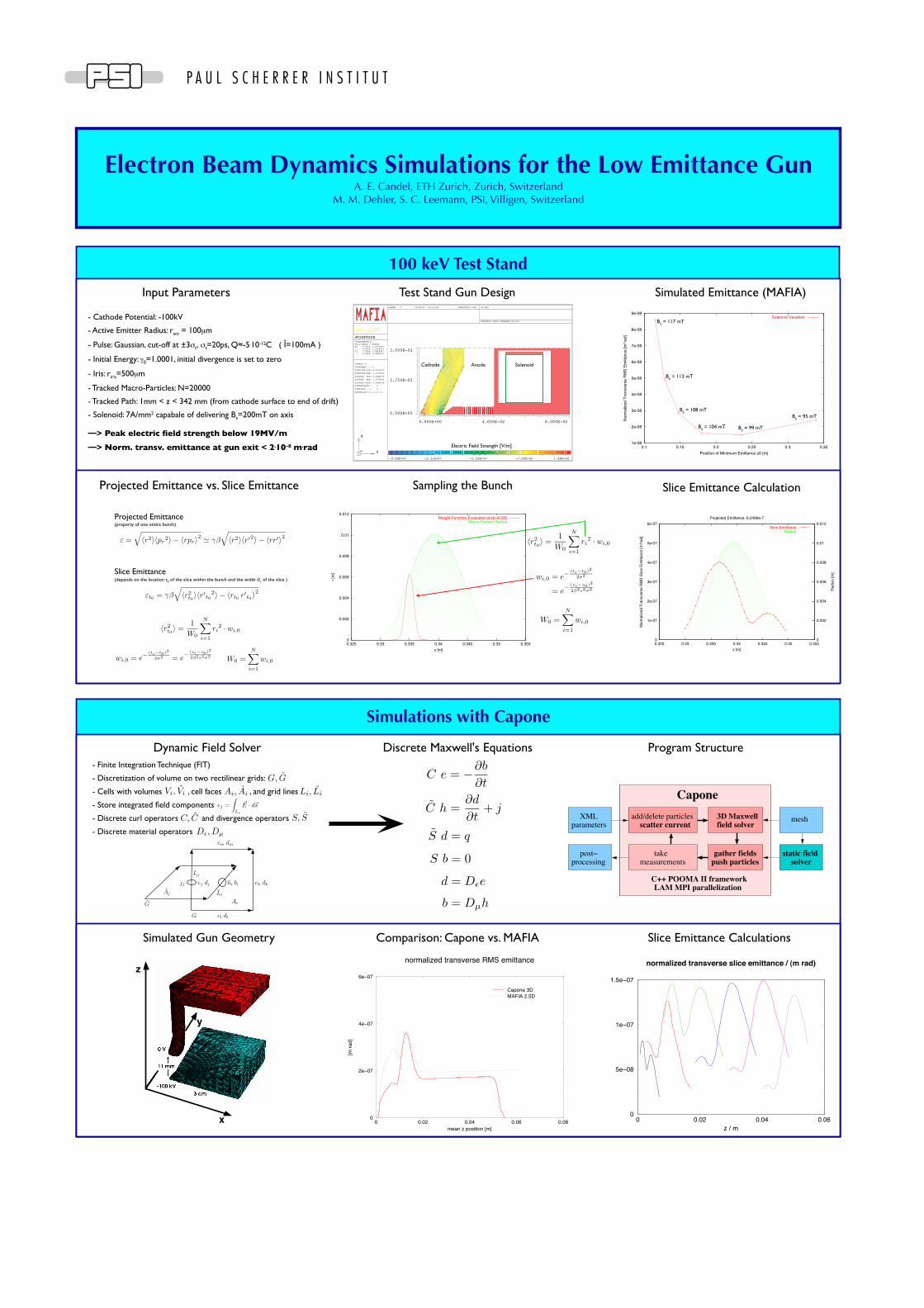
normalized transverse RMS emittance
Capone 3DMAFIA 2.5D
0 0.02 0.04 0.06z / m
0
5e!08
1e!07
1.5e!07
normalized transverse slice emittance / (m rad)
Test Stand Gun Design
= e− (zi−z0)2
2β2c2σ2
wi,0 = e−(ti−t0)2
2σ2
W0 =N∑
i=1
wi,0
〈r2t0〉 =
1W0
N∑i=1
ri2 · wi,0
- Cathode Potential: -100kV
- Active Emitter Radius: ract = 100µm
- Pulse: Gaussian, cut-off at ±3σt, σt=20ps, Q≈-5.10-12C ( Î=100mA )
- Initial Energy: γ0=1.0001, initial divergence is set to zero
- Iris: riris=500µm
- Tracked Macro-Particles: N=20000
- Tracked Path: 1mm < z < 342 mm (from cathode surface to end of drift)
- Solenoid: 7A/mm2 capabale of delivering Bz=200mT on axis
Input Parameters Simulated Emittance (MAFIA)
Projected Emittance vs. Slice Emittance Sampling the Bunch Slice Emittance Calculation
ε =√〈r2〉〈pr
2〉 − 〈rpr〉2 $ γβ√〈r2〉〈r′2〉 − 〈rr′〉2
εt0 = γβ√〈r2
t0〉〈r′t0
2〉 − 〈rt0 r′t0〉2
〈r2t0〉 =
1W0
N∑i=1
ri2 · wi,0
wi,0 = e−(ti−t0)2
2σ2 = e− (zi−z0)2
2β2c2σ2 W0 =N∑
i=1
wi,0
—> Peak electric field strength below 19MV/m
—> Norm. transv. emittance at gun exit < 2.10-8 m.rad
Cathode Anode Solenoid
Electric Field Strength [V/m]1e-08
2e-08
3e-08
4e-08
5e-08
6e-08
7e-08
8e-08
9e-08
0.1 0.15 0.2 0.25 0.3 0.35
Norm
alize
d Tr
ansv
erse
RM
S Em
ittan
ce [m
*rad]
Position of Minimum Emittance z0 [m]
Solenoid VariationBz = 117 mT
Bz = 113 mT
Bz = 108 mT
Bz = 104 mT Bz = 99 mT
Bz = 95 mT
0
0.002
0.004
0.006
0.008
0.01
0.012
0.325 0.33 0.335 0.34 0.345 0.35 0.355
r [m
]
z [m]
Weight Function Evaluated at z0=0.335Macro-Particle Radius
Dynamic Field Solver Discrete Maxwell's Equations Program Structure
Simulated Gun Geometry Comparison: Capone vs. MAFIA Slice Emittance Calculations
z
y
C e = −∂b
∂t
C h =∂d
∂t+ j
S d = q
S b = 0
d = Dεe
b = Dµh
- Finite Integration Technique (FIT)
- Discretization of volume on two rectilinear grids:
- Cells with volumes , cell faces , and grid lines
- Store integrated field components
- Discrete curl operators and divergence operators
- Discrete material operators
G, G
Vi, Vi Ai, Ai Li, Li
ej =∫
Lj
!E · d!s
C, C S, S
Dε,Dµ
x
y