ELECTROLYTIC MAN YUE ELECTRONICS CAPACITOR SAMXON …
15
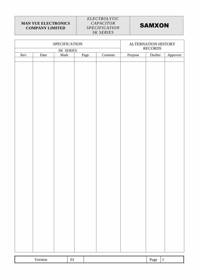
MAN YUE ELECTRONICS COMPANY LIMITED ELECTROLYTIC CAPACITOR SPECIFICATION SK SERIES Version 01 Page 1 SAMXON SPECIFICATION ALTERNATION HISTORY RECORDS SK SERIES Rev. Date Mark Page Contents Purpose Drafter Approver
Transcript of ELECTROLYTIC MAN YUE ELECTRONICS CAPACITOR SAMXON …
MAN YUE ELECTRONICS
COMPANY LIMITED
ELECTROLYTIC
CAPACITOR
SPECIFICATION
SK SERIES
Version 01 Page 1
SAMXON
SPECIFICATION ALTERNATION HISTORY RECORDS
SK SERIES Rev. Date Mark Page Contents Purpose Drafter Approver
MAN YUE ELECTRONICS
COMPANY LIMITED
ELECTROLYTIC
CAPACITOR
SPECIFICATION
SK SERIES
Version 01 Page 2
SAMXON
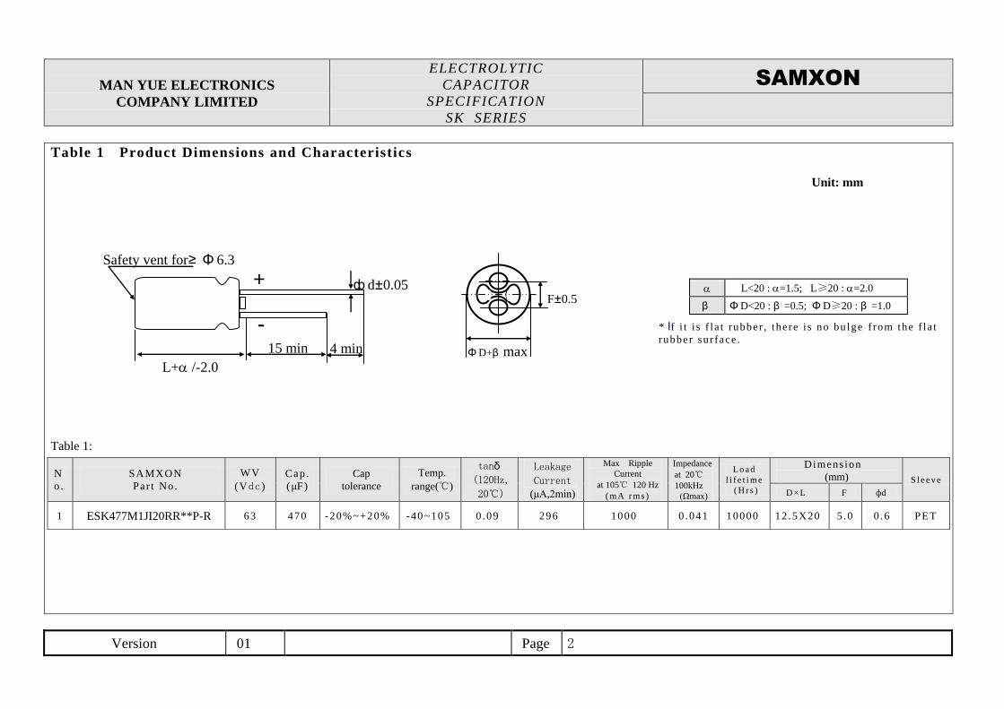
Table 1 Product Dimensions and Characteristics
Unit: mm
* If i t i s f l a t rubber , the re i s no bu lge f rom the f l a t
rubber sur face .
Table 1:
L<20 : =1.5; L≥20 : =2.0
β ΦD<20 : β =0.5; ΦD≥20 : β =1.0
N
o.
SAMXON
Par t No.
WV
(Vdc )
Cap .
(μF)
Cap
tolerance
Temp.
range(℃)
tanδ
(120Hz,
20℃)
Leakage
Current (μA,2min)
Max Ripple
Current
at 105℃ 120 Hz
( mA r ms )
Impedance
at 20℃
100kHz
(Ωmax)
L o a d
l i f e t i me
( H r s )
Dimens ion
(mm) S l e e v e
D ×L F фd
1 ESK477M1JI20RR**P-R 63 470 -20%~+20% -40~105 0 .09 296 1000 0 .041 10000 12 .5X20 5 .0 0 .6 PET
+ ф d±0.05
4 min 15 min
L+ /-2.0
Safety vent for≥ Φ 6.3
ΦD+β max
F±0.5
-
MAN YUE ELECTRONICS
COMPANY LIMITED
ELECTROLYTIC
CAPACITOR
SPECIFICATION
SK SERIES
Version 01 Page 3
SAMXON
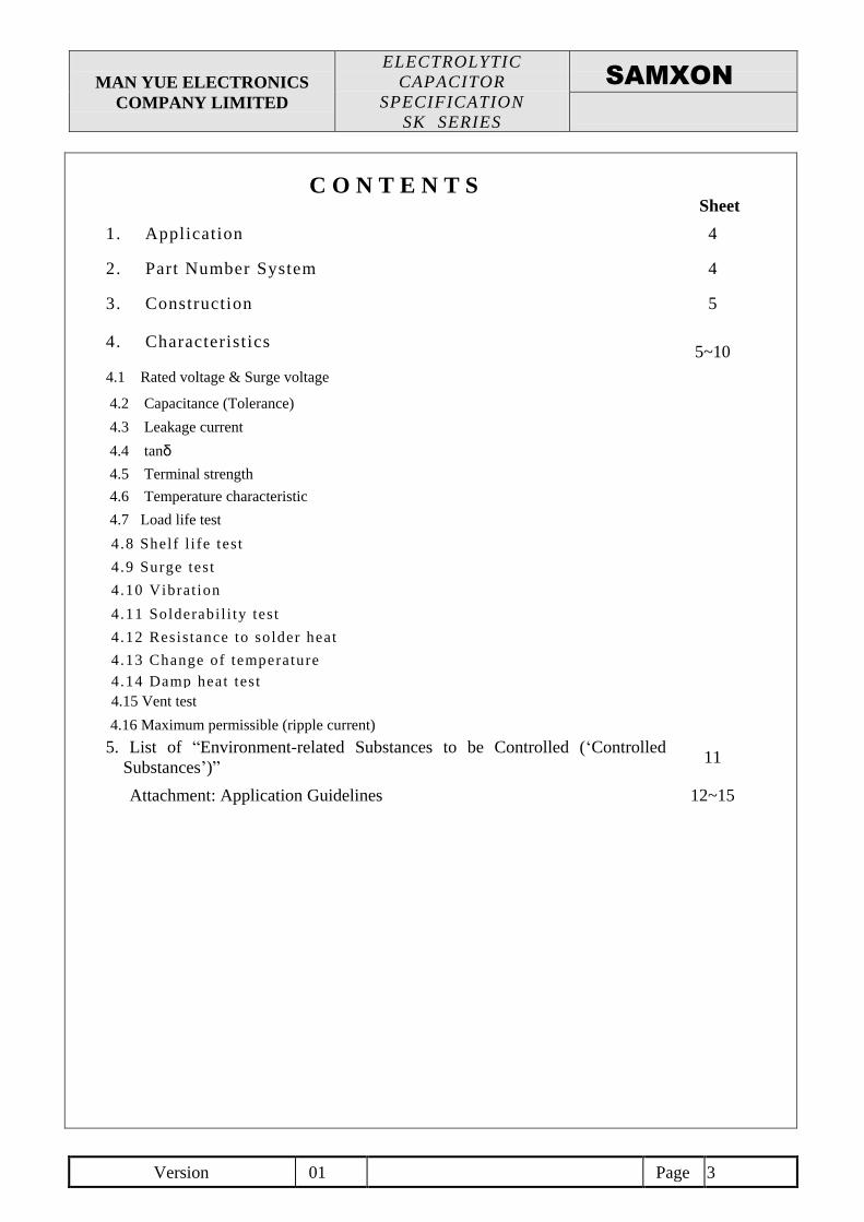
C O N T E N T S
Sheet
1. Application 4
2. Part Number System 4
3. Construction 5
4. Characteristics
5~10
4.1 Rated voltage & Surge voltage
4.2 Capacitance (Tolerance)
4.3 Leakage current
4.4 tanδ
4.5 Terminal strength
4.6 Temperature characteristic
4.7 Load life test
4 .8 Shelf l i fe test
4 .9 Surge test
4 .10 Vibrat ion
4 .11 Solderabi l i ty test
4 .12 Resistance to solder heat
4 .13 Change of temperature
4 .14 Damp heat test
4.15 Vent test
4.16 Maximum permissible (ripple current)
5. List of “Environment-related Substances to be Controlled (‘Controlled
Substances’)” 11
Attachment: Application Guidelines 12~15
MAN YUE ELECTRONICS
COMPANY LIMITED
ELECTROLYTIC
CAPACITOR
SPECIFICATION
SK SERIES
Version 01 Page 4
SAMXON
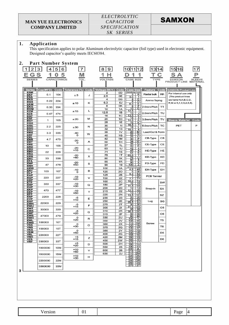
1. Application This specification applies to polar Aluminum electrolytic capacitor (foil type) used in electronic equipment.
Designed capacitor’s quality meets IEC60384.
2. Part Number System
MAN YUE ELECTRONICS
COMPANY LIMITED
ELECTROLYTIC
CAPACITOR
SPECIFICATION
SK SERIES
Version 01 Page 5
SAMXON
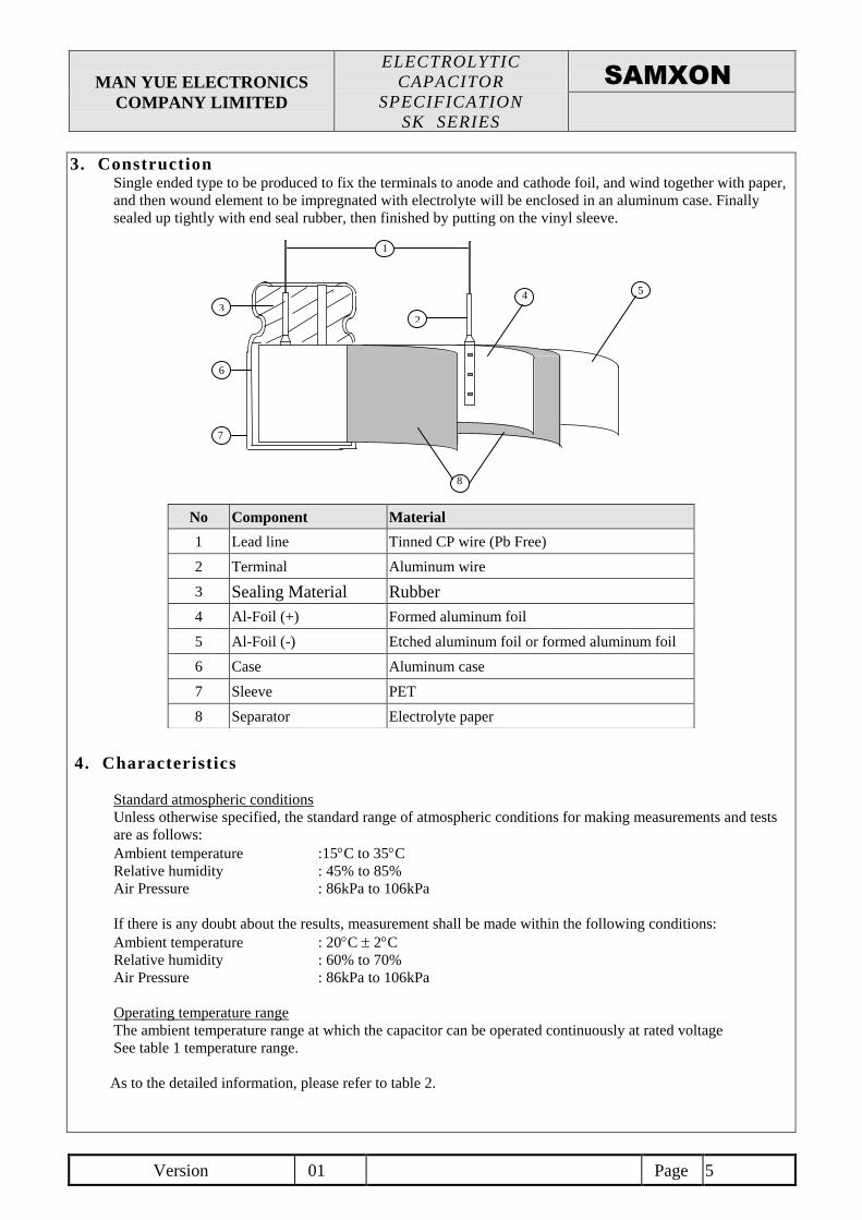
3. Construction Single ended type to be produced to fix the terminals to anode and cathode foil, and wind together with paper,
and then wound element to be impregnated with electrolyte will be enclosed in an aluminum case. Finally
sealed up tightly with end seal rubber, then finished by putting on the vinyl sleeve.
4. Characteristics
Standard atmospheric conditions
Unless otherwise specified, the standard range of atmospheric conditions for making measurements and tests
are as follows:
Ambient temperature :15C to 35C
Relative humidity : 45% to 85%
Air Pressure : 86kPa to 106kPa
If there is any doubt about the results, measurement shall be made within the following conditions:
Ambient temperature : 20C 2C
Relative humidity : 60% to 70%
Air Pressure : 86kPa to 106kPa
Operating temperature range
The ambient temperature range at which the capacitor can be operated continuously at rated voltage
See table 1 temperature range.
As to the detailed information, please refer to table 2.
No Component Material
1 Lead line Tinned CP wire (Pb Free)
2 Terminal Aluminum wire
3 Sealing Material Rubber
4 Al-Foil (+) Formed aluminum foil
5 Al-Foil (-) Etched aluminum foil or formed aluminum foil
6 Case Aluminum case
7 Sleeve PET
8 Separator Electrolyte paper
1
3
5
6
7
2
8
4
MAN YUE ELECTRONICS
COMPANY LIMITED
ELECTROLYTIC
CAPACITOR
SPECIFICATION
SK SERIES
Version 01 Page 6
SAMXON
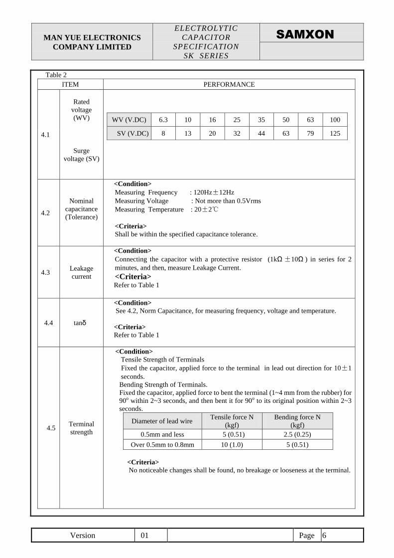
Table 2
ITEM PERFORMANCE
4.1
Rated
voltage
(WV)
WV (V.DC) 6.3 10 16 25 35 50 63 100
SV (V.DC) 8 13 20 32 44 63 79 125
Surge
voltage (SV)
4.2
Nominal
capacitance
(Tolerance)
<Condition>
Measuring Frequency : 120Hz±12Hz
Measuring Voltage : Not more than 0.5Vrms
Measuring Temperature : 20±2℃
<Criteria>
Shall be within the specified capacitance tolerance.
4.3 Leakage
current
<Condition>
Connecting the capacitor with a protective resistor (1kΩ±10Ω ) in series for 2
minutes, and then, measure Leakage Current.
<Criteria> Refer to Table 1
4.4 tanδ
<Condition>
See 4.2, Norm Capacitance, for measuring frequency, voltage and temperature.
<Criteria>
Refer to Table 1
4.5 Terminal
strength
<Condition>
Tensile Strength of Terminals
Fixed the capacitor, applied force to the terminal in lead out direction for 10±1
seconds.
Bending Strength of Terminals.
Fixed the capacitor, applied force to bent the terminal (1~4 mm from the rubber) for
90o within 2~3 seconds, and then bent it for 90o to its original position within 2~3
seconds.
Diameter of lead wire Tensile force N
(kgf)
Bending force N
(kgf)
0.5mm and less 5 (0.51) 2.5 (0.25)
Over 0.5mm to 0.8mm 10 (1.0) 5 (0.51)
<Criteria>
No noticeable changes shall be found, no breakage or looseness at the terminal.
MAN YUE ELECTRONICS
COMPANY LIMITED
ELECTROLYTIC
CAPACITOR
SPECIFICATION
SK SERIES
Version 01 Page 7
SAMXON
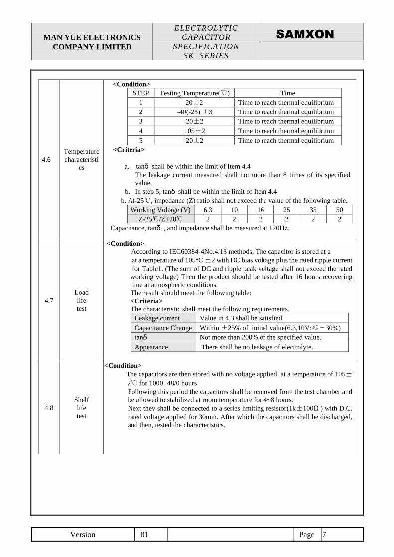
4.6
Temperature
characteristi
cs
<Condition>
STEP Testing Temperature(℃) Time
1 20±2 Time to reach thermal equilibrium
2 -40(-25) ±3 Time to reach thermal equilibrium
3 20±2 Time to reach thermal equilibrium
4 105±2 Time to reach thermal equilibrium
5 20±2 Time to reach thermal equilibrium
<Criteria>
a. tanδ shall be within the limit of Item 4.4
The leakage current measured shall not more than 8 times of its specified
value.
b. In step 5, tanδ shall be within the limit of Item 4.4
b. At-25℃, impedance (Z) ratio shall not exceed the value of the following table.
Working Voltage (V) 6.3 10 16 25 35 50
Z-25℃/Z+20℃ 2 2 2 2 2 2
Capacitance, tanδ , and impedance shall be measured at 120Hz.
4.7
Load
life
test
<Condition>
According to IEC60384-4No.4.13 methods, The capacitor is stored at a
at a temperature of 105°C ±2 with DC bias voltage plus the rated ripple current
for Table1. (The sum of DC and ripple peak voltage shall not exceed the rated
working voltage) Then the product should be tested after 16 hours recovering
time at atmospheric conditions.
The result should meet the following table:
<Criteria>
The characteristic shall meet the following requirements.
Leakage current Value in 4.3 shall be satisfied
Capacitance Change Within ±25% of initial value(6.3,10V:≤±30%)
tanδ Not more than 200% of the specified value.
Appearance There shall be no leakage of electrolyte.
4.8
Shelf
life
test
<Condition>
The capacitors are then stored with no voltage applied at a temperature of 105±
2℃ for 1000+48/0 hours.
Following this period the capacitors shall be removed from the test chamber and
be allowed to stabilized at room temperature for 4~8 hours.
Next they shall be connected to a series limiting resistor(1k±100Ω ) with D.C.
rated voltage applied for 30min. After which the capacitors shall be discharged,
and then, tested the characteristics.
MAN YUE ELECTRONICS
COMPANY LIMITED
ELECTROLYTIC
CAPACITOR
SPECIFICATION
SK SERIES
Version 01 Page 8
SAMXON
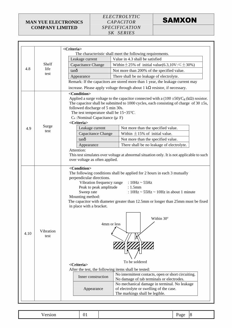
4.8
Shelf
life
test
<Criteria>
The characteristic shall meet the following requirements.
Leakage current Value in 4.3 shall be satisfied
Capacitance Change Within±25% of initial value(6.3,10V:≤±30%)
tanδ Not more than 200% of the specified value.
Appearance There shall be no leakage of electrolyte.
Remark: If the capacitors are stored more than 1 year, the leakage current may
increase. Please apply voltage through about 1 kΩ resistor, if necessary.
4.9 Surge
test
<Condition>
Applied a surge voltage to the capacitor connected with a (100 ±50)/CR (kΩ) resistor.
The capacitor shall be submitted to 1000 cycles, each consisting of charge of 30 ±5s,
followed discharge of 5 min 30s.
The test temperature shall be 15~35℃.
CR :Nominal Capacitance (μ F)
<Criteria>
Leakage current Not more than the specified value.
Capacitance Change Within ±15% of initial value.
tanδ Not more than the specified value.
Appearance There shall be no leakage of electrolyte.
Attention:
This test simulates over voltage at abnormal situation only. It is not applicable to such
over voltage as often applied.
4.10 Vibration
test
<Condition>
The following conditions shall be applied for 2 hours in each 3 mutually
perpendicular directions.
Vibration frequency range : 10Hz ~ 55Hz
Peak to peak amplitude : 1.5mm
Sweep rate : 10Hz ~ 55Hz ~ 10Hz in about 1 minute
Mounting method:
The capacitor with diameter greater than 12.5mm or longer than 25mm must be fixed
in place with a bracket.
<Criteria>
After the test, the following items shall be tested:
Inner construction No intermittent contacts, open or short circuiting.
No damage of tab terminals or electrodes.
Appearance
No mechanical damage in terminal. No leakage
of electrolyte or swelling of the case.
The markings shall be legible.
4mm or less
Within 30
To be soldered
MAN YUE ELECTRONICS
COMPANY LIMITED
ELECTROLYTIC
CAPACITOR
SPECIFICATION
SK SERIES
Version 01 Page 9
SAMXON
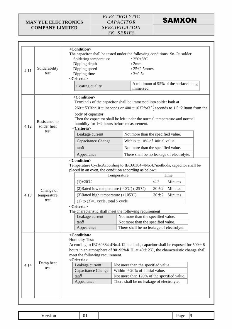
4.11 Solderability
test
<Condition>
The capacitor shall be tested under the following conditions: Sn-Cu solder
Soldering temperature : 2503C
Dipping depth : 2mm
Dipping speed : 252.5mm/s
Dipping time : 30.5s
<Criteria>
Coating quality A minimum of 95% of the surface being
immersed
4.12
Resistance to
solder heat
test
<Condition>
Terminals of the capacitor shall be immersed into solder bath at
260±5℃for10±1seconds or 400±10℃for3
0
1seconds to 1.5~2.0mm from the
body of capacitor .
Then the capacitor shall be left under the normal temperature and normal
humidity for 1~2 hours before measurement.
<Criteria>
Leakage current Not more than the specified value.
Capacitance Change Within ±10% of initial value.
tanδ Not more than the specified value.
Appearance There shall be no leakage of electrolyte.
4.13
Change of
temperature
test
<Condition>
Temperature Cycle:According to IEC60384-4No.4.7methods, capacitor shall be
placed in an oven, the condition according as below:
Temperature Time
(1)+20℃ ≤ 3 Minutes
(2)Rated low temperature (-40℃) (-25℃) 30±2 Minutes
(3)Rated high temperature (+105℃) 30±2 Minutes
(1) to (3)=1 cycle, total 5 cycle
<Criteria>
The characteristic shall meet the following requirement
Leakage current Not more than the specified value.
tanδ Not more than the specified value.
Appearance There shall be no leakage of electrolyte.
4.14 Damp heat
test
<Condition>
Humidity Test:
According to IEC60384-4No.4.12 methods, capacitor shall be exposed for 500±8
hours in an atmosphere of 90~95%R H .at 40±2℃, the characteristic change shall
meet the following requirement.
<Criteria>
Leakage current Not more than the specified value.
Capacitance Change Within ±20% of initial value.
tanδ Not more than 120% of the specified value.
Appearance There shall be no leakage of electrolyte.
MAN YUE ELECTRONICS
COMPANY LIMITED
ELECTROLYTIC
CAPACITOR
SPECIFICATION
SK SERIES
Version 01 Page 10
SAMXON
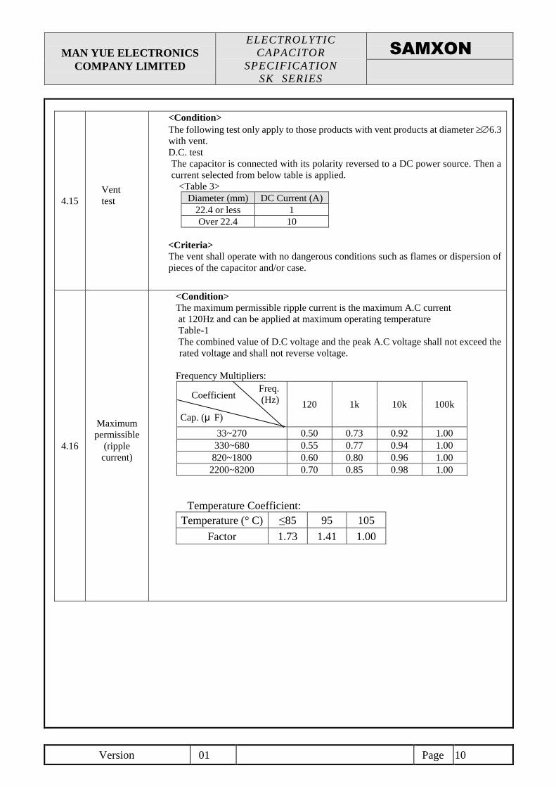
4.15
Vent
test
<Condition>
The following test only apply to those products with vent products at diameter 6.3
with vent.
D.C. test
The capacitor is connected with its polarity reversed to a DC power source. Then a
current selected from below table is applied.
<Table 3>
Diameter (mm) DC Current (A)
22.4 or less 1
Over 22.4 10
<Criteria>
The vent shall operate with no dangerous conditions such as flames or dispersion of
pieces of the capacitor and/or case.
4.16
Maximum
permissible
(ripple
current)
<Condition>
The maximum permissible ripple current is the maximum A.C current
at 120Hz and can be applied at maximum operating temperature
Table-1
The combined value of D.C voltage and the peak A.C voltage shall not exceed the
rated voltage and shall not reverse voltage.
Frequency Multipliers:
120 1k 10k 100k
33~270 0.50 0.73 0.92 1.00
330~680 0.55 0.77 0.94 1.00
820~1800 0.60 0.80 0.96 1.00
2200~8200 0.70 0.85 0.98 1.00
Temperature Coefficient:
Temperature (° C) ≤85 95 105
Factor 1.73 1.41 1.00
Freq.
(Hz)
Cap. (μ F)
Coefficient
MAN YUE ELECTRONICS
COMPANY LIMITED
ELECTROLYTIC
CAPACITOR
SPECIFICATION
SK SERIES
Version 01 Page 11
SAMXON
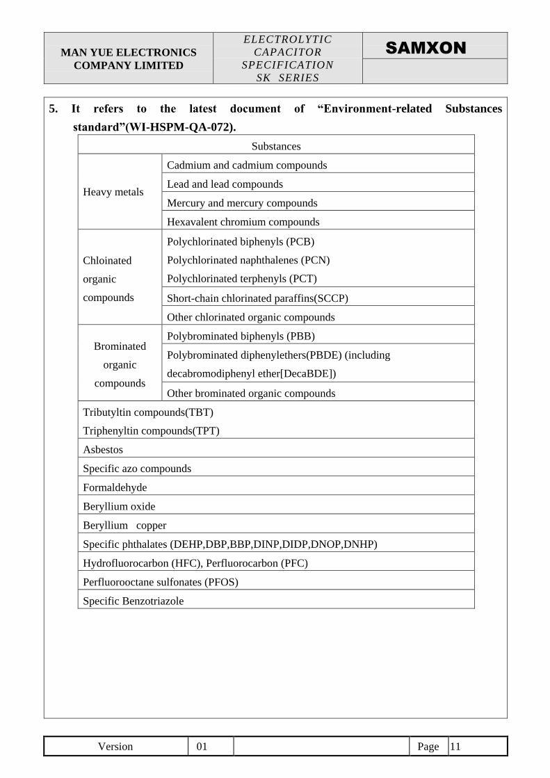
5. It refers to the latest document of “Environment-related Substances
standard”(WI-HSPM-QA-072).
Substances
Heavy metals
Cadmium and cadmium compounds
Lead and lead compounds
Mercury and mercury compounds
Hexavalent chromium compounds
Chloinated
organic
compounds
Polychlorinated biphenyls (PCB)
Polychlorinated naphthalenes (PCN)
Polychlorinated terphenyls (PCT)
Short-chain chlorinated paraffins(SCCP)
Other chlorinated organic compounds
Brominated
organic
compounds
Polybrominated biphenyls (PBB)
Polybrominated diphenylethers(PBDE) (including
decabromodiphenyl ether[DecaBDE])
Other brominated organic compounds
Tributyltin compounds(TBT)
Triphenyltin compounds(TPT)
Asbestos
Specific azo compounds
Formaldehyde
Beryllium oxide
Beryllium copper
Specific phthalates (DEHP,DBP,BBP,DINP,DIDP,DNOP,DNHP)
Hydrofluorocarbon (HFC), Perfluorocarbon (PFC)
Perfluorooctane sulfonates (PFOS)
Specific Benzotriazole
MAN YUE ELECTRONICS
COMPANY LIMITED
ELECTROLYTIC
CAPACITOR
SPECIFICATION
SK SERIES
Version 01 Page 12
SAMXON
Attachment: Application Guidelines
1.Circuit Design
1.1 Operating Temperature and Frequency
Electrolytic capacitor electrical parameters are normally specified at 20℃ temperature and 120Hz frequency. These parameters
vary with changes in temperature and frequency. Circuit designers should take these changes into consideration.
(1) Effects of operating temperature on electrical parameters
a) At higher temperatures, leakage current and capacitance increase while equivalent series resistance (ESR) decreases.
b) At lower temperatures, leakage current and capacitance decrease while equivalent series resistance (ESR) increases.
(2) Effects of frequency on electrical parameters
a) At higher frequencies capacitance and impedance decrease while tanδ increases.
b) At lower frequencies, ripple current generated heat will rise due to an increase in equivalent series resistance (ESR).
1.2 Operating Temperature and Life Expectancy
See the file: Life calculation of aluminum electrolytic capacitor
1.3 Common Application Conditions to Avoid
The following misapplication load conditions will cause rapid deterioration to capacitor electrical parameters. In addition, rapid
heating and gas generation within the capacitor can occur causing the pressure relief vent to operate and resultant leakage of
electrolyte. Under Leaking electrolyte is combustible and electrically conductive.
(1) Reverse Voltage
DC capacitors have polarity. Verify correct polarity before insertion. For circuits with changing or uncertain polarity, use DC bipolar
capacitors. DC bipolar capacitors are not suitable for use in AC circuits.
(2) Charge / Discharge Applications
Standard capacitors are not suitable for use in repeating charge / discharge applications. For charge / discharge applications consult
us and advise actual conditions.
(3) Over voltage
Do not apply voltages exceeding the maximum specified rated voltage. Voltages up to the surge voltage rating are acceptable for
short periods of time. Ensure that the sum of the DC voltage and the superimposed AC ripple voltage does not exceed the rated
voltage.
(4) Ripple Current
Do not apply ripple currents exceeding the maximum specified value. For high ripple current applications, use a capacitor designed
for high ripple currents or contact us with your requirements. Ensure that allowable ripple currents superimposed on low DC bias
voltages do not cause reverse voltage conditions.
1.4 Using Two or More Capacitors in Series or Parallel
(1) Capacitors Connected in Parallel
The circuit resistance can closely approximate the series resistance of the capacitor causing an imbalance of ripple current loads
within the capacitors. Careful design of wiring methods can minimize the possibility of excessive ripple currents applied to a
capacitor.
(2) Capacitors Connected in Series
Normal DC leakage current differences among capacitors can cause voltage imbalances. The use of voltage divider shunt resistors
with consideration to leakage current can prevent capacitor voltage imbalances.
1.5 Capacitor Mounting Considerations
(1) Double Sided Circuit Boards
Avoid wiring pattern runs, which pass between the mounted capacitor and the circuit board.
When dipping into a solder bath, excess solder may collect under the capacitor by capillary action and short circuit the anode and
cathode terminals.
(2)Circuit Board Hole Positioning
The vinyl sleeve of the capacitor can be damaged if solder passes through a lead hole for subsequently processed parts. Special care
when locating hole positions in proximity to capacitors is recommended.
(3)Circuit Board Hole Spacing
The circuit board holes spacing should match the capacitor lead wire spacing within the specified tolerances. Incorrect spacing can
cause excessive lead wire stress during the insertion process. This may result in premature capacitor failure due to short or open
circuit, increased leakage current, or electrolyte leakage.
(4) Clearance for Case Mounted Pressure Relief vents
Capacitors with case mounted pressure relief vents require sufficient clearance to allow for proper vent operation. The minimum
clearances are dependent on capacitor diameters as proper vent operation. The minimum clearances are dependent on capacitor
diameters as follows.
φ6.3~φ16mm:2mm minimum, φ18~φ35mm:3mm minimum, φ40mm or greater:5mm minimum.
(5) Clearance for Seal Mounted Pressure Relief Vents
A hole in the circuit board directly under the seal vent location is required to allow proper release of pressure.
MAN YUE ELECTRONICS
COMPANY LIMITED
ELECTROLYTIC
CAPACITOR
SPECIFICATION
SK SERIES
Version 01 Page 13
SAMXON
(6) Wiring Near the Pressure Relief Vent
Avoid locating high voltage or high current wiring or circuit board paths above the pressure relief vent. Flammable, high temperature gas
exceeding 100℃ may be released which could dissolve the wire insulation and ignite.
(7) Circuit Board patterns Under the Capacitor
Avoid circuit board runs under the capacitor as electrolyte leakage could cause an electrical short.
(8) Screw Terminal Capacitor Mounting
Do not orient the capacitor with the screw terminal side of the capacitor facing downwards.
Tighten the terminal and mounting bracket screws within the torque range specified in the specification.
1.6 Electrical Isolation of the Capacitor
Completely isolate the capacitor as follows.
(1) Between the cathode and the case (except for axially leaded B types) and between the anode terminal and other circuit paths
(2) Between the extra mounting terminals (on T types) and the anode terminal, cathode terminal, and other circuit paths.
1.7 The Product endurance should take the sample as the standard.
1.8 If conduct the load or shelf life test, must be collect date code within 6 months products of sampling.
1.9 Capacitor Sleeve
The vinyl sleeve or laminate coating is intended for marking and identification purposes and is not meant to electrically insulate the
capacitor.
The sleeve may split or crack if immersed into solvents such as toluene or xylene, and then exposed to high temperatures.
CAUTION!
Always consider safety when designing equipment and circuits. Plan for worst case failure modes such as short circuits and open
circuits which could occur during use.
(1) Provide protection circuits and protection devices to allow safe failure modes.
(2) Design redundant or secondary circuits where possible to assure continued operation in case of main circuit failure.
2.Capacitor Handling Techniques
2.1 Considerations Before Using
(1) Capacitors have a finite life. Do not reuse or recycle capacitors from used equipment.
(2) Transient recovery voltage may be generated in the capacitor due to dielectric absorption. If required, this voltage can be discharged
with a resistor with a value of about 1kΩ.
(3) Capacitors stored for long periods of time may exhibit an increase in leakage current. This can be corrected by gradually applying
rated voltage in series with a resistor of approximately 1kΩ.
(4) If capacitors are dropped, they can be damaged mechanically or electrically. Avoid using dropped capacitors.
(5) Dented or crushed capacitors should not be used. The seal integrity can be compromised and loss of electrolyte / shortened life can
result.
2.2 Capacitor Insertion
(1) Verify the correct capacitance and rated voltage of the capacitor.
(2) Verify the correct polarity of the capacitor before inserting.
(3) Verify the correct hole spacing before insertion (land pattern size on chip type) to avoid stress on the terminals.
(4) Ensure that the auto insertion equipment lead clinching operation does not stress the capacitor leads where they enter the seal of the
capacitor.
For chip type capacitors, excessive mounting pressure can cause high leakage current, short circuit, or disconnection.
2.3 Manual Soldering
(1) Observe temperature and time soldering specifications or do not exceed temperatures of 400 ℃ for 3 seconds or less.
(2) If lead wires must be formed to meet terminal board hole spacing, avoid stress on the lead wire where it enters the capacitor seal.
(3) If a soldered capacitor must be removed and reinserted, avoid excessive stress to the capacitor leads.
(4) Avoid touching the tip of the soldering iron to the capacitor, to prevent melting of the vinyl sleeve.
2.4 Flow Soldering
(1) Do not immerse the capacitor body into the solder bath as excessive internal pressure could result.
(2) Observe proper soldering conditions (temperature, time, etc.) Do not exceed the specified limits.
(3) Do not allow other parts or components to touch the capacitor during soldering.
2.5 Other Soldering Considerations
Rapid temperature rises during the preheat operation and resin bonding operation can cause cracking of the capacitor vinyl sleeve.
For heat curing, do not exceed 150℃ for a maximum time of 2 minutes.
MAN YUE ELECTRONICS
COMPANY LIMITED
ELECTROLYTIC
CAPACITOR
SPECIFICATION
SK SERIES
Version 01 Page 14
SAMXON
2.6 Capacitor Handling after Solder
(1). Avoid movement of the capacitor after soldering to prevent excessive stress on the lead wires where they enter the seal.
(2). Do not use capacitor as a handle when moving the circuit board assembly.
(3). Avoid striking the capacitor after assembly to prevent failure due to excessive shock.
2.7 Circuit Board Cleaning
(1 ) Circuit boards can be immersed or ultrasonically cleaned using suitable cleaning solvents for up 5 minutes and up to 60℃ maximum
temperatures. The boards should be thoroughly rinsed and dried. The use of ozone depleting cleaning agents is not recommended in
the interest of protecting the environment.
(2) Avoid using the following solvent groups unless specifically allowed for in the specification;
Halogenated cleaning solvents: except for solvent resistant capacitor types, halogenated solvents can permeate the seal and cause
internal capacitor corrosion and failure. For solvent resistant capacitors, carefully follow the temperature and time requirements of
the specification. 1-1-1 trichloroethane should never be used on any aluminum electrolytic capacitor.
Alkali solvents : could attack and dissolve the aluminum case.
Petroleum based solvents: deterioration of the rubber seal could result.
Xylene : deterioration of the rubber seal could result.
Acetone : removal of the ink markings on the vinyl sleeve could result.
(3 ) A thorough drying after cleaning is required to remove residual cleaning solvents which may be trapped between the capacitor and the
circuit board. Avoid drying temperatures, which exceed the maximum rated temperature of the capacitor.
(4) Monitor the contamination levels of the cleaning solvents during use by electrical conductivity, pH, specific gravity, or water content.
Chlorine levels can rise with contamination and adversely affect the performance of the capacitor. Please consult us for additional
information about acceptable cleaning solvents or cleaning methods.
2.8 Mounting Adhesives and Coating Agents
When using mounting adhesives or coating agents to control humidity, avoid using materials containing halogenated solvents. Also,
avoid the use of chloroprene based polymers. After applying adhesives or coatings, dry thoroughly to prevent residual solvents from
being trapped between the capacitor and the circuit board.
3. Precautions for using capacitors
3.1 Environmental Conditions
Capacitors should not be stored or used in the following environments.
(1) Temperature exposure above the maximum rated or below the minimum rated temperature of the capacitor.
(2) Direct contact with water, salt water, or oil.
(3) High humidity conditions where water could condense on the capacitor.
(4) Exposure to toxic gases such as hydrogen sulfide, sulfuric acid, nitric acid chlorine, or ammonia.
(5) Exposure to ozone, radiation, or ultraviolet rays.
(6) Vibration and shock conditions exceeding specified requirements.
3.2 Electrical Precautions
(1) Avoid touching the terminals of the capacitor as possible electric shock could result. The exposed aluminum case is not insulated and
could also cause electric shock if touched.
(2) Avoid short circuit the area between the capacitor terminals with conductive materials including liquids such as acids or alkaline
solutions.
4. Emergency Procedures
(1) If the pressure relief vent of the capacitor operates, immediately turn off the equipment and disconnect form the power source. This
will minimize additional damage caused by the vaporizing electrolyte.
(2) Avoid contact with the escaping electrolyte gas which can exceed 100℃ temperatures.
If electrolyte or gas enters the eye, immediately flush the eyes with large amounts of water.
If electrolyte or gas is ingested by month, gargle with water.
If electrolyte contacts the skin, wash with soap and water.
5. Long Term Storage
Leakage current of a capacitor increases with long storage times. The aluminum oxide film deteriorates as a function of temperature and
time. If used without reconditioning, an abnormally high current will be required to restore the oxide film. This current surge could cause
the circuit or the capacitor to fail. After one year, a capacitor should be reconditioned by applying rated voltage in series with a 1000Ω,
current limiting resistor for a time period of 30 minutes . If the expired date of products date code is over eighteen months, the products
should be return to confirmation.
5.1 Environmental Conditions
MAN YUE ELECTRONICS
COMPANY LIMITED
ELECTROLYTIC
CAPACITOR
SPECIFICATION
SK SERIES
Version 01 Page 15
SAMXON
The capacitor shall be not use in the following condition:
(1) Temperature exposure above the maximum rated or below the minimum rated temperature of the capacitor.
(2) Direct contact with water, salt water, or oil.
(3) High humidity conditions where water could condense on the capacitor.
(4) Exposure to toxic gases such as hydrogen sulfide, sulfuric acid, nitric acid, chlorine, or ammonia.
(5) Exposure to ozone, radiation, or ultraviolet rays.
(6) Vibration and shock conditions exceeding specified requirements.
6. Capacitor Disposal
When disposing of capacitors, use one of the following methods.
Incinerate after crushing the capacitor or puncturing the can wall (to prevent explosion due to internal pressure rise).
Capacitors should be incinerated at high temperatures to prevent the release of toxic gases such as chlorine from the
polyvinyl chloride sleeve, etc.
Dispose of as solid waste.
NOTE: Local laws may have specific disposal requirements, which must be followed.