Electrically Testing Long Cables - Cami Research...Feb 2017 42 Nagog Park, Suite 115, Acton, MA...
8
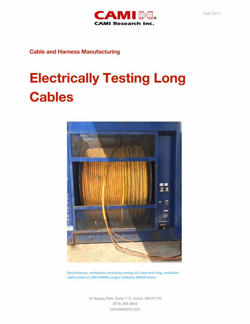
Feb 2017 42 Nagog Park, Suite 115, Acton, MA 01720 (978) 266 2655 camiresearch.com Cable and Harness Manufacturing Electrically Testing Long Cables Simultaneous, multipoint continuity testing of a twomile long, multicore cable (rated at 10Ω/1000ft) using a CableEye M3UH tester.
Transcript of Electrically Testing Long Cables - Cami Research...Feb 2017 42 Nagog Park, Suite 115, Acton, MA...
Feb 2017
42 Nagog Park, Suite 115, Acton, MA 01720
(978) 266 2655 camiresearch.com
Cable and Harness Manufacturing
Electrically Testing Long Cables
Simultaneous, multipoint continuity testing of a two-‐mile long, multicore cable (rated at 10Ω/1000ft) using a CableEye M3UH tester.
Cable and Harness Manufacturing: Electrically Testing Long Cables
camiresearch.com 2 © 2016 by CAMI Research Inc.
All Rights Reserved
Overview
Copper cables surround all aspects of modern technology, and despite increasing applications for fiber optics in communications, we will continue to employ copper conductors to deliver power, effect electrical control, and carry signal data inexpensively for the foreseeable future. As long as industry demands copper cables for such applications, these manufactured items will require testing to ensure proper function and conformance to quality standards. In some application, we also require mid-life in-situ testing
prior to the end of the product's useful life. Failure to test adequately may lead to significant economic losses or catastrophic results.
Mature and readily-available technology exists to test electronics cables and wire harness of less than 10 ft (3 m). Testing cables of tens, hundreds, or thousands of feet makes new demands on the test equipment, test procedures, and the operator to obtain accurate test data without damage to the equipment or safety risks to the operator. This article focuses on these issues.
How Do Long Cables Electrically Differ from Short Ones?
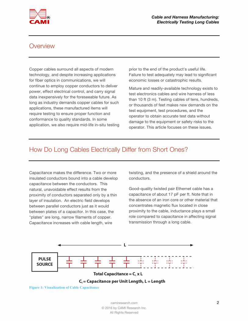
Capacitance makes the difference. Two or more insulated conductors bound into a cable develop capacitance between the conductors. This natural, unavoidable effect results from the proximity of conductors separated only by a thin layer of insulation. An electric field develops between parallel conductors just as it would between plates of a capacitor. In this case, the "plates" are long, narrow filaments of copper. Capacitance increases with cable length, wire
twisting, and the presence of a shield around the conductors.
Good-quality twisted pair Ethernet cable has a capacitance of about 17 pF per ft. Note that in the absence of an iron core or other material that concentrates magnetic flux located in close proximity to the cable, inductance plays a small role compared to capacitance in affecting signal transmission through a long cable.
Figure 1: Visualization of Cable Capacitance
Cable and Harness Manufacturing: Electrically Testing Long Cables
camiresearch.com 3 © 2016 by CAMI Research Inc.
All Rights Reserved
How does Increasing Capacitance Affect Wire Resistance Measurement?
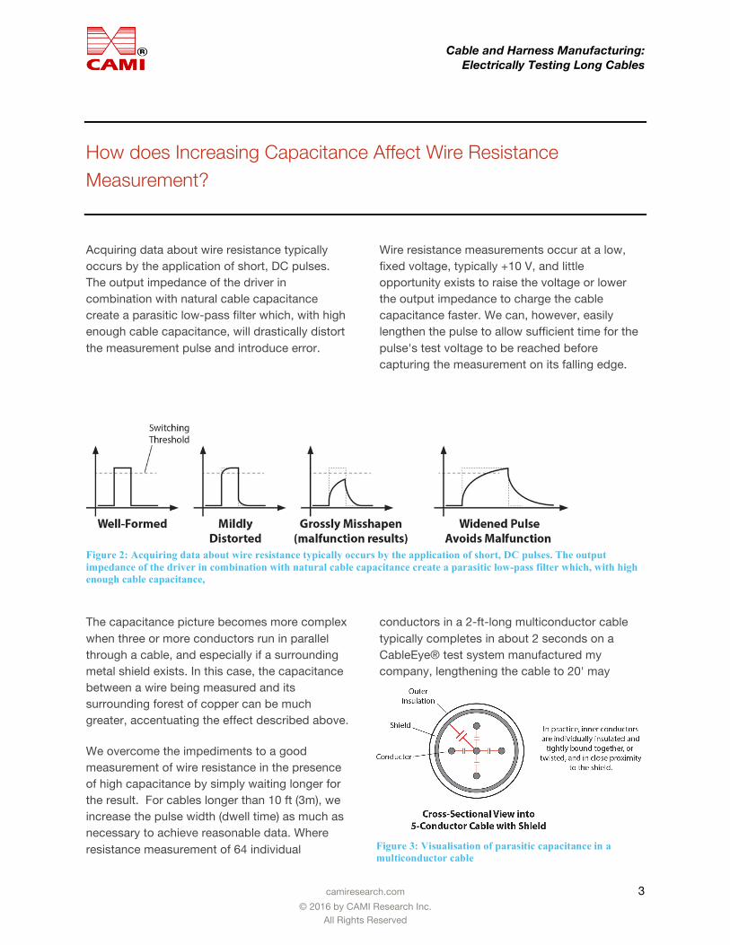
Acquiring data about wire resistance typically occurs by the application of short, DC pulses. The output impedance of the driver in combination with natural cable capacitance create a parasitic low-pass filter which, with high enough cable capacitance, will drastically distort the measurement pulse and introduce error.
Wire resistance measurements occur at a low, fixed voltage, typically +10 V, and little opportunity exists to raise the voltage or lower the output impedance to charge the cable capacitance faster. We can, however, easily lengthen the pulse to allow sufficient time for the pulse's test voltage to be reached before capturing the measurement on its falling edge.
Figure 2: Acquiring data about wire resistance typically occurs by the application of short, DC pulses. The output impedance of the driver in combination with natural cable capacitance create a parasitic low-pass filter which, with high enough cable capacitance,
The capacitance picture becomes more complex when three or more conductors run in parallel through a cable, and especially if a surrounding metal shield exists. In this case, the capacitance between a wire being measured and its surrounding forest of copper can be much greater, accentuating the effect described above.
We overcome the impediments to a good measurement of wire resistance in the presence of high capacitance by simply waiting longer for the result. For cables longer than 10 ft (3m), we increase the pulse width (dwell time) as much as necessary to achieve reasonable data. Where resistance measurement of 64 individual
conductors in a 2-ft-long multiconductor cable typically completes in about 2 seconds on a CableEye® test system manufactured my company, lengthening the cable to 20' may
Figure 3: Visualisation of parasitic capacitance in a multiconductor cable
Cable and Harness Manufacturing: Electrically Testing Long Cables
camiresearch.com 4 © 2016 by CAMI Research Inc.
All Rights Reserved
require 3 seconds, and lengthening it to 200' would have us wait about 11 seconds for the result.
How does Increasing Capacitance Affect Insulation Measurement?
Ten feet of 22-gauge stranded copper wire has an ideal resistance of about 0.16 Ω. For good signal transmission, the lower the resistance the better. Wire insulation, however, has the opposite requirement – the higher the resistance, the better.
Making measurements on modern insulation whose values are typically 100 MΩ or more at a thickness of only 25 mils (0.64mm) imposes very different requirements on test equipment than does measuring copper. While a low voltage of +10 V or less will push enough current through a copper wire to make highly accurate resistance measurements, hundreds or thousands of volts may be necessary to push enough electrons through good insulation to obtain a measurable current. We typically refer to test equipment designed to do this as a hipot ("high potential") tester.
We measure insulation resistance in Megohms (106 Ω) or Gigohms (109 Ω) and wish to find the leakage current through the insulation, in microamps, at a specified voltage to compute this number. An additional test aims to certify that the insulation does not suffer dielectric breakdown at a specified voltage, typically a voltage higher than that used to measure leakage current. Dielectric breakdown occurs when the insulation (the "dielectric") ionizes (typically at a pinhole point in the insulation) to form low resistance conductive path through the insulator. Insulation which experiences dielectric breakdown not only fails the test, but renders the cable damaged and unusable as the result of a
small, open tunnel where insulation had once isolated the environment from the copper conductor.
As with copper wire measurement, we start with a pulse of high voltage, and the thought that we need only to measure the leakage current at this voltage to have our answer. Quickly, however, problems develop.
First, for reasons of operator safety when using high voltage test equipment, we limit the maximum permissible output current to 1.5 mA. In fact, in practice, we prefer that the maximum limit, also called "trip current" be even less. Why? Consider that at a typical test voltage of 1,000 Vdc, should a pinhole opening in the insulation develop, the current will rapidly rise to the trip limit which, at 1.5 mA, would focus 1.5 W of power (1,000 V x 0.0015 A) into an extremely narrow pinhole channel with timing as fast as a lightening strike. The heat developed during the microseconds of a discharge could burn a hole in the insulation or vaporize copper on the wires' surfaces, permanently damaging the cable.
Keeping the trip current low, then, is desirable. This, however, imposes another restriction resulting from cable capacitance. The current that must flow into the cable, "i", as the test voltage "V" is applied, is a function of the cable's parasitic capacitance and the rate of change of the rising voltage, "dV/dt":
i = C dV/dt
Cable and Harness Manufacturing: Electrically Testing Long Cables
camiresearch.com 5 © 2016 by CAMI Research Inc.
All Rights Reserved
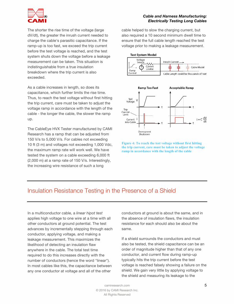
The shorter the rise time of the voltage (large dV/dt), the greater the inrush current needed to charge the cable's parasitic capacitance. If the ramp-up is too fast, we exceed the trip current before the test voltage is reached, and the test system shuts down the voltage before a leakage measurement can be taken. This situation is indistinguishable from a true insulation breakdown where the trip current is also exceeded.
As a cable increases in length, so does its capacitance, which further limits the rise time. Thus, to reach the test voltage without first hitting the trip current, care must be taken to adjust the voltage ramp in accordance with the length of the cable - the longer the cable, the slower the ramp up.
The CableEye HVX Tester manufactured by CAMI Research has a ramp that can be adjusted from 150 V/s to 5,000 V/s. For cables not exceeding 10 ft (3 m) and voltages not exceeding 1,000 Vdc, the maximum ramp rate will work well. We have tested the system on a cable exceeding 6,000 ft (2,000 m) at a ramp rate of 150 V/s. Interestingly, the increasing wire resistance of such a long
cable helped to slow the charging current, but also required a 10 second minimum dwell time to ensure that the full cable length reached the test voltage prior to making a leakage measurement.
Figure 4: To reach the test voltage without first hitting the trip current, care must be taken to adjust the voltage ramp in accordance with the length of the cable
Insulation Resistance Testing in the Presence of a Shield
In a multiconductor cable, a linear hipot test applies high voltage to one wire at a time with all other conductors at ground potential. The test advances by incrementally stepping through each conductor, applying voltage, and making a leakage measurement. This maximizes the likelihood of detecting an insulation flaw anywhere in the cable. The total test time required to do this increases directly with the number of conductors (hence the word "linear"). In most cables like this, the capacitance between any one conductor at voltage and all of the other
conductors at ground is about the same, and in the absence of insulation flaws, the insulation resistance for each should also be about the same.
If a shield surrounds the conductors and must also be tested, the shield capacitance can be an order of magnitude higher than that of any one conductor, and current flow during ramp-up typically hits the trip current before the test voltage is reached falsely showing a failure on the shield. We gain very little by applying voltage to the shield and measuring its leakage to the
Cable and Harness Manufacturing: Electrically Testing Long Cables
camiresearch.com 6 © 2016 by CAMI Research Inc.
All Rights Reserved
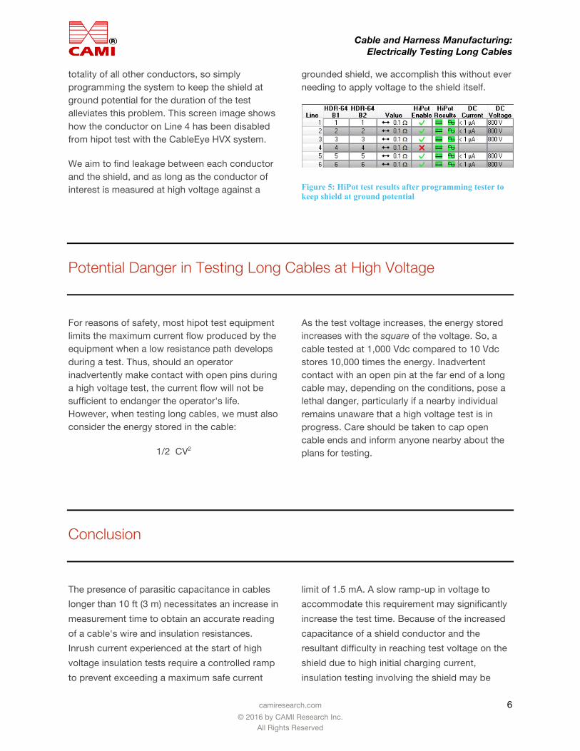
totality of all other conductors, so simply programming the system to keep the shield at ground potential for the duration of the test alleviates this problem. This screen image shows how the conductor on Line 4 has been disabled from hipot test with the CableEye HVX system.
We aim to find leakage between each conductor and the shield, and as long as the conductor of interest is measured at high voltage against a
grounded shield, we accomplish this without ever needing to apply voltage to the shield itself.
Figure 5: HiPot test results after programming tester to keep shield at ground potential
Potential Danger in Testing Long Cables at High Voltage
For reasons of safety, most hipot test equipment limits the maximum current flow produced by the equipment when a low resistance path develops during a test. Thus, should an operator inadvertently make contact with open pins during a high voltage test, the current flow will not be sufficient to endanger the operator's life. However, when testing long cables, we must also consider the energy stored in the cable:
1/2 CV2
As the test voltage increases, the energy stored increases with the square of the voltage. So, a cable tested at 1,000 Vdc compared to 10 Vdc stores 10,000 times the energy. Inadvertent contact with an open pin at the far end of a long cable may, depending on the conditions, pose a lethal danger, particularly if a nearby individual remains unaware that a high voltage test is in progress. Care should be taken to cap open cable ends and inform anyone nearby about the plans for testing.
Conclusion
The presence of parasitic capacitance in cables longer than 10 ft (3 m) necessitates an increase in measurement time to obtain an accurate reading of a cable's wire and insulation resistances. Inrush current experienced at the start of high voltage insulation tests require a controlled ramp to prevent exceeding a maximum safe current
limit of 1.5 mA. A slow ramp-up in voltage to accommodate this requirement may significantly increase the test time. Because of the increased capacitance of a shield conductor and the resultant difficulty in reaching test voltage on the shield due to high initial charging current, insulation testing involving the shield may be
Cable and Harness Manufacturing: Electrically Testing Long Cables
camiresearch.com 7 © 2016 by CAMI Research Inc.
All Rights Reserved
limited to wire-to-shield only, and application of voltage shield-to-wire eliminated without loss of confidence in the shield insulation. Great care must be exercised by the test technician during high voltage tests on long cables to avoid electric shock during testing because of potentially lethal discharge current that may far exceed the current
produced by the tester itself. To ensure accurate, timely, and safe electrical measurements of wire and insulation resistance in long cables, hipot testers need to offer controls to set ramp rate, dwell time, and selectively exclude particular conductors, such as the shield, from application of high voltage.
The Author Christopher E. Strangio is the President and founder of CAMI Research and holds degrees in Electrical Engineering from Villanova University and MIT. A lecturer at the MIT Lowell Institute for twenty years, and author/presenter of a microprocessors multimedia course for the MIT Center for Advanced Engineering Study, he has been awarded two patents, developed the CableEye PC-based cable & harness test system, and is a senior member of the IEEE.
Cable and Harness Manufacturing: Electrically Testing Long Cables
camiresearch.com 8 © 2016 by CAMI Research Inc.
All Rights Reserved
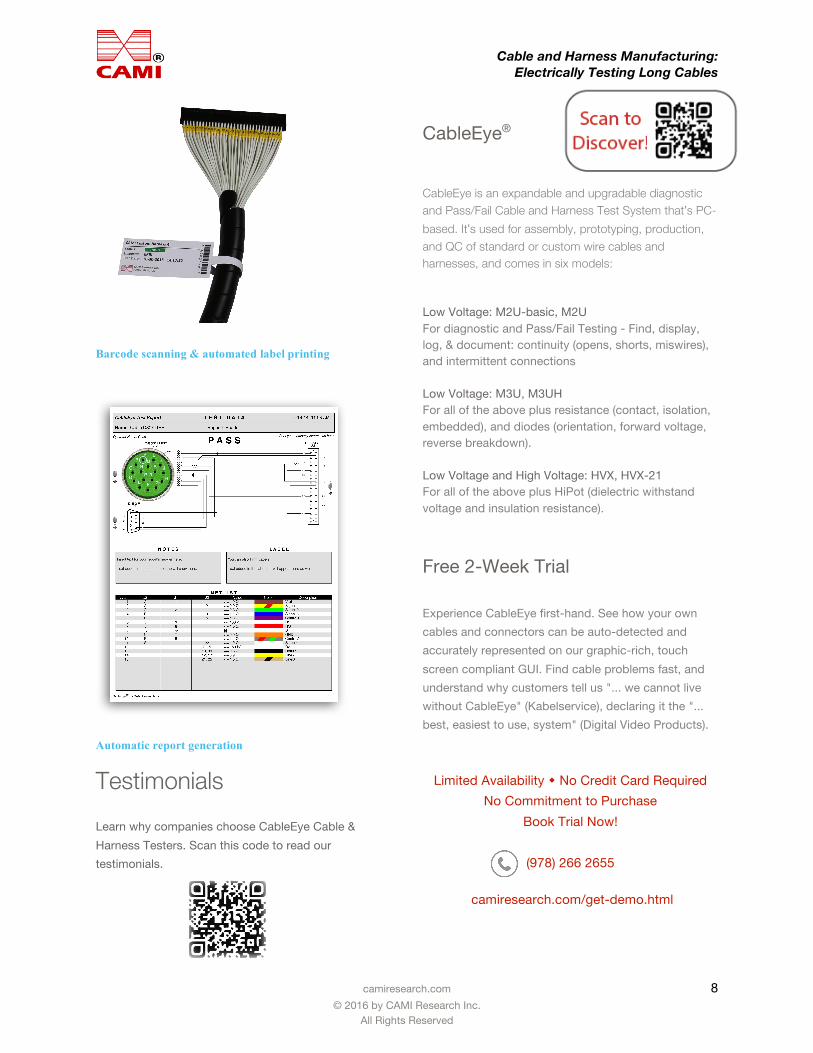
Automatic report generation Testimonials Learn why companies choose CableEye Cable & Harness Testers. Scan this code to read our testimonials.
CableEye® CableEye is an expandable and upgradable diagnostic and Pass/Fail Cable and Harness Test System that’s PC-based. It’s used for assembly, prototyping, production, and QC of standard or custom wire cables and harnesses, and comes in six models:
Low Voltage: M2U-basic, M2U For diagnostic and Pass/Fail Testing - Find, display, log, & document: continuity (opens, shorts, miswires), and intermittent connections
Low Voltage: M3U, M3UH For all of the above plus resistance (contact, isolation, embedded), and diodes (orientation, forward voltage, reverse breakdown).
Low Voltage and High Voltage: HVX, HVX-21 For all of the above plus HiPot (dielectric withstand voltage and insulation resistance).
Free 2-Week Trial
Experience CableEye first-hand. See how your own cables and connectors can be auto-detected and accurately represented on our graphic-rich, touch screen compliant GUI. Find cable problems fast, and understand why customers tell us "... we cannot live without CableEye" (Kabelservice), declaring it the "... best, easiest to use, system" (Digital Video Products).
Limited Availability w No Credit Card Required
No Commitment to Purchase Book Trial Now!
(978) 266 2655
camiresearch.com/get-demo.html
Barcode scanning & automated label printing