Electrical circuit models of protein structure · Electrical circuit models of protein structure...
28
1 Electrical circuit models of protein structure A framework for the analysis, classification, and synthesis of protein shapes G. Sampath Department of Bioinformatics and Computer Science University of the Sciences in Philadelphia
Transcript of Electrical circuit models of protein structure · Electrical circuit models of protein structure...
1
Electrical circuit models of protein structure
A framework for the analysis, classification, and synthesis of protein shapes
G. SampathDepartment of Bioinformatics and Computer Science
University of the Sciences in Philadelphia
2
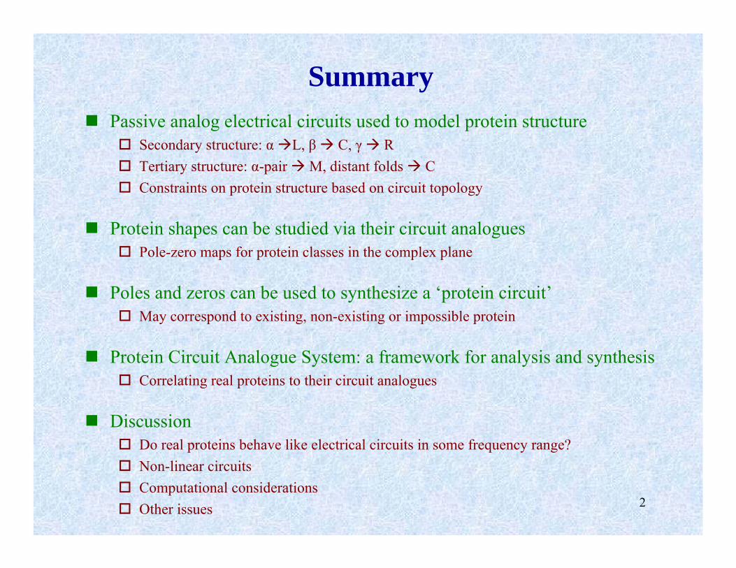
SummaryPassive analog electrical circuits used to model protein structure
Secondary structure: α L, β C, γ RTertiary structure: α-pair M, distant folds CConstraints on protein structure based on circuit topology
Protein shapes can be studied via their circuit analoguesPole-zero maps for protein classes in the complex plane
Poles and zeros can be used to synthesize a ‘protein circuit’May correspond to existing, non-existing or impossible protein
Protein Circuit Analogue System: a framework for analysis and synthesisCorrelating real proteins to their circuit analogues
DiscussionDo real proteins behave like electrical circuits in some frequency range?Non-linear circuitsComputational considerationsOther issues
3
Modeling a complex system via its analogue in another domain
Examples• Hodgkin-Huxley model
Nonlinear RC transmission line model of nerve signal transmission
• RLC circuit models in thermodynamics and quantum phenomena
Callen circuitQuantum billiards
• Hopfield nets in computationNeural nets for computationAssociative memory
4
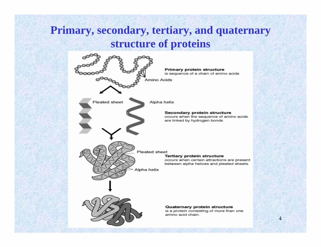
Primary, secondary, tertiary, and quaternary structure of proteins
5
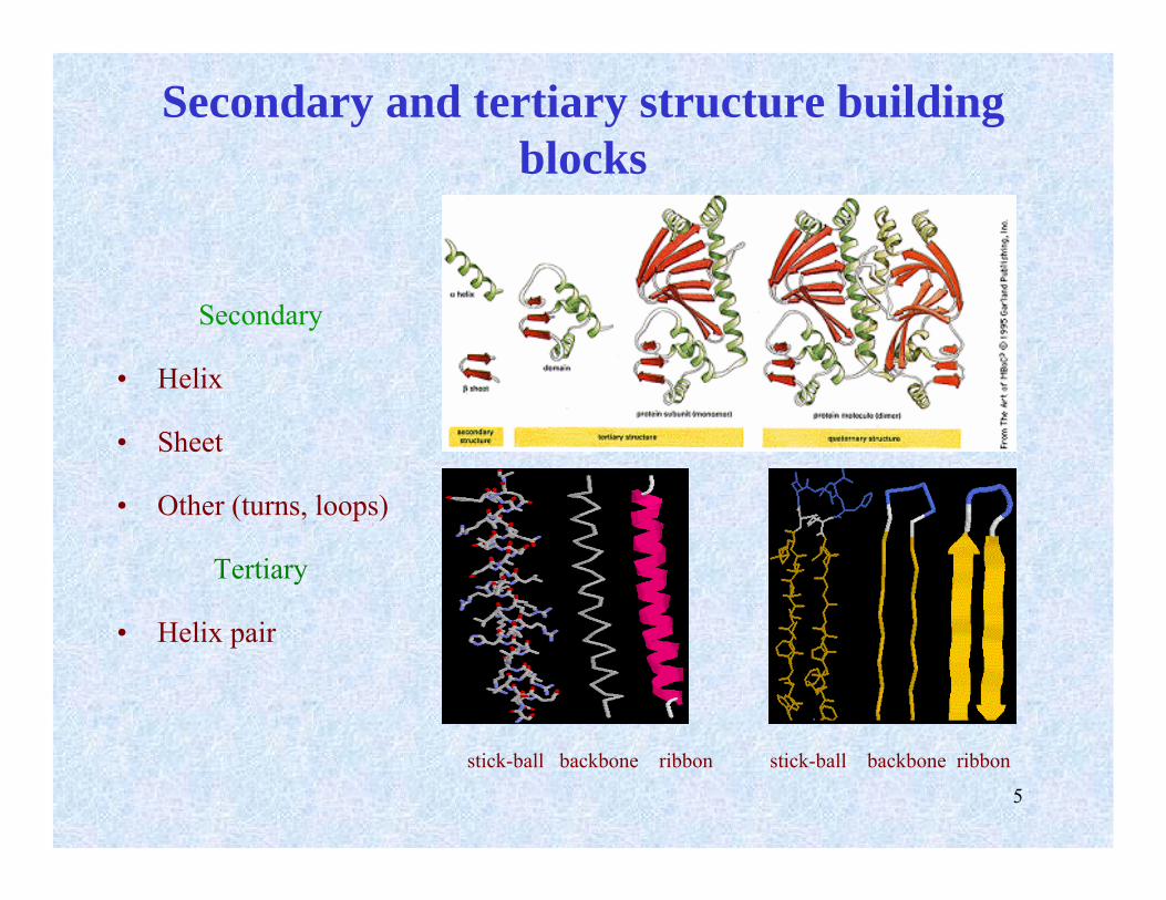
Secondary and tertiary structure building blocks
Secondary
• Helix
• Sheet
• Other (turns, loops)
Tertiary
• Helix pair
stick-ball backbone ribbon stick-ball backbone ribbon
6
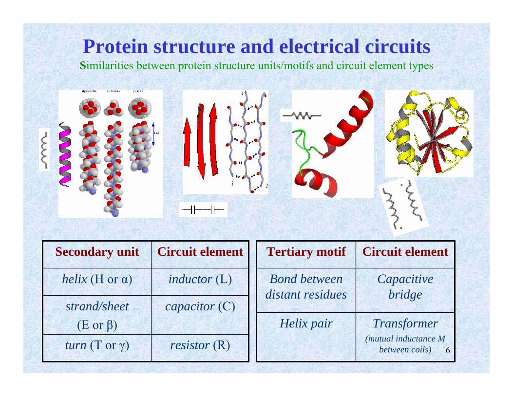
Protein structure and electrical circuitsSimilarities between protein structure units/motifs and circuit element types
Circuit elementSecondary unit
resistor (R)turn (T or γ)
capacitor (C)strand/sheet(E or β)
inductor (L)helix (H or α)
Transformer(mutual inductance M
between coils)
Helix pair
Capacitive bridge
Bond between distant residues
Circuit elementTertiary motif
7
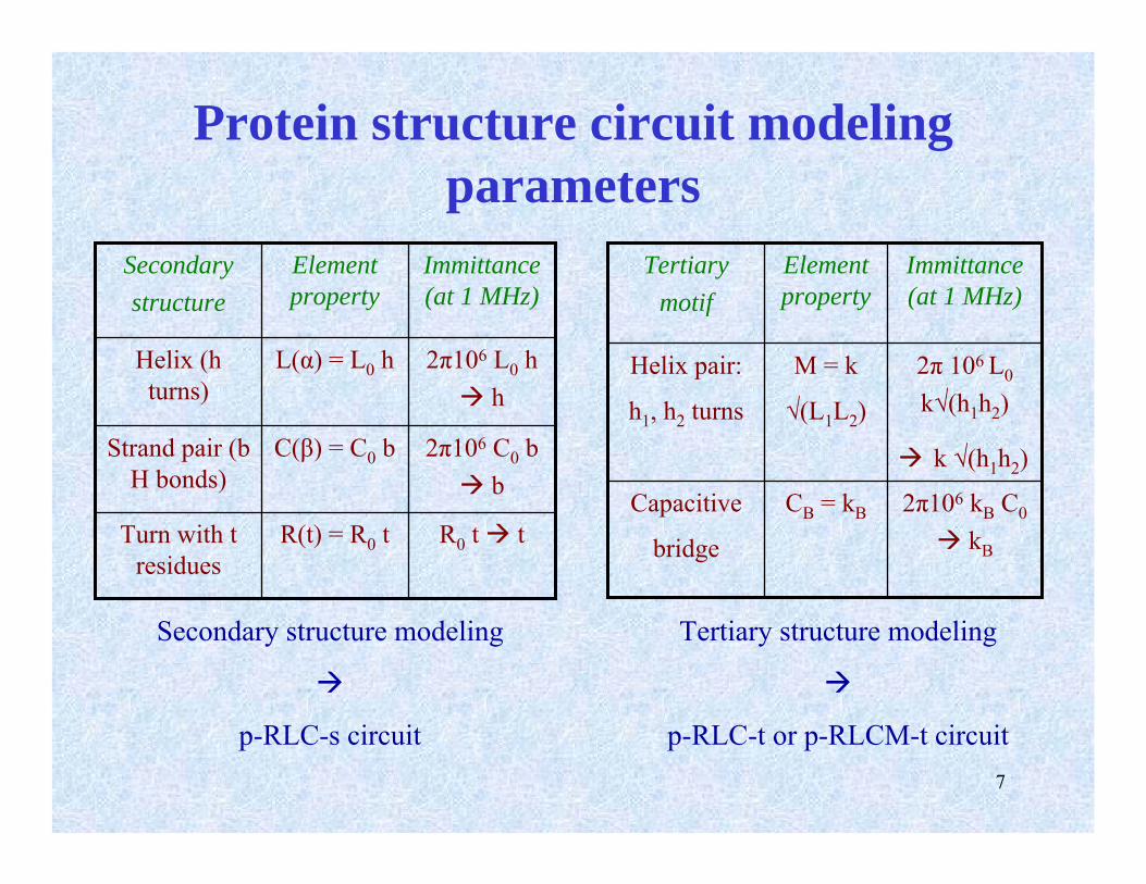
Protein structure circuit modeling parameters
R0 t tR(t) = R0 tTurn with t residues
2π106 C0 bb
C(β) = C0 bStrand pair (b H bonds)
2π106 L0 hh
L(α) = L0 hHelix (h turns)
Immittance(at 1 MHz)
Element property
Secondary structure
2π106 kB C0
kB
CB = kBCapacitive
bridge
2π 106 L0
k√(h1h2)
k √(h1h2)
M = k
√(L1L2)
Helix pair:
h1, h2 turns
Immittance(at 1 MHz)
Element property
Tertiary motif
Secondary structure modeling
p-RLC-s circuit
Tertiary structure modeling
p-RLC-t or p-RLCM-t circuit
8
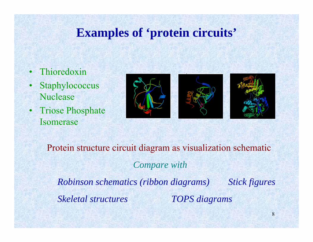
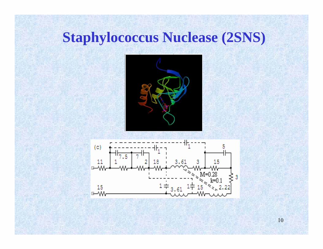
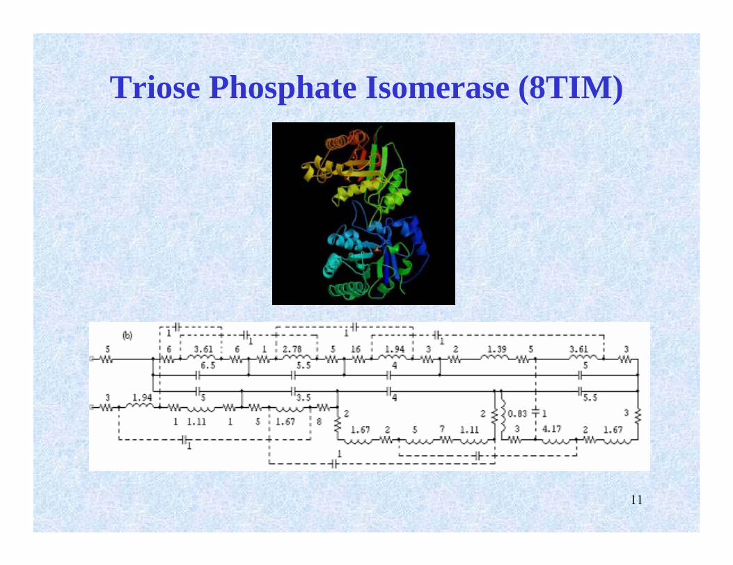
Examples of ‘protein circuits’
• Thioredoxin• Staphylococcus
Nuclease• Triose Phosphate
Isomerase
Protein structure circuit diagram as visualization schematic
Compare with
Robinson schematics (ribbon diagrams) Stick figures
Skeletal structures TOPS diagrams
9
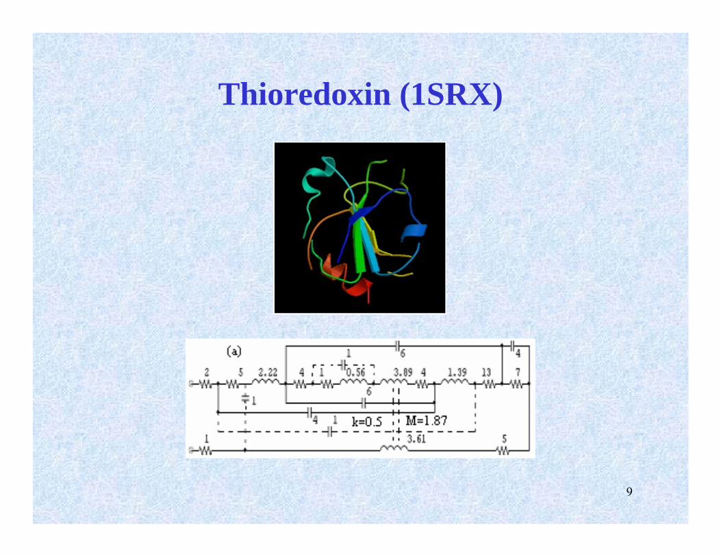
Thioredoxin (1SRX)
10
Staphylococcus Nuclease (2SNS)
11
Triose Phosphate Isomerase (8TIM)
12
Structural properties/shape of protein ? Properties of its p-RLC(M) circuit
• Analytical approach– Search for and compare compatible characteristics in the two domains– Classification procedures based on those characteristics
• Synthetic approach– Search for protein structure and shape based on designed RLC(M) circuits– Consider circuits that are known and/or widely used in circuit applications
Such a search may lead to three possibilities– a known protein structure,– one that has not been observed in nature– one that is perhaps physically or chemically impossible
• Folding studies– Circuit component sizes and distances used to compute possible 3-D shapes of a
protein for a given RLC(M) circuit.
From proteins to circuits and back
13
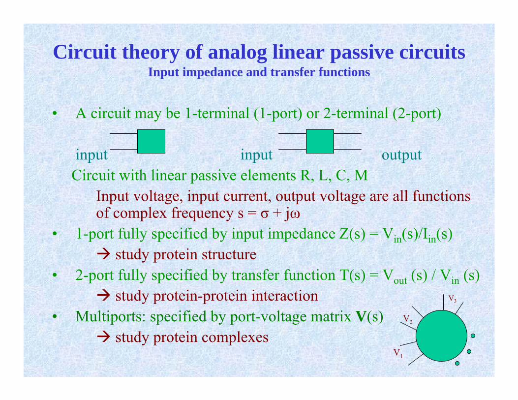
• A circuit may be 1-terminal (1-port) or 2-terminal (2-port)
input input outputCircuit with linear passive elements R, L, C, M
Input voltage, input current, output voltage are all functions of complex frequency s = σ + jω
• 1-port fully specified by input impedance Z(s) = Vin(s)/Iin(s)study protein structure
• 2-port fully specified by transfer function T(s) = Vout (s) / Vin (s)study protein-protein interaction V3
• Multiports: specified by port-voltage matrix V(s) V2
study protein complexesV1
Circuit theory of analog linear passive circuitsInput impedance and transfer functions
14
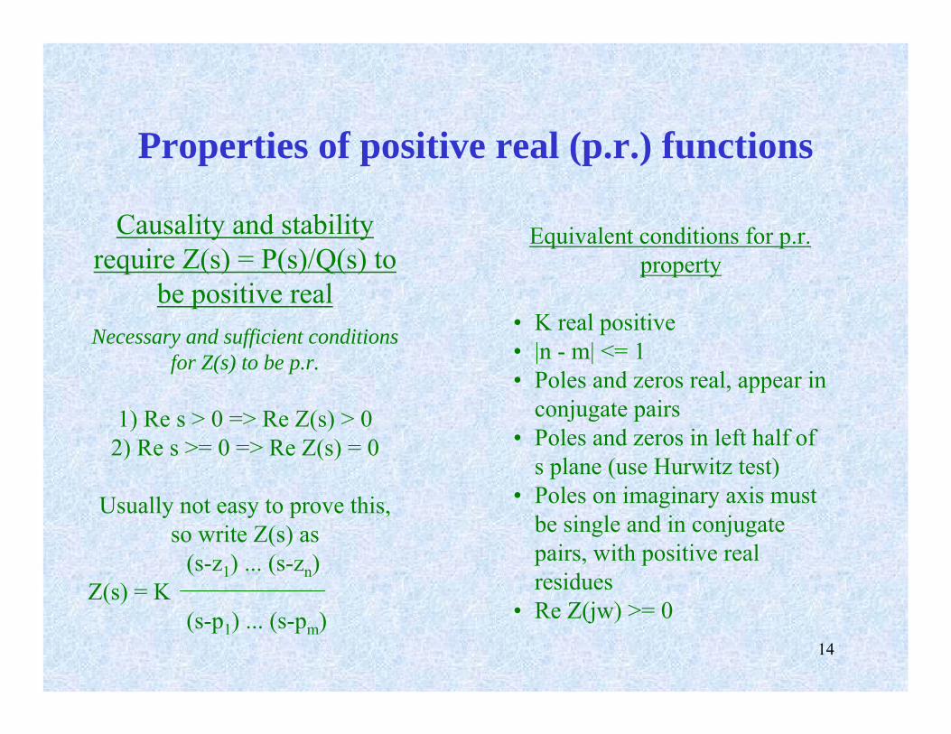
Properties of positive real (p.r.) functions
Causality and stability require Z(s) = P(s)/Q(s) to
be positive realNecessary and sufficient conditions
for Z(s) to be p.r.
1) Re s > 0 => Re Z(s) > 0 2) Re s >= 0 => Re Z(s) = 0
Usually not easy to prove this,so write Z(s) as
(s-z1) ... (s-zn)Z(s) = K
(s-p1) ... (s-pm)
Equivalent conditions for p.r. property
• K real positive• |n - m| <= 1• Poles and zeros real, appear in
conjugate pairs• Poles and zeros in left half of
s plane (use Hurwitz test)• Poles on imaginary axis must
be single and in conjugate pairs, with positive real residues
• Re Z(jw) >= 0
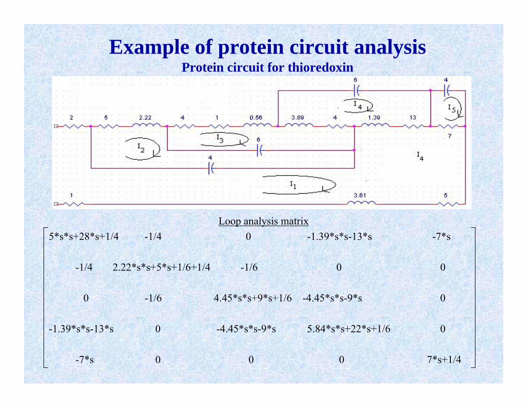
Example of protein circuit analysisProtein circuit for thioredoxin
Loop analysis matrix5*s*s+28*s+1/4 -1/4 0 -1.39*s*s-13*s -7*s
-1/4 2.22*s*s+5*s+1/6+1/4 -1/6 0 0
0 -1/6 4.45*s*s+9*s+1/6 -4.45*s*s-9*s 0
-1.39*s*s-13*s 0 -4.45*s*s-9*s 5.84*s*s+22*s+1/6 0
-7*s 0 0 0 7*s+1/4
16
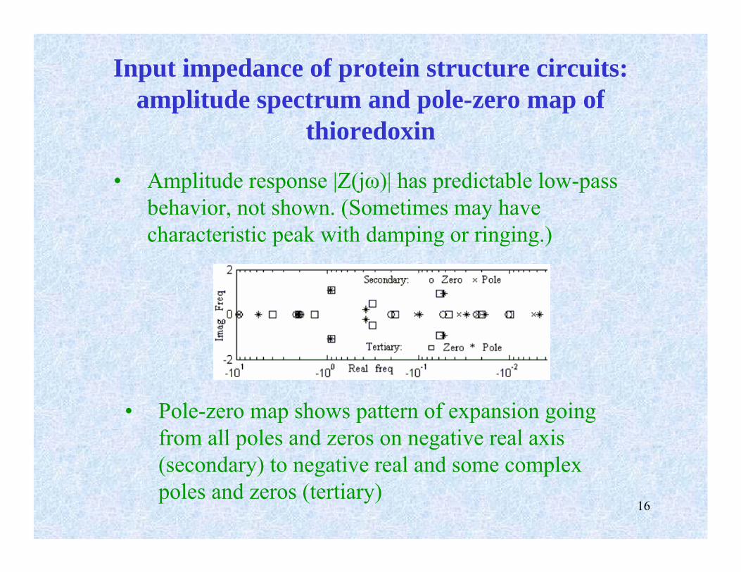
Input impedance of protein structure circuits: amplitude spectrum and pole-zero map of
thioredoxin
• Pole-zero map shows pattern of expansion going from all poles and zeros on negative real axis (secondary) to negative real and some complex poles and zeros (tertiary)
• Amplitude response |Z(jω)| has predictable low-pass behavior, not shown. (Sometimes may have characteristic peak with damping or ringing.)
17
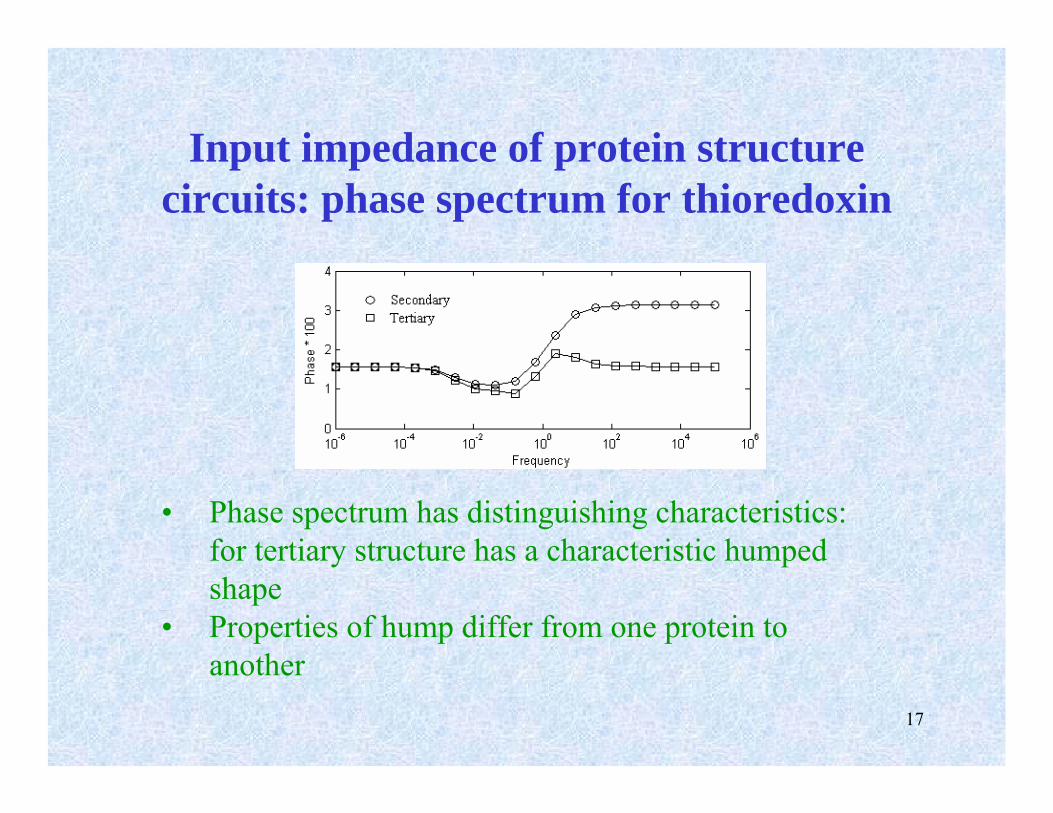
Input impedance of protein structure circuits: phase spectrum for thioredoxin
• Phase spectrum has distinguishing characteristics: for tertiary structure has a characteristic humped shape
• Properties of hump differ from one protein to another
18
Protein pole-zero maps
• One can consider mapping proteins in protein families to the corresponding poles and zeros at different levels: secondary, tertiary and quaternary.
• Conversely, one can look at the pole-zero distribution of a set of proteins and use the poles and zeros to group proteins.
• This leads to a classification scheme that can use training schemes similar to those used in neural-net-based methods.
• Conversely one could specify a set of poles and zeros from which it could be determined if there is a corresponding protein.
19
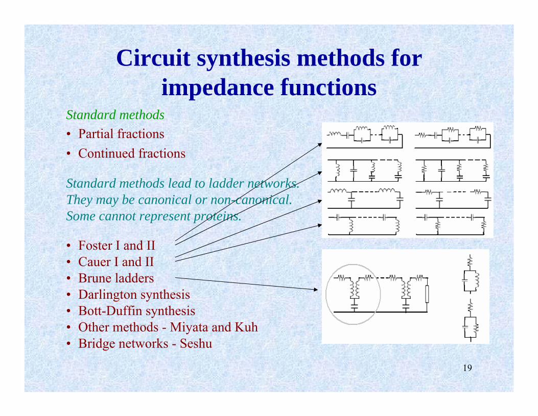
Circuit synthesis methods for impedance functions
Standard methods• Partial fractions• Continued fractions
Standard methods lead to ladder networks.They may be canonical or non-canonical.Some cannot represent proteins.
• Foster I and II• Cauer I and II• Brune ladders• Darlington synthesis• Bott-Duffin synthesis• Other methods - Miyata and Kuh• Bridge networks - Seshu
20
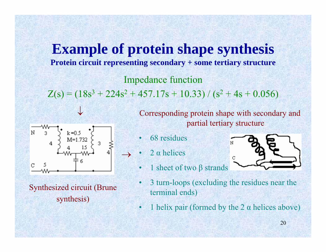
Corresponding protein shape with secondary and partial tertiary structure
• 68 residues
• 2 α helices
• 1 sheet of two β strands
• 3 turn-loops (excluding the residues near the terminal ends)
• 1 helix pair (formed by the 2 α helices above)
Example of protein shape synthesisProtein circuit representing secondary + some tertiary structure
Impedance functionZ(s) = (18s3 + 224s2 + 457.17s + 10.33) / (s2 + 4s + 0.056)
Synthesized circuit (Brunesynthesis)
↓
→

21
Variations/restrictions on protein circuit topology
Secondary structure comes from linear sequence of amino acids
Elements in RLC(M) circuit cannot be arbitrarily connected
• p-RLC-s circuit can’t be Foster II, Cauer II, bridge circuit, Bott-Duffin.• If strands form sheet in primary sequence order (as in some barrels)
then β-α- β motif can be represented by Foster I or Cauer I. • When turns are present inductors may be replaced with lossy ones:
L → series LR, RL or LRL R ≡ turn or loop• Can cascade different forms in successive stages.• A-type (but not B-type) Brune sections can be used for tertiary
structure with helix pairs.• In most cases, the dual network does not exist. In particular, non-
planar circuits cannot have duals.• In general, network realizing a given impedance function is not unique;
some of these equivalent networks may or may not correspond to aprotein structure.
22
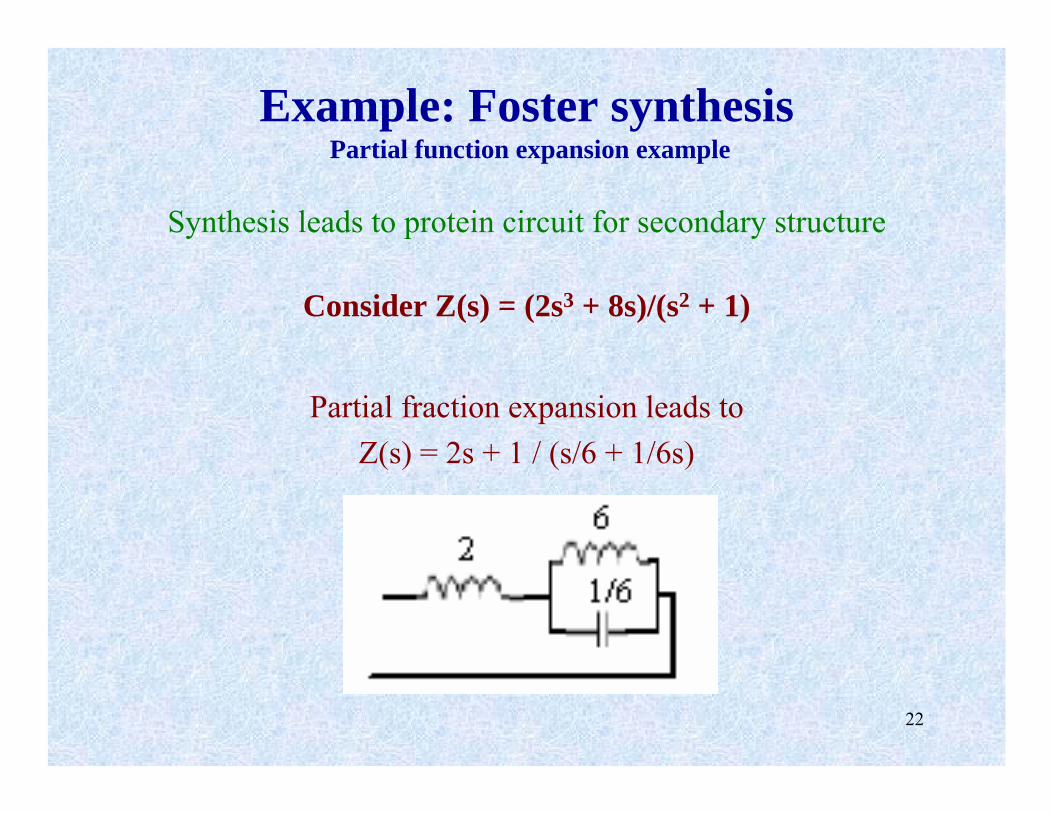
Example: Foster synthesisPartial function expansion example
Synthesis leads to protein circuit for secondary structure
Consider Z(s) = (2s3 + 8s)/(s2 + 1)
Partial fraction expansion leads toZ(s) = 2s + 1 / (s/6 + 1/6s)
23
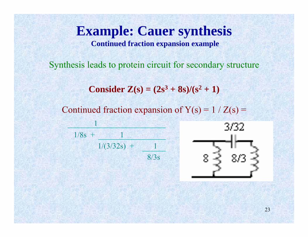
Example: Cauer synthesisContinued fraction expansion example
Synthesis leads to protein circuit for secondary structure
Consider Z(s) = (2s3 + 8s)/(s2 + 1)
Continued fraction expansion of Y(s) = 1 / Z(s) =1
1/8s + 11/(3/32s) + 1
8/3s

24
Example: Brune synthesisTransformer-based synthesis example
Leads to protein circuit for secondary structure and partial tertiary structure
Consider Z(s) = (8s2 +s + 4)/(24s3 + 11s2 + 20s + 1)
• 68 residues
• 2 α helices
• 1 sheet of two β strands
• 3 turn-loops (excluding the residues near the terminal ends)
• 1 helix pair (formed by the 2 α helices above)
25
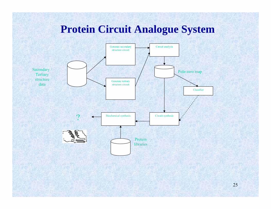
Generate secondary structure circuit
Generate tertiary structure circuit
Circuit analysis
Classifier
Circuit synthesisBiochemical synthesis
Protein Circuit Analogue System
Secondary / Tertiary structure
data
Pole-zero map
Protein libraries
?
26
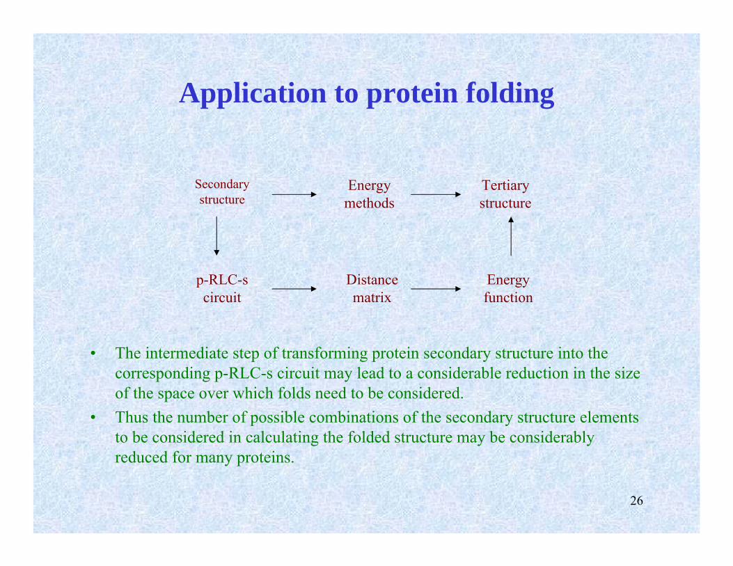
Application to protein folding
• The intermediate step of transforming protein secondary structure into the corresponding p-RLC-s circuit may lead to a considerable reduction in the size of the space over which folds need to be considered.
• Thus the number of possible combinations of the secondary structure elements to be considered in calculating the folded structure may be considerably reduced for many proteins.
Secondary structure
Energy methods
Tertiary structure
p-RLC-s circuit
Distance matrix
Energy function
27
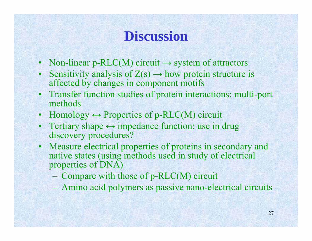
Discussion
• Non-linear p-RLC(M) circuit → system of attractors• Sensitivity analysis of Z(s) → how protein structure is
affected by changes in component motifs• Transfer function studies of protein interactions: multi-port
methods• Homology ↔ Properties of p-RLC(M) circuit• Tertiary shape ↔ impedance function: use in drug
discovery procedures?• Measure electrical properties of proteins in secondary and
native states (using methods used in study of electrical properties of DNA)– Compare with those of p-RLC(M) circuit– Amino acid polymers as passive nano-electrical circuits
28
Circuit theory bibliography
• C. A. Desoer and E. S. Kuh. Basic Circuit Theory. (1969)• M. E. Van Valkenburg. Modern Network Synthesis. (1960)• L. Weinberg. Network Analysis and Synthesis. (1962)• G.C.Temes, J.W.LaPatra. Intro to Circuit Synthesis and Design. (1977)• H.-W. Fink, C. Schönenberger. Nature 398, 407-410. (1999)• P. Dietz and M. Reif. PNAS 103 (5), 1244-7. (2006)
CreditsSeveral figures reproduced/adapted from various sources on the web