Eikon Arké e Plana 20430 19430 16915 14430 · Πρότυπα en 50090-2-2, en 50428....
6
Viale Vicenza, 14 36063 Marostica VI - Italy www.vimar.com 49400397D0 02 1611 Eikon 20430 Arké 19430 Idea 16915 Plana 14430 Termostato electrónico para el control de la temperatura ambiente de 2 zonas independientes (calefacción y aire acondicionado), estándar KNX, 1 salida de relé NO 4 A 24 V~, 1 entrada para sensor de temperatura 20432-19432-14432, 1 entrada digital programable - 2 módulos. VISTA FRONTAL. • Pulsador A: disminución de la temperatura de consigna. • Pulsador B: aumento de la temperatura de consigna. • Pulsador C (pulsación corta): selección del termostato a visualizar/controlar: - termostato A (visualización y control); - termostato B, si está activado; icono ext encendido (visualización y control); - temperatura sondas KNX 1÷8 (si las hay, solo visualización); - sonda NTC interna del termostato A (visualización); - sonda NTC externa conectada al borne del termostato (si la hay, solo visualización). • Pulsador C (pulsación larga): visualización del modo de funcionamiento. • Pulsador D: aumento/disminución de la velocidad del ventilador-convector. ext PANTALLA. Temperatura ambiente Unidad de medida (Celsius/Fahrenheit) Aire acondicionado/ Calefacción Velocidad del ventilador-convector Función cliente fuera de la habitación (Stand-by) Antihielo Instalación apagada Temperatura de confort que el cliente cambió de punto de ajuste por defecto Economy Dispositivo bloqueado (no controlable localmente) Termostato B activado El termostato es adecuado para controlar la temperatura ambiente (calefacción y aire acondicio- nado) y puede interactuar con otros termostatos (cuyas temperaturas medidas se pueden utilizar para determinar la temperatura “ponderada”) y con un centro de supervisión (PC en recepción o sala técnica donde esté instalado, por ejemplo, el software Well-contact Suite). El dispositivo puede controlar 2 zonas climáticas de forma totalmente independiente; práctica- mente es como si constara de dos termostatos independientes que controlan una zona cada uno (termostatos A y B). El termostato está provisto de un relé programable como NC o NO, que se puede utilizar para uso genérico (encendido de luces/cierre de electroválvula de zona/ activación de secador de toallas, etc.) o para el control de la velocidad 1 del ventilador-convector controlado por el termostato A (o bien por el termostato B). Además, dispone de una entrada digital programable como NC o NO que se puede utilizar para aplicaciones (por ejemplo, la detección de una ventana abierta) u otros usos generales tanto para uno como para ambos termostatos A/B. El dispositivo cuenta con una pantalla y cuatro pulsadores frontales para determinar la tempera- tura de consigna y la velocidad del ventilador-convector. CARACTERÍSTICAS. • Tensión de alimentación: BUS 29 V SELV • Consumo: 10 mA • Bornes: - Bus TP; - Entrada digital para contactos NO o NC (libre de potencial, SELV); - Salida de relé NO ( 24 V~ SELV 4 A cos 1; 24 V~ SELV 2 A cos 0,6); • Temperatura de funcionamiento: -5 °C - +45 °C (uso interior); • Clasificación ErP (Reg. UE 811/2013): clase I, contribución 1%; ±0,5 °C entre 15 °C y 30 °C • Precisión de la lectura: ±0,8 °C en los extremos • Este aparato contiene solo circuitos SELV, que se deben mantener separados de los circuitos con tensiones peligrosas. • Sensores de temperatura controlables con el termostato 20430-19430-16915-14430. - NTC interna - Posibilidad de conectar NTC externa art. 20432-19432-14432 - Posibilidad de utilizar los valores de temperatura enviados al bus por 8 sondas KNX de temperatura (dato de tipo DPT_Value_Temp). - Longitud máxima del cable de conexión de la NTC externa: 60 m. Utilice un cable trenzado con sección mínima de 0.5 mm 2 (art. 01840) • Temperatura de referencia Por cada termostato A y B la temperatura de referencia para controlar el clima es la media ponderada entre todas las fuentes de temperatura disponibles (si las hay): - NTC interna - NTC externa art. 20432-19432-14432 - desde el bus (temperatura sondas KNX 1÷8) FUNCIONAMIENTO. El termostato, es decir, la dirección física, los parámetros, el funcionamiento, etc., se configura mediante el software ETS. Si en el termostato se carga un software ETS incorrecto, el led rojo, situado en la parte poste- rior del dispositivo, parpadea y en la pantalla parpadearán todos los segmentos LCD (error “Devicetype”). Para restablecer la configuración deseada, hay que cargar el software ETS correcto en el dispositivo. Con las teclas frontales, el usuario puede modificar la consigna de la temperatura y la velocidad del ventilador-convector; al modificar estos parámetros se fuerza el termostato al funcionamiento manual. USO DEL TERMOSTATO. Mediante el termostato se puede programar: • la temperatura de consigna en la habitación (la modificación se puede efectuar únicamente dentro de ciertos límites programados por el centro de control o recepción, etc.); • la velocidad del ventilador-convector. Para variar la temperatura, pulse 2 veces la tecla + o -: • cuando se pulsa por primera vez, la pantalla muestra la temperatura actualmente programada; • cuando se pulsa por segunda vez, se empieza a aumentar o disminuir el valor visualizado. La selección del termostato B se realiza con la tecla F. IMPORTANTE: longitud máxima del cable para la conexión de las entradas = 30 m. Nota: durante la fase de instalación se deben prever unos cables de conexión cuya longitud sea adecuada para poder extraer el dispositivo de su caja empotrada y, así, poder acceder al pulsador de configuración. NORMAS DE INSTALACIÓN. El aparato se ha de instalar en conformidad con las disposiciones sobre material eléctrico vigentes en el país. CONFORMIDAD NORMATIVA. Directiva EMC. Normas EN 50090-2-2 y EN 50428. CONEXIONES. Línea BUS Entrada común Relè C NO Entrada LED PULSADOR DE CONFIGURACIÓN Entrada para NTC externa THERMOSTAT OFF A B C D OFF A B C D OFF A B C D Eikon OFF THERMOSTAT F A B C D Arké Idea Plana
Transcript of Eikon Arké e Plana 20430 19430 16915 14430 · Πρότυπα en 50090-2-2, en 50428....
Viale Vicenza, 1436063 Marostica VI - Italy
www.vimar.com49400397D0 02 1611
Eikon
20430Arké
19430Idea
16915Plana
14430
Termostato electrónico para el control de la temperatura ambiente de 2 zonas independientes (calefacción y aire acondicionado), estándar KNX, 1 salida de relé NO 4 A 24 V~, 1 entrada para sensor de temperatura 20432-19432-14432, 1 entrada digital programable - 2 módulos.
VISTA FRONTAL.
• Pulsador A: disminución de la temperatura de consigna.• Pulsador B: aumento de la temperatura de consigna.• Pulsador C (pulsación corta): selección del termostato a visualizar/controlar:
- termostato A (visualización y control);- termostato B, si está activado; icono ext encendido (visualización y control);- temperatura sondas KNX 1÷8 (si las hay, solo visualización);- sonda NTC interna del termostato A (visualización);- sonda NTC externa conectada al borne del termostato (si la hay, solo visualización).
• Pulsador C (pulsación larga): visualización del modo de funcionamiento.• Pulsador D: aumento/disminución de la velocidad del ventilador-convector.
ext
PANTALLA.
Temperatura ambienteUnidad de medida (Celsius/Fahrenheit)
Aire acondicionado/Calefacción
Velocidad del ventilador-convector
Función cliente fuera de la habitación (Stand-by)
Antihielo
Instalación apagada
Temperatura de confort que el cliente cambió de punto de ajuste por defecto
Economy
Dispositivo bloqueado (no controlable localmente)
Termostato B activado
El termostato es adecuado para controlar la temperatura ambiente (calefacción y aire acondicio-nado) y puede interactuar con otros termostatos (cuyas temperaturas medidas se pueden utilizar para determinar la temperatura “ponderada”) y con un centro de supervisión (PC en recepción o sala técnica donde esté instalado, por ejemplo, el software Well-contact Suite). El dispositivo puede controlar 2 zonas climáticas de forma totalmente independiente; práctica-mente es como si constara de dos termostatos independientes que controlan una zona cada uno (termostatos A y B). El termostato está provisto de un relé programable como NC o NO, que se puede utilizar para uso genérico (encendido de luces/cierre de electroválvula de zona/activación de secador de toallas, etc.) o para el control de la velocidad 1 del ventilador-convector controlado por el termostato A (o bien por el termostato B). Además, dispone de una entrada digital programable como NC o NO que se puede utilizar para aplicaciones (por ejemplo, la detección de una ventana abierta) u otros usos generales tanto para uno como para ambos termostatos A/B.El dispositivo cuenta con una pantalla y cuatro pulsadores frontales para determinar la tempera-tura de consigna y la velocidad del ventilador-convector.
CARACTERÍSTICAS.• Tensión de alimentación: BUS 29 V SELV• Consumo: 10 mA• Bornes:- Bus TP;- Entrada digital para contactos NO o NC (libre de potencial, SELV);- Salida de relé NO ( 24 V~ SELV 4 A cos 1; 24 V~ SELV 2 A cos 0,6);• Temperatura de funcionamiento: -5 °C - +45 °C (uso interior);• Clasificación ErP (Reg. UE 811/2013): clase I, contribución 1%; ±0,5 °C entre 15 °C y 30 °C• Precisión de la lectura:
±0,8 °C en los extremos• Este aparato contiene solo circuitos SELV, que se deben mantener separados de los circuitos
con tensiones peligrosas.
• Sensores de temperatura controlables con el termostato 20430-19430-16915-14430.- NTC interna- Posibilidad de conectar NTC externa art. 20432-19432-14432- Posibilidad de utilizar los valores de temperatura enviados al bus por 8 sondas KNX de
temperatura (dato de tipo DPT_Value_Temp).- Longitud máxima del cable de conexión de la NTC externa: 60 m. Utilice un cable trenzado
con sección mínima de 0.5 mm2 (art. 01840)
• Temperatura de referenciaPor cada termostato A y B la temperatura de referencia para controlar el clima es la media ponderada entre todas las fuentes de temperatura disponibles (si las hay):- NTC interna- NTC externa art. 20432-19432-14432- desde el bus (temperatura sondas KNX 1÷8)
FUNCIONAMIENTO.El termostato, es decir, la dirección física, los parámetros, el funcionamiento, etc., se configura mediante el software ETS.Si en el termostato se carga un software ETS incorrecto, el led rojo, situado en la parte poste-rior del dispositivo, parpadea y en la pantalla parpadearán todos los segmentos LCD (error “Devicetype”).Para restablecer la configuración deseada, hay que cargar el software ETS correcto en el dispositivo. Con las teclas frontales, el usuario puede modificar la consigna de la temperatura y la velocidad del ventilador-convector; al modificar estos parámetros se fuerza el termostato al funcionamiento manual.
USO DEL TERMOSTATO.Mediante el termostato se puede programar: • la temperatura de consigna en la habitación (la modificación se puede efectuar únicamente dentro de ciertos límites programados por el centro de control o recepción, etc.); • la velocidad del ventilador-convector.
Para variar la temperatura, pulse 2 veces la tecla + o -:• cuando se pulsa por primera vez, la pantalla muestra la temperatura actualmente programada;• cuando se pulsa por segunda vez, se empieza a aumentar o disminuir el valor visualizado.La selección del termostato B se realiza con la tecla F.
IMPORTANTE: longitud máxima del cable para la conexión de las entradas = 30 m.
Nota: durante la fase de instalación se deben prever unos cables de conexión cuya longitud sea adecuada para poder extraer el dispositivo de su caja empotrada y, así, poder acceder al pulsador de configuración.
NORMAS DE INSTALACIÓN.El aparato se ha de instalar en conformidad con las disposiciones sobre material eléctrico vigentes en el país.
CONFORMIDAD NORMATIVA.Directiva EMC.Normas EN 50090-2-2 y EN 50428.
CONEXIONES.
Línea BUS
Entradacomún
Relè C NOEntrada
LED
PULSADOR DE CONFIGURACIÓN
Entrada para NTC externa
THERMOSTAT
OFF
A B C D
OFF
A B C D
OFF
A B C D
Eikon
OFF
THERMOSTAT
F
A B C D
Arké Idea Plana
Viale Vicenza, 1436063 Marostica VI - Italy
www.vimar.com49400397D0 02 1611
Eikon
20430Arké
19430Idea
16915Plana
14430
Ηλεκτρονικός θερμοστάτης για τον έλεγχο της θερμοκρασίας χώρου 2 ανεξάρτητων ζωνών (θέρμανση και κλιματισμός), βάσει του προτύπου KNX, 1 έξοδος ρελέ NO 4 A 24 V~, 1 είσοδος για αισθητήρα θερμοκρασίας 20432-19432-14432, 1 προγραμματιζόμενη ψηφιακή είσοδος - 2 μονάδες.
ΜΠΡΟΣΤΙΝΗ ΠΛΕΥΡΑ.
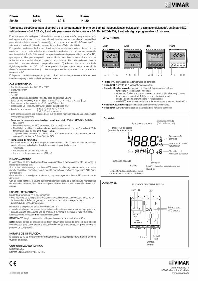
• Πλήκτρο A: μείωση της τιμής ρύθμισης της θερμοκρασίας.• Πλήκτρο B: αύξηση της τιμής ρύθμισης της θερμοκρασίας.• Πλήκτρο C (σύντομο πάτημα): επιλογή του θερμοστάτη για εμφάνιση/έλεγχο:
- θερμοστάτης A (εμφάνιση και έλεγχος),- θερμοστάτης B, εάν είναι ενεργοποιημένος, το εικονίδιο ext (εξωτερικός) είναι αναμμένο (εμφάνιση και έλεγχος),- θερμοκρασία αισθητήρων KNX 1÷8 (εάν υπάρχουν, μόνο εμφάνιση),- εσωτερικός αισθητήρας NTC στο θερμοστάτη A (εμφάνιση),- εξωτερικός αισθητήρας NTC συνδεδεμένος στον ακροδέκτη του θερμοστάτη (εάν υπάρχει, μόνο εμφάνιση).
• Πλήκτρο C (παρατεταμένο πάτημα): απεικόνιση του τρόπου λειτουργίας.• Πλήκτρο D: αύξηση/μείωση της ταχύτητας της μονάδας fan-coil.
ext
ΟΘΟΝΗ.
Θερμοκρασία χώρουΜονάδα μέτρησης (Κελσίου/Φαρενάιτ)
Κλιματισμός/Θέρμανση
Ταχύτητα μονάδας fan-coil
Λειτουργία αναμονής (ο πελάτης δεν βρίσκεται στο δωμάτιο)
Λειτουργία προστασίας από τον παγετό
Απενεργοποίηση εγκατάστασης
Θερμοκρασία Άνεση αλλάξει από τον πελάτη από το set-point από προεπιλογή
Λειτουργία Economy
Κλειδωμένη συσκευή (δεν μπορεί να ρυθμιστεί τοπικά)
Ενεργοποιημένος θερμοστάτης B
Ο θερμοστάτης είναι κατάλληλος για τον έλεγχο της θερμοκρασίας χώρου (θέρμανση και κλιματισμός) και μπορεί να συνδυαστεί με άλλους θερμοστάτες (οι μετρηθείσες θερμοκρασίες των οποίων μπορούν να χρησιμοποιηθούν για τον καθορισμό της «σταθμισμένης» θερμοκρασίας) και με ένα κέντρο ελέγχου (Η/Υ στην υποδοχή ή στο τεχνικό τμήμα όπου έχει εγκατασταθεί, για παράδειγμα, το λογισμικό Well-contact Suite). Η συσκευή μπορεί να ελέγχει 2 κλιματικές ζώνες με πλήρως ανεξάρτητο τρόπο. Στην πράξη, είναι σαν να αποτελείται από δύο ανεξάρτητους θερμοστάτες που ελέγχουν μία ζώνη ο καθένας (θερμοστάτες A και B). Ο θερμοστάτης διαθέτει ένα προγραμματιζόμενο ρελέ NC ή NO για γενική χρήση (ενεργοποίηση φώτων/κλείσιμο ηλεκτροβαλβίδας ζώνης/ενεργοποίηση ηλεκτρικού καλοριφέρ για πετσέτες, κλπ.) ή για τον έλεγχο της ταχύτητας 1 της μονάδας fan-coil που ελέγχεται από το θερμοστάτη A (ή εναλλακτικά από το θερμοστάτη B). Επίσης, διαθέτει μία προγραμματιζόμενη ψηφιακή είσοδο NC ή NO που μπορεί να χρησιμοποιηθεί για εφαρμογές.Η συσκευή διαθέτει οθόνη και τέσσερα πλήκτρα στο μπροστινό τμήμα για τον έλεγχο των τιμών ρύθμισης της θερμοκρασίας και της ταχύτητας της μονάδας fan-coil.
ΧΑΡΑΚΤΗΡΙΣΤΙΚΑ.• Τάση τροφοδοσίας: BUS 29 V SELV• Κατανάλωση: 10 mA• Ακροδέκτες:- bus TP;- ψηφιακή είσοδος για επαφή NO ή NC (χωρίς δυναμικό, SELV);- έξοδος ρελέ NO ( 24 V~ SELV 4 A cos 1, 24 V~ SELV 2 A cos 0,6);• Θερμοκρασία λειτουργίας: -5°C - +45°C (εσωτερική χρήση);• ErP Ταξινόμηση (Kανονισμό ΕΕ 811/2013): τάξη I, μερίδιο 1%; ± 0,5°C μεταξύ 15°C και 30°C• Ακρίβεια μέτρησης:
± 0,8°C στις οριακές τιμές• Η συσκευή αυτή περιλαμβάνει μόνο κυκλώματα SELV, τα οποία πρέπει να διαχωρίζονται
από κυκλώματα επικίνδυνης τάσης.• Αισθητήρες θερμοκρασίας που ελέγχονται από το θερμοστάτη 20430-19430-16915-14430.
- Εσωτερικός αισθητήρας NTC- Δυνατότητα σύνδεσης εξωτερικού αισθητήρα NTC, αρ. προϊόντος 20432-19432-14432- Δυνατότητα χρήσης των τιμών θερμοκρασίας που αποστέλλονται στο bus από 8
διαφορετικούς αισθητήρες θερμοκρασίας KNX (δεδομένα τύπου DPT_Value_Temp).- Μέγιστο μήκος καλωδίου σύνδεσης εξωτερικού αισθητήρα NTC: 60 m. Χρησιμοποιείτε
συνεστραμμένο καλώδιο με ελάχιστη διατομή 0,5 mm2 (αρ. προϊόντος 01840)• Θερμοκρασία αναφοράς.
Για καθέναν από τους δύο θερμοστάτες A και B, η θερμοκρασία αναφοράς για τον έλεγχο του κλιματισμού είναι η μέση σταθμισμένη τιμή μεταξύ όλων των διαθέσιμων πηγών θερμοκρασίας (εάν υπάρχουν):- Εσωτερικός αισθητήρας NTC- Εξωτερικός αισθητήρας NTC, αρ. προϊόντος 20432-19432-14432- από το bus (θερμοκρασία αισθητήρων KNX 1÷8)
ΛΕΙΤΟΥΡΓΙΑ.Η διαμόρφωση του θερμοστάτη, της διεύθυνσης, των παραμέτρων, της λειτουργίας του, κλπ. πραγματοποιείται μέσω του λογισμικού ETS.Σε περίπτωση φόρτωσης στο θερμοστάτη εσφαλμένης εφαρμογής ETS, αναβοσβήνει η κόκκινη λυχνία led στο πίσω μέρος της συσκευής, ενώ στην οθόνη αναβοσβήνουν όλες οι ενδείξεις LCD (σφάλμα «τύπου συσκευής»).Για αποκατάσταση της επιθυμητής διαμόρφωσης, φορτώστε στη συσκευή τη σωστή εφαρμογή ETS. Ο χρήστης μπορεί να τροποποιήσει, χρησιμοποιώντας τα πλήκτρα στο μπροστινό τμήμα, τις τιμές ρύθμισης της θερμοκρασίας και την ταχύτητα της μονάδας fan-coil. Όταν τροποποιηθούν οι παράμετροι αυτές, ο θερμοστάτης μεταβαίνει υποχρεωτικά στη χειροκίνητη λειτουργία.
ΧΡΗΣΗ ΤΟΥ ΘΕΡΜΟΣΤΑΤΗ.Μέσω του θερμοστάτη μπορείτε να ρυθμίσετε: • την τιμή θερμοκρασίας στο δωμάτιο (η τροποποίηση μπορεί να γίνει μόνο εντός συγκεκριμένων ορίων που καθορίζονται από το κέντρο ελέγχου ή την υποδοχή, κλπ.), • την ταχύτητα της μονάδας fan-coil.Για να τροποποιήσετε τη θερμοκρασία, πατήστε 2 φορές το πλήκτρο + ή το πλήκτρο -:• με το πρώτο πάτημα, στην οθόνη εμφανίζεται η τρέχουσα ρυθμισμένη θερμοκρασία,• με το δεύτερο πάτημα, ξεκινά η αύξηση/μείωση της εμφανιζόμενης τιμής.Ο θερμοστάτης B επιλέγεται με το πλήκτρο F. ΣΗΜΑΝΤΙΚΟ: Το μέγ. μήκος του καλωδίου για τη σύνδεση των εισόδων πρέπει να είναι 30 m.Σημείωση: Κατά τη φάση της εγκατάστασης, το μήκος σύνδεσης των καλωδίων πρέπει να είναι κατάλληλο, ώστε να είναι δυνατή η εξαγωγή της συσκευής από το κουτί χωνευτής εγκατάστασης για πρόσβαση στο πλήκτρο διαμόρφωσης.
ΚΑΝΟΝΙΣΜΟΙ ΕΓΚΑΤΑΣΤΑΣΗΣ.Η εγκατάσταση πρέπει να πραγματοποιείται σύμφωνα με τους ισχύοντες κανονισμούς εγκατάστασης ηλεκτρολογικού υλικού στη χώρα εγκατάστασης των προϊόντων.
ΣΥΜΜΟΡΦΩΣΗ ΜΕ ΤΑ ΠΡΟΤΥΠΑ.Οδηγία ΗΜΣ.Πρότυπα EN 50090-2-2, EN 50428.
ΣΥΝΔΕΣΕΙΣ.
Γραμμή BUS
Κοινή είσοδος Ρελέ
C NO Είσοδος
Λυχνία LED
ΠΛΗΚΤΡΟ ΔΙΑΜΟΡΦΩΣΗΣ
Είσοδος για αισθητήρα NTC θερμοκρασίας
THERMOSTAT
OFF
A B C D
OFF
A B C D
OFF
A B C D
Eikon
OFF
THERMOSTAT
F
A B C D
Arké Idea Plana
Viale Vicenza, 1436063 Marostica VI - Italy
www.vimar.com49400397D0 02 1611
Eikon
20430Arké
19430Idea
16915Plana
14430
Termostato elettronico per controllo temperatura ambiente di 2 zone indipendenti (riscaldamento e condizionamento), standard KNX, 1 uscita a relè NO 4 A 24 V~, 1 ingresso per sensore di temperatura 20432-19432-14432, 1 ingresso digitale programmabile - 2 moduli.
THERMOSTAT
OFF
A B C D
OFF
A B C D
OFF
A B C D
VISTA FRONTALE.
Eikon
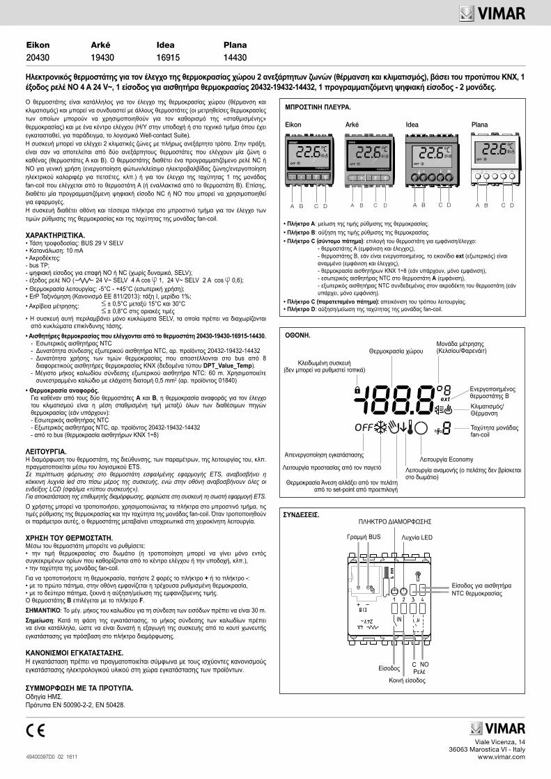
• Pulsante A: decremento del set-point della temperatura.• Pulsante B: incremento del set-point della temperatura.• Pulsante C (con pressione breve): selezione del termostato da visualizzare/controllare:
- termostato A (visualizzazione e controllo);- termostato B, se abilitato; icona ext accesa (visualizzazione e controllo);- temperatura sonde KNX 1÷8 (se presenti, solo visualizzazione);- sonda NTC interna al termostato A (visualizzazione);- sonta NTC esterna collegata al morsetto del termostato, (se presente, solo
visualizzazione).• Pulsante C (con pressione lunga): visualizzazione della modalità di funzionamento.• Pulsante D: incremento/decremento della velocità del fan-coil.
ext
DISPLAY.
Temperatura ambienteUnità di misura (Celsius/Fahrenheit)
Condizionamento/Riscaldamento
Velocità fan-coil
Funzione cliente fuori camera (Stand-by)Antigelo
Impianto spento
Temperatura di Confort modificata dal cliente rispetto al set-point di default
Economy
Dispositivo bloccato(non controllabile localmente)
Termostato B attivo
COLLEGAMENTI.
Linea BUS
Ingressocomune
Relè C NO Ingresso
LED
PULSANTE CONFIGURAZIONE
Il termostato è adatto per il controllo della temperatura ambiente (riscaldamento e condiziona-mento) è può interagire con altri termostati e con un centro di supervisione (PC in reception o locale tecnico nel quale sia installato, ad esempio, il software Well-contact Suite). Il dispositivo è in grado di gestire 2 zone climatiche in modo completamente indipendente; in pratica equivale a due termostati indipendenti (A e B) ciascuno dei quali gestisce una delle due zone. Per cia-scuna zona vengono gestite le modalità di riscaldamento/condizionamento in base alla relativa temperatura di riferimento. Il termostato è provvisto di un relè programmabile come NC o NO utilizzabile per uso generico (accensione luce/chiusura elettrovalvola di zona/attivazione scalda salviette elettrico, etc.) o per il controllo della velocità 1 del fan-coil gestito dal termostato A dal termostato B. Dispone inoltre di un ingresso digitale programmabile come NC o NO che può essere utilizzato per applicazioni quali, ad esempio, il rilevamento di una finestra aperta. Il termo-stato è provvisto di un display e di quattro tasti frontali per il controllo del set point di temperatura e della velocità del fan-coil.
CARATTERISTICHE.• Tensione di alimentazione: BUS 29 V SELV• Consumo: 10 mA• Morsetti:- bus TP;- Ingresso digitale per contatto NO o NC (privo di potenziale, SELV); - Distanza massima tra il contatto di ingresso e il termostato: 30 m; - Uscita a relè NO ( 24 V~ SELV 4 A cos 1; 24 V~ SELV 2 A cos 0,6);• Temperatura di funzionamento: -5 °C - +45 °C (uso interno);• Classificazione ErP (Reg. UE 811/2013): classe I, contributo 1%; ±0,5 °C tra 15 °C e 30 °C• Precisione della lettura:
±0,8 °C agli estremi• Questo apparecchio contiene solo circuiti SELV che devono essere mantenuti separati da
circuiti a tensione pericolosa.
• Sensori di temperatura gestibili dal termostato 20430-19430-16915-14430.- NTC interno- Possibilità di collegare NTC esterno art. 20432-19432-14432- Possibilità di utilizzare i valori di temperatura inviati sul bus da 8 diverse sonde KNX di tem-
peratura (dato di tipo DPT_Value_Temp).- Lunghezza massima del cavo di collegamento dell’NTC esterno: 60 m. Utilizzare un cavo
twistato con sezione minima di 0.5 mm2 (art. 01840)
• Temperatura di riferimentoPer ognuno dei due termostati A e B la temperatura di riferimento per il controllo del clima è la media pesata tra tutte le sorgenti di temperatura disponibili (se presenti):- NTC interno- NTC esterno art. 20432-19432-14432- da bus (temperatura sonde KNX 1÷8)
I pesi delle varie sorgenti di temperatura vengono impostati da ETS; sorgenti di temperatura con peso 0 non vengono incluse nel calcolo della temperatura di riferimento.
FUNZIONAMENTO.La configurazione del termostato, dell’indirizzo fisico, dei parametri, del suo funzionamento, ecc., avviene mediante il software ETS.Nel caso in cui nel termostato venga caricato un applicativo ETS non corretto, il led rosso posto sul retro del dispositivo lampeggerà e sul display lampeggeranno tutti i segmenti LCD (errore di “device type”).Per ripristinare la configurazione desiderata, caricare nel dispositivo l’applicativo ETS corretto.
Per tutti i dettagli relativi agli oggetti di comunicazione ETS, ai parametri e alla con-figurazione del dispositivo, si consulti la biblioteca tecnica scaricabile dalla sezione “Documentazione -> Pubblicazioni Tecniche” del sito www.vimar.com.
L’utente, mediante i tasti frontali, potrà modificare il set point di temperatura e la velocità del fan-coil; la modifica di questi parametri forza il termostato in funzionamento manuale.
UTILIZZO DEL TERMOSTATO.Attraverso il termostato è possibile impostare: • il set point di temperatura nella stanza (la modifica può avvenire solamente entro certi limiti
impostati dal centro di controllo o reception, ecc.); • la velocità del fan-coil.Per effettuare la variazione della temperatura premere 2 volte il tasto + o quello -:• alla prima pressione il display visualizzerà la temperatura attualmente impostata;• alla seconda pressione inizierà l’incremento/decremento del valore visualizzato.La selezione del termostato B viene effettuata mediante il tasto F.
La modalità di funzionamento del termostato (Confort, Standby, Economy, Antigelo) può essere modificata attraverso la pressione prolungata del tasto C e premendo poi il tasto B fino alla sele-zione della modalità desiderata confermandola con una pressione breve del tasto C.
IMPORTANTE: Lunghezza max del cavo per il collegamento degli ingressi = 30 m.Nota: In fase di installazione prevedere lunghezze di collegamento dei cavi che consentano l’estrazione del dispositivo dalla scatola da incasso in modo tale da poter accedere al pulsante di configurazione.
REGOLE DI INSTALLAZIONE.L’installazione deve essere effettuata con l’osservanza delle disposizioni regolanti l’installazione del materiale elettrico in vigore nel paese dove i prodotti sono installati.
CONFORMITÀ NORMATIVA.Direttiva EMC. Norme EN 50090-2-2, EN 50428.
Ingresso per NTC esterno
OFF
THERMOSTAT
F
A B C D
Arké Idea Plana
Viale Vicenza, 1436063 Marostica VI - Italy
www.vimar.com49400397D0 02 1611
Eikon
20430Arké
19430Idea
16915Plana
14430
Electronic thermostat for ambient air temperature control (heating and air conditioning) of 2 independent zones, KNX standard, 1 NO relay output 4 A 24 V~, 1 input for temperature sensor 20432-19432-14432, 1 programmable digital input - 2 modules.
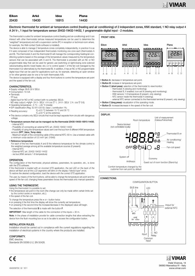
FRONT VIEW.
• Button A: decrease in temperature set-point.• Button B: increase in temperature set-point.• Button C (short press): selection of the thermostat to view/monitor:
- thermostat A (viewing and monitoring);- thermostat B, if enabled; icon ext lit (viewing and monitoring);- KNX sensors 1-8 temperature (if present, only viewing);- NTC sensor inside the thermostat A (viewing);- external NTC sensor connected to the thermostat terminal (if present, only viewing).
• Button C (long press): visualization of the operating mode.• Button D: increase/decrease in the speed of the fan-coil.
ext
DISPLAY.
Room temperatureUnit of measurement (Celsius/Fahrenheit)
Air conditioning/Heating
Fan-coil speed
Guest out of room function (Stand-by)Antifreeze
System off
Comfort temperature changed by the customer from set-point by default
Economy
Device blocked (not controllable locally)
Thermostat B on
The thermostat is suited for ambient temperature control (heating and air-conditioning) and it can interact with other thermostats (whose measured temperatures can be used to determine the “weighted” temperature) and with a supervision centre (PC in reception or technical room where, for example, the Well-contact Suite software is installed). The device is able to manage 2 temperature zones completely independently; in practice it is as if it were composed of two independent thermostats monitoring one zone each (thermostats A and B). The thermostat A and the thermostat B will manage the corresponding heating/air-con-ditioning systems based on the average of the temperature values measured by the temperature sensors that can be associated with A and B. The thermostat is provided with an NC or NO programmable relay that can be used for generic use (switching on light/closing zone solenoid valve/activating electric towel heater, etc.) or to control speed 1 of the fan-coil managed by the thermostat A (or alternatively by the thermostat B). In addition, it has an NC or NO programmable digital input that can be used for applications such as, for example, detecting an open window or for other general uses for one or for both thermostats A/B.The device is equipped with a display and four front buttons to control the temperature set-point and the speed of the fan-coil.
CHARACTERISTICS.• Supply voltage: BUS 29 V SELV.• Consumption: 10 mA• Terminals:- TP bus;- digital input for NO or NC contact (with no potential, SELV);- NO relay output ( 24 V~ SELV 4 A cos 1; 24 V~ SELV 2 A cos 0.6);• Operating temperature: -5 °C - +45 °C (inside)• ErP classification (Reg. EU 811/2013): class I, contribution 1%; ±0.5 °C between 15 °C and 30 °C• Reading accuracy:
±0.8 °C at the extremes• This device contains only SELV circuits that must be kept separate from circuits with dangerous
voltage.
• Temperature sensors that can be managed via the thermostat 20430-19430-16915-14430.- Internal NTC- Possibility of connecting an external NTC art. 20432-19432-14432- Possibility of using the temperature values sent over the bus from 8 different KNX temperature sensors (DPT_Value_Temp data).- Maximum length of the connecting cable of the external NTC: 60 m. Use a twisted cable with a minimum cross-section of 0.5 mm2 (art. 01840)
• Reference temperatureFor each of the two thermostats A and B the reference temperature for the climate control is the weighted average among all the available temperature sources (if present):- Internal NTC- External NTC art. 20432-19432-14432- via bus (KNX sensors 1-8 temperature)
OPERATION.The configuration of the thermostat, physical address, parameters, its operation, etc., is done with the ETS software.If the thermostat is loaded with an incorrect ETS application, the red LED on the back of the device will flash and all the LCD segments will blink on the display (“device type” error).To restore the desired configuration, load the device with the correct ETS application.
The user, by means of the front buttons, will be able to change the temperature set point and the speed of the fan-coil; changing these parameters forces the thermostat onto manual operation.
USING THE THERMOSTAT.Using the thermostat it is possible to set: • the temperature set-point in the room (the change can only be made within certain limits set by the control centre or reception, etc.); • the speed of the fan-coil.
To change the temperature press the + or - button twice:• on pressing it the first time the display will show the currently set temperature;• on pressing it the second time the increase/decrease in the displayed value will begin.
The selection of the thermostat B is made with the button F.
IMPORTANT: Max length of the cable for the connection of the inputs = 30 m.
Note: In the phase of installation provide for cable connection lengths that allow extracting the device from the flush mounting box so as to be able to access the configuration button.
INSTALLATION RULES.Installation should be carried out in compliance with the current regulations regarding the installation of electrical systems in the country where the products are installed.
CONFORMITY.EMC directive.Standards EN 50090-2-2, EN 50428.
CONNECTIONS.
BUS line
Commoninput
Relay C NOInput
LED
CONFIGURATION BUTTON
Imput for external NTC
THERMOSTAT
OFF
A B C D
OFF
A B C D
OFF
A B C D
Eikon
OFF
THERMOSTAT
F
A B C D
Arké Idea Plana
Viale Vicenza, 1436063 Marostica VI - Italy
www.vimar.com49400397D0 02 1611
Eikon
20430Arké
19430Idea
16915Plana
14430
Thermostat électronique pour le contrôle de la température ambiante de 2 zones indépendantes (chauffage et climatisation), standard KNX, 1 sortie à relais NO 4 A 24 V~, 1 entrée pour capteur de température 20432-19432-14432, 1 entrée numérique programmable - 2 modules.
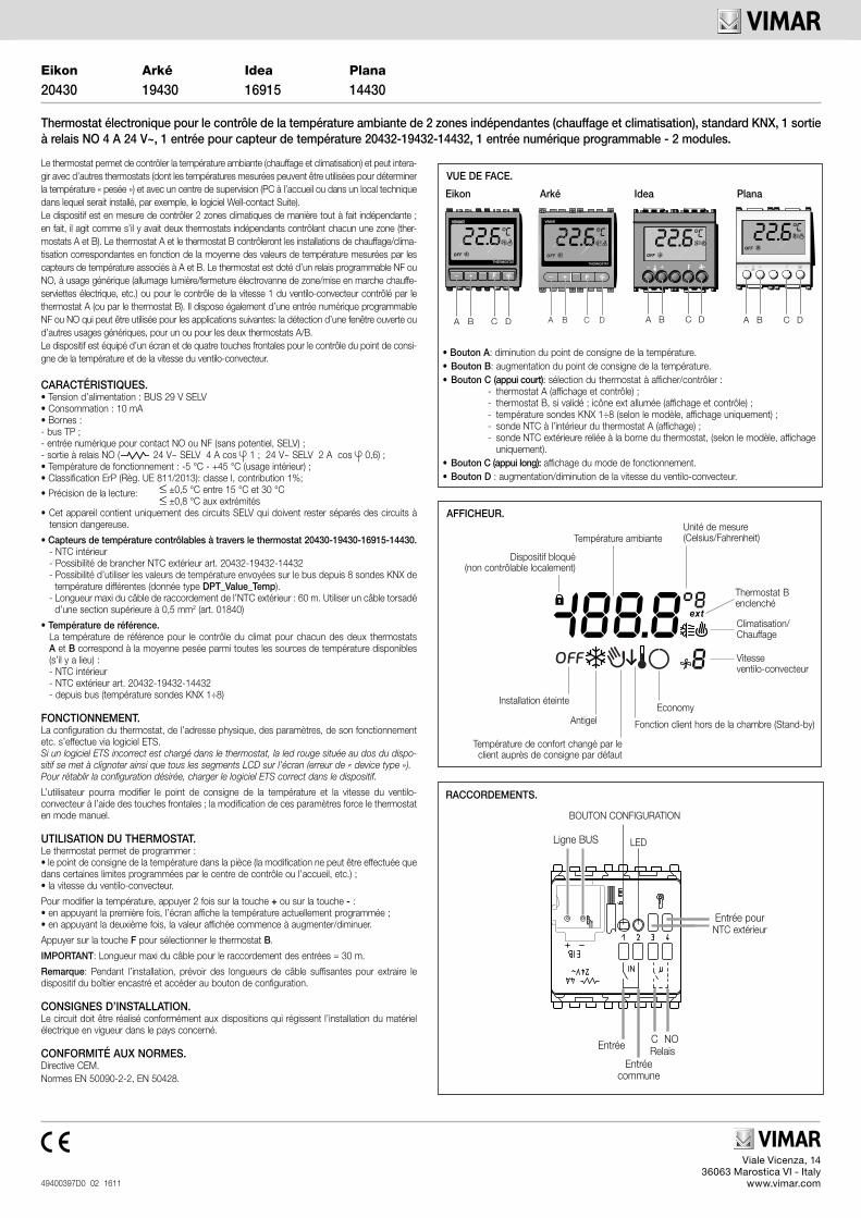
VUE DE FACE.
• Bouton A: diminution du point de consigne de la température.• Bouton B: augmentation du point de consigne de la température.• Bouton C (appui court): sélection du thermostat à afficher/contrôler :
- thermostat A (affichage et contrôle) ;- thermostat B, si validé ; icône ext allumée (affichage et contrôle) ;- température sondes KNX 1÷8 (selon le modèle, affichage uniquement) ;- sonde NTC à l’intérieur du thermostat A (affichage) ;- sonde NTC extérieure reliée à la borne du thermostat, (selon le modèle, affichage
uniquement).• Bouton C (appui long): affichage du mode de fonctionnement.• Bouton D : augmentation/diminution de la vitesse du ventilo-convecteur.
ext
AFFICHEUR.
Température ambianteUnité de mesure (Celsius/Fahrenheit)
Climatisation/Chauffage
Vitesse ventilo-convecteur
Fonction client hors de la chambre (Stand-by)Antigel
Installation éteinte
Température de confort changé par le client auprès de consigne par défaut
Economy
Dispositif bloqué (non contrôlable localement)
Thermostat B enclenché
RACCORDEMENTS.
Ligne BUS
Entrée commune
Relais C NO Entrée
LED
BOUTON CONFIGURATION
Le thermostat permet de contrôler la température ambiante (chauffage et climatisation) et peut intera-gir avec d’autres thermostats (dont les températures mesurées peuvent être utilisées pour déterminer la température « pesée ») et avec un centre de supervision (PC à l’accueil ou dans un local technique dans lequel serait installé, par exemple, le logiciel Well-contact Suite). Le dispositif est en mesure de contrôler 2 zones climatiques de manière tout à fait indépendante ; en fait, il agit comme s’il y avait deux thermostats indépendants contrôlant chacun une zone (ther-mostats A et B). Le thermostat A et le thermostat B contrôleront les installations de chauffage/clima-tisation correspondantes en fonction de la moyenne des valeurs de température mesurées par les capteurs de température associés à A et B. Le thermostat est doté d’un relais programmable NF ou NO, à usage générique (allumage lumière/fermeture électrovanne de zone/mise en marche chauffe-serviettes électrique, etc.) ou pour le contrôle de la vitesse 1 du ventilo-convecteur contrôlé par le thermostat A (ou par le thermostat B). Il dispose également d’une entrée numérique programmable NF ou NO qui peut être utilisée pour les applications suivantes: la détection d’une fenêtre ouverte ou d’autres usages génériques, pour un ou pour les deux thermostats A/B.Le dispositif est équipé d’un écran et de quatre touches frontales pour le contrôle du point de consi-gne de la température et de la vitesse du ventilo-convecteur.
CARACTÉRISTIQUES.• Tension d’alimentation : BUS 29 V SELV• Consommation : 10 mA• Bornes :- bus TP ;- entrée numérique pour contact NO ou NF (sans potentiel, SELV) ;- sortie à relais NO ( 24 V~ SELV 4 A cos 1 ; 24 V~ SELV 2 A cos 0,6) ;• Température de fonctionnement : -5 °C - +45 °C (usage intérieur) ;• Classification ErP (Règ. UE 811/2013): classe I, contribution 1%; ±0,5 °C entre 15 °C et 30 °C• Précision de la lecture:
±0,8 °C aux extrémités• Cet appareil contient uniquement des circuits SELV qui doivent rester séparés des circuits à
tension dangereuse.
• Capteurs de température contrôlables à travers le thermostat 20430-19430-16915-14430.- NTC intérieur- Possibilité de brancher NTC extérieur art. 20432-19432-14432- Possibilité d’utiliser les valeurs de température envoyées sur le bus depuis 8 sondes KNX de température différentes (donnée type DPT_Value_Temp).- Longueur maxi du câble de raccordement de l’NTC extérieur : 60 m. Utiliser un câble torsadé d’une section supérieure à 0,5 mm2 (art. 01840)
• Température de référence.La température de référence pour le contrôle du climat pour chacun des deux thermostats A et B correspond à la moyenne pesée parmi toutes les sources de température disponibles (s’il y a lieu) :- NTC intérieur- NTC extérieur art. 20432-19432-14432- depuis bus (température sondes KNX 1÷8)
FONCTIONNEMENT.La configuration du thermostat, de l’adresse physique, des paramètres, de son fonctionnement etc. s’effectue via logiciel ETS.Si un logiciel ETS incorrect est chargé dans le thermostat, la led rouge située au dos du dispo-sitif se met à clignoter ainsi que tous les segments LCD sur l’écran (erreur de « device type »).Pour rétablir la configuration désirée, charger le logiciel ETS correct dans le dispositif.
L’utilisateur pourra modifier le point de consigne de la température et la vitesse du ventilo-convecteur à l’aide des touches frontales ; la modification de ces paramètres force le thermostaten mode manuel.
UTILISATION DU THERMOSTAT.Le thermostat permet de programmer : • le point de consigne de la température dans la pièce (la modification ne peut être effectuée que dans certaines limites programmées par le centre de contrôle ou l’accueil, etc.) ; • la vitesse du ventilo-convecteur.
Pour modifier la température, appuyer 2 fois sur la touche + ou sur la touche - :• en appuyant la première fois, l’écran affiche la température actuellement programmée ;• en appuyant la deuxième fois, la valeur affichée commence à augmenter/diminuer.
Appuyer sur la touche F pour sélectionner le thermostat B.
IMPORTANT: Longueur maxi du câble pour le raccordement des entrées = 30 m.
Remarque: Pendant l’installation, prévoir des longueurs de câble suffisantes pour extraire le dispositif du boîtier encastré et accéder au bouton de configuration.
CONSIGNES D’INSTALLATION.Le circuit doit être réalisé conformément aux dispositions qui régissent l’installation du matériel électrique en vigueur dans le pays concerné.
CONFORMITÉ AUX NORMES.Directive CEM.Normes EN 50090-2-2, EN 50428.
Entrée pourNTC extérieur
THERMOSTAT
OFF
A B C D
OFF
A B C D
OFF
A B C D
Eikon
OFF
THERMOSTAT
F
A B C D
Arké Idea Plana

Viale Vicenza, 1436063 Marostica VI - Italy
www.vimar.com49400397D0 02 1611
Eikon
20430Arké
19430Idea
16915Plana
14430
Elektronischer Thermostat zur Raumtemperaturregelung in 2 unabhängigen Zonen (Heizung und Klimatisierung), KNX Standard, 1 NO-Relaisausgang 4 A 24 V~, 1 Eingang für Temperaturfühler 20432-19432-14432, 1 programmierbarer Digitaleingang - 2 Module.
FRONTANSICHT.
• Taste A: Temperatursollwert verringern.• Taste B: Temperatursollwert erhöhen.• Taste C (kurz drücken): Wahl des anzuzeigenden/zu regelndenThermostats:
- Thermostat A (Anzeige und Regelung);- Thermostat B, falls aktiviert; Symbol ext leuchtet (Anzeige und Regelung);- Temperatur KNX-Sonden 1÷8 (falls vorhanden, nur Anzeige);- thermostatinterne NTC-Sonde A (Anzeige);- externe NTC-Sonde angeschlossen an die Thermostatklemme, (falls vorhanden,
nur Anzeige).• Taste C (langes drücken): Anzeige des Betriebsmodus.• Taste D: Drehzahl des Fan Coils erhöhen/verringern.
ext
DISPLAY.
RaumtemperaturMaßeinheit (Celsius/Fahrenheit)
Klimatisierung/Heizung
Drehzahl Fan Coil
Funktion Kunde nicht im Zimmer (Standby)Frostschutz
Anlage aus
Comfort Temperatur durch den Kunden vom Sollwert geändert wird standardmäßig
Economy
Gerät gesperrt (nicht lokal steuerbar)
Thermostat B aktiviert
ANSCHLÜSSE.
BUS-Leitung
Gemeinsamer Eingang
Relais C NO Eingang
LED
KONFIGURATIONSTASTE
Der Thermostat eignet sich zur Raumtemperaturregelung (Heizung und Klimatisierung) und kann mit ande-ren Thermostaten (deren gemessene Temperaturwerte zur Bestimmung der “gewichteten” Temperatur verwendbar sind) ebenso interagieren wie mit einem Überwachungszentrum (PC an der Reception oder im technischen Raum, in dem zum Beispiel die Software Well-Contact-Suite installiert ist). Das Gerät ist in der Lage, 2 Klimazonen vollständig unabhängig voneinander zu verwalten, als würde er praktisch aus zwei separaten Thermostaten bestehen, die jeweils eine Zone regeln (Thermostat A und B). Der Thermostat verfügt über ein als NC oder NO programmierbares Relais für allgemeine Verwendungen (Licht einschalten/zonenspezifisches Magnetventil schließen/elektrischen Handtuchwärmer aktivieren usw.) oder für die Kontrolle der Drehzahl 1 des vom Thermostat A (oder alternativ vom Thermostat B) verwalteten Fan Coils . Ausgestattet ist er darüber hinaus mit einem als NC oder NO programmierbaren Digitaleingang, der für Anwendungen wie beispielsweise die Meldung eines geöffneten Fensters oder für andere allgemeine Verwendungen sowohl für einen als auch für beide Thermostate A/Beingesetzt werden kann.Das Gerät ist mit einem Display und vier Tasten an der Vorderseite zur Kontrolle des Temperatursollwerts und der Drehzahl des Fan Coils ausgestattet.
CARATTERISTICHE.• Versorgungsspannung: BUS 29 V SELV• Stromverbrauch: 10 mA• Klemmen:- TP-BUS;- Digitaleingang für Schließer- oder Öffnerkontakt (potentialfrei, SELV);- NO-Relaisausgang ( 24 V~ SELV 4 A cos 1; 24 V~ SELV 2 A cos 0,6);• Betriebstemperatur -5 °C - +45 °C (Innenbereich);• ErP Klassifikation (Verord. EU 811/2013): Klasse I, Beitrag 1%; ±0,5 °C zwischen 15 °C und 30 °C• Genauigkeit der Ablesung:
±0,8 °C bei Extremwerten• Dieses Gerät enthält nur SELV-Stromkreise, die von Stromkreisen mit gefährlicher Spannung
getrennt gehalten werden.
• Vom Thermostat 20430-19430-16915-14430 steuerbare Temperaturfühler.- interner NTC-Fühler- Anschlussmöglichkeit des externen NTC-Fühlers Art. 20432-19432-14432- Verwendungsmöglichkeit der von 8 verschiedenen KNX-Temperatursonden an die Busleitung gesendeten Temperaturwerte (Angabe vom Typ DPT_Value_Temp).- Maximale Kabelanschlusslänge des externen NTC-Fühlers: 60 m. Zu verwenden ist ein ver drilltes Kabel mit 0.5 mm2 Mindestquerschnitt (Art. 01840)
• Bezugstemperatur.Für beide Thermostate A und B ist die für die Klimaregelung maßgebende Bezugstemperatur das gewichtete Mittel aller verfügbaren Temperaturquellen (falls vorhanden):- interner NTC-Fühler- externer NTC-Fühler Art. 20432-19432-14432- von Busleitung (KNX-Temperatursonden 1÷8)
FUNKTIONSWEISE.Die Konfiguration des Thermostats, der physischen Adresse, der Parameter, seines Betriebs usw. erfolgt mithilfe der Software ETS.Wenn im Thermostat eine falsche ETS-Anwendung geladen wird, blinkt die rote LED an der Geräterückseite, und auf dem Display blinken alle LCD-Segmente (Fehler “device type”).Zur Wiederherstellung der gewünschten Konfiguration die korrekte ETS-Anwendung in das Gerät laden.
Über die Tasten an der Vorderseite kann der Anwender den Temperatursollwert und die Drehzahl des Fan Coils ändern; durch die Änderung dieser Parameter wird der Thermostat auf manuellen Betrieb gesetzt.
GEBRAUCH DES THERMOSTATS.Über den Thermostat können folgende Optionen eingestellt werden: • der Raumtemperatursollwert (die Änderung ist nur innerhalb bestimmter, vom Kontrollzentrum bzw. von der Reception usw. vorgegebener Grenzen möglich); • die Drehzahl des Fan Coils.
Zur Temperaturveränderung 2 Mal die Taste + oder -drücken:• beim ersten Tastendruck wird auf dem Display die momentan eingestellte Temperatur angezeigt;• beim zweiten Tastendruck beginnt die Erhöhung/Verringerung des angezeigten Werts.
Der Thermostat B wird über die Taste F gewählt.
WICHTIG: Maximale Kabelanschlusslänge der Eingänge = 30 m.
Hinweis: Während der Installation sind Kabelanschlusslängen vorzusehen, die das Herausnehmen des Geräts aus dem UP-Gehäuse gestatten, um Zugang zur Konfigurationstaste zu haben.
INSTALLATIONSVORSCHRIFTEN.Die Installation hat nach den im Anwendungsland des Produkts geltenden Vorschriften zur Installation elektrischen Materials zu erfolgen.
NORMKONFORMITÄT.EMV-Richtlinie.Normen EN 50090-2-2, EN 50428.
Eingang für externer NTC
THERMOSTAT
OFF
A B C D
OFF
A B C D
OFF
A B C D
Eikon
OFF
THERMOSTAT
F
A B C D
Arké Idea Plana