Effect of Axial Load Redistribution in Progressive...
15
ΕΠΕΣ Ελληνική Επιστημονική Εταιρία Ερευνών Σκυροδέματος (ΕΠΕΣ) – ΤΕΕ / Τμήμα Κεντρικής Μακεδονίας Πανελλήνιο Συνέδριο Σκυροδέματος «Κατασκευές από Σκυρόδεμα» Θεσσαλονίκη, 10-12 Νοεμβρίου 2016 Effect of Axial Load Redistribution in Progressive Collapse of Existing R/C Structures Dimitrios K. Zimos PhD candidate, City, University of London, [email protected] Vassilis K. Papanikolaou Assistant Professor, Aristotle University of Thessaloniki, [email protected] Panagiotis E. Mergos Lecturer, City, University of London, [email protected] Andreas J. Kappos Professor, City, University of London and Aristotle University of Thessaloniki, [email protected], [email protected] Introduction Many existing reinforced concrete structures have been designed according to older, less stringent seismic codes compared to current guidelines or might not have been designed to withstand seismic loads at all. Therefore, they are quite vulnerable to damage from earthquake loading, potentially even leading to collapse of the whole structure or a major part of it. This happens in a progressive manner starting with the failure of one or few elements and propagating through the structure, thus termed progressive collapse (Starossek, 2008). Progressive collapse scenarios are broadly classified into side- sway collapse, which takes place when seismic lateral forces exceed the lateral capacity of the structure, and vertical collapse that pertains to exceeding the structure’s vertical (bearing) capacity (Matsukawa et al., 2012). The former is more common in ductile frames, while non-ductile R/C frames usually undergo the latter mode of collapse, their elements losing their vertical capacity before excessive lateral displacements can be reached (Adam & Ibarra, 2014). Loss of axial load capacity of vertical R/C elements has been shown through post-earthquake reconnaissance to be one of the most common reasons of vertical progressive collapse of older R/C frame buildings (Ghannoum et al., 2008). Such axial failure of a column can occur after its shear failure, subsequently, or even prior, to yielding of its longitudinal reinforcement, through disintegration of the poorly confined concrete core of a vertical element with continuous lateral cycling (Sezen & Moehle, 2006). The vertical loads previously carried by a failing member are subsequently redistributed to neighbouring vertical elements. Therefore, the ability of a framing system to resist progressive collapse in such a ‘scenario’ hinges on both the ability of horizontal elements to transfer the loads being redistributed to adjacent vertical elements and the latter's ability to resist them without considerably losing their strength and deformability (Lodhi, 2012). Existing research work has looked extensively into the adjacent horizontal elements' capacity to redistribute the vertical loads, neglecting the neighbouring columns or assuming they are capable of bearing the extra vertical load. Several analytical studies, experimental programmes and field studies have highlighted that the R/C beams and slabs adjacent to a failing column redistribute the load initially via beam (or Vierendeel) action, followed by compressive arch action, as the vertical displacement increases, eventually turning into catenary action with the whole depth being in tension
-
Upload
nguyendieu -
Category
Documents
-
view
228 -
download
3
Transcript of Effect of Axial Load Redistribution in Progressive...
ΕΠΕΣ Ελληνική Επιστημονική Εταιρία Ερευνών Σκυροδέματος (ΕΠΕΣ) – ΤΕΕ / Τμήμα Κεντρικής Μακεδονίας
Πανελλήνιο Συνέδριο Σκυροδέματος «Κατασκευές από Σκυρόδεμα»
Θεσσαλονίκη, 10-12 Νοεμβρίου 2016
Effect of Axial Load Redistribution in Progressive Collapse of Existing R/C
Structures
Dimitrios K. Zimos
PhD candidate, City, University of London, [email protected]
Vassilis K. Papanikolaou
Assistant Professor, Aristotle University of Thessaloniki, [email protected]
Panagiotis E. Mergos
Lecturer, City, University of London, [email protected]
Andreas J. Kappos
Professor, City, University of London and Aristotle University of Thessaloniki,
[email protected], [email protected]
Introduction
Many existing reinforced concrete structures have been designed according to older, less stringent
seismic codes compared to current guidelines or might not have been designed to withstand seismic
loads at all. Therefore, they are quite vulnerable to damage from earthquake loading, potentially even
leading to collapse of the whole structure or a major part of it. This happens in a progressive manner
starting with the failure of one or few elements and propagating through the structure, thus termed
progressive collapse (Starossek, 2008). Progressive collapse scenarios are broadly classified into side-
sway collapse, which takes place when seismic lateral forces exceed the lateral capacity of the
structure, and vertical collapse that pertains to exceeding the structure’s vertical (bearing) capacity
(Matsukawa et al., 2012). The former is more common in ductile frames, while non-ductile R/C
frames usually undergo the latter mode of collapse, their elements losing their vertical capacity before
excessive lateral displacements can be reached (Adam & Ibarra, 2014).
Loss of axial load capacity of vertical R/C elements has been shown through post-earthquake
reconnaissance to be one of the most common reasons of vertical progressive collapse of older R/C
frame buildings (Ghannoum et al., 2008). Such axial failure of a column can occur after its shear
failure, subsequently, or even prior, to yielding of its longitudinal reinforcement, through
disintegration of the poorly confined concrete core of a vertical element with continuous lateral
cycling (Sezen & Moehle, 2006). The vertical loads previously carried by a failing member are
subsequently redistributed to neighbouring vertical elements. Therefore, the ability of a framing
system to resist progressive collapse in such a ‘scenario’ hinges on both the ability of horizontal
elements to transfer the loads being redistributed to adjacent vertical elements and the latter's ability to
resist them without considerably losing their strength and deformability (Lodhi, 2012).
Existing research work has looked extensively into the adjacent horizontal elements' capacity to
redistribute the vertical loads, neglecting the neighbouring columns or assuming they are capable of
bearing the extra vertical load. Several analytical studies, experimental programmes and field studies
have highlighted that the R/C beams and slabs adjacent to a failing column redistribute the load
initially via beam (or Vierendeel) action, followed by compressive arch action, as the vertical
displacement increases, eventually turning into catenary action with the whole depth being in tension
ΕΠΕΣ Ελληνική Επιστημονική Εταιρία Ερευνών Σκυροδέματος (ΕΠΕΣ) – ΤΕΕ / Τμήμα Κεντρικής Μακεδονίας
Πανελλήνιο Συνέδριο Σκυροδέματος «Κατασκευές από Σκυρόδεμα»
Θεσσαλονίκη, 10-12 Νοεμβρίου 2016
(Sasani et al., 2007; Sasani & Sagiroglu, 2008; He & Yin, 2008; Izzuddin et al., 2008; Vlassis et al.,
2008; Yi et al., 2008; Sasani & Sagiroglu, 2010; Li et al., 2011; Choi & Kim, 2011; Jahromi et al.,
2012; Yu & Tan, 2013; Lew et al., 2014; Li et al., 2014; Palmisano, 2014). The General Services
Administration guidelines (GSA, 2013) also focus on load redistribution systems of the gravity loads
to neighbouring vertical load-bearing elements without consideration of the latter.
However, previous research has not concentrated adequately on the neighbouring vertical elements of
an axially failing column. An abrupt dynamic increase of the axial load of these elements takes place
and they ought to be checked in order to achieve an accurate assessment of the ability of the structure
to arrest progressive collapse (Xu & Ellingwood, 2011). Xu & Ellingwood (2011) accounted for this
via considering the potential buckling of neighbouring vertical elements in a design procedure against
progressive collapse of steel buildings, but there is no study of older R/C buildings having accounted
for this effect. Naturally, it could be readily taken into account in distributed inelasticity or fibre
elements, due to the axial-flexure interaction, so they can be used in cases of flexure-critical elements.
However, this is not the case for shear- or flexure-shear-critical elements modelled through beam-
column models explicitly accounting for shear deformations, where this phenomenon has not yet been
reportedly modelled.
Another common assumption in progressive collapse assessment is that of undamaged vertical
elements; this might be appropriate for blast-induced or similar collapse scenarios, where damage can
be largely assumed localised in a single structural element or a small set of elements. Nevertheless,
earthquake-induced collapse scenarios pose a further difficulty in that there is global damage in a large
part of, if not the entire, building even before the loss of a column's vertical load-bearing capacity.
Therefore, the damage state of a column neighbouring an axially failed vertical member has to be
appropriately taken into account in a realistic earthquake-induced progressive collapse assessment,
particularly so since the increase in the axial loading exacerbates the post-peak response of the
damaged column.
Previous experimental studies looking into the non-linear, and especially post-peak, lateral response of
substandard R/C columns have looked extensively at the response under constant vertical load (e.g.
Lynn et al., 1996; Yoshimura & Yamanaka, 2000; Yoshimura & Nakamura, 2002; Nakamura &
Yoshimura, 2002; Ousalem et al., 2003; Yoshimura et al., 2004; Matamoros & Woods; 2010) as well
as variable axial load corresponding to a corner column case, i.e. axial load proportional to the lateral
force acting on the column (e.g. Ramirez & Jirsa, 1980; Ousalem et al., 2002; Sezen & Moehle, 2006).
Recently, Nakamura & Yoshimura (2014) also investigated the effect that decreasing axial load has on
the lateral non-linear response of substandard columns, thus simulating the response of a column that
starts failing axially and its axial load starts decreasing correspondingly due to vertical load
redistribution. Nonetheless, to the authors’ best knowledge, the effect of the vertical load redistribution
on the neighbouring R/C columns has not been investigated at all, thus far.
The main objective of this study is the description of the design of an experimental programme with
the aim to shed further light on this phenomenon, i.e. the effect of vertical load redistribution on the
non-linear response of shear- and flexure-shear-critical R/C columns neighbouring failing vertical
members. Analyses are conducted with existing Finite Element Analysis models in order to
supplement the experimental design, results of which are presented in this study.
ΕΠΕΣ Ελληνική Επιστημονική Εταιρία Ερευνών Σκυροδέματος (ΕΠΕΣ) – ΤΕΕ / Τμήμα Κεντρικής Μακεδονίας
Πανελλήνιο Συνέδριο Σκυροδέματος «Κατασκευές από Σκυρόδεμα»
Θεσσαλονίκη, 10-12 Νοεμβρίου 2016
Experimental design
Conceptual design
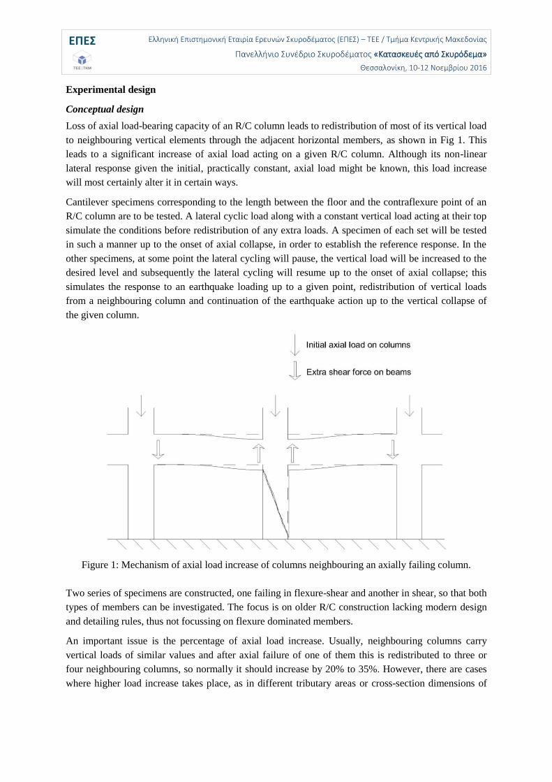
Loss of axial load-bearing capacity of an R/C column leads to redistribution of most of its vertical load
to neighbouring vertical elements through the adjacent horizontal members, as shown in Fig 1. This
leads to a significant increase of axial load acting on a given R/C column. Although its non-linear
lateral response given the initial, practically constant, axial load might be known, this load increase
will most certainly alter it in certain ways.
Cantilever specimens corresponding to the length between the floor and the contraflexure point of an
R/C column are to be tested. A lateral cyclic load along with a constant vertical load acting at their top
simulate the conditions before redistribution of any extra loads. A specimen of each set will be tested
in such a manner up to the onset of axial collapse, in order to establish the reference response. In the
other specimens, at some point the lateral cycling will pause, the vertical load will be increased to the
desired level and subsequently the lateral cycling will resume up to the onset of axial collapse; this
simulates the response to an earthquake loading up to a given point, redistribution of vertical loads
from a neighbouring column and continuation of the earthquake action up to the vertical collapse of
the given column.
Figure 1: Mechanism of axial load increase of columns neighbouring an axially failing column.
Two series of specimens are constructed, one failing in flexure-shear and another in shear, so that both
types of members can be investigated. The focus is on older R/C construction lacking modern design
and detailing rules, thus not focussing on flexure dominated members.
An important issue is the percentage of axial load increase. Usually, neighbouring columns carry
vertical loads of similar values and after axial failure of one of them this is redistributed to three or
four neighbouring columns, so normally it should increase by 20% to 35%. However, there are cases
where higher load increase takes place, as in different tributary areas or cross-section dimensions of
ΕΠΕΣ Ελληνική Επιστημονική Εταιρία Ερευνών Σκυροδέματος (ΕΠΕΣ) – ΤΕΕ / Τμήμα Κεντρικής Μακεδονίας
Πανελλήνιο Συνέδριο Σκυροδέματος «Κατασκευές από Σκυρόδεμα»
Θεσσαλονίκη, 10-12 Νοεμβρίου 2016
neighbouring columns. Additionally, a higher increase will lead to a more pronounced effect on the
lateral response. Therefore, a 50% increase in the axial load is chosen herein.
Another important issue is the damage state at the onset of vertical load increase along the response
history of the column; as mentioned previously, in earthquake-induced collapse scenarios there is
substantial damage in most of the building before the loss of a column's vertical load-bearing capacity
and the difference in the damage state considered might have a significant impact on the resulting
response. For instance, an axial load increase in the early stages of pre-peak response might be
beneficial for the overall response of the member, while the same increase in the post-peak stage can
prove fatal. As the main focus of this study is mainly on the peak and post-peak response of flexure-
shear and shear critical R/C columns, two different points of axial load increase were selected in order
to observe the response difference, i.e. one cycle before and one cycle after the onset of shear failure.
Test specimens
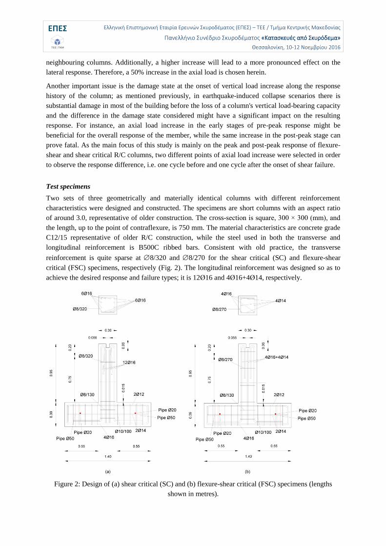
Two sets of three geometrically and materially identical columns with different reinforcement
characteristics were designed and constructed. The specimens are short columns with an aspect ratio
of around 3.0, representative of older construction. The cross-section is square, 300 × 300 (mm), and
the length, up to the point of contraflexure, is 750 mm. The material characteristics are concrete grade
C12/15 representative of older R/C construction, while the steel used in both the transverse and
longitudinal reinforcement is B500C ribbed bars. Consistent with old practice, the transverse
reinforcement is quite sparse at 8/320 and 8/270 for the shear critical (SC) and flexure-shear
critical (FSC) specimens, respectively (Fig. 2). The longitudinal reinforcement was designed so as to
achieve the desired response and failure types; it is 12Ø16 and 4Ø16+4Ø14, respectively.
Figure 2: Design of (a) shear critical (SC) and (b) flexure-shear critical (FSC) specimens (lengths
shown in metres).
ΕΠΕΣ Ελληνική Επιστημονική Εταιρία Ερευνών Σκυροδέματος (ΕΠΕΣ) – ΤΕΕ / Τμήμα Κεντρικής Μακεδονίας
Πανελλήνιο Συνέδριο Σκυροδέματος «Κατασκευές από Σκυρόδεμα»
Θεσσαλονίκη, 10-12 Νοεμβρίου 2016
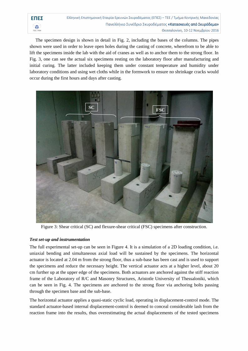
The specimen design is shown in detail in Fig. 2, including the bases of the columns. The pipes
shown were used in order to leave open holes during the casting of concrete, wherefrom to be able to
lift the specimens inside the lab with the aid of cranes as well as to anchor them to the strong floor. In
Fig. 3, one can see the actual six specimens resting on the laboratory floor after manufacturing and
initial curing. The latter included keeping them under constant temperature and humidity under
laboratory conditions and using wet cloths while in the formwork to ensure no shrinkage cracks would
occur during the first hours and days after casting.
Figure 3: Shear critical (SC) and flexure-shear critical (FSC) specimens after construction.
Test set-up and instrumentation
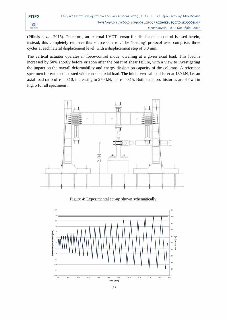
The full experimental set-up can be seen in Figure 4. It is a simulation of a 2D loading condition, i.e.
uniaxial bending and simultaneous axial load will be sustained by the specimens. The horizontal
actuator is located at 2.04 m from the strong floor, thus a sub-base has been cast and is used to support
the specimens and reduce the necessary height. The vertical actuator acts at a higher level, about 20
cm further up at the upper edge of the specimens. Both actuators are anchored against the stiff reaction
frame of the Laboratory of R/C and Masonry Structures, Aristotle University of Thessaloniki, which
can be seen in Fig. 4. The specimens are anchored to the strong floor via anchoring bolts passing
through the specimen base and the sub-base.
The horizontal actuator applies a quasi-static cyclic load, operating in displacement-control mode. The
standard actuator-based internal displacement-control is deemed to conceal considerable lash from the
reaction frame into the results, thus overestimating the actual displacements of the tested specimens
SC FSC
ΕΠΕΣ Ελληνική Επιστημονική Εταιρία Ερευνών Σκυροδέματος (ΕΠΕΣ) – ΤΕΕ / Τμήμα Κεντρικής Μακεδονίας
Πανελλήνιο Συνέδριο Σκυροδέματος «Κατασκευές από Σκυρόδεμα»
Θεσσαλονίκη, 10-12 Νοεμβρίου 2016
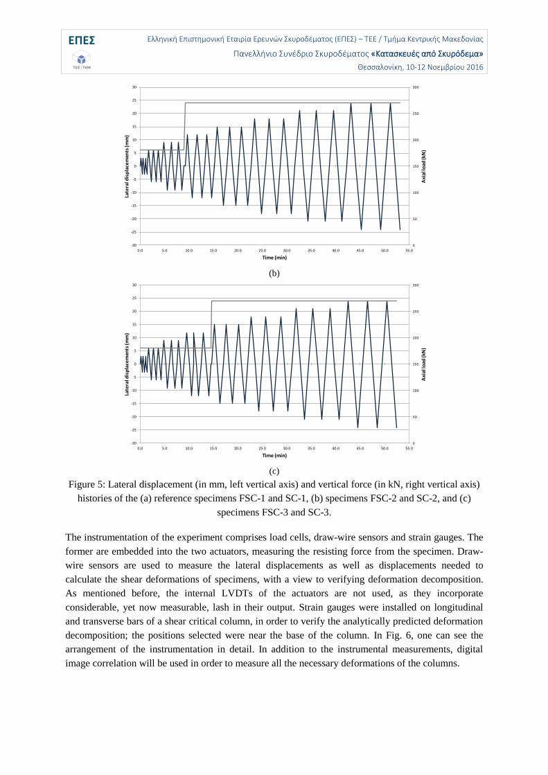
(Pilitsis et al., 2015). Therefore, an external LVDT sensor for displacement control is used herein,
instead; this completely removes this source of error. The ‘loading’ protocol used comprises three
cycles at each lateral displacement level, with a displacement step of 3.0 mm.
The vertical actuator operates in force-control mode, dwelling at a given axial load. This load is
increased by 50% shortly before or soon after the onset of shear failure, with a view to investigating
the impact on the overall deformability and energy dissipation capacity of the columns. A reference
specimen for each set is tested with constant axial load. The initial vertical load is set at 180 kN, i.e. an
axial load ratio of ν = 0.10, increasing to 270 kN, i.e. ν = 0.15. Both actuators' histories are shown in
Fig. 5 for all specimens.
Figure 4: Experimental set-up shown schematically.
(a)
0
20
40
60
80
100
120
140
160
180
200
-30
-25
-20
-15
-10
-5
0
5
10
15
20
25
30
0.0 5.0 10.0 15.0 20.0 25.0 30.0 35.0 40.0 45.0 50.0 55.0
Axi
al lo
ad (k
N)
Late
ral d
isp
lace
men
ts (
mm
)
Time (min)
ΕΠΕΣ Ελληνική Επιστημονική Εταιρία Ερευνών Σκυροδέματος (ΕΠΕΣ) – ΤΕΕ / Τμήμα Κεντρικής Μακεδονίας
Πανελλήνιο Συνέδριο Σκυροδέματος «Κατασκευές από Σκυρόδεμα»
Θεσσαλονίκη, 10-12 Νοεμβρίου 2016
(b)
(c)
Figure 5: Lateral displacement (in mm, left vertical axis) and vertical force (in kN, right vertical axis)
histories of the (a) reference specimens FSC-1 and SC-1, (b) specimens FSC-2 and SC-2, and (c)
specimens FSC-3 and SC-3.
The instrumentation of the experiment comprises load cells, draw-wire sensors and strain gauges. The
former are embedded into the two actuators, measuring the resisting force from the specimen. Draw-
wire sensors are used to measure the lateral displacements as well as displacements needed to
calculate the shear deformations of specimens, with a view to verifying deformation decomposition.
As mentioned before, the internal LVDTs of the actuators are not used, as they incorporate
considerable, yet now measurable, lash in their output. Strain gauges were installed on longitudinal
and transverse bars of a shear critical column, in order to verify the analytically predicted deformation
decomposition; the positions selected were near the base of the column. In Fig. 6, one can see the
arrangement of the instrumentation in detail. In addition to the instrumental measurements, digital
image correlation will be used in order to measure all the necessary deformations of the columns.
0
50
100
150
200
250
300
-30
-25
-20
-15
-10
-5
0
5
10
15
20
25
30
0.0 5.0 10.0 15.0 20.0 25.0 30.0 35.0 40.0 45.0 50.0 55.0
Axi
al lo
ad (k
N)
Late
ral d
isp
lace
men
ts (
mm
)
Time (min)
0
50
100
150
200
250
300
-30
-25
-20
-15
-10
-5
0
5
10
15
20
25
30
0.0 5.0 10.0 15.0 20.0 25.0 30.0 35.0 40.0 45.0 50.0 55.0
Axi
al lo
ad (k
N)
Late
ral d
isp
lace
men
ts (
mm
)
Time (min)
ΕΠΕΣ Ελληνική Επιστημονική Εταιρία Ερευνών Σκυροδέματος (ΕΠΕΣ) – ΤΕΕ / Τμήμα Κεντρικής Μακεδονίας
Πανελλήνιο Συνέδριο Σκυροδέματος «Κατασκευές από Σκυρόδεμα»
Θεσσαλονίκη, 10-12 Νοεμβρίου 2016
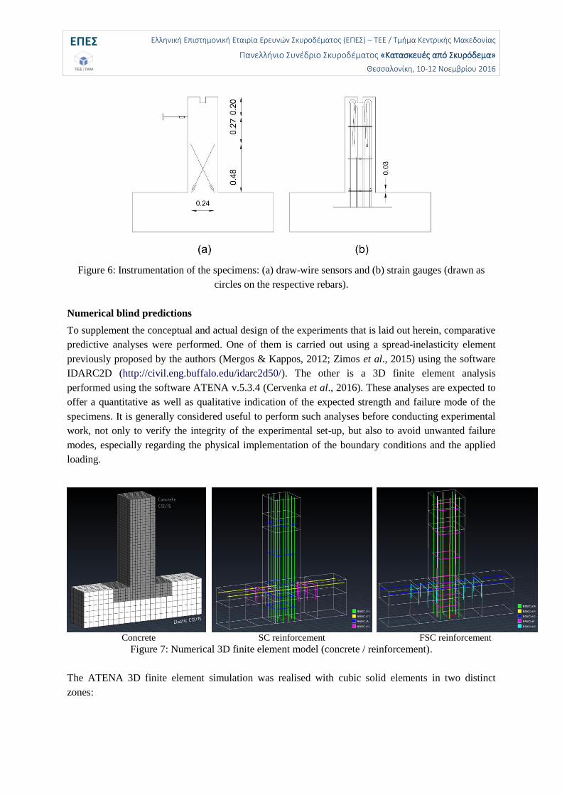
Figure 6: Instrumentation of the specimens: (a) draw-wire sensors and (b) strain gauges (drawn as
circles on the respective rebars).
Numerical blind predictions
To supplement the conceptual and actual design of the experiments that is laid out herein, comparative
predictive analyses were performed. One of them is carried out using a spread-inelasticity element
previously proposed by the authors (Mergos & Kappos, 2012; Zimos et al., 2015) using the software
IDARC2D (http://civil.eng.buffalo.edu/idarc2d50/). The other is a 3D finite element analysis
performed using the software ATENA v.5.3.4 (Cervenka et al., 2016). These analyses are expected to
offer a quantitative as well as qualitative indication of the expected strength and failure mode of the
specimens. It is generally considered useful to perform such analyses before conducting experimental
work, not only to verify the integrity of the experimental set-up, but also to avoid unwanted failure
modes, especially regarding the physical implementation of the boundary conditions and the applied
loading.
Concrete
SC reinforcement
FSC reinforcement
Figure 7: Numerical 3D finite element model (concrete / reinforcement).
The ATENA 3D finite element simulation was realised with cubic solid elements in two distinct
zones:
ΕΠΕΣ Ελληνική Επιστημονική Εταιρία Ερευνών Σκυροδέματος (ΕΠΕΣ) – ΤΕΕ / Τμήμα Κεντρικής Μακεδονίας
Πανελλήνιο Συνέδριο Σκυροδέματος «Κατασκευές από Σκυρόδεμα»
Θεσσαλονίκη, 10-12 Νοεμβρίου 2016
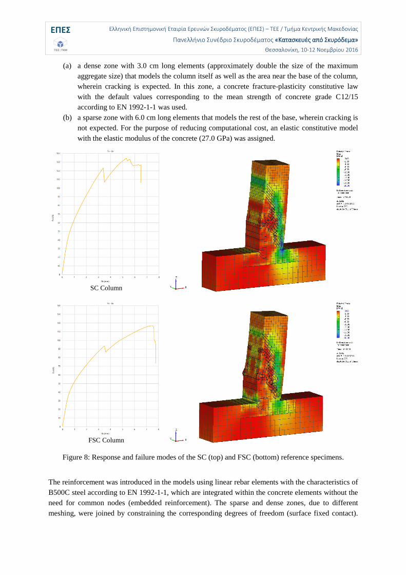
(a) a dense zone with 3.0 cm long elements (approximately double the size of the maximum
aggregate size) that models the column itself as well as the area near the base of the column,
wherein cracking is expected. In this zone, a concrete fracture-plasticity constitutive law
with the default values corresponding to the mean strength of concrete grade C12/15
according to EN 1992-1-1 was used.
(b) a sparse zone with 6.0 cm long elements that models the rest of the base, wherein cracking is
not expected. For the purpose of reducing computational cost, an elastic constitutive model
with the elastic modulus of the concrete (27.0 GPa) was assigned.
SC Column
FSC Column
Figure 8: Response and failure modes of the SC (top) and FSC (bottom) reference specimens.
The reinforcement was introduced in the models using linear rebar elements with the characteristics of
B500C steel according to EN 1992-1-1, which are integrated within the concrete elements without the
need for common nodes (embedded reinforcement). The sparse and dense zones, due to different
meshing, were joined by constraining the corresponding degrees of freedom (surface fixed contact).
ΕΠΕΣ Ελληνική Επιστημονική Εταιρία Ερευνών Σκυροδέματος (ΕΠΕΣ) – ΤΕΕ / Τμήμα Κεντρικής Μακεδονίας
Πανελλήνιο Συνέδριο Σκυροδέματος «Κατασκευές από Σκυρόδεμα»
Θεσσαλονίκη, 10-12 Νοεμβρίου 2016
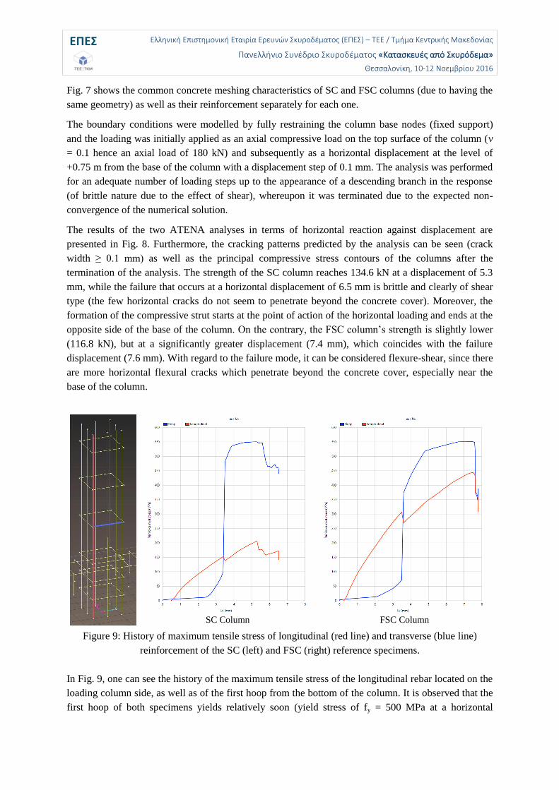
Fig. 7 shows the common concrete meshing characteristics of SC and FSC columns (due to having the
same geometry) as well as their reinforcement separately for each one.
The boundary conditions were modelled by fully restraining the column base nodes (fixed support)
and the loading was initially applied as an axial compressive load on the top surface of the column (ν
= 0.1 hence an axial load of 180 kN) and subsequently as a horizontal displacement at the level of
+0.75 m from the base of the column with a displacement step of 0.1 mm. The analysis was performed
for an adequate number of loading steps up to the appearance of a descending branch in the response
(of brittle nature due to the effect of shear), whereupon it was terminated due to the expected non-
convergence of the numerical solution.
The results of the two ATENA analyses in terms of horizontal reaction against displacement are
presented in Fig. 8. Furthermore, the cracking patterns predicted by the analysis can be seen (crack
width ≥ 0.1 mm) as well as the principal compressive stress contours of the columns after the
termination of the analysis. The strength of the SC column reaches 134.6 kN at a displacement of 5.3
mm, while the failure that occurs at a horizontal displacement of 6.5 mm is brittle and clearly of shear
type (the few horizontal cracks do not seem to penetrate beyond the concrete cover). Moreover, the
formation of the compressive strut starts at the point of action of the horizontal loading and ends at the
opposite side of the base of the column. On the contrary, the FSC column’s strength is slightly lower
(116.8 kN), but at a significantly greater displacement (7.4 mm), which coincides with the failure
displacement (7.6 mm). With regard to the failure mode, it can be considered flexure-shear, since there
are more horizontal flexural cracks which penetrate beyond the concrete cover, especially near the
base of the column.
SC Column
FSC Column
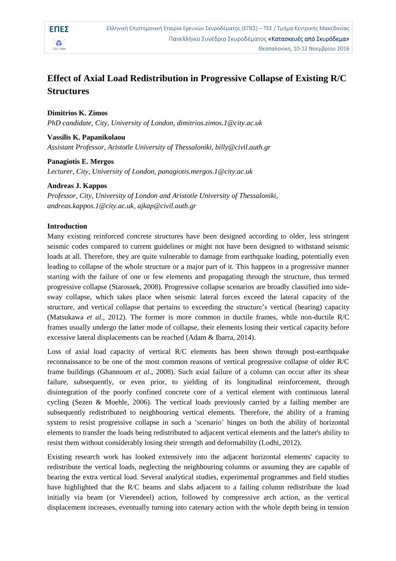
Figure 9: History of maximum tensile stress of longitudinal (red line) and transverse (blue line)
reinforcement of the SC (left) and FSC (right) reference specimens.
In Fig. 9, one can see the history of the maximum tensile stress of the longitudinal rebar located on the
loading column side, as well as of the first hoop from the bottom of the column. It is observed that the
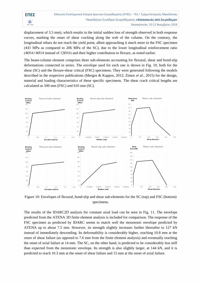
first hoop of both specimens yields relatively soon (yield stress of fy = 500 MPa at a horizontal
ΕΠΕΣ Ελληνική Επιστημονική Εταιρία Ερευνών Σκυροδέματος (ΕΠΕΣ) – ΤΕΕ / Τμήμα Κεντρικής Μακεδονίας
Πανελλήνιο Συνέδριο Σκυροδέματος «Κατασκευές από Σκυρόδεμα»
Θεσσαλονίκη, 10-12 Νοεμβρίου 2016
displacement of 3.5 mm), which results in the initial sudden loss of strength observed in both response
curves, marking the onset of shear cracking along the web of the column. On the contrary, the
longitudinal rebars do not reach the yield point, albeit approaching it much more in the FSC specimen
(443 ΜPa as compared to 206 MPa of the SC), due to the lower longitudinal reinforcement ratio
(4Ø16+4Ø14 instead of 12Ø16) and their higher contribution to flexure, as noted earlier.
The beam-column element comprises three sub-elements accounting for flexural, shear and bond-slip
deformations connected in series. The envelope used for each one is shown in Fig. 10, both for the
shear (SC) and the flexure-shear critical (FSC) specimens. They were generated following the models
described in the respective publications (Mergos & Kappos, 2012; Zimos et al., 2015) for the design,
material and loading characteristics of these specific specimens. The shear crack critical lengths are
calculated as 500 mm (FSC) and 610 mm (SC).
Figure 10: Envelopes of flexural, bond-slip and shear sub-elements for the SC (top) and FSC (bottom)
specimens.
The results of the IDARC2D analysis for constant axial load can be seen in Fig. 11. The envelope
predicted from the ATENA 3D finite element analysis is included for comparison. The response of the
FSC specimen as predicted by IDARC seems to match well the monotonic envelope predicted by
ATENA up to about 7.5 mm. However, its strength slightly increases further thereafter to 127 kN
instead of immediately descending. Its deformability is considerably higher, reaching 10.8 mm at the
onset of shear failure (as opposed to 7.6 mm from the finite element analysis) and eventually reaching
the onset of axial failure at 14 mm. The SC, on the other hand, is predicted to be considerably less stiff
than expected from the monotonic envelope. Its strength is also slightly larger, at 144 kN, and it is
predicted to reach 10.3 mm at the onset of shear failure and 15 mm at the onset of axial failure.
0
20
40
60
80
100
120
140
0 0.05 0.1 0.15 0.2 0.25
Bending moment
(kNm)
Curvature (rad/m)
Flexural sub-element
0
20
40
60
80
100
120
140
0 0.000005 0.00001 0.000015 0.00002 0.000025
Bending moment
(kNm)
Rotation (rad)
Bond-slip sub-element
0
20
40
60
80
100
120
140
160
180
0 0.01 0.02 0.03 0.04 0.05
Shear force (kN)
Shear distortion
Shear sub-element
0
20
40
60
80
100
120
140
0 0.05 0.1 0.15 0.2 0.25
Bending moment
(kNm)
Curvature (rad/m)
Flexural sub-element
0
20
40
60
80
100
120
140
0 0.000005 0.00001 0.000015 0.00002 0.000025
Bending moment
(kNm)
Rotation (rad)
Bond-slip sub-element
0
20
40
60
80
100
120
140
160
180
0 0.01 0.02 0.03 0.04 0.05
Shear force (kN)
Shear distortion
Shear sub-element
ΕΠΕΣ Ελληνική Επιστημονική Εταιρία Ερευνών Σκυροδέματος (ΕΠΕΣ) – ΤΕΕ / Τμήμα Κεντρικής Μακεδονίας
Πανελλήνιο Συνέδριο Σκυροδέματος «Κατασκευές από Σκυρόδεμα»
Θεσσαλονίκη, 10-12 Νοεμβρίου 2016
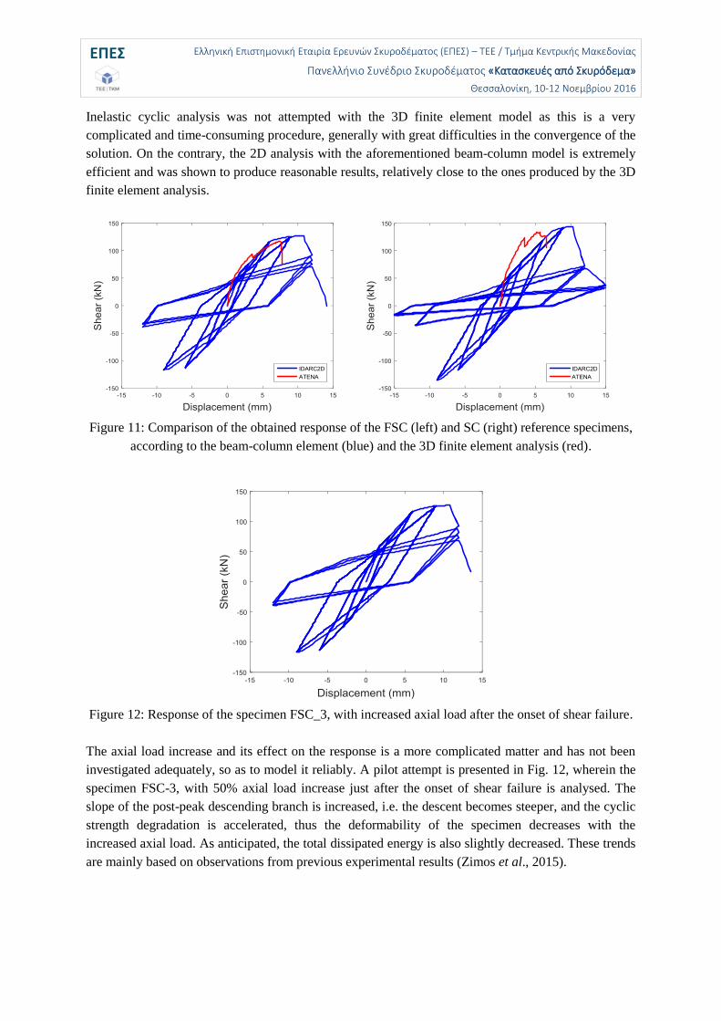
Inelastic cyclic analysis was not attempted with the 3D finite element model as this is a very
complicated and time-consuming procedure, generally with great difficulties in the convergence of the
solution. On the contrary, the 2D analysis with the aforementioned beam-column model is extremely
efficient and was shown to produce reasonable results, relatively close to the ones produced by the 3D
finite element analysis.
Figure 11: Comparison of the obtained response of the FSC (left) and SC (right) reference specimens,
according to the beam-column element (blue) and the 3D finite element analysis (red).
Figure 12: Response of the specimen FSC_3, with increased axial load after the onset of shear failure.
The axial load increase and its effect on the response is a more complicated matter and has not been
investigated adequately, so as to model it reliably. A pilot attempt is presented in Fig. 12, wherein the
specimen FSC-3, with 50% axial load increase just after the onset of shear failure is analysed. The
slope of the post-peak descending branch is increased, i.e. the descent becomes steeper, and the cyclic
strength degradation is accelerated, thus the deformability of the specimen decreases with the
increased axial load. As anticipated, the total dissipated energy is also slightly decreased. These trends
are mainly based on observations from previous experimental results (Zimos et al., 2015).
ΕΠΕΣ Ελληνική Επιστημονική Εταιρία Ερευνών Σκυροδέματος (ΕΠΕΣ) – ΤΕΕ / Τμήμα Κεντρικής Μακεδονίας
Πανελλήνιο Συνέδριο Σκυροδέματος «Κατασκευές από Σκυρόδεμα»
Θεσσαλονίκη, 10-12 Νοεμβρίου 2016
Conclusions
The design of an experimental programme has been presented herein with a view to studying the effect
of vertical load redistribution on the non-linear response of shear-critical and flexure-shear-critical
R/C columns neighbouring failing vertical members. This phenomenon has never been studied
experimentally nor analytically before, so the results are expected to provide useful insight in
modelling this type of behaviour and ultimately contribute to modelling progressive collapse of R/C
buildings more accurately and reliably.
Preliminary analyses predicting the expected response were carried out to offer a quantitative as well
as qualitative indication of the expected strength, deformability and failure mode of the specimens. It
is generally considered useful to perform such analyses before conducting experimental work, in order
to verify the adequacy of the experimental set-up and to avoid unwanted failure modes, especially
regarding the physical realisation of the boundary conditions and the applied loading.
Reasonable agreement is observed using two substantially different modelling approaches, a 2D
analysis using a member-type spread inelasticity element and a 3D finite element analysis using a
plasticity model for concrete. Inelastic cyclic analysis was not attempted with the latter as this is a very
complex and time-consuming procedure, with great difficulties in the convergence of the solution,
contrary to the efficient analysis performed using the former.
The increase of the axial load after the onset of shear failure is expected to decrease the deformability
as well as the total dissipated energy of the specimens. The exact effect will be known once the
experimental results are available.
References
Adam, C. and Ibarra, L.F. (2014), “Seismic Collapse Assessment”, Encyclopedia of Earthquake Engineering, p. 25.
Cervenka, V., Jendele, L. and Cervenka, J. (2016), “ATENA Program Documentation, Part 1: Theory”, Praha, Czech Republic.
GSA (General Services Administration) (2013), “Alternate Path Analysis & Design Guidelines for Progressive Collapse Resistance”, p.143.
Ghannoum, W.M., Moehle, J.P. and Bozorgnia, Y. (2008), “Analytical Collapse Study of Lightly Confined Reinforced Concrete Frames Subjected to Northridge Earthquake Ground Motions”, Journal of Earthquake Engineering, Vol. 12, No. 7, pp.1105–1119.
He, Q. and Yi, W. (2008), “Experimental Study on Collapse-Resistant Behavior of RC Beam-Column Sub-structure considering Catenary Action”, The 14 World Conference on Earthquake Engineering, Beijing, p. 6.
Izzuddin, B.A., Vlassis, A.G., Elghazouli, A.Y. and Nethercot, D.A. (2008), “Progressive collapse of multi-storey buildings due to sudden column loss - Part I: Simplified assessment framework”, Engineering Structures, Vol. 30, No. 5, pp.1308–1318.
Jahromi, H.Z., Izzuddin, A.B., Nethercot, A.D., Donahue, S., Hadjioannou, M., Williamson, E.B., Engelhardt, M., Stevens, D., Marchand, K. and Waggoner, M. (2012), “Robustness Assessment of Building Structures under Explosion”, Buildings, Vol. 2, pp.497–518.
Kim, J. and Choi, H. (2011), “Progressive collapse-resisting capacity of RC beam–column sub-assemblage”, Magazine of Concrete Research, Vol. 63, No. 4, pp.297–310.
Lew, H.S., Bao, Y., Pujol, S. and Sozen, M.A. (2014), “Experimental study of reinforced concrete assemblies under column removal scenario”, ACI Structural Journal, Vol. 111, No. 4, pp.881–892.
ΕΠΕΣ Ελληνική Επιστημονική Εταιρία Ερευνών Σκυροδέματος (ΕΠΕΣ) – ΤΕΕ / Τμήμα Κεντρικής Μακεδονίας
Πανελλήνιο Συνέδριο Σκυροδέματος «Κατασκευές από Σκυρόδεμα»
Θεσσαλονίκη, 10-12 Νοεμβρίου 2016
Li, Y., Lu, X., Guan, H. and Ye, L. (2011), “Improved tie force method for progressive collapse resistance design of RC frame structures”, Engineering Structures, Vol. 33, No. 10, pp.1–32.
Li, Y., Lu, X., Guan, H. and Ye, L. (2014), “Progressive Collapse Resistance Demand of Reinforced Concrete Frames under Catenary Mechanism”, ACI Structural Journal, Vol. 111, No. 5, pp.1225–1234.
Lodhi, M. (2012), “Seismic Evaluation of Reinforced Concrete Columns and Collapse of Buildings”, PhD Thesis, The Ohio State University.
Lynn, A.C., Moehle, J.P., Mahin, S.A. and Holmes, W.T. (1996), “Seismic Evaluation of Existing Reinforced Concrete Building Columns”, Earthquake Spectra, Vol. 12, No. 4, pp.715–739.
Matamoros, A. and Woods, C. (2010), “Drift at Axial Failure of R/C Columns Most Vulnerable to Collapse”, Structures Congress 2010, Orlando, Florida, United States, pp. 1817–1827.
Matsukawa, K., Maeda, M., Al-Washali, H. and Takahashi, K. ( 2012) “Research For Collapse of R/C Frame Composed of Shear And Flexure Column”, The 15th World Conference on Earthquake Engineering, Lisbon, p. 10.
Mergos, P.E. and Kappos, A.J. (2012) “A gradual spread inelasticity model for R/C beam–columns, accounting for flexure, shear and anchorage slip”, Engineering Structures, Vol. 44, pp.94–106.
Nakamura, T. and Yoshimura, M. (2002) “Gravity load collapse of reinforced concrete columns with brittle failure modes”, Journal of Asian Architecture and Building Engineering, Vol. 27, No. 3, pp.21–27.
Nakamura, T. and Yoshimura, M. (2014), “Gravity Load Collapse of Reinforced Concrete Columns with Decreased Axial Load”, 2nd European Conference on Earthquake Engineering and Seismology.
Ousalem, H., Kabeyasawa, T., Tasai, A. and Ohsugi, Y. (2002), “Experimental study on seismic behavior of reinforced concrete columns under constant and variable axial loadings”, Proceedings of the Japan Concrete Institute, Vol. 24, No. 2, pp.229–234.
Ousalem, H., Kabeyasawa, T., Tasai, A. and Iwamoto, J. (2003), “Effect of hysteretic reversals on lateral and axial capacities of reinforced concrete columns”, Proceedings of the Japan Concrete Institute, Vol. 25, No. 2, pp.367–372.
Palmisano, F. (2014), “Mitigation of Progressive Collapse by the Activation of the Elasto-Plastic Catenary Behaviour of R.C. Slab Structures”, The Open Construction and Building Technology Journal, Vol. 8, pp.122–131.
Pilitsis, V.G., Papanikolaou, V.K., Tegos, I.A. and Stylianidis, K.A. (2015), “A Novel Mechanism for Restraining Seismic Actions in Ductile Bridges: Analytical Modeling and Experimental Verification”, COMPDYN 2015 Computational Methods in Structural Dynamics and Earthquake Engineering, Crete Island, Greece, p. 14.
Ramirez, H. and Jirsa, J. (1980), “Effect of axial load on shear behavior of short RC columns under cyclic lateral deformations”, PMFSEL Report No. 80-1, p. 205.
Sasani, M., Bazan, M. and Sagiroglu, S. (2007), “Experimental and analytical progressive collapse evaluation of actual reinforced concrete structure”, ACI Structural Journal, Vol. 104, No. 6, pp.731–739.
Sasani, M. and Sagiroglu, S. (2008), “Progressive Collapse Resistance of Hotel San Diego”, Journal of Structural Engineering, Vol. 134, No. 3, pp.478–488.
Sasani, M. and Sagiroglu, S. (2010), “Gravity load redistribution and progressive collapse resistance of 20-story reinforced concrete structure following loss of interior column”, ACI Structural Journal, Vol. 107, No. 6, pp.636–644.
Sezen, H. and Moehle, J. (2006), “Seismic tests of concrete columns with light transverse reinforcement”, ACI structural journal, Vol. 103, No. 6, pp.842–849.
Starossek, U. (2009), “Progressive collapse of structures”, Thomas Telford Ltd., p.163. Vlassis, A.G., Izzuddin, B.A., Elghazouli, A.Y. and Nethercot, D.A. (2008), “Progressive collapse of
multi-storey buildings due to sudden column loss - Part II: Application”, Engineering Structures, Vol. 30, No. 7, pp.1424–1438.
Xu, G. and Ellingwood, B.R. (2011), “An energy-based partial pushdown analysis procedure for assessment of disproportionate collapse potential”, Journal of Constructional Steel Research, Vol. 67, No. 3, pp.547–555.
ΕΠΕΣ Ελληνική Επιστημονική Εταιρία Ερευνών Σκυροδέματος (ΕΠΕΣ) – ΤΕΕ / Τμήμα Κεντρικής Μακεδονίας
Πανελλήνιο Συνέδριο Σκυροδέματος «Κατασκευές από Σκυρόδεμα»
Θεσσαλονίκη, 10-12 Νοεμβρίου 2016
Yi, W., He, Q., Xiao, Y. and Kunnath, S.K. (2008), “Experimental Study on Progressive Collapse Resistance of Reinforced Concrete Frame Structures”, ACI Structural Journal, Vol. 105, No. 4, pp.433–439.
Yoshimura, M. and Yamanaka, N. (2000), “Ultimate limit state of RC columns”, The 2nd U.S.-Japan Workshop on Performance-Based Earthquake Engineering Methodology for Reinforced Concrete Building Structures, PEER 2000/10, Sapporo, Hokkaido, Japan, pp. 313–328.
Yoshimura, M. and Nakamura, T. (2002), “Axial collapse of reinforced concrete short columns”, The 4th US-Japan Workshop on Performance-Based Earthquake Engineering Methodology for Reinforced Concrete Building Structures, PEER 2002/21, Toba, Japan, pp. 187–198.
Yoshimura, M., Takaine, Y. and Nakamura, T. (2004), “Axial collapse of reinforced concrete columns”, 13th World Conference on Earthquake Engineering, Vancouver, B.C., Canada.
Yu, J. and Tan, K.H. (2013), “Experimental and numerical investigation on progressive collapse resistance of reinforced concrete beam column sub-assemblages”, Engineering Structures, Vol. 55, pp. 90–106.
Zimos, D.K., Mergos, P.E. and Kappos, A.J. (2015), “Shear Hysteresis Model for Reinforced Concrete Elements Including the Post-Peak Range”, COMPDYN 2015 Computational Methods in Structural Dynamics and Earthquake Engineering, Crete Island, Greece, p. 19.