ÈEEDEN09-7415ËÍ - ΚΛΙΜΑΜΗΧΑΝΙΚΗ · ZEAS refrigeration condensing units...
63
refrigeration EEDEN09-741 LRMEQ-AY1 LRLEQ-AY1 technical data
Transcript of ÈEEDEN09-7415ËÍ - ΚΛΙΜΑΜΗΧΑΝΙΚΗ · ZEAS refrigeration condensing units...
ZEAS refrigeration condensing units
ÈEEDEN09-7415ËÍ
Daikin Europe N.V. is approved by LRQA for its QualityManagement System in accordance with the ISO9001standard. ISO9001 pertains to quality assurance regardingdesign, development, manufacturing as well as to servicesrelated to the product.
Daikin units comply with the European regulations thatguarantee the safety of the product.
EED
EN09
-741
• C
D •
09/2
009
• Cop
yrig
ht D
aiki
nTh
e pr
esen
t pub
licat
ion
supe
rsed
es E
EDEN
08-2
04Pr
epar
ed in
Bel
gium
by
Lann
oo (
ww
w.la
nnoo
prin
t.be)
, a c
ompa
ny w
hose
con
cern
for
the
envi
ronm
ont i
s se
t in
the
EMAS
and
ISO
140
01 s
yste
ms.
Res
pons
ible
Edi
tor:
Dai
kin
Euro
pe N
.V.,
Zand
voor
dest
raat
300
, B- 8
400
Oos
tend
e
The present publication is drawn up by way of information only and does notconstitute an offer binding upon Daikin Europe N.V.. Daikin Europe N.V. hascompiled the content of this publication to the best of its knowledge. Noexpress or implied warranty is given for the completeness, accuracy,reliability or fitness for particular purpose of its content and the products andservices presented therein. Specifications are subject to change withoutprior notice. Daikin Europe N.V. explicitly rejects any liability for any direct orindirect damage, in the broadest sense, arising from or related to the useand/or interpretation of this publication. All content is copyrighted by DaikinEurope N.V..
Naamloze VennootschapZandvoordestraat 300B-8400 Oostende, Belgiumwww.daikin.euBE 0412 120 336RPR Oostende
Daikin’s unique position as a manufacturer of airconditioning equipment, compressors andrefrigerants has led to its close involvement inenvironmental issues. For several years Daikin hashad the intension to become a leader in the provisionof products that have limited impact on theenvironment. This challenge demands the eco designand development of a wide range of products and anenergy management system, resulting in energyconservation and a reduction of waste.
ISO14001 assures an effective environmentalmanagement system in order to help protect human healthand the environment from the potential impact of ouractivities, products and services and to assist inmaintaining and improving the quality of the environment.
ZEAS refrigeration condensing units
refrige
ration
EEDEN09-741
LRMEQ-AY1LRLEQ-AY1
technical data
EED09-741.fm Page 1 Tuesday, September 15, 2009 2:55 PM

ZEAS refrigeration condensing units
ÈEEDEN09-7415ËÍ
Daikin Europe N.V. is approved by LRQA for its QualityManagement System in accordance with the ISO9001standard. ISO9001 pertains to quality assurance regardingdesign, development, manufacturing as well as to servicesrelated to the product.
Daikin units comply with the European regulations thatguarantee the safety of the product.
EED
EN09
-741
• C
D •
09/2
009
• Cop
yrig
ht D
aiki
nTh
e pr
esen
t pub
licat
ion
supe
rsed
es E
EDEN
08-2
04Pr
epar
ed in
Bel
gium
by
Lann
oo (
ww
w.la
nnoo
prin
t.be)
, a c
ompa
ny w
hose
con
cern
for
the
envi
ronm
ont i
s se
t in
the
EMAS
and
ISO
140
01 s
yste
ms.
Res
pons
ible
Edi
tor:
Dai
kin
Euro
pe N
.V.,
Zand
voor
dest
raat
300
, B- 8
400
Oos
tend
e
The present publication is drawn up by way of information only and does notconstitute an offer binding upon Daikin Europe N.V.. Daikin Europe N.V. hascompiled the content of this publication to the best of its knowledge. Noexpress or implied warranty is given for the completeness, accuracy,reliability or fitness for particular purpose of its content and the products andservices presented therein. Specifications are subject to change withoutprior notice. Daikin Europe N.V. explicitly rejects any liability for any direct orindirect damage, in the broadest sense, arising from or related to the useand/or interpretation of this publication. All content is copyrighted by DaikinEurope N.V..
Naamloze VennootschapZandvoordestraat 300B-8400 Oostende, Belgiumwww.daikin.euBE 0412 120 336RPR Oostende
Daikin’s unique position as a manufacturer of airconditioning equipment, compressors andrefrigerants has led to its close involvement inenvironmental issues. For several years Daikin hashad the intension to become a leader in the provisionof products that have limited impact on theenvironment. This challenge demands the eco designand development of a wide range of products and anenergy management system, resulting in energyconservation and a reduction of waste.
ISO14001 assures an effective environmentalmanagement system in order to help protect human healthand the environment from the potential impact of ouractivities, products and services and to assist inmaintaining and improving the quality of the environment.
ZEAS refrigeration condensing units
refrige
ration
EEDEN09-741
LRMEQ-AY1LRLEQ-AY1
technical data
EED09-741.fm Page 1 Tuesday, September 15, 2009 2:55 PM

• Outdoor units • ZEAS refrigeration condensing units 1
• ZEAS refrigeration condensing units • Table of Contents
ZEAS refrigeration condensing units
I Outdoor units
1 LRMEQ-AY1 ....................................... 3
2 LRLEQ-AY1 ..................................... 31
3
1
2

• Refrigeration • ZEAS refrigeration condensing units 3
• ZEAS refrigeration condensing units • Outdoor units • LRMEQ-AY1
TABLE OF CONTENTSLRMEQ-AY1
1 Features . . . . . . . . . . . . . . . . . . . . . . . . . . . . . . . . . . . . . . . . . . . . . . . . . . . . . . . . . . . . . 2
2 Specifications . . . . . . . . . . . . . . . . . . . . . . . . . . . . . . . . . . . . . . . . . . . . . . . . . . . . . . . 3
Electrical Specifications . . . . . . . . . . . . . . . . . . . . . . . . . . . . . . . . . . . . . . . . . . . . . . 3
Technical Specifications . . . . . . . . . . . . . . . . . . . . . . . . . . . . . . . . . . . . . . . . . . . . . 3
Electrical Specifications . . . . . . . . . . . . . . . . . . . . . . . . . . . . . . . . . . . . . . . . . . . . . . 4
3 Nomenclature . . . . . . . . . . . . . . . . . . . . . . . . . . . . . . . . . . . . . . . . . . . . . . . . . . . . . . . 5
4 Electrical data . . . . . . . . . . . . . . . . . . . . . . . . . . . . . . . . . . . . . . . . . . . . . . . . . . . . . . . 6
5 Options . . . . . . . . . . . . . . . . . . . . . . . . . . . . . . . . . . . . . . . . . . . . . . . . . . . . . . . . . . . . . . 7
6 Capacity tables . . . . . . . . . . . . . . . . . . . . . . . . . . . . . . . . . . . . . . . . . . . . . . . . . . . . . 8
Cooling capacity tables . . . . . . . . . . . . . . . . . . . . . . . . . . . . . . . . . . . . . . . . . . . . . . 8
7 Dimensional drawing & centre of gravity . . . . . . . . . . . . . . . . . . . . . . . 10
Dimensional drawing . . . . . . . . . . . . . . . . . . . . . . . . . . . . . . . . . . . . . . . . . . . . . . . . 10
Centre of gravity . . . . . . . . . . . . . . . . . . . . . . . . . . . . . . . . . . . . . . . . . . . . . . . . . . . . 14
8 Piping diagram. . . . . . . . . . . . . . . . . . . . . . . . . . . . . . . . . . . . . . . . . . . . . . . . . . . . . 16
9 Wiring diagram. . . . . . . . . . . . . . . . . . . . . . . . . . . . . . . . . . . . . . . . . . . . . . . . . . . . . 19
Wiring diagram . . . . . . . . . . . . . . . . . . . . . . . . . . . . . . . . . . . . . . . . . . . . . . . . . . . . . . 19
External connection diagram . . . . . . . . . . . . . . . . . . . . . . . . . . . . . . . . . . . . . . . . 22
10 Sound data . . . . . . . . . . . . . . . . . . . . . . . . . . . . . . . . . . . . . . . . . . . . . . . . . . . . . . . . . 23
Sound pressure spectrum . . . . . . . . . . . . . . . . . . . . . . . . . . . . . . . . . . . . . . . . . . . 23
11 Installation . . . . . . . . . . . . . . . . . . . . . . . . . . . . . . . . . . . . . . . . . . . . . . . . . . . . . . . . . . 25
Installation method . . . . . . . . . . . . . . . . . . . . . . . . . . . . . . . . . . . . . . . . . . . . . . . . . . 25
Fixation and foundation of units . . . . . . . . . . . . . . . . . . . . . . . . . . . . . . . . . . . . . 26
12 Operation range . . . . . . . . . . . . . . . . . . . . . . . . . . . . . . . . . . . . . . . . . . . . . . . . . . . 27
• ZEAS refrigeration condensing units • Outdoor units • LRMEQ-AY1
• Refrigeration • ZEAS refrigeration condensing units4
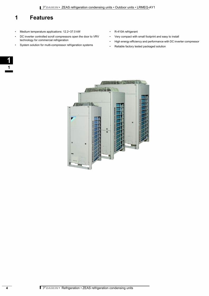
1 Features
11
ZEAS refrig Refrigeratio LRMEQ-AY1 Outdoor uni • Medium temperature applications: 12.2~37.0 kW
• DC inverter controlled scroll compressors open the door to VRV technology for commercial refrigeration
• System solution for multi-compressor refrigeration systems
• R-410A refrigerant
• Very compact with small footprint and easy to install
• High energy efficiency and performance with DC inverter compressor
• Reliable factory tested packaged solution
• Refrigeration • ZEAS refrigeration condensing units 5
• ZEAS refrigeration condensing units • Outdoor units • LRMEQ-AY1
2 Specifications
12
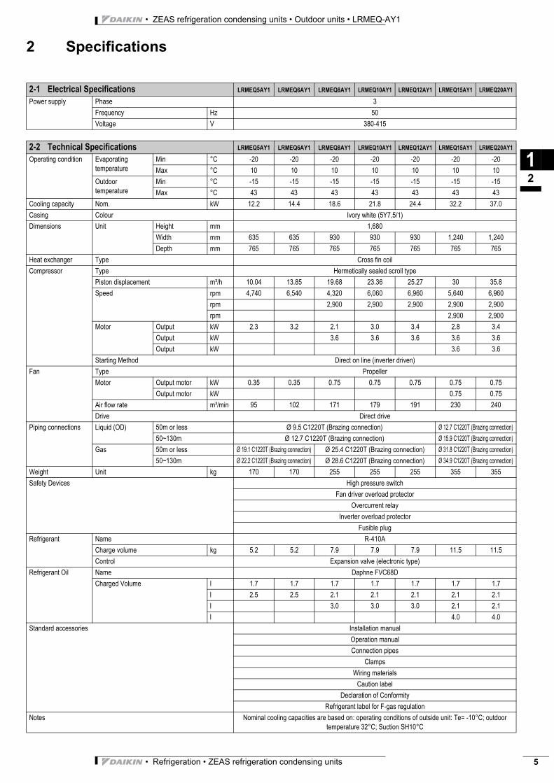
2-1 Electrical Specifications LRMEQ5AY1 LRMEQ6AY1 LRMEQ8AY1 LRMEQ10AY1 LRMEQ12AY1 LRMEQ15AY1 LRMEQ20AY1
Power supply Phase 3
Frequency Hz 50
Voltage V 380-415
2-2 Technical Specifications LRMEQ5AY1 LRMEQ6AY1 LRMEQ8AY1 LRMEQ10AY1 LRMEQ12AY1 LRMEQ15AY1 LRMEQ20AY1
Operating condition Evaporating temperature
Min °C -20 -20 -20 -20 -20 -20 -20
Max °C 10 10 10 10 10 10 10
Outdoor temperature
Min °C -15 -15 -15 -15 -15 -15 -15
Max °C 43 43 43 43 43 43 43
Cooling capacity Nom. kW 12.2 14.4 18.6 21.8 24.4 32.2 37.0
Casing Colour Ivory white (5Y7,5/1)
Dimensions Unit Height mm 1,680
Width mm 635 635 930 930 930 1,240 1,240
Depth mm 765 765 765 765 765 765 765
Heat exchanger Type Cross fin coil
Compressor Type Hermetically sealed scroll type
Piston displacement m³/h 10.04 13.85 19.68 23.36 25.27 30 35.8
Speed rpm 4,740 6,540 4,320 6,060 6,960 5,640 6,960
rpm 2,900 2,900 2,900 2,900 2,900
rpm 2,900 2,900
Motor Output kW 2.3 3.2 2.1 3.0 3.4 2.8 3.4
Output kW 3.6 3.6 3.6 3.6 3.6
Output kW 3.6 3.6
Starting Method Direct on line (inverter driven)
Fan Type Propeller
Motor Output motor kW 0.35 0.35 0.75 0.75 0.75 0.75 0.75
Output motor kW 0.75 0.75
Air flow rate m³/min 95 102 171 179 191 230 240
Drive Direct drive
Piping connections Liquid (OD) 50m or less Ø 9.5 C1220T (Brazing connection) Ø 12.7 C1220T (Brazing connection)
50~130m Ø 12.7 C1220T (Brazing connection) Ø 15.9 C1220T (Brazing connection)
Gas 50m or less Ø 19.1 C1220T (Brazing connection) Ø 25.4 C1220T (Brazing connection) Ø 31.8 C1220T (Brazing connection)
50~130m Ø 22.2 C1220T (Brazing connection) Ø 28.6 C1220T (Brazing connection) Ø 34.9 C1220T (Brazing connection)
Weight Unit kg 170 170 255 255 255 355 355
Safety Devices High pressure switch
Fan driver overload protector
Overcurrent relay
Inverter overload protector
Fusible plug
Refrigerant Name R-410A
Charge volume kg 5.2 5.2 7.9 7.9 7.9 11.5 11.5
Control Expansion valve (electronic type)
Refrigerant Oil Name Daphne FVC68D
Charged Volume l 1.7 1.7 1.7 1.7 1.7 1.7 1.7
l 2.5 2.5 2.1 2.1 2.1 2.1 2.1
l 3.0 3.0 3.0 2.1 2.1
l 4.0 4.0
Standard accessories Installation manual
Operation manual
Connection pipes
Clamps
Wiring materials
Caution label
Declaration of Conformity
Refrigerant label for F-gas regulation
Notes Nominal cooling capacities are based on: operating conditions of outside unit: Te= -10°C; outdoor temperature 32°C; Suction SH10°C
• ZEAS refrigeration condensing units • Outdoor units • LRMEQ-AY1
• Refrigeration • ZEAS refrigeration condensing units6
2 Specifications
12
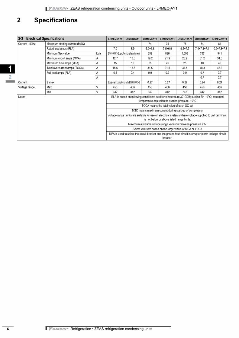
2-3 Electrical Specifications LRMEQ5AY1 LRMEQ6AY1 LRMEQ8AY1 LRMEQ10AY1 LRMEQ12AY1 LRMEQ15AY1 LRMEQ20AY1
Current - 50Hz Maximum starting current (MSC) - - 74 75 75 84 84
Rated load amps (RLA) 7.0 8.9 5.2+6.8 7.5+6.9 9.5+7.7 7.4+7.1+7.1 10.2+7.8+7.8
Minimum Ssc value kVa EN61000-3-2: professional equipment 652 896 1,093 757 941
Minimum circuit amps (MCA) A 12.7 13.6 19.2 21.9 23.9 31.2 34.8
Maximum fuse amps (MFA) A 15 15 25 25 25 40 40
Total overcurrent amps (TOCA) A 15.6 15.6 31.5 31.5 31.5 48.3 48.3
Full load amps (FLA) A 0.4 0.4 0.9 0.9 0.9 0.7 0.7
A 0.7 0.7
Current Z max Equipment complying with EN61000-3-3 0.27 0.27 0.27 0.24 0.24
Voltage range Max V 456 456 456 456 456 456 456
Min V 342 342 342 342 342 342 342
Notes RLA is based on following conditions: outdoor temperature 32°CDB; suction SH 10°C; saturated temperature equivalent to suction pressure -10°C
TOCA means the total value of each OC set
MSC means maximum current during start-up of compressor
Voltage range : units are suitable for use on electrical systems where voltage supplied to unit terminals is not below or above listed range limits.
Maximum allowable voltage range variation between phases is 2%.
Select wire size based on the larger value of MCA or TOCA
MFA is used to select the circuit breaker and the ground fault circuit interrupter (earth leakage circuit breaker)
• Refrigeration • ZEAS refrigeration condensing units 7
• ZEAS refrigeration condensing units • Outdoor units • LRMEQ-AY1
3 Nomenclature
13
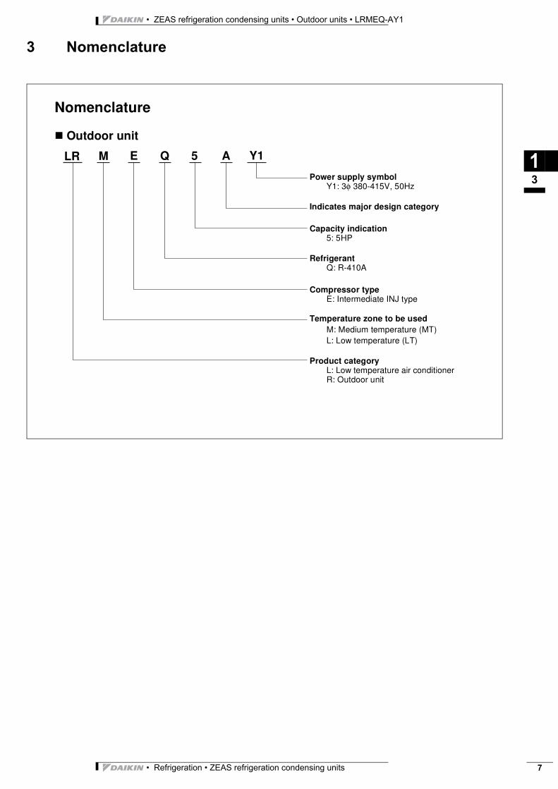
Nomenclature
� Outdoor unit
LR M E Q 5 A Y1
Power supply symbolY1: 3φ 380-415V, 50Hz
Indicates major design category
Capacity indication5: 5HP
RefrigerantQ: R-410A
Compressor typeE: Intermediate INJ type
Temperature zone to be usedM: Medium temperature (MT)L: Low temperature (LT)
Product categoryL: Low temperature air conditionerR: Outdoor unit
• ZEAS refrigeration condensing units • Outdoor units • LRMEQ-AY1
• Refrigeration • ZEAS refrigeration condensing units8
4 Electrical data
14
3D
064891
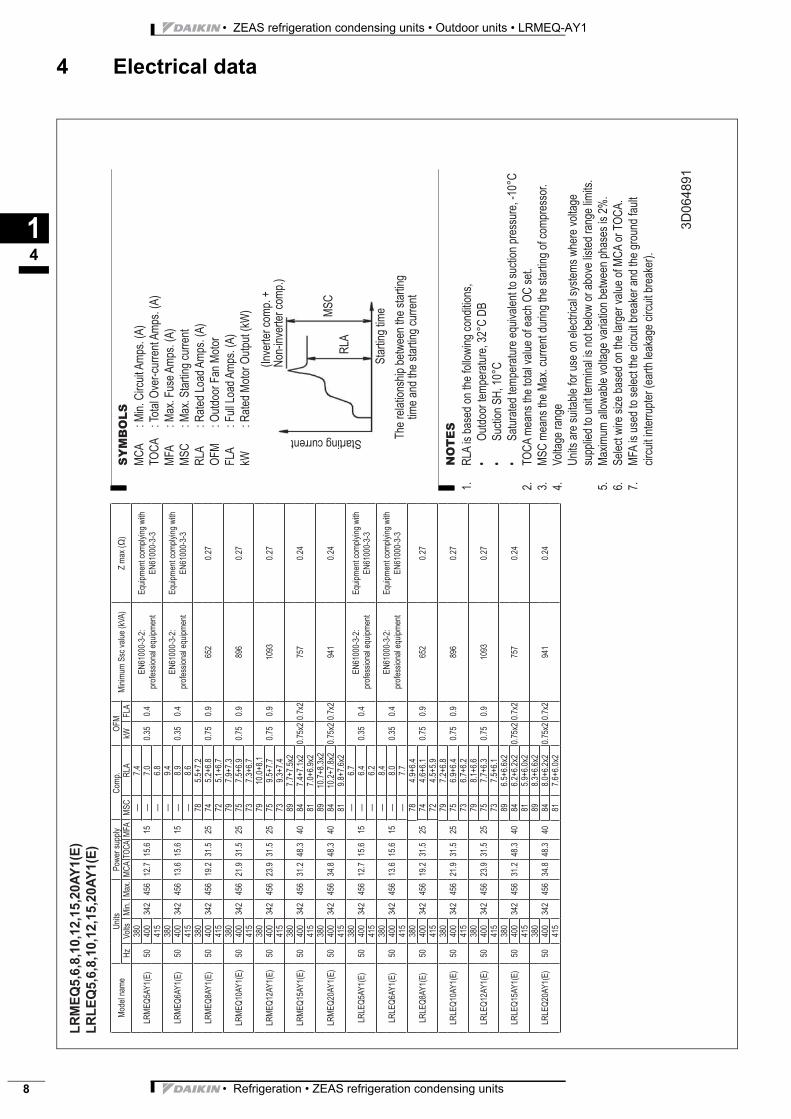
NO
TE
S
RL
A is b
ase
d o
n t
he
fo
llow
ing
co
nd
itio
ns,
Ou
tdo
or
tem
pe
ratu
re,
32
°C
DB
Su
ctio
n S
H,
10
°C
Sa
tura
ted
te
mp
era
ture
eq
uiv
ale
nt
to s
uctio
n p
ressu
re,
-10
°C
TO
CA
me
an
s t
he
to
tal va
lue
of
ea
ch
OC
se
t.
MS
C m
ea
ns t
he
Ma
x.
cu
rre
nt
du
rin
g t
he
sta
rtin
g o
f co
mp
resso
r.
Vo
lta
ge
ra
ng
e
Un
its a
re s
uita
ble
fo
r u
se
on
ele
ctr
ica
l syste
ms w
he
re v
olta
ge
su
pp
lied
to
un
it t
erm
ina
l is
no
t b
elo
w o
r a
bo
ve
lis
ted
ra
ng
e lim
its.
Ma
xim
um
allo
wa
ble
vo
lta
ge
va
ria
tio
n b
etw
ee
n p
ha
se
s is 2
%.
Se
lect
wire
siz
e b
ase
d o
n t
he
la
rge
r va
lue
of
MC
A o
r T
OC
A.
MF
A is u
se
d t
o s
ele
ct
the
circu
it b
rea
ke
r a
nd
th
e g
rou
nd
fa
ult
circu
it in
terr
up
ter
(ea
rth
le
aka
ge
circu
it b
rea
ke
r).
1.
• • •
2.
3.
4.
5.
6.
7.
LR
ME
Q5,6
,8,1
0,1
2,1
5,2
0A
Y1(E
)
LR
LE
Q5,6
,8,1
0,1
2,1
5,2
0A
Y1(E
)
Mo
de
l n
am
eU
nits
Po
we
r su
pp
lyC
om
p.
OF
MM
inim
um
Ssc v
alu
e (
kV
A)
Z m
ax (
)H
zV
olts
Min
.M
ax.
MC
AT
OC
AM
FA
MS
CR
LA
kW
FL
A
LR
ME
Q5
AY
1(E
)5
0
38
0
34
24
56
12
.71
5.6
15
—7
.4
0.3
50
.4E
N6
10
00
-3-2
:
pro
fessio
na
l e
qu
ipm
en
t
Eq
uip
me
nt
co
mp
lyin
g w
ith
EN
61
00
0-3
-34
00
—7
.0
41
5—
6.8
LR
ME
Q6
AY
1(E
)5
0
38
0
34
24
56
13
.61
5.6
15
—9
.4
0.3
50
.4E
N6
10
00
-3-2
:
pro
fessio
na
l e
qu
ipm
en
t
Eq
uip
me
nt
co
mp
lyin
g w
ith
EN
61
00
0-3
-34
00
—8
.9
41
5—
8.6
LR
ME
Q8
AY
1(E
)5
0
38
0
34
24
56
19
.23
1.5
25
78
5.5
+7
.2
0.7
50
.96
52
0.2
74
00
74
5.2
+6
.8
41
57
25
.1+
6.7
LR
ME
Q1
0A
Y1
(E)
50
38
0
34
24
56
21
.93
1.5
25
79
7.9
+7
.3
0.7
50
.98
96
0.2
74
00
75
7.5
+6
.9
41
57
37
.3+
6.7
LR
ME
Q1
2A
Y1
(E)
50
38
0
34
24
56
23
.93
1.5
25
79
10
.0+
8.1
0.7
50
.91
09
30
.27
40
07
59
.5+
7.7
41
57
39
.3+
7.4
LR
ME
Q1
5A
Y1
(E)
50
38
0
34
24
56
31
.24
8.3
40
89
7.7
+7
.5x2
0.7
5x2
0.7
x2
75
70
.24
40
08
47
.4+
7.1
x2
41
58
17
.0+
6.9
x2
LR
ME
Q2
0A
Y1
(E)
50
38
0
34
24
56
34
.84
8.3
40
89
10
.7+
8.3
x2
0.7
5x2
0.7
x2
94
10
.24
40
08
41
0.2
+7
.8x2
41
58
19
.8+
7.6
x2
LR
LE
Q5
AY
1(E
)5
0
38
0
34
24
56
12
.71
5.6
15
—6
.7
0.3
50
.4E
N6
10
00
-3-2
:
pro
fessio
na
l e
qu
ipm
en
t
Eq
uip
me
nt
co
mp
lyin
g w
ith
EN
61
00
0-3
-34
00
—6
.4
41
5—
6.2
LR
LE
Q6
AY
1(E
)5
0
38
0
34
24
56
13
.61
5.6
15
—8
.4
0.3
50
.4E
N6
10
00
-3-2
:
pro
fessio
na
l e
qu
ipm
en
t
Eq
uip
me
nt
co
mp
lyin
g w
ith
EN
61
00
0-3
-34
00
—8
.0
41
5—
7.7
LR
LE
Q8
AY
1(E
)5
0
38
0
34
24
56
19
.23
1.5
25
78
4.9
+6
.4
0.7
50
.96
52
0.2
74
00
74
4.6
+6
.1
41
57
24
.5+
5.9
LR
LE
Q1
0A
Y1
(E)
50
38
0
34
24
56
21
.93
1.5
25
79
7.2
+6
.8
0.7
50
.98
96
0.2
74
00
75
6.9
+6
.4
41
57
36
.7+
6.2
LR
LE
Q1
2A
Y1
(E)
50
38
0
34
24
56
23
.93
1.5
25
79
8.1
+6
.6
0.7
50
.91
09
30
.27
40
07
57
.7+
6.3
41
57
37
.5+
6.1
LR
LE
Q1
5A
Y1
(E)
50
38
0
34
24
56
31
.24
8.3
40
89
6.5
+6
.6x2
0.7
5x2
0.7
x2
75
70
.24
40
08
46
.2+
6.2
x2
41
58
15
.9+
6.0
x2
LR
LE
Q2
0A
Y1
(E)
50
38
0
34
24
56
34
.84
8.3
40
89
8.3
+6
.6x2
0.7
5x2
0.7
x2
94
10
.24
40
08
48
.0+
6.2
x2
41
58
17
.6+
6.0
x2
SY
MB
OL
S
MC
A
: M
in.
Circu
it A
mp
s.
(A)
TO
CA
: To
tal O
ve
r-cu
rre
nt A
mp
s.
(A)
MF
A
: M
ax.
Fu
se
Am
ps.
(A)
MS
C
: M
ax.
Sta
rtin
g c
urr
en
t
RL
A
: R
ate
d L
oa
d A
mp
s.
(A)
OF
M
: O
utd
oo
r F
an
Mo
tor
FL
A
: F
ull
Lo
ad
Am
ps.
(A)
kW
:
Ra
ted
Mo
tor
Ou
tpu
t (k
W)
(In
ve
rte
r co
mp
. +
No
n-in
ve
rte
r co
mp
.)
Th
e r
ela
tio
nsh
ip b
etw
ee
n t
he
sta
rtin
g
tim
e a
nd
th
e s
tart
ing
cu
rre
nt
Sta
rtin
g t
ime
Starting current
RL
A
MS
C
• Refrigeration • ZEAS refrigeration condensing units 9
• ZEAS refrigeration condensing units • Outdoor units • LRMEQ-AY1
5 Options
15
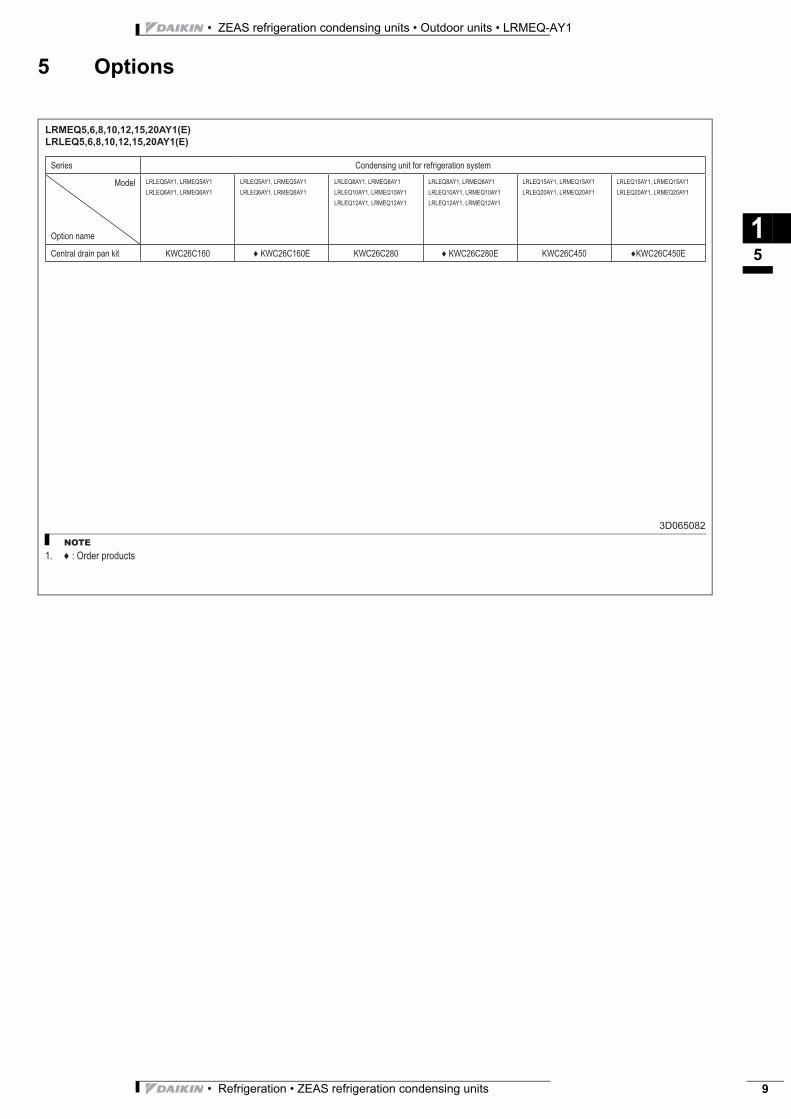
LRMEQ5,6,8,10,12,15,20AY1(E)
LRLEQ5,6,8,10,12,15,20AY1(E)
3D065082
NOTE
: Order products1.
Series Condensing unit for refrigeration system
Model
Option name
LRLEQ5AY1, LRMEQ5AY1
LRLEQ6AY1, LRMEQ6AY1
LRLEQ5AY1, LRMEQ5AY1
LRLEQ6AY1, LRMEQ6AY1
LRLEQ8AY1, LRMEQ8AY1
LRLEQ10AY1, LRMEQ10AY1
LRLEQ12AY1, LRMEQ12AY1
LRLEQ8AY1, LRMEQ8AY1
LRLEQ10AY1, LRMEQ10AY1
LRLEQ12AY1, LRMEQ12AY1
LRLEQ15AY1, LRMEQ15AY1
LRLEQ20AY1, LRMEQ20AY1
LRLEQ15AY1, LRMEQ15AY1
LRLEQ20AY1, LRMEQ20AY1
Central drain pan kit KWC26C160 KWC26C160E KWC26C280 KWC26C280E KWC26C450 KWC26C450E
• ZEAS refrigeration condensing units • Outdoor units • LRMEQ-AY1
• Refrigeration • ZEAS refrigeration condensing units10
6 Capacity tables
6 - 1 Cooling capacity tables
16
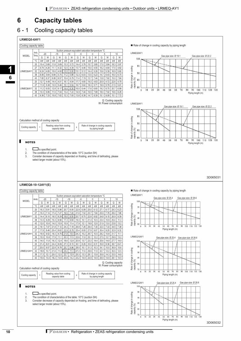
LRMEQ5-6AY1
3D065031
NOTES
is specifi ed point.
The condition of characteristics of the table: 10°C (suction SH)
Consider decrease of capacity depended on frosting, and time of defrosting, please
select larger model (about 15%).
1.
2.
3.
MODEL
Amb.
Temp.
Suction pressure equivalent saturation temperature °C
-20 -15 -10 -5 0 5 10
Q W Q W Q W Q W Q W Q W Q W
°C kW kW kW kW kW kW kW kW kW kW kW kW kW kW
LRMEQ5AY1
20 10.4 3.66 11.8 3.69 13.3 3.72 14.4 3.76 15.7 3.80 17.0 3.84 18.3 3.97
27 9.74 4.26 11.1 4.32 12.5 4.39 13.7 4.46 15.0 4.55 16.2 4.64 17.5 4.82
32 9.24 4.85 10.6 4.93 12.0 5.00 13.1 5.12 14.4 5.26 15.6 5.39 16.9 5.60
38 8.56 5.64 9.84 5.75 11.2 5.86 12.3 6.03 13.5 6.23 14.7 6.43 16.0 6.75
43 7.82 6.37 9.06 6.57 10.4 6.79 11.4 7.19 12.7 7.44 13.8 7.62 15.0 7.84
LRMEQ6AY1
20 12.7 4.49 14.4 4.51 16.1 4.54 17.7 4.60 19.3 4.63 20.9 4.72 22.6 4.79
27 11.9 5.38 13.5 5.46 15.1 5.54 16.7 5.62 18.3 5.71 19.9 5.78 21.5 5.91
32 11.2 6.05 12.8 6.17 14.4 6.30 16.0 6.44 17.6 6.60 19.2 6.75 20.7 6.99
38 10.3 6.86 11.9 7.04 13.4 7.22 14.9 7.44 16.5 7.68 18.0 7.92 19.6 8.28
43 9.36 7.33 10.8 7.62 12.3 7.93 13.8 8.38 14.7 8.39 15.1 8.08 15.1 7.72
Rate of change in cooling capacity by piping length
LRMEQ5AY1
Gas pipe size: Ø 19.1 Gas pipe size: Ø 22.2
LRMEQ6AY1
Gas pipe size: Ø 19.1 Gas pipe size: Ø 22.2
Q: Cooling capacity
W: Power consumption
Calculation method of cooling capacity
Cooling capacity =Reading value from cooling
capacity tablex
Rate of change in cooling capacity
by piping length
Ra
te o
f ch
an
ge
in
co
olin
g
ca
pa
city (
%)
Ra
te o
f ch
an
ge
in
co
olin
g
ca
pa
city (
%)
Piping length (m)
Piping length (m)
Cooling capacity table
LRMEQ8-10-12AY1(E)
3D065032
NOTES
is specifi ed point.
The condition of characteristics of the table: 10°C (suction SH)
Consider decrease of capacity depended on frosting, and time of defrosting, please
select larger model (about 15%).
1.
2.
3.
MODELAmb.
Suction pressure equivalent saturation temperature °C
-20 -15 -10 -5 0 5 10
Q W Q W Q W Q W Q W Q W Q W
°C kW kW kW kW kW kW kW kW kW kW kW kW kW kW
LRMEQ8AY1
20 16.3 5.91 18.5 5.96 20.7 6.00 22.9 6.08 25.0 6.12 27.1 6.17 29.3 6.23
27 15.3 7.14 17.4 7.27 19.5 7.40 21.6 7.52 23.7 7.64 25.9 7.76 28.0 7.86
32 14.4 8.10 16.5 8.29 18.6 8.50 20.7 8.70 22.8 8.92 24.8 9.15 26.9 9.39
38 13.3 9.29 15.3 9.56 17.3 9.84 19.3 10.1 21.4 10.5 23.4 10.9 25.4 11.3
43 12.0 10.6 14.0 10.9 15.9 11.4 17.9 12.1 19.9 12.6 21.9 13.0 23.8 13.2
LRMEQ10AY1
20 19.1 7.07 21.8 7.12 24.3 7.18 26.9 7.26 29.4 7.30 32.0 7.33 34.5 7.38
27 17.9 8.46 20.4 8.62 22.9 8.78 25.4 8.93 27.9 9.07 30.4 9.20 32.9 9.32
32 16.9 9.52 19.3 9.75 21.8 10.0 24.3 10.2 26.7 10.5 29.2 10.8 31.7 11.1
38 15.5 10.8 17.9 11.1 20.3 11.5 22.6 11.8 25.1 12.2 27.5 12.7 29.9 13.2
43 14.0 11.8 16.3 12.4 18.6 12.8 20.9 13.7 23.3 14.4 25.6 14.8 27.7 14.9
LRMEQ12AY1
20 21.4 8.01 24.4 8.09 27.3 8.15 30.1 8.26 33.0 8.31 35.8 8.36 38.7 8.41
27 20.0 9.57 22.8 9.78 25.7 9.96 28.5 10.1 31.3 10.3 34.1 10.5 36.9 10.6
32 18.8 10.7 21.6 11.0 24.4 11.3 27.2 11.6 29.9 11.9 32.7 12.2 35.5 12.5
38 17.3 12.1 20.0 12.5 22.7 12.9 25.3 13.3 28.1 13.8 30.8 14.3 33.5 14.8
43 15.6 13.0 18.2 13.6 20.8 14.2 23.2 14.9 24.9 14.9 26.9 14.9 28.1 14.5
Rate of change in cooling capacity by piping length
LRMEQ8AY1
Gas pipe size: Ø 25.4 Gas pipe size: Ø 28.6
LRMEQ10AY1 Gas pipe size: Ø 25.4 Gas pipe size: Ø 28.6
Q: Cooling capacity
W: Power consumption
Calculation method of cooling capacity
Cooling capacity =Reading value from cooling
capacity tablex
Rate of change in cooling capacity
by piping length
Ra
te o
f ch
an
ge
in
co
olin
g
ca
pa
city (
%)
Ra
te o
f ch
an
ge
in
co
olin
g
ca
pa
city (
%)
LRMEQ12AY1 Gas pipe size: Ø 25.4 Gas pipe size: Ø 28.6
Ra
te o
f ch
an
ge
in
co
olin
g
ca
pa
city (
%)
Piping length (m)
Cooling capacity table
Piping length (m)
Piping length (m)
• Refrigeration • ZEAS refrigeration condensing units 11
• ZEAS refrigeration condensing units • Outdoor units • LRMEQ-AY1
6 Capacity tables
6 - 1 Cooling capacity tables
16
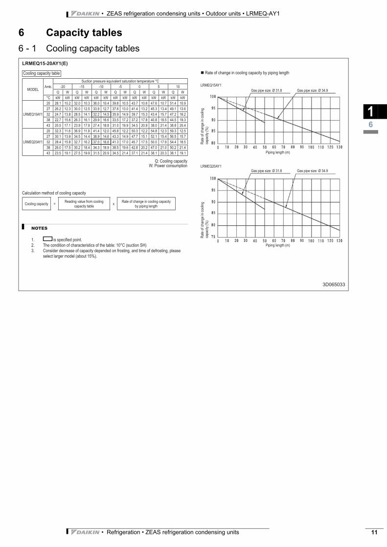
LRMEQ15-20AY1(E)
3D065033
NOTES
is specifi ed point.
The condition of characteristics of the table: 10°C (suction SH)
Consider decrease of capacity depended on frosting, and time of defrosting, please
select larger model (about 15%).
1.
2.
3.
MODELAmb.
Suction pressure equivalent saturation temperature °C
-20 -15 -10 -5 0 5 10
Q W Q W Q W Q W Q W Q W Q W
°C kW kW kW kW kW kW kW kW kW kW kW kW kW kW
LRMEQ15AY1
20 28.1 10.2 32.0 10.3 36.0 10.4 39.8 10.5 43.7 10.6 47.6 10.7 51.4 10.9
27 26.2 12.3 30.0 12.5 33.9 12.7 37.6 13.0 41.4 13.2 45.3 13.4 49.1 13.6
32 24.7 13.8 28.5 14.1 32.2 14.5 35.9 14.9 39.7 15.3 43.4 15.7 47.2 16.2
38 22.7 15.6 26.3 16.1 29.9 16.6 33.5 17.2 37.2 17.8 40.8 18.5 44.5 19.3
43 20.5 17.1 23.9 17.9 27.4 18.8 31.0 19.9 34.5 20.9 38.0 21.4 38.8 20.4
LRMEQ20AY1
20 32.3 11.6 36.9 11.9 41.4 12.0 45.8 12.2 50.3 12.2 54.8 12.3 59.3 12.5
27 30.1 13.9 34.5 14.4 38.9 14.6 43.3 14.9 47.7 15.1 52.1 15.4 56.5 15.7
32 28.4 15.8 32.7 16.2 37.0 16.6 41.3 17.0 45.7 17.5 50.0 17.9 54.4 18.5
38 26.0 17.5 30.2 18.4 34.3 18.9 38.5 19.6 42.8 20.2 47.0 21.0 50.2 21.4
43 23.5 19.1 27.5 19.9 31.5 20.9 34.5 21.4 37.1 21.4 38.1 20.3 38.1 19.1
Rate of change in cooling capacity by piping length
LRMEQ15AY1
Gas pipe size: Ø 31.8 Gas pipe size: Ø 34.9
LRMEQ20AY1
Gas pipe size: Ø 31.8 Gas pipe size: Ø 34.9
Q: Cooling capacity
W: Power consumption
Calculation method of cooling capacity
Cooling capacity =Reading value from cooling
capacity tablex
Rate of change in cooling capacity
by piping length
Ra
te o
f ch
an
ge
in
co
olin
g
ca
pa
city (
%)
Ra
te o
f ch
an
ge
in
co
olin
g
ca
pa
city (
%)
Piping length (m)
Cooling capacity table
Piping length (m)
• ZEAS refrigeration condensing units • Outdoor units • LRMEQ-AY1
• Refrigeration • ZEAS refrigeration condensing units12
7 Dimensional drawing & centre of gravity
7 - 1 Dimensional drawing
17
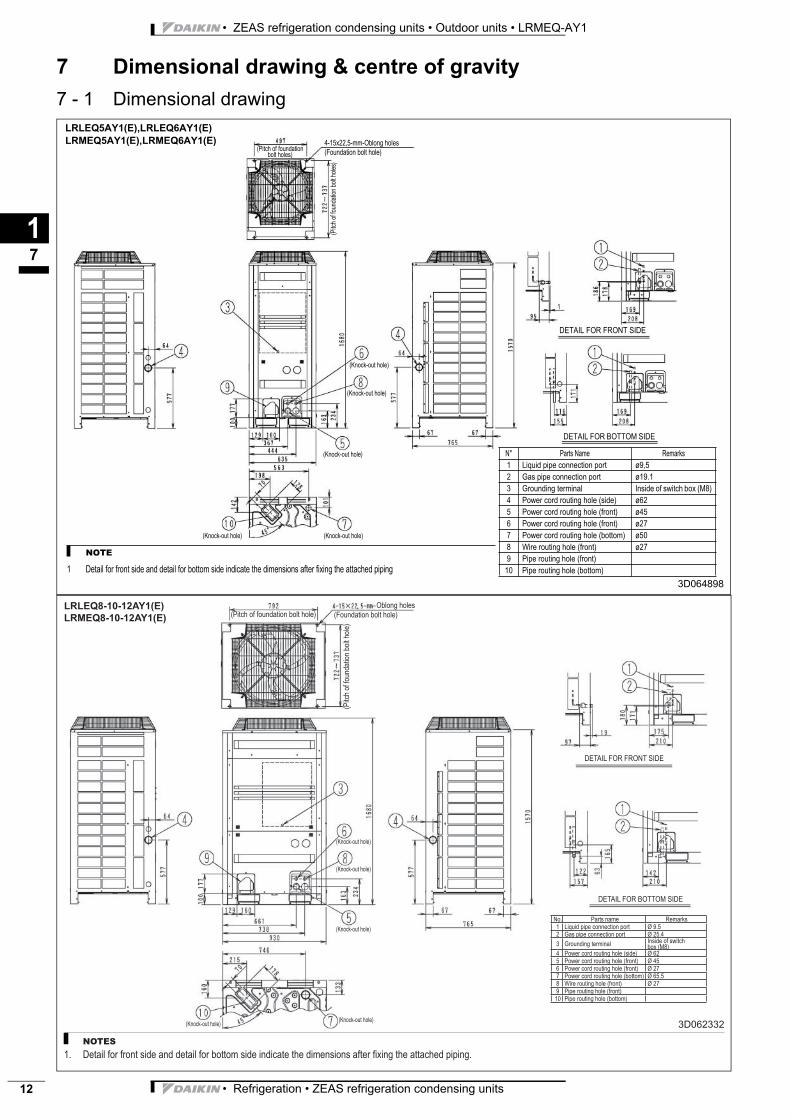
3D064898
N° Parts Name Remarks
1 Liquid pipe connection port ø9,5
2 Gas pipe connection port ø19.1
3 Grounding terminal Inside of switch box (M8)
4 Power cord routing hole (side) ø62
5 Power cord routing hole (front) ø45
6 Power cord routing hole (front) ø27
7 Power cord routing hole (bottom) ø50
8 Wire routing hole (front) ø27
9 Pipe routing hole (front)
10 Pipe routing hole (bottom)
NOTE
1 Detail for front side and detail for bottom side indicate the dimensions after fixing the attached piping
(Pitch of foundation bolt holes)
4-15x22,5-mm-Oblong holes
(Foundation bolt hole)
(Pitch o
f fo
un
da
tion b
olt h
ole
s)
(Knock-out hole)
(Knock-out hole)
(Knock-out hole)
(Knock-out hole)(Knock-out hole)
DETAIL FOR FRONT SIDE
DETAIL FOR BOTTOM SIDE
LRLEQ5AY1(E),LRLEQ6AY1(E)
LRMEQ5AY1(E),LRMEQ6AY1(E)
LRLEQ8-10-12AY1(E)
LRMEQ8-10-12AY1(E)
3D062332
NOTES
Detail for front side and detail for bottom side indicate the dimensions after fi xing the attached piping.1.
No. Parts name Remarks
1 Liquid pipe connection port Ø 9.5
2 Gas pipe connection port Ø 25.4
3 Grounding terminalInside of switch box (M8)
4 Power cord routing hole (side) Ø 62
5 Power cord routing hole (front) Ø 45
6 Power cord routing hole (front) Ø 27
7 Power cord routing hole (bottom) Ø 65.5
8 Wire routing hole (front) Ø 27
9 Pipe routing hole (front)
10 Pipe routing hole (bottom)
Oblong holes
(Foundation bolt hole)
(Pitch
of
fou
nd
atio
n b
olt h
ole
)
(Pitch of foundation bolt hole)
(Knock-out hole)
(Knock-out hole)
(Knock-out hole)
(Knock-out hole)(Knock-out hole)
DETAIL FOR FRONT SIDE
DETAIL FOR BOTTOM SIDE
• Refrigeration • ZEAS refrigeration condensing units 13
• ZEAS refrigeration condensing units • Outdoor units • LRMEQ-AY1
7 Dimensional drawing & centre of gravity
7 - 1 Dimensional drawing
17
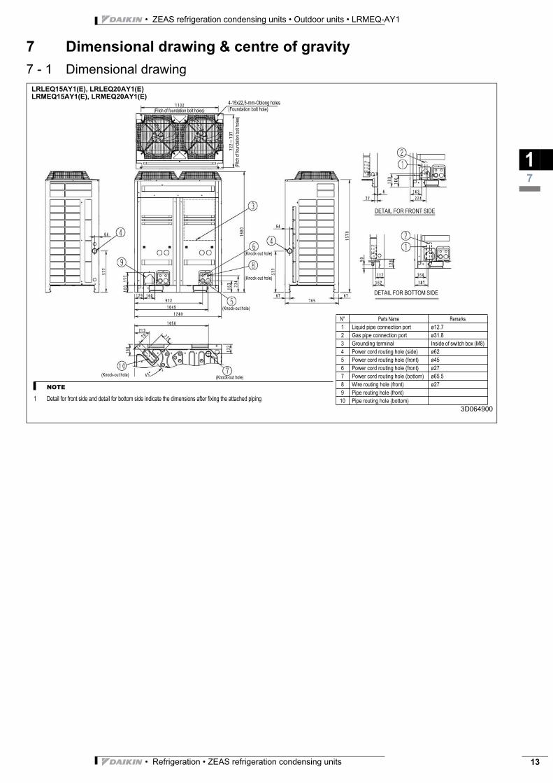
LRLEQ15AY1(E), LRLEQ20AY1(E)
LRMEQ15AY1(E), LRMEQ20AY1(E)
3D064900
N° Parts Name Remarks
1 Liquid pipe connection port ø12.7
2 Gas pipe connection port ø31.8
3 Grounding terminal Inside of switch box (M8)
4 Power cord routing hole (side) ø62
5 Power cord routing hole (front) ø45
6 Power cord routing hole (front) ø27
7 Power cord routing hole (bottom) ø65.5
8 Wire routing hole (front) ø27
9 Pipe routing hole (front)
10 Pipe routing hole (bottom)
NOTE
1 Detail for front side and detail for bottom side indicate the dimensions after fixing the attached piping
(Pitch of foundation bolt holes)
(Pitch o
f fo
un
da
tion b
olt h
ole
s)
(Knock-out hole)
(Knock-out hole)
(Knock-out hole)
(Knock-out hole)(Knock-out hole)
DETAIL FOR FRONT SIDE
DETAIL FOR BOTTOM SIDE
4-15x22,5-mm-Oblong holes
(Foundation bolt hole)
• ZEAS refrigeration condensing units • Outdoor units • LRMEQ-AY1
• Refrigeration • ZEAS refrigeration condensing units14
7 Dimensional drawing & centre of gravity
7 - 1 Dimensional drawing
17
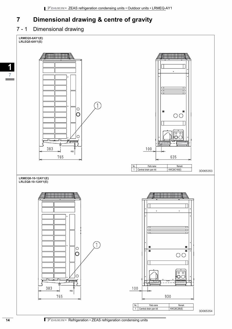
LRMEQ5-6AY1(E)
LRLEQ5-6AY1(E)
3D065353
No. Parts name Remark
1 Central drain pan kit KWC26C160(E)
LRMEQ8-10-12AY1(E)
LRLEQ8-10-12AY1(E)
3D065354
No. Parts name Remark
1 Central drain pan kit KWC26C280(E)
• Refrigeration • ZEAS refrigeration condensing units 15
• ZEAS refrigeration condensing units • Outdoor units • LRMEQ-AY1
7 Dimensional drawing & centre of gravity
7 - 1 Dimensional drawing
17
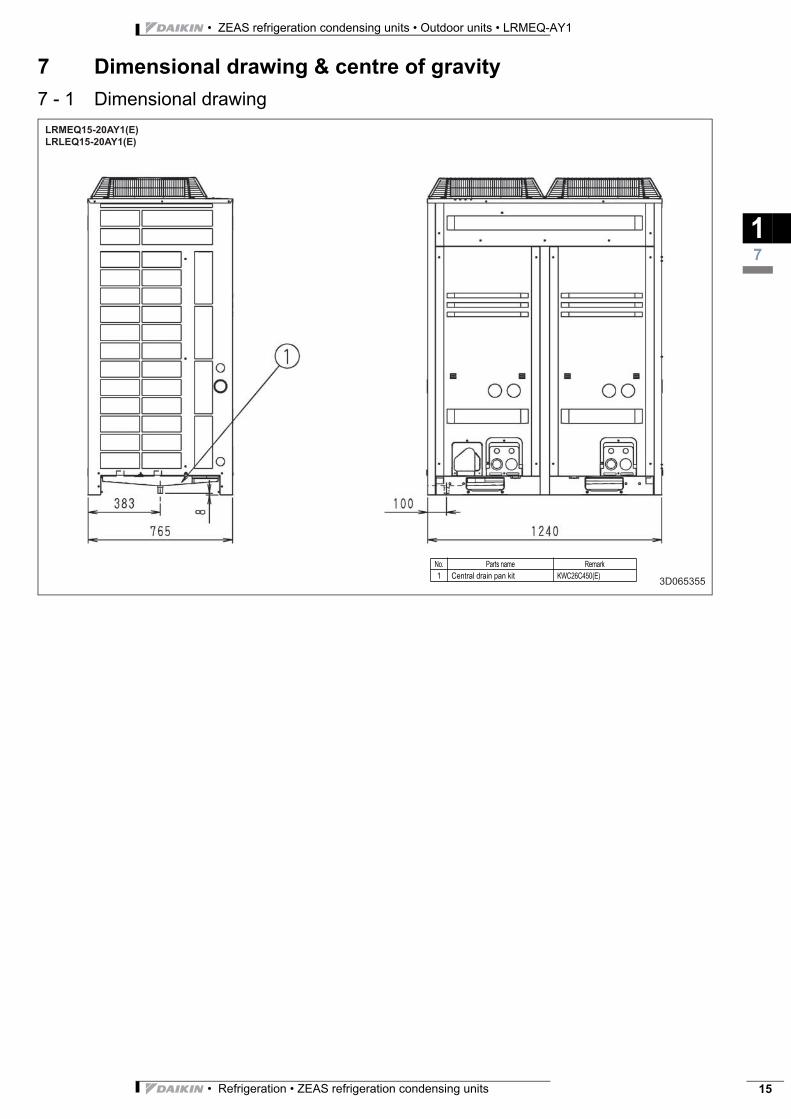
LRMEQ15-20AY1(E)
LRLEQ15-20AY1(E)
3D065355
No. Parts name Remark
1 Central drain pan kit KWC26C450(E)
• ZEAS refrigeration condensing units • Outdoor units • LRMEQ-AY1
• Refrigeration • ZEAS refrigeration condensing units16
7 Dimensional drawing & centre of gravity
7 - 2 Centre of gravity
17
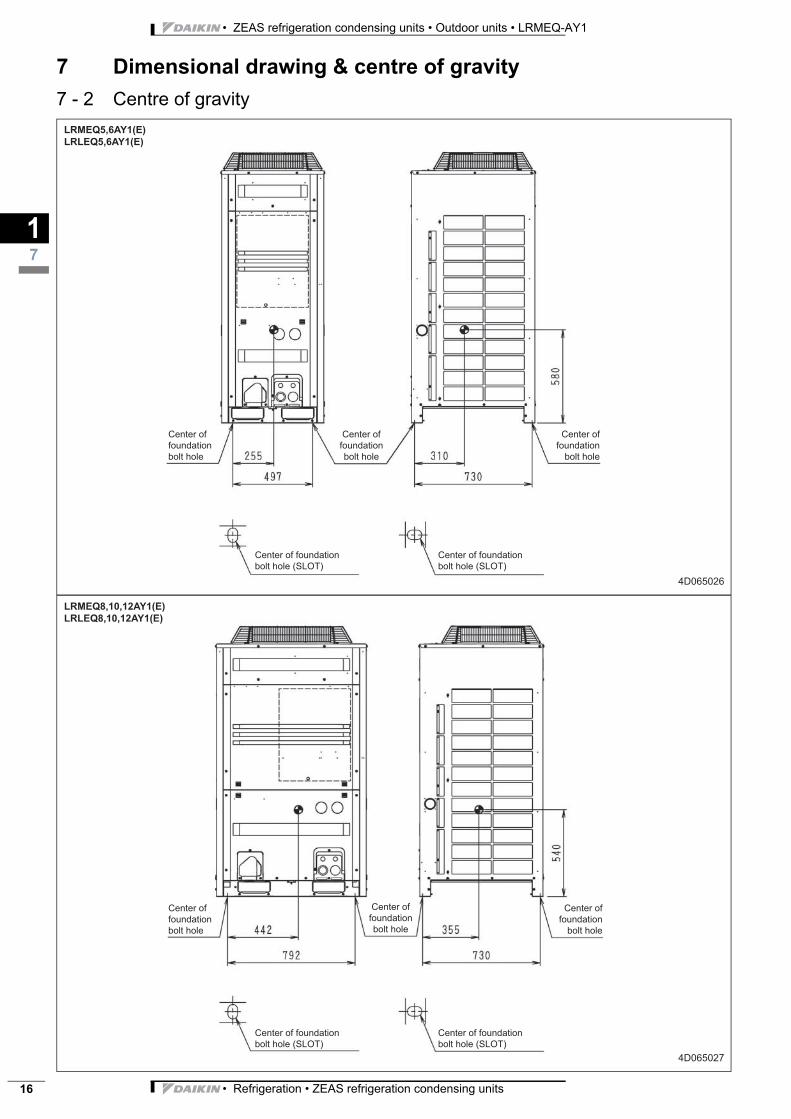
LRMEQ5,6AY1(E)
LRLEQ5,6AY1(E)
4D065026
Center of
foundation
bolt hole
Center of
foundation
bolt hole
Center of
foundation
bolt hole
Center of foundation
bolt hole (SLOT)
Center of foundation
bolt hole (SLOT)
LRMEQ8,10,12AY1(E)
LRLEQ8,10,12AY1(E)
4D065027
Center of
foundation
bolt hole
Center of
foundation
bolt hole
Center of
foundation
bolt hole
Center of foundation
bolt hole (SLOT)
Center of foundation
bolt hole (SLOT)
• Refrigeration • ZEAS refrigeration condensing units 17
• ZEAS refrigeration condensing units • Outdoor units • LRMEQ-AY1
7 Dimensional drawing & centre of gravity
7 - 2 Centre of gravity
17
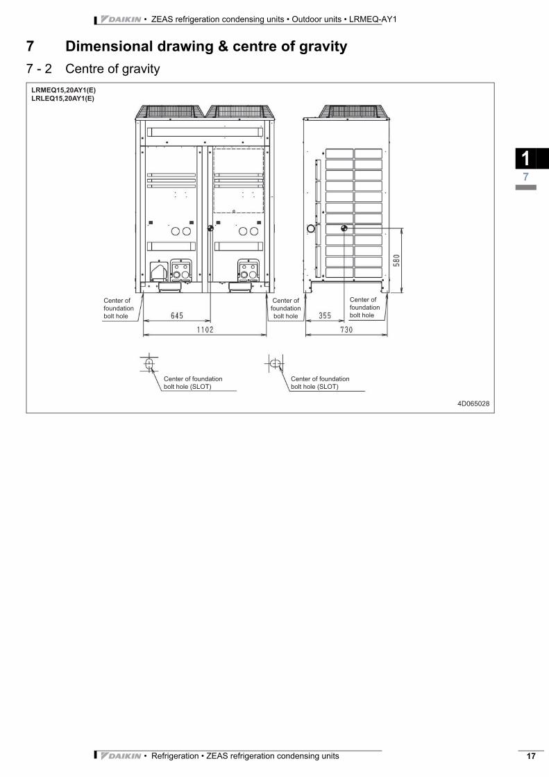
LRMEQ15,20AY1(E)
LRLEQ15,20AY1(E)
4D065028
Center of
foundation
bolt hole
Center of
foundation
bolt hole
Center of
foundation
bolt hole
Center of foundation
bolt hole (SLOT)
Center of foundation
bolt hole (SLOT)
• ZEAS refrigeration condensing units • Outdoor units • LRMEQ-AY1
• Refrigeration • ZEAS refrigeration condensing units18
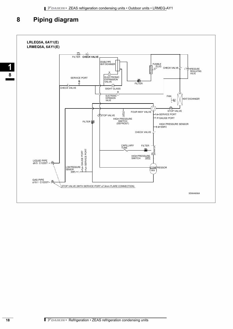
8 Piping diagram
18
LRLEQ5A, 6AY1(E)LRMEQ5A, 6AY1(E)
FILTER CHECK VALVE
DOUBLE PIPE HEAT EXCHANGER
SERVICE PORT
CHECK VALVE
ELECTRONIC EXPANSION VALVE
SIGHT GLASS
ELECTRONIC EXPANSION VALVE
FILTER
RECE
IVER
FUSIBLEPLUG
CHECK VALVE PRESSURE REGULATING VALVE
FAN
MHEAT EXCHANGER
FILTER
STOP VALVE
HIGH PRESSURE SWITCH
(DEFROST)
FOUR WAY VALVE STOP VALVE
SERVICE PORT
GAUGE PORT
HIGH PRESSURE SENSORSENPH
HP
S
CHECK VALVE
FILTERCAPILLARY TUBE
OIL
SEPA
RATO
RHIGH PRESSURE SWITCH HPS
COMPRESSORINV
LOW PRESSURE SENSOR
SENPL
GA
UG
E P
OR
T
SE
RV
ICE
PO
RT
LIQUID PIPE φ9.5 C1220T
GAS PIPE φ19.1 C1220T
STOP VALVE (WITH SERVICE PORT φ7.9mm FLARE CONNECTION)
3D064606A
CHECK VALVE
• Refrigeration • ZEAS refrigeration condensing units 19
• ZEAS refrigeration condensing units • Outdoor units • LRMEQ-AY1
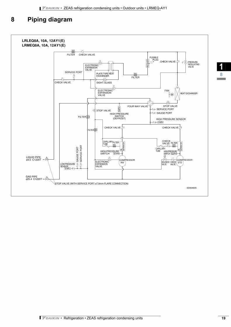
8 Piping diagram
18
LRLEQ8A, 10A, 12AY1(E)LRMEQ8A, 10A, 12AY1(E)
FILTER CHECK VALVE
ELECTRONIC EXPANSION VALVE
SERVICE PORT
CHECK VALVE
PLATE TYPE HEAT EXCHANGER
SIGHT GLASS
ELECTRONIC EXPANSION VALVE
FILTER
RECE
IVER
FUSIBLEPLUG
CHECK VALVE PRESSURE REGULATING VALVE
FAN
M HEAT EXCHANGER
FILTER
STOP VALVEHIGH PRESSURE
SWITCH (DEFROST)
FOUR WAY VALVE STOP VALVESERVICE PORT
GAUGE PORT
HIGH PRESSURE SENSORS1NPH
S4P
H
CHECK VALVE
FILTERCAPILLARY TUBE
OIL
SEPA
RATO
R
HIGH PRESSURE SWITCH
COMPRESSORINV
LOW PRESSURE SENSOR
S1NPL
GA
UG
E P
OR
T
SE
RV
ICE
PO
RT
LIQUID PIPE φ9.5 C1220T
GAS PIPE φ25.4 C1220T
STOP VALVE (WITH SERVICE PORT φ7.9mm FLARE CONNECTION)
CHECK VALVEFILTER
S1PH
ELECTRONIC EXPANSION VALVE
OIL
SEPA
RATO
RFILTER
CAPILLARY TUBE HIGH PRESSURE
SWITCH S2PH
COMPRESSORSTD
CHECK VALVE
CHECK VALVE
SOLENOID VALVE
3D064605
SV
• ZEAS refrigeration condensing units • Outdoor units • LRMEQ-AY1
• Refrigeration • ZEAS refrigeration condensing units20
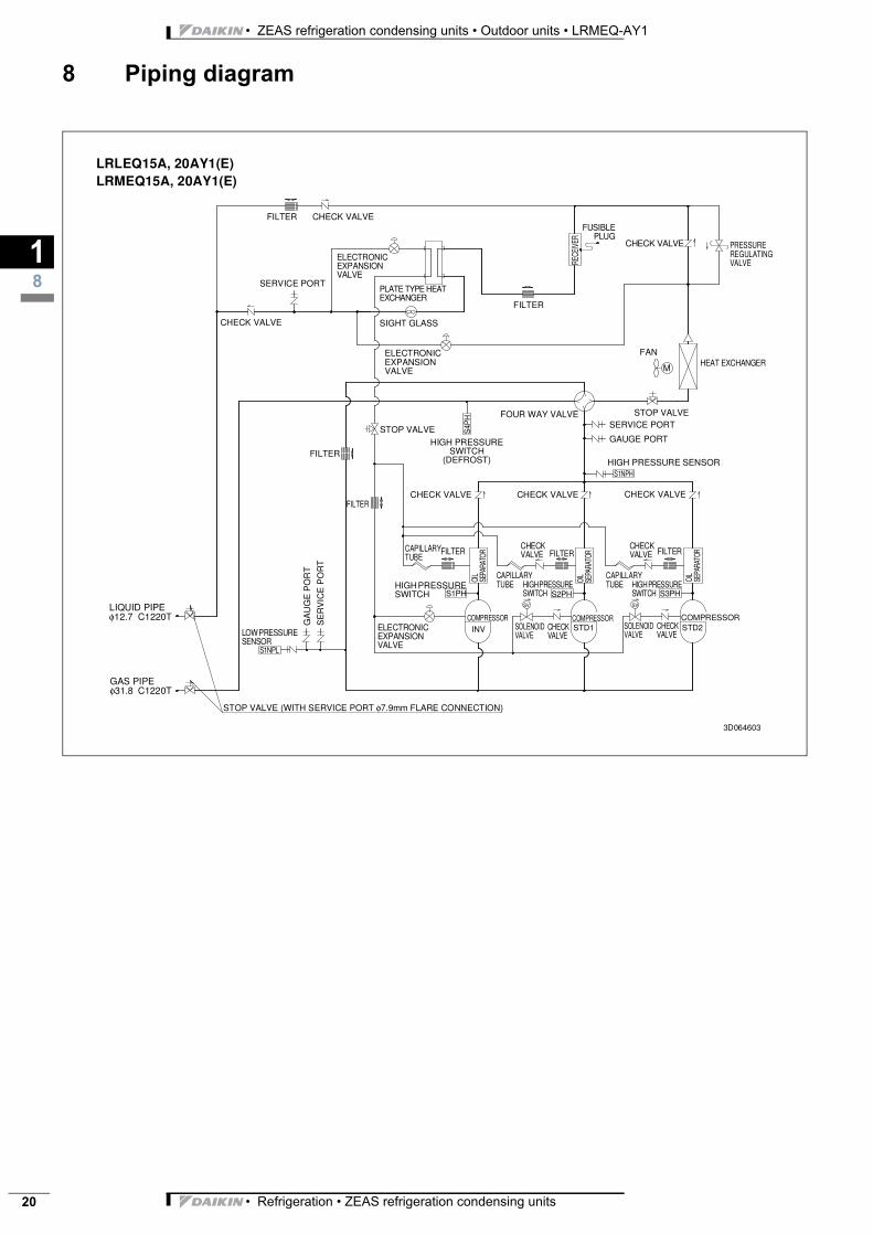
8 Piping diagram
18
LRLEQ15A, 20AY1(E)LRMEQ15A, 20AY1(E)
FILTER CHECK VALVE
ELECTRONIC EXPANSION VALVE
SERVICE PORT
CHECK VALVE
PLATE TYPE HEAT EXCHANGER
SIGHT GLASS
ELECTRONIC EXPANSION VALVE
FILTER
RECE
IVER
FUSIBLEPLUG
CHECK VALVE PRESSURE REGULATING VALVE
FAN
MHEAT EXCHANGER
FILTER
STOP VALVEHIGH PRESSURE
SWITCH (DEFROST)
FOUR WAY VALVE STOP VALVESERVICE PORT
GAUGE PORT
HIGH PRESSURE SENSORS1NPH
S4P
H
CHECK VALVE
FILTERCAPILLARY TUBE
OIL
SEPA
RATO
R
HIGH PRESSURE SWITCH
COMPRESSORINVLOW PRESSURE
SENSORS1NPL
GA
UG
E P
OR
T
SE
RV
ICE
PO
RT
LIQUID PIPE φ12.7 C1220T
GAS PIPE φ31.8 C1220T
STOP VALVE (WITH SERVICE PORT φ7.9mm FLARE CONNECTION)
CHECK VALVEFILTER
S1PH
ELECTRONIC EXPANSION VALVE
OIL
SEPA
RATO
R
CAPILLARY TUBE HIGH PRESSURE
SWITCH S3PH
COMPRESSORSTD2
CHECK VALVE
CHECK VALVE
SOLENOID VALVE
3D064603
CHECK VALVE
FILTER
OIL
SEPA
RATO
R
CAPILLARY TUBE HIGH PRESSURE
SWITCH S2PH
COMPRESSORSTD1
CHECK VALVE
CHECK VALVE
SOLENOID VALVE
FILTER
SV SV
• Refrigeration • ZEAS refrigeration condensing units 21
• ZEAS refrigeration condensing units • Outdoor units • LRMEQ-AY1
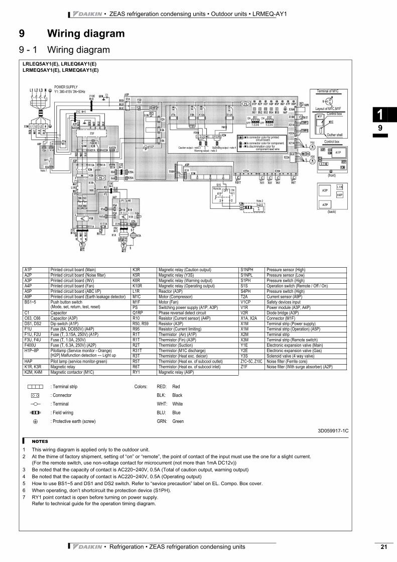
9 Wiring diagram
9 - 1 Wiring diagram
19
LRLEQ5AY1(E), LRLEQ6AY1(E)
LRMEQ5AY1(E), LRMEQ6AY1(E)
3D059917-1C
NOTES
1 This wiring diagram is applied only to the outdoor unit.
2 At the thime of factory shipment, setting of “on” or “remote”, the point of contact of the input must use the one for a slight current.
(For the remote switch, use non-voltage contact for microcurrent (not more than 1mA DC12v))
3 Be noted that the capacity of contact is AC220~240V, 0.5A (Total of caution output, warning output)
4 Be noted that the capacity of contact is AC220~240V, 0.5A (Operating output)
5 How to use BS1~5 and DS1 and DS2 switch. Refer to “sevice precaution” label on EL. Compo. Box cover.
6 When operating, don’t shortcircuit the protection device (S1PH).
7 RY1 point contact is open before turning on power supply.
Refer to technical guide for the operation timing diagram.
A1P Printed circuit board (Main) K3R Magnetic relay (Caution output) S1NPH Pressure sensor (High)
A2P Printed circuit board (Noise filter) K5R Magnetic relay (Y3S) S1NPL Pressure sensor (Low)
A3P Printed circuit board (INV) K6R Magnetic relay (Warning output) S1PH Pressure switch (High)
A4P Printed circuit board (Fan) K10R Magnetic relay (Operating output) S1S Operation switch (Remote / Off / On)
A5P Printed circuit board (ABC I/P) L1R Reactor (A3P) S4PH Pressure switch (High)
A9P Printed circuit board (Earth leakage detector) M1C Motor (Compressor) T2A Current sensor (A9P)
BS1~5 Push button switch
(Mode, set, return, test, reset)
M1F Motor (Fan) V1CP Safety devices input
PS Switching power supply (A1P, A3P) V1R Power module (A3P, A4P)
C1 Capacitor Q1RP Phase reversal detect circuit V2R Diode bridge (A3P)
C63, C66 Capacitor (A3P) R10 Resistor (Current sensor) (A4P) X1A, X2A Connector (M1F)
DS1, DS2 Dip switch (A1P) R50, R59 Resistor (A3P) X1M Terminal strip (Power supply)
F1U Fuse (8A, DC650V) (A4P) R95 Resistor (Current limiting) X1M Terminal strip (Operation) (A5P)
F1U, F2U Fuse (T, 3.15A, 250V) (A1P) R1T Thermistor (Air) (A1P) X2M Terminal strip
F3U, F4U Fuse (T, 1.0A, 250V) R1T Thermistor (Fin) (A3P) X3M Terminal strip (Remote switch)
F400U Fuse (T, 6.3A, 250V) (A2P) R2T Thermistor (Suction) Y1E Electronic expansion valve (Main)
H1P~8P Pilotlamp (Service monitor - Orange)
[H2P] Malfunction detection --- Light up
R31T Thermistor (M1C discharge) Y2E Electronic expansion valve (Gas)
R3T Thermistor (Heat exc. deicer) Y3S Solenoid valve (4 way valve)
HAP Pilot lamp (service monitor-green) R5T Thermistor (Heat ex. of subcool outlet) Z1C~5C, Z10C Noise filter (Ferrite core)
K1R, K3R Magnetic relay R6T Thermistor (Heat ex. of subcool inlet) Z1F Noise filter (With surge absorber) (A2P)
K2M, K4M Magnetic contactor (M1C) RY1 Magnetic relay (A9P)
: Terminal strip Colors: RED: Red
: Connector BLK: Black
: Terminal WHT: White
: Field wiring BLU: Blue
: Protective earth (screw) GRN: Green
POWER SUPPLY
Y1: 380-415V 3N~50Hz Terminal of M1C
Layout of M1C,M1F
Control box
Outher shell
Control box
Is connector color for printed circuit board.
Is connector color for component.
Is discrimination color for component lead wire
(front)
(back)
ON
OFF
ON
OFF
ONOFFRemote
Note 2
Switch
Caution output - note 3
Warning output - note 3
Operating output - note 4
Note 7
• ZEAS refrigeration condensing units • Outdoor units • LRMEQ-AY1
• Refrigeration • ZEAS refrigeration condensing units22
9 Wiring diagram
9 - 1 Wiring diagram
19
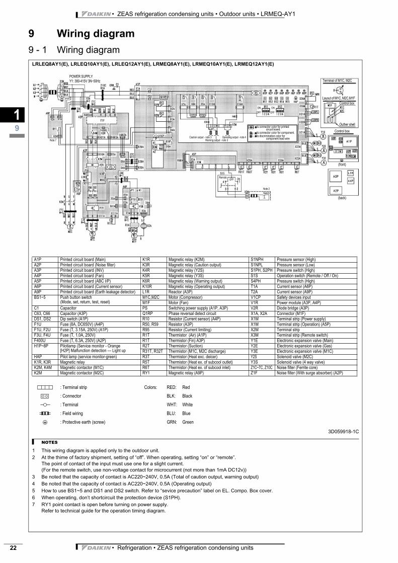
LRLEQ8AY1(E), LRLEQ10AY1(E), LRLEQ12AY1(E), LRMEQ8AY1(E), LRMEQ10AY1(E), LRMEQ12AY1(E)
3D059918-1C
NOTES
1 This wiring diagram is applied only to the outdoor unit.
2 At the thime of factory shipment, setting of “off”. When operating, setting “on” or “remote”.
The point of contact of the input must use one for a slight current.
(For the remote switch, use non-voltage contact for microcurrent (not more than 1mA DC12v))
3 Be noted that the capacity of contact is AC220~240V, 0.5A (Total of caution output, warning output)
4 Be noted that the capacity of contact is AC220~240V, 0.5A (Operating output)
5 How to use BS1~5 and DS1 and DS2 switch. Refer to “sevice precaution” label on EL. Compo. Box cover.
6 When operating, don’t shortcircuit the protection device (S1PH).
7 RY1 point contact is open before turning on power supply.
Refer to technical guide for the operation timing diagram.
A1P Printed circuit board (Main) K1R Magnetic relay (K2M) S1NPH Pressure sensor (High)
A2P Printed circuit board (Noise filter) K3R Magnetic relay (Caution output) S1NPL Pressure sensor (Low)
A3P Printed circuit board (INV) K4R Magnetic relay (Y2S) S1PH, S2PH Pressure switch (High)
A4P Printed circuit board (Fan) K5R Magnetic relay (Y3S) S1S Operation switch (Remote / Off / On)
A5P Printed circuit board (ABC I/P) K6R Magnetic relay (Warning output) S4PH Pressure switch (High)
A6P Printed circuit board (Current sensor) K10R Magnetic relay (Operating output) T1A Current sensor (A6P)
A9P Printed circuit board (Earth leakage detector) L1R Reactor (A3P) T2A Current sensor (A9P)
BS1~5 Push button switch
(Mode, set, return, test, reset)
M1C,M2C Motor (Compressor) V1CP Safety devices input
M1F Motor (Fan) V1R Power module (A3P, A4P)
C1 Capacitor PS Switching power supply (A1P, A3P) V2R Diode bridge (A3P)
C63, C66 Capacitor (A3P) Q1RP Phase reversal detect circuit X1A, X2A Connector (M1F)
DS1, DS2 Dip switch (A1P) R10 Resistor (Current sensor) (A4P) X1M Terminal strip (Power supply)
F1U Fuse (8A, DC650V) (A4P) R50, R59 Resistor (A3P) X1M Terminal strip (Operation) (A5P)
F1U, F2U Fuse (T, 3.15A, 250V) (A1P) R95 Resistor (Current limiting) X2M Terminal strip
F3U, F4U Fuse (T, 1.0A, 250V) R1T Thermistor (Air) (A1P) X3M Terminal strip (Remote switch)
F400U Fuse (T, 6.3A, 250V) (A2P) R1T Thermistor (Fin) A3P) Y1E Electronic expansion valve (Main)
H1P~8P Pilotlamp (Service monitor - Orange
[H2P] Malfunction detection --- Light up
R2T Thermistor (Suction) Y2E Electronic expansion valve (Gas)
R31T, R32T Thermistor (M1C, M2C discharge) Y3E Electronic expansion valve (M1C)
HAP Pilot lamp (service monitor-green) R3T Thermistor (Heat exc. deicer) Y2S Solenoid valve (M2C)
K1R, K3R Magnetic relay R5T Thermistor (Heat ex. of subcool outlet) Y3S Solenoid valve (4 way valve)
K2M, K4M Magnetic contactor (M1C) R6T Thermistor (Heat ex. of subcool inlet) Z1C~7C, Z10C Noise filter (Ferrite core)
K2M Magnetic contactor (M2C) RY1 Magnetic relay (A9P) Z1F Noise filter (With surge absorber) (A2P)
: Terminal strip Colors: RED: Red
: Connector BLK: Black
: Terminal WHT: White
: Field wiring BLU: Blue
: Protective earth (screw) GRN: Green
POWER SUPPLY
Y1: 380-415V 3N~50Hz Terminal of M1C, M2C
Layout of M1C, M2C,M1F
Control box
Outher shell
Control box
Is connector color for printed circuit board.
Is connector color for component.
Is discrimination color for component lead wire
(front)
(back)
ON
OFF
ON
OFF
ONOFFRemote
Note 2
Switch
Caution output - note 3
Warning output - note 3
Operating output - note 4
Note 7
• Refrigeration • ZEAS refrigeration condensing units 23
• ZEAS refrigeration condensing units • Outdoor units • LRMEQ-AY1
9 Wiring diagram
9 - 1 Wiring diagram
19
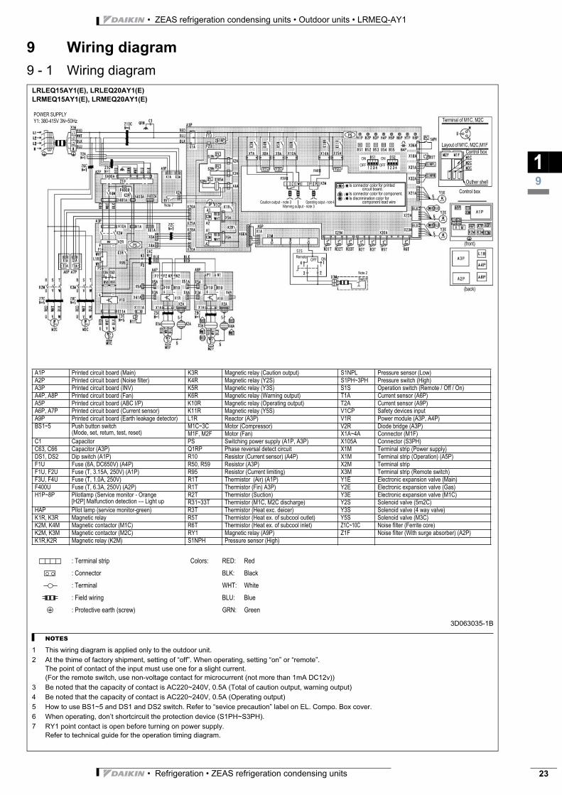
LRLEQ15AY1(E), LRLEQ20AY1(E)
LRMEQ15AY1(E), LRMEQ20AY1(E)
3D063035-1B
NOTES
1 This wiring diagram is applied only to the outdoor unit.
2 At the thime of factory shipment, setting of “off”. When operating, setting “on” or “remote”.
The point of contact of the input must use one for a slight current.
(For the remote switch, use non-voltage contact for microcurrent (not more than 1mA DC12v))
3 Be noted that the capacity of contact is AC220~240V, 0.5A (Total of caution output, warning output)
4 Be noted that the capacity of contact is AC220~240V, 0.5A (Operating output)
5 How to use BS1~5 and DS1 and DS2 switch. Refer to “sevice precaution” label on EL. Compo. Box cover.
6 When operating, don’t shortcircuit the protection device (S1PH~S3PH).
7 RY1 point contact is open before turning on power supply.
Refer to technical guide for the operation timing diagram.
A1P Printed circuit board (Main) K3R Magnetic relay (Caution output) S1NPL Pressure sensor (Low)
A2P Printed circuit board (Noise filter) K4R Magnetic relay (Y2S) S1PH~3PH Pressure switch (High)
A3P Printed circuit board (INV) K5R Magnetic relay (Y3S) S1S Operation switch (Remote / Off / On)
A4P, A8P Printed circuit board (Fan) K6R Magnetic relay (Warning output) T1A Current sensor (A6P)
A5P Printed circuit board (ABC I/P) K10R Magnetic relay (Operating output) T2A Current sensor (A9P)
A6P, A7P Printed circuit board (Current sensor) K11R Magnetic relay (Y5S) V1CP Safety devices input
A9P Printed circuit board (Earth leakage detector) L1R Reactor (A3P) V1R Power module (A3P, A4P)
BS1~5 Push button switch
(Mode, set, return, test, reset)
M1C~3C Motor (Compressor) V2R Diode bridge (A3P)
M1F, M2F Motor (Fan) X1A~4A Connector (M1F)
C1 Capacitor PS Switching power supply (A1P, A3P) X105A Connector (S3PH)
C63, C66 Capacitor (A3P) Q1RP Phase reversal detect circuit X1M Terminal strip (Power supply)
DS1, DS2 Dip switch (A1P) R10 Resistor (Current sensor) (A4P) X1M Terminal strip (Operation) (A5P)
F1U Fuse (8A, DC650V) (A4P) R50, R59 Resistor (A3P) X2M Terminal strip
F1U, F2U Fuse (T, 3.15A, 250V) (A1P) R95 Resistor (Current limiting) X3M Terminal strip (Remote switch)
F3U, F4U Fuse (T, 1.0A, 250V) R1T Thermistor (Air) (A1P) Y1E Electronic expansion valve (Main)
F400U Fuse (T, 6.3A, 250V) (A2P) R1T Thermistor (Fin) A3P) Y2E Electronic expansion valve (Gas)
H1P~8P Pilotlamp (Service monitor - Orange
[H2P] Malfunction detection --- Light up
R2T Thermistor (Suction) Y3E Electronic expansion valve (M1C)
R31~33T Thermistor (M1C, M2C discharge) Y2S Solenoid valve (5m2C)
HAP Pilot lamp (service monitor-green) R3T Thermistor (Heat exc. deicer) Y3S Solenoid valve (4 way valve)
K1R, K3R Magnetic relay R5T Thermistor (Heat ex. of subcool outlet) Y5S Solenoid valve (M3C)
K2M, K4M Magnetic contactor (M1C) R6T Thermistor (Heat ex. of subcool inlet) Z1C~10C Noise filter (Ferrite core)
K2M, K3M Magnetic contactor (M2C) RY1 Magnetic relay (A9P) Z1F Noise filter (With surge absorber) (A2P)
K1R,K2R Magnetic relay (K2M) S1NPH Pressure sensor (High)
: Terminal strip Colors: RED: Red
: Connector BLK: Black
: Terminal WHT: White
: Field wiring BLU: Blue
: Protective earth (screw) GRN: Green
POWER SUPPLY
Y1: 380-415V 3N~50Hz Terminal of M1C, M2C
Layout of M1C, M2C,M1F
Control box
Outher shell
Control box
Is connector color for printed circuit board.
Is connector color for component.
Is discrimination color for component lead wire
(front)
(back)
ON
OFF
ON
OFF
ONOFFRemote
Note 2
Switch
Caution output - note 3
Warning output - note 3
Operating output - note 4Note 7
• ZEAS refrigeration condensing units • Outdoor units • LRMEQ-AY1
• Refrigeration • ZEAS refrigeration condensing units24
9 Wiring diagram
9 - 2 External connection diagram
19
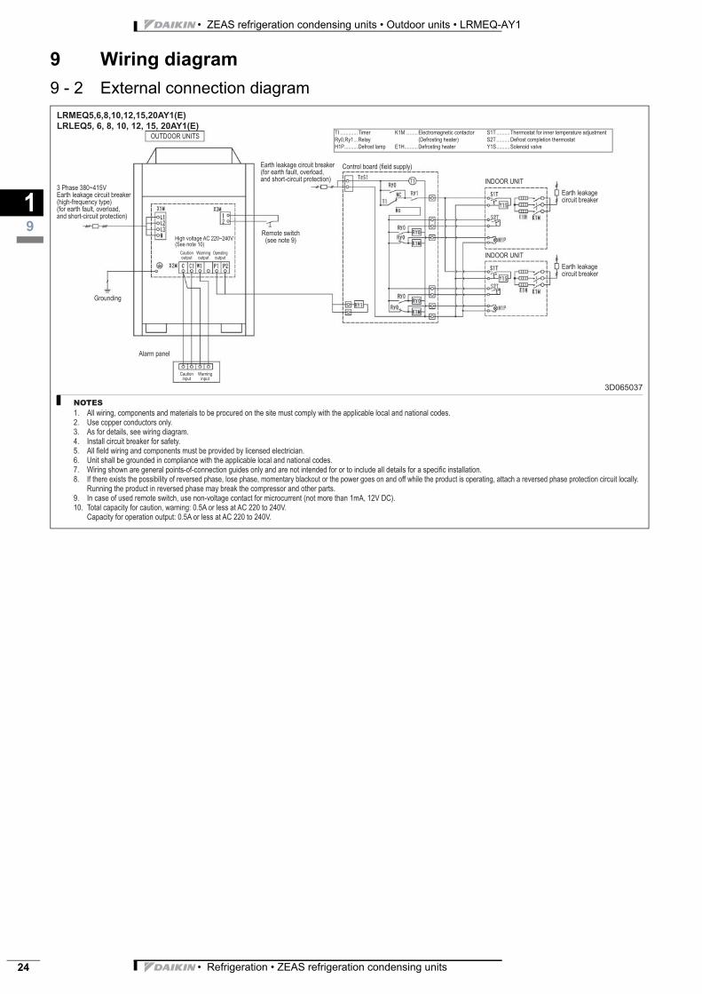
LRMEQ5,6,8,10,12,15,20AY1(E)
LRLEQ5, 6, 8, 10, 12, 15, 20AY1(E)
3D065037
NOTES
All wiring, components and materials to be procured on the site must comply with the applicable local and national codes.
Use copper conductors only.
As for details, see wiring diagram.
Install circuit breaker for safety.
All fi eld wiring and components must be provided by licensed electrician.
Unit shall be grounded in compliance with the applicable local and national codes.
Wiring shown are general points-of-connection guides only and are not intended for or to include all details for a specifi c installation.
If there exists the possibility of reversed phase, lose phase, momentary blackout or the power goes on and off while the product is operating, attach a reversed phase protection circuit locally.
Running the product in reversed phase may break the compressor and other parts.
In case of used remote switch, use non-voltage contact for microcurrent (not more than 1mA, 12V DC).
Total capacity for caution, warning: 0.5A or less at AC 220 to 240V.
Capacity for operation output: 0.5A or less at AC 220 to 240V.
1.
2.
3.
4.
5.
6.
7.
8.
9.
10.
OUTDOOR UNITS
3 Phase 380~415V
Earth leakage circuit breaker
(high-frequency type)
(for earth fault, overload,
and short-circuit protection)
Grounding
Alarm panel
Caution
input
Warning
input
High voltage AC 220~240V
(See note 10)
Caution
output
Warning
output
Operating
output
Remote switch
(see note 9)
Earth leakage circuit breaker
(for earth fault, overload,
and short-circuit protection)
Control board (fi eld supply)
INDOOR UNIT
INDOOR UNIT
TI .............Timer
Ry0,Ry1 ...Relay
H1P ..........Defrost lamp
K1M .........Electromagnetic contactor
(Defrosting heater)
E1H ..........Defrosting heater
S1T ..........Thermostat for inner temperature adjustment
S2T ..........Defrost completion thermostat
Y1S ..........Solenoid valve
Earth leakage
circuit breaker
Earth leakage
circuit breaker
• Refrigeration • ZEAS refrigeration condensing units 25
• ZEAS refrigeration condensing units • Outdoor units • LRMEQ-AY1
10 Sound data
10 - 1 Sound pressure spectrum
110
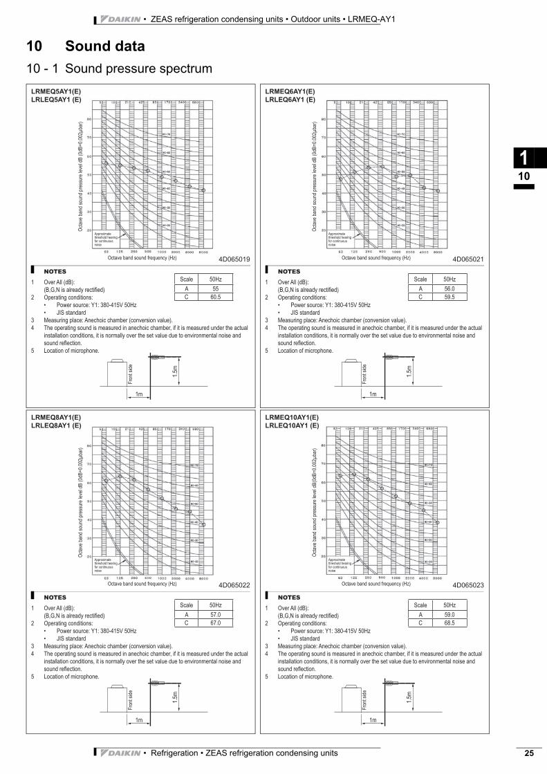
LRMEQ5AY1(E)
LRLEQ5AY1 (E)
4D065019
NOTES
1 Over All (dB):
(B,G,N is already rectifi ed)
2 Operating conditions:
Power source: Y1: 380-415V 50Hz
JIS standard
3 Measuring place: Anechoic chamber (conversion value).
4 The operating sound is measured in anechoic chamber, if it is measured under the actual
installation conditions, it is normally over the set value due to environmental noise and
sound refl ection.
5 Location of microphone.
•
•
Octa
ve
ba
nd
so
un
d p
ressu
re le
ve
l d
B (
0d
B=
0.0
02
ba
r)
Octave band sound frequency (Hz)
Approximate
threshold hearing
for continuous
noise
Fro
nt
sid
e
1m
1.5
m
Scale 50Hz
A 55
C 60.5
LRMEQ6AY1(E)
LRLEQ6AY1 (E)
4D065021
NOTES
1 Over All (dB):
(B,G,N is already rectifi ed)
2 Operating conditions:
Power source: Y1: 380-415V 50Hz
JIS standard
3 Measuring place: Anechoic chamber (conversion value).
4 The operating sound is measured in anechoic chamber, if it is measured under the actual
installation conditions, it is normally over the set value due to environmental noise and
sound refl ection.
5 Location of microphone.
•
•O
cta
ve
ba
nd
so
un
d p
ressu
re le
ve
l d
B (
0d
B=
0.0
02
ba
r)
Octave band sound frequency (Hz)
Approximate
threshold hearing
for continuous
noise
Fro
nt
sid
e
1m
1.5
m
Scale 50Hz
A 56.0
C 59.5
LRMEQ8AY1(E)
LRLEQ8AY1 (E)
4D065022
NOTES
1 Over All (dB):
(B,G,N is already rectifi ed)
2 Operating conditions:
Power source: Y1: 380-415V 50Hz
JIS standard
3 Measuring place: Anechoic chamber (conversion value).
4 The operating sound is measured in anechoic chamber, if it is measured under the actual
installation conditions, it is normally over the set value due to environmental noise and
sound refl ection.
5 Location of microphone.
•
•
Octa
ve
ba
nd
so
un
d p
ressu
re le
ve
l d
B (
0d
B=
0.0
02
ba
r)
Octave band sound frequency (Hz)
Approximate
threshold hearing
for continuous
noise
Fro
nt
sid
e
1m
1.5
m
Scale 50Hz
A 57.0
C 67.0
LRMEQ10AY1(E)
LRLEQ10AY1 (E)
4D065023
NOTES
1 Over All (dB):
(B,G,N is already rectifi ed)
2 Operating conditions:
Power source: Y1: 380-415V 50Hz
JIS standard
3 Measuring place: Anechoic chamber (conversion value).
4 The operating sound is measured in anechoic chamber, if it is measured under the actual
installation conditions, it is normally over the set value due to environmental noise and
sound refl ection.
5 Location of microphone.
•
•
Octa
ve
ba
nd
so
un
d p
ressu
re le
ve
l d
B(0
dB
=0
.00
2b
ar)
Octave band sound frequency (Hz)
Approximate
threshold hearing
for continuous
noise
Fro
nt
sid
e
1m
1.5
m
Scale 50Hz
A 59.0
C 68.5
• ZEAS refrigeration condensing units • Outdoor units • LRMEQ-AY1
• Refrigeration • ZEAS refrigeration condensing units26
10 Sound data
10 - 1 Sound pressure spectrum
110
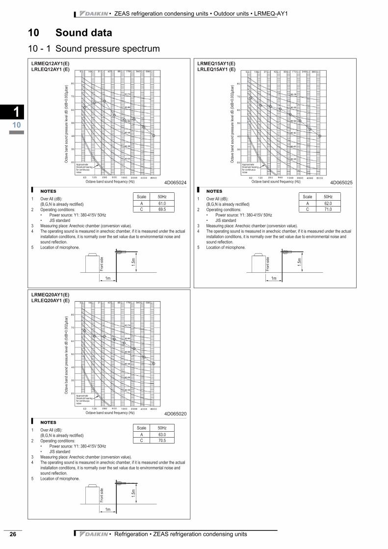
LRMEQ12AY1(E)
LRLEQ12AY1 (E)
4D065024
NOTES
1 Over All (dB):
(B,G,N is already rectifi ed)
2 Operating conditions:
Power source: Y1: 380-415V 50Hz
JIS standard
3 Measuring place: Anechoic chamber (conversion value).
4 The operating sound is measured in anechoic chamber, if it is measured under the actual
installation conditions, it is normally over the set value due to environmental noise and
sound refl ection.
5 Location of microphone.
•
•
Octa
ve
ba
nd
so
un
d p
ressu
re le
ve
l d
B (
0d
B=
0.0
02
ba
r)
Octave band sound frequency (Hz)
Approximate
threshold hearing
for continuous
noise
Fro
nt
sid
e
1m
1.5
m
Scale 50Hz
A 61.0
C 69.5
LRMEQ15AY1(E)
LRLEQ15AY1 (E)
4D065025
NOTES
1 Over All (dB):
(B,G,N is already rectifi ed)
2 Operating conditions:
Power source: Y1: 380-415V 50Hz
JIS standard
3 Measuring place: Anechoic chamber (conversion value).
4 The operating sound is measured in anechoic chamber, if it is measured under the actual
installation conditions, it is normally over the set value due to environmental noise and
sound refl ection.
5 Location of microphone.
•
•
Octa
ve
ba
nd
so
un
d p
ressu
re le
ve
l d
B (
0d
B=
0.0
02
ba
r)
Octave band sound frequency (Hz)
Approximate
threshold hearing
for continuous
noise
Fro
nt
sid
e
1m
1.5
m
Scale 50Hz
A 62.0
C 71.0
LRMEQ20AY1(E)
LRLEQ20AY1 (E)
4D065020
NOTES
1 Over All (dB):
(B,G,N is already rectifi ed)
2 Operating conditions:
Power source: Y1: 380-415V 50Hz
JIS standard
3 Measuring place: Anechoic chamber (conversion value).
4 The operating sound is measured in anechoic chamber, if it is measured under the actual
installation conditions, it is normally over the set value due to environmental noise and
sound refl ection.
5 Location of microphone.
•
•
Octa
ve
ba
nd
so
un
d p
ressu
re le
ve
l d
B (
0d
B=
0.0
02
ba
r)
Octave band sound frequency (Hz)
Approximate
threshold hearing
for continuous
noise
Fro
nt
sid
e
1m
1.5
m
Scale 50Hz
A 63.0
C 70.5
• Refrigeration • ZEAS refrigeration condensing units 27
• ZEAS refrigeration condensing units • Outdoor units • LRMEQ-AY1
11 Installation
11 - 1 Installation method
111
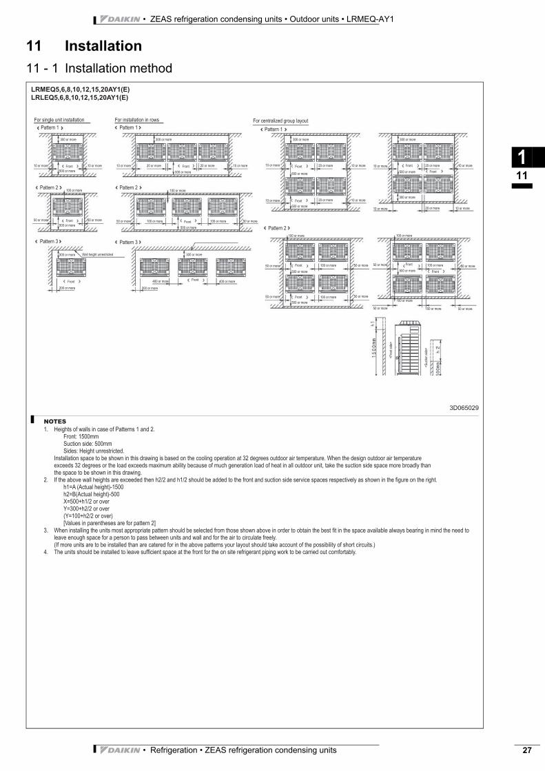
LRMEQ5,6,8,10,12,15,20AY1(E)
LRLEQ5,6,8,10,12,15,20AY1(E)
3D065029
NOTES
Heights of walls in case of Patterns 1 and 2.
Front: 1500mm
Suction side: 500mm
Sides: Height unrestricted.
Installation space to be shown in this drawing is based on the cooling operation at 32 degrees outdoor air temperature. When the design outdoor air temperature
exceeds 32 degrees or the load exceeds maximum ability because of much generation load of heat in all outdoor unit, take the suction side space more broadly than
the space to be shown in this drawing.
If the above wall heights are exceeded then h2/2 and h1/2 should be added to the front and suction side service spaces respectively as shown in the fi gure on the right.
h1=A (Actual height)-1500
h2=B(Actual height)-500
X=500+h1/2 or over
Y=300+h2/2 or over
(Y=100+h2/2 or over)
[Values in parentheses are for pattern 2]
When installing the units most appropriate pattern should be selected from those shown above in order to obtain the best fi t in the space available always bearing in mind the need to
leave enough space for a person to pass between units and wall and for the air to circulate freely.
(If more units are to be installed than are catered for in the above patterns your layout should take account of the possibility of short circuits.)
The units should be installed to leave suffi cient space at the front for the on site refrigerant piping work to be carried out comfortably.
1.
2.
3.
4.
For single unit installation For installation in rows For centralized group layout
Pattern 1 Pattern 1 Pattern 1
Pattern 2 Pattern 2
Pattern 2
Pattern 3 Pattern 3
300 or more
10 or more 10 or moreFront
500 or more
100 or more
50 or more 50 or moreFront
500 or more
Front
200 or more
300 or more Wall height unrestricted
300 or more
10 or more 20 or more
500 or more
20 or more 10 or moreFront
100 or more
50 or more 100 or more
500 or more
100 or more 50 or moreFront
200 or more
Front400 or more 400 or more
300 or more
300 or more
10 or more 20 or moreFront 10 or more
600 or more
10 or more 10 or more20 or moreFront
500 or more
100 or more
50 or more 100 or moreFront 50 or more
500 or more
50 or more 50 or more100 or moreFront
500 or more
300 or more
10 or more 20 or moreFront 10 or more
500 or more
10 or more 10 or more20 or more
300 or more
100 or more
50 or more 100 or moreFront50 or more
500 or more
50 or more 50 or more100 or more
100 or more
Front
Front
<F
ront sid
e>
<S
uction s
ide>
• ZEAS refrigeration condensing units • Outdoor units • LRMEQ-AY1
• Refrigeration • ZEAS refrigeration condensing units28
11 Installation
11 - 2 Fixation and foundation of units
111
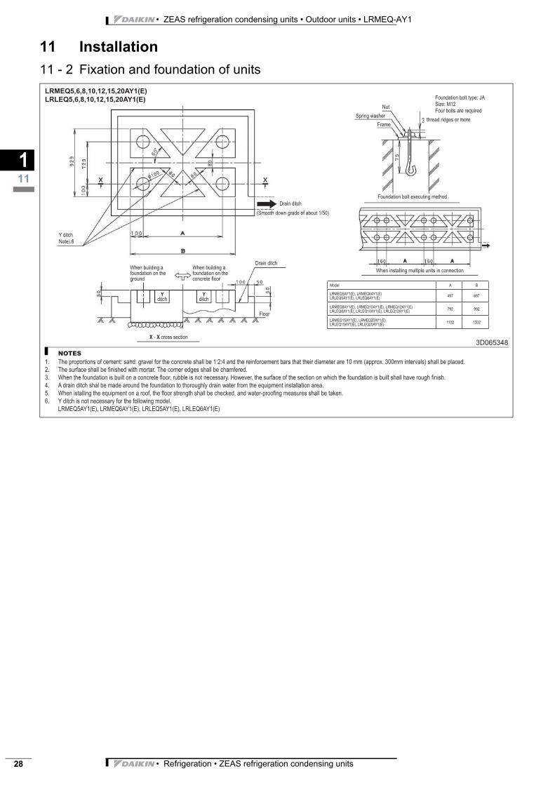
LRMEQ5,6,8,10,12,15,20AY1(E)
LRLEQ5,6,8,10,12,15,20AY1(E)
3D065348
NOTES
The proportions of cement: sand: gravel for the concrete shall be 1:2:4 and the reinforcement bars that their diameter are 10 mm (approx. 300mm intervals) shall be placed.
The surface shall be fi nished with mortar. The corner edges shall be chamfered.
When the foundation is built on a concrete fl oor, rubble is not necessary. However, the surface of the section on which the foundation is built shall have rough fi nish.
A drain ditch shal be made around the foundation to thoroughly drain water from the equipment installation area.
When istalling the equipment on a roof, the fl oor strength shall be checked, and water-proofi ng measures shall be taken.
Y ditch is not necessary for the following model.
LRMEQ5AY1(E), LRMEQ6AY1(E), LRLEQ5AY1(E), LRLEQ6AY1(E)
1.
2.
3.
4.
5.
6.
Y ditch
Note).6
Drain ditch
(Smooth down grade of about 1/50)
When building a
foundation on the
ground
When building a
foundation on the
concrete fl oor
Drain ditch
Floor
X - X cross section
Yditch
Yditch
Nut
Spring washer
Frame
Foundation bolt executing method
When installing multiple units in connection
Foundation bolt type: JA
Size: M12
Four bolts are required
thread ridges or more
Model A B
LRMEQ5AY1(E), LRMEQ6AY1(E)
LRLEQ5AY1(E), LRLEQ6AY1(E)497 697
LRMEQ8AY1(E), LRMEQ10AY1(E), LRMEQ12AY1(E)
LRLEQ8AY1(E), LRLEQ10AY1(E), LRLEQ12AY1(E)792 992
LRMEQ15AY1(E), LRMEQ20AY1(E)
LRLEQ15AY1(E), LRLEQ20AY1(E)1102 1302
• Refrigeration • ZEAS refrigeration condensing units 29
• ZEAS refrigeration condensing units • Outdoor units • LRMEQ-AY1
12 Operation range
112
LRMEQ5,6,8,10,12,15,20AY1
4D064918
NOTES
See operation limits and performance characteristics.
When the outside temp. is low, it lowers more than set temp. because of the unit protection.
Install the oil trap per 5m from outdoor unit.
1.
2.
3.
ITEM STANDARD FOR USE
Power
supply
Voltage fl uctuation Within ± 10% of rated voltage
Unbalanced load Within ± 2% of rated voltage
Frequency fl uctuation Within ± 2% of rated voltage
Outside temp. range -15 ~ 43 °C DB *1
Evaporating temp. range -20 ~ 10°C DB (less than RH95%) *2
Frequency ON/OFF of comp. Less than 6 times / hour
Time at pull down More than 3°C / hour
Maximum length of connection piping 130m
Maximum height difference between
indoor unit and outdoor units
10m (case that outdoor unit is lower than indoor unit)
35m (case that outdoor unit is higher than indoor unit) *3
Maximum refrigerant charge amount (See ADDITIONAL REFR. CHARGE LABEL about additional refrigerant)
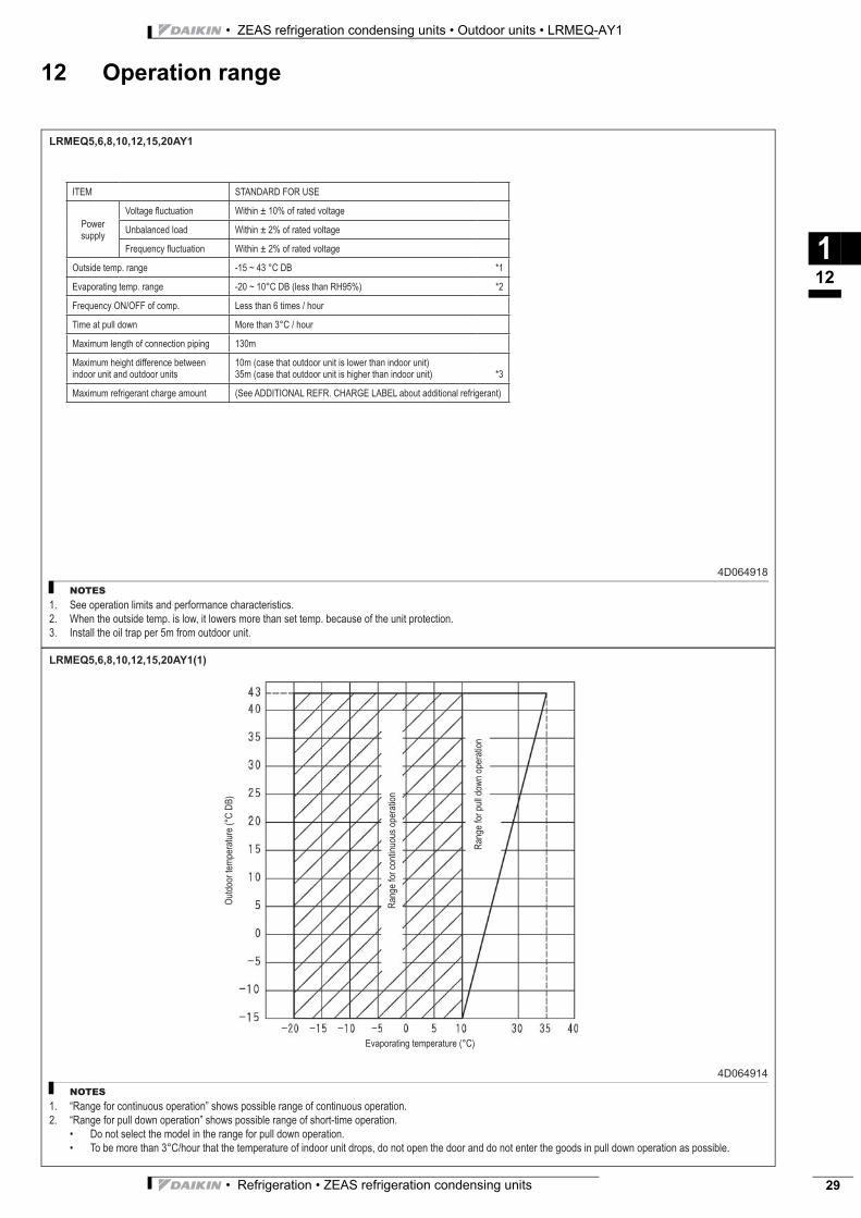
LRMEQ5,6,8,10,12,15,20AY1(1)
4D064914
NOTES
“Range for continuous operation” shows possible range of continuous operation.
“Range for pull down operation” shows possible range of short-time operation.
Do not select the model in the range for pull down operation.
To be more than 3°C/hour that the temperature of indoor unit drops, do not open the door and do not enter the goods in pull down operation as possible.
1.
2.
•
•
Outd
oor
tem
pera
ture
(°C
DB
)
Range for
continuous o
pera
tion
Range for
pull d
ow
n o
pera
tion
Evaporating temperature (°C)

• ZEAS refrigeration condensing units • Outdoor units • LRMEQ-AY1
• Refrigeration • ZEAS refrigeration condensing units30
12 Operation range
112

• Refrigeration • ZEAS refrigeration condensing units 31
• ZEAS refrigeration condensing units • Outdoor units • LRLEQ-AY1
TABLE OF CONTENTSLRLEQ-AY1
1 Features . . . . . . . . . . . . . . . . . . . . . . . . . . . . . . . . . . . . . . . . . . . . . . . . . . . . . . . . . . . . . 2
2 Specifications . . . . . . . . . . . . . . . . . . . . . . . . . . . . . . . . . . . . . . . . . . . . . . . . . . . . . . . 3
Electrical Specifications . . . . . . . . . . . . . . . . . . . . . . . . . . . . . . . . . . . . . . . . . . . . . . 3
Technical Specifications . . . . . . . . . . . . . . . . . . . . . . . . . . . . . . . . . . . . . . . . . . . . . 3
Electrical Specifications . . . . . . . . . . . . . . . . . . . . . . . . . . . . . . . . . . . . . . . . . . . . . . 4
3 Nomenclature . . . . . . . . . . . . . . . . . . . . . . . . . . . . . . . . . . . . . . . . . . . . . . . . . . . . . . . 5
4 Electrical data . . . . . . . . . . . . . . . . . . . . . . . . . . . . . . . . . . . . . . . . . . . . . . . . . . . . . . . 6
5 Options . . . . . . . . . . . . . . . . . . . . . . . . . . . . . . . . . . . . . . . . . . . . . . . . . . . . . . . . . . . . . . 7
6 Capacity tables . . . . . . . . . . . . . . . . . . . . . . . . . . . . . . . . . . . . . . . . . . . . . . . . . . . . . 8
Cooling capacity tables . . . . . . . . . . . . . . . . . . . . . . . . . . . . . . . . . . . . . . . . . . . . . . 8
7 Dimensional drawing & centre of gravity . . . . . . . . . . . . . . . . . . . . . . . 10
Dimensional drawing . . . . . . . . . . . . . . . . . . . . . . . . . . . . . . . . . . . . . . . . . . . . . . . . 10
Centre of gravity . . . . . . . . . . . . . . . . . . . . . . . . . . . . . . . . . . . . . . . . . . . . . . . . . . . . 14
8 Piping diagram. . . . . . . . . . . . . . . . . . . . . . . . . . . . . . . . . . . . . . . . . . . . . . . . . . . . . 16
9 Wiring diagram. . . . . . . . . . . . . . . . . . . . . . . . . . . . . . . . . . . . . . . . . . . . . . . . . . . . . 19
Wiring diagram . . . . . . . . . . . . . . . . . . . . . . . . . . . . . . . . . . . . . . . . . . . . . . . . . . . . . . 19
External connection diagram . . . . . . . . . . . . . . . . . . . . . . . . . . . . . . . . . . . . . . . . 22
10 Sound data . . . . . . . . . . . . . . . . . . . . . . . . . . . . . . . . . . . . . . . . . . . . . . . . . . . . . . . . . 23
Sound pressure spectrum . . . . . . . . . . . . . . . . . . . . . . . . . . . . . . . . . . . . . . . . . . . 23
11 Installation . . . . . . . . . . . . . . . . . . . . . . . . . . . . . . . . . . . . . . . . . . . . . . . . . . . . . . . . . . 25
Installation method . . . . . . . . . . . . . . . . . . . . . . . . . . . . . . . . . . . . . . . . . . . . . . . . . . 25
Fixation and foundation of units . . . . . . . . . . . . . . . . . . . . . . . . . . . . . . . . . . . . . 26
12 Operation range . . . . . . . . . . . . . . . . . . . . . . . . . . . . . . . . . . . . . . . . . . . . . . . . . . . 27
• ZEAS refrigeration condensing units • Outdoor units • LRLEQ-AY1
• Refrigeration • ZEAS refrigeration condensing units32
1 Features
21
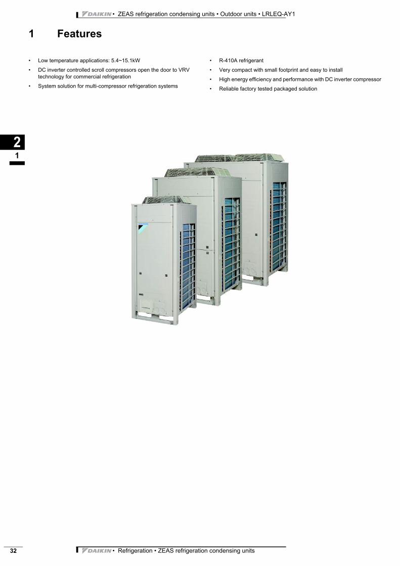
ZEAS refrig Refrigeratio LRLEQ-AY1 Outdoor uni • Low temperature applications: 5.4~15.1kW
• DC inverter controlled scroll compressors open the door to VRV technology for commercial refrigeration
• System solution for multi-compressor refrigeration systems
• R-410A refrigerant
• Very compact with small footprint and easy to install
• High energy efficiency and performance with DC inverter compressor
• Reliable factory tested packaged solution
• Refrigeration • ZEAS refrigeration condensing units 33
• ZEAS refrigeration condensing units • Outdoor units • LRLEQ-AY1
2 Specifications
22
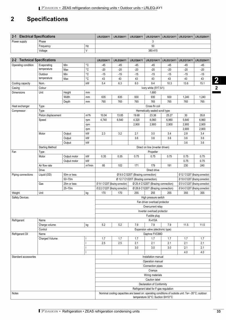
2-1 Electrical Specifications LRLEQ5AY1 LRLEQ6AY1 LRLEQ8AY1 LRLEQ10AY1 LRLEQ12AY1 LRLEQ15AY1 LRLEQ20AY1
Power supply Phase 3
Frequency Hz 50
Voltage V 380-415
2-2 Technical Specifications LRLEQ5AY1 LRLEQ6AY1 LRLEQ8AY1 LRLEQ10AY1 LRLEQ12AY1 LRLEQ15AY1 LRLEQ20AY1
Operating condition Evaporating temperature
Min °C -45 -45 -45 -45 -45 -45 -45
Max °C -20 -20 -20 -20 -20 -20 -20
Outdoor temperature
Min °C -15 -15 -15 -15 -15 -15 -15
Max °C 43 43 43 43 43 43 43
Cooling capacity Nom. kW 5.4 6.3 8.0 9.4 10.3 13.6 15.1
Casing Colour Ivory white (5Y7,5/1)
Dimensions Unit Height mm 1,680
Width mm 635 635 930 930 930 1,240 1,240
Depth mm 765 765 765 765 765 765 765
Heat exchanger Type Cross fin coil
Compressor Type Hermetically sealed scroll type
Piston displacement m³/h 10.04 13.85 19.68 23.36 25.27 30 35.8
Speed rpm 4,740 6,540 4,320 6,060 6,960 5,640 6,960
rpm 2,900 2,900 2,900 2,900 2,900
rpm 2,900 2,900
Motor Output kW 2.3 3.2 2.1 3.0 3.4 2.8 3.4
Output kW 3.6 3.6 3.6 3.6 3.6
Output kW 3.6 3.6
Starting Method Direct on line (inverter driven)
Fan Type Propeller
Motor Output motor kW 0.35 0.35 0.75 0.75 0.75 0.75 0.75
Output motor kW 0.75 0.75
Air flow rate m³/min 95 102 171 179 191 230 240
Drive Direct drive
Piping connections Liquid (OD) 50m or less Ø 9.5 C1220T (Brazing connection) Ø 12.7 C1220T (Brazing connection)
50~70m Ø 12.7 C1220T (Brazing connection) Ø 15.9 C1220T (Brazing connection)
Gas 25m or less Ø 19.1 C1220T (Brazing connection) Ø 25.4 C1220T (Brazing connection) Ø 31.8 C1220T (Brazing connection)
25~70m Ø 22.2 C1220T (Brazing connection) Ø 28.6 C1220T (Brazing connection) Ø 34.9 C1220T (Brazing connection)
Weight Unit kg 170 170 255 255 255 355 355
Safety Devices High pressure switch
Fan driver overload protector
Overcurrent relay
Inverter overload protector
Fusible plug
Refrigerant Name R-410A
Charge volume kg 5.2 5.2 7.9 7.9 7.9 11.5 11.5
Control Expansion valve (electronic type)
Refrigerant Oil Name Daphne FVC68D
Charged Volume l 1.7 1.7 1.7 1.7 1.7 1.7 1.7
l 2.5 2.5 2.1 2.1 2.1 2.1 2.1
l 3.0 3.0 3.0 2.1 2.1
l 4.0 4.0
Standard accessories Installation manual
Operation manual
Connection pipes
Cramps
Wiring materials
Caution label
Declaration of Conformity
Refrigerant label for F-gas regulation
Notes Nominal cooling capacities are based on: operating conditions of outside unit: Te= -35°C; outdoor temperature 32°C; Suction SH10°C
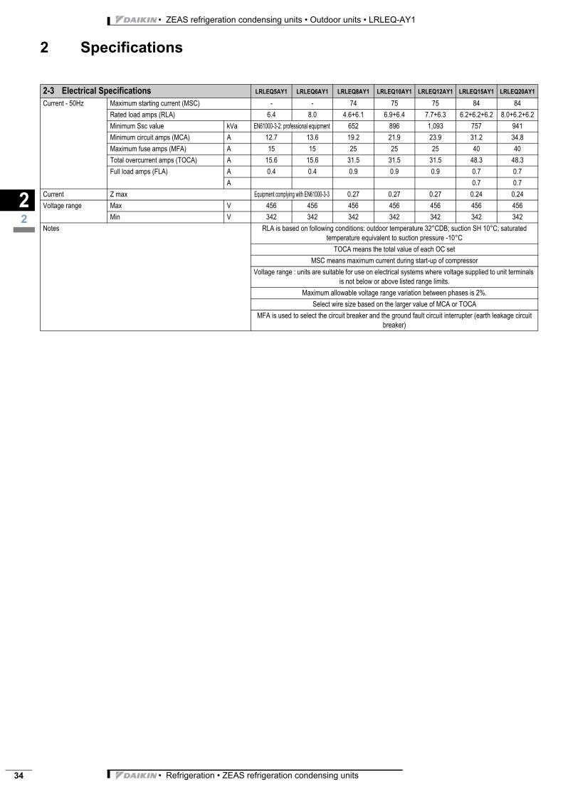
• ZEAS refrigeration condensing units • Outdoor units • LRLEQ-AY1
• Refrigeration • ZEAS refrigeration condensing units34
2 Specifications
22
2-3 Electrical Specifications LRLEQ5AY1 LRLEQ6AY1 LRLEQ8AY1 LRLEQ10AY1 LRLEQ12AY1 LRLEQ15AY1 LRLEQ20AY1
Current - 50Hz Maximum starting current (MSC) - - 74 75 75 84 84
Rated load amps (RLA) 6.4 8.0 4.6+6.1 6.9+6.4 7.7+6.3 6.2+6.2+6.2 8.0+6.2+6.2
Minimum Ssc value kVa EN61000-3-2: professional equipment 652 896 1,093 757 941
Minimum circuit amps (MCA) A 12.7 13.6 19.2 21.9 23.9 31.2 34.8
Maximum fuse amps (MFA) A 15 15 25 25 25 40 40
Total overcurrent amps (TOCA) A 15.6 15.6 31.5 31.5 31.5 48.3 48.3
Full load amps (FLA) A 0.4 0.4 0.9 0.9 0.9 0.7 0.7
A 0.7 0.7
Current Z max Equipment complying with EN61000-3-3 0.27 0.27 0.27 0.24 0.24
Voltage range Max V 456 456 456 456 456 456 456
Min V 342 342 342 342 342 342 342
Notes RLA is based on following conditions: outdoor temperature 32°CDB; suction SH 10°C; saturated temperature equivalent to suction pressure -10°C
TOCA means the total value of each OC set
MSC means maximum current during start-up of compressor
Voltage range : units are suitable for use on electrical systems where voltage supplied to unit terminals is not below or above listed range limits.
Maximum allowable voltage range variation between phases is 2%.
Select wire size based on the larger value of MCA or TOCA
MFA is used to select the circuit breaker and the ground fault circuit interrupter (earth leakage circuit breaker)
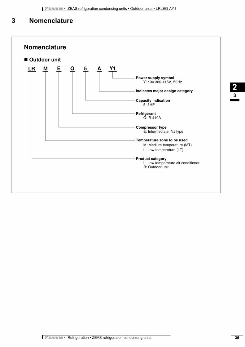
• Refrigeration • ZEAS refrigeration condensing units 35
• ZEAS refrigeration condensing units • Outdoor units • LRLEQ-AY1
3 Nomenclature
23
Nomenclature
� Outdoor unit
LR M E Q 5 A Y1
Power supply symbolY1: 3φ 380-415V, 50Hz
Indicates major design category
Capacity indication5: 5HP
RefrigerantQ: R-410A
Compressor typeE: Intermediate INJ type
Temperature zone to be usedM: Medium temperature (MT)L: Low temperature (LT)
Product categoryL: Low temperature air conditionerR: Outdoor unit
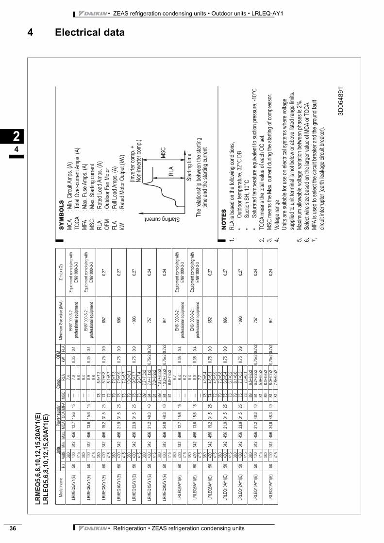
• ZEAS refrigeration condensing units • Outdoor units • LRLEQ-AY1
• Refrigeration • ZEAS refrigeration condensing units36
4 Electrical data
24
3D
06
48
91
NO
TE
S
RLA
is b
ased o
n the follo
win
g c
onditio
ns,
Outd
oor
tem
pera
ture
, 32°C
DB
Suction S
H, 10°C
Satu
rate
d tem
pera
ture
equiv
ale
nt to
suction p
ressure
, -1
0°C
TO
CA
means the tota
l valu
e o
f each O
C s
et.
MS
C m
eans the M
ax. curr
ent during the s
tart
ing o
f com
pre
ssor.
Voltage r
ange
Units a
re s
uitable
for
use o
n e
lectr
ical syste
ms w
here
voltage
supplie
d to u
nit term
inal is
not belo
w o
r above lis
ted r
ange lim
its.
Maxim
um
allo
wable
voltage v
ariation b
etw
een p
hases is 2
%.
Sele
ct w
ire s
ize b
ased o
n the larg
er
valu
e o
f M
CA
or
TO
CA
.
MF
A is u
sed to s
ele
ct th
e c
ircuit b
reaker
and the g
round fault
circuit inte
rrupte
r (e
art
h leakage c
ircuit b
reaker)
.
1.
• • •
2.
3.
4.
5.
6.
7.
LR
ME
Q5
,6,8
,10
,12
,15
,20
AY
1(E
)
LR
LE
Q5
,6,8
,10
,12
,15
,20
AY
1(E
)
Model nam
eU
nits
Pow
er
supply
Com
p.
OF
MM
inim
um
Ssc v
alu
e (
kV
A)
Z m
ax (
)H
zV
olts
Min
.M
ax.
MC
AT
OC
AM
FA
MS
CR
LA
kW
FLA
LR
ME
Q5A
Y1(E
)50
380
342
456
12.7
15.6
15
—7.4
0.3
50.4
EN
61000-3
-2:
pro
fessio
nal equip
ment
Equip
ment com
ply
ing w
ith
EN
61000-3
-3400
—7.0
415
—6.8
LR
ME
Q6A
Y1(E
)50
380
342
456
13.6
15.6
15
—9.4
0.3
50.4
EN
61000-3
-2:
pro
fessio
nal equip
ment
Equip
ment com
ply
ing w
ith
EN
61000-3
-3400
—8.9
415
—8.6
LR
ME
Q8A
Y1(E
)50
380
342
456
19.2
31.5
25
78
5.5
+7.2
0.7
50.9
652
0.2
7400
74
5.2
+6.8
415
72
5.1
+6.7
LR
ME
Q10A
Y1(E
)50
380
342
456
21.9
31.5
25
79
7.9
+7.3
0.7
50.9
896
0.2
7400
75
7.5
+6.9
415
73
7.3
+6.7
LR
ME
Q12A
Y1(E
)50
380
342
456
23.9
31.5
25
79
10.0
+8.1
0.7
50.9
1093
0.2
7400
75
9.5
+7.7
415
73
9.3
+7.4
LR
ME
Q15A
Y1(E
)50
380
342
456
31.2
48.3
40
89
7.7
+7.5
x2
0.7
5x2
0.7
x2
757
0.2
4400
84
7.4
+7.1
x2
415
81
7.0
+6.9
x2
LR
ME
Q20A
Y1(E
)50
380
342
456
34.8
48.3
40
89
10.7
+8.3
x2
0.7
5x2
0.7
x2
941
0.2
4400
84
10.2
+7.8
x2
415
81
9.8
+7.6
x2
LR
LE
Q5A
Y1(E
)50
380
342
456
12.7
15.6
15
—6.7
0.3
50.4
EN
61000-3
-2:
pro
fessio
nal equip
ment
Equip
ment com
ply
ing w
ith
EN
61000-3
-3400
—6.4
415
—6.2
LR
LE
Q6A
Y1(E
)50
380
342
456
13.6
15.6
15
—8.4
0.3
50.4
EN
61000-3
-2:
pro
fessio
nal equip
ment
Equip
ment com
ply
ing w
ith
EN
61000-3
-3400
—8.0
415
—7.7
LR
LE
Q8A
Y1(E
)50
380
342
456
19.2
31.5
25
78
4.9
+6.4
0.7
50.9
652
0.2
7400
74
4.6
+6.1
415
72
4.5
+5.9
LR
LE
Q10A
Y1(E
)50
380
342
456
21.9
31.5
25
79
7.2
+6.8
0.7
50.9
896
0.2
7400
75
6.9
+6.4
415
73
6.7
+6.2
LR
LE
Q12A
Y1(E
)50
380
342
456
23.9
31.5
25
79
8.1
+6.6
0.7
50.9
1093
0.2
7400
75
7.7
+6.3
415
73
7.5
+6.1
LR
LE
Q15A
Y1(E
)50
380
342
456
31.2
48.3
40
89
6.5
+6.6
x2
0.7
5x2
0.7
x2
757
0.2
4400
84
6.2
+6.2
x2
415
81
5.9
+6.0
x2
LR
LE
Q20A
Y1(E
)50
380
342
456
34.8
48.3
40
89
8.3
+6.6
x2
0.7
5x2
0.7
x2
941
0.2
4400
84
8.0
+6.2
x2
415
81
7.6
+6.0
x2
SY
MB
OL
S
MC
A
: M
in. C
ircuit A
mps. (A
)
TO
CA
: Tota
l O
ver-
curr
ent A
mps. (A
)
MF
A
: M
ax. F
use A
mps. (A
)
MS
C
: M
ax. S
tart
ing c
urr
ent
RLA
: R
ate
d L
oad A
mps. (A
)
OF
M
: O
utd
oor
Fan M
oto
r
FLA
: F
ull
Load A
mps. (A
)
kW
: R
ate
d M
oto
r O
utp
ut (k
W)
(Invert
er
com
p. +
Non-invert
er
com
p.)
The r
ela
tionship
betw
een the s
tart
ing
tim
e a
nd the s
tart
ing c
urr
ent
Sta
rtin
g tim
e
Starting current
RLA
MS
C
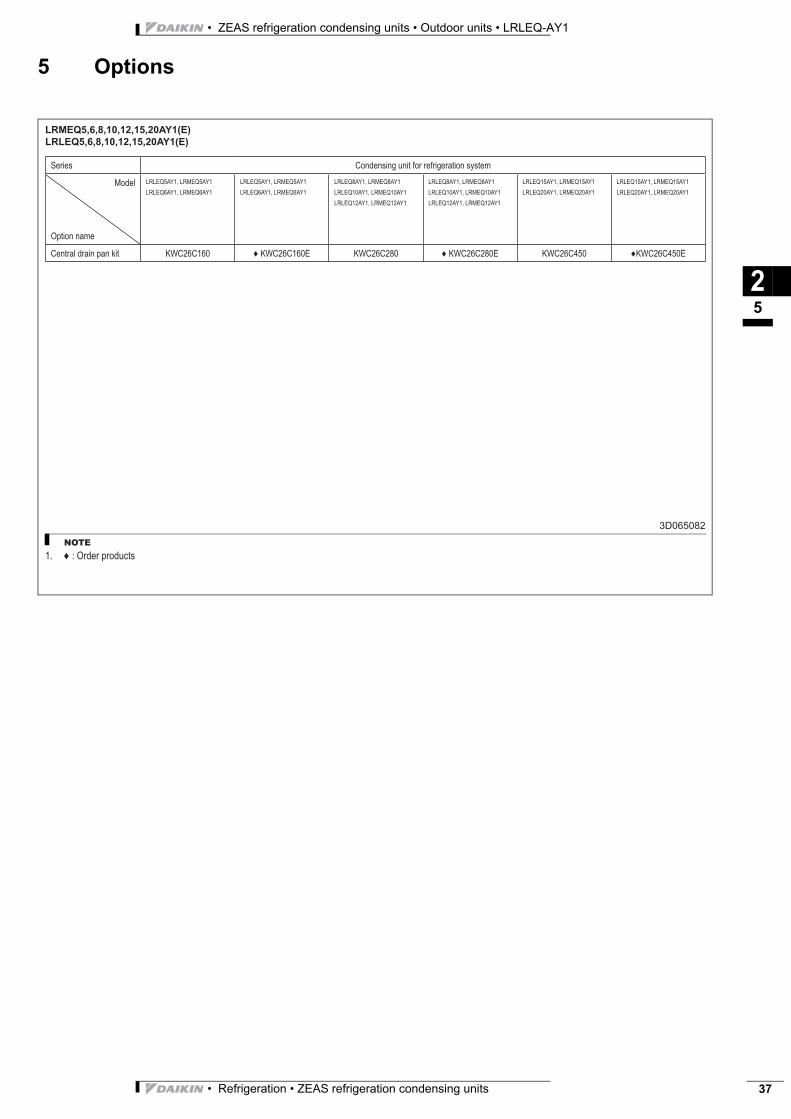
• Refrigeration • ZEAS refrigeration condensing units 37
• ZEAS refrigeration condensing units • Outdoor units • LRLEQ-AY1
5 Options
25
LRMEQ5,6,8,10,12,15,20AY1(E)
LRLEQ5,6,8,10,12,15,20AY1(E)
3D065082
NOTE
: Order products1.
Series Condensing unit for refrigeration system
Model
Option name
LRLEQ5AY1, LRMEQ5AY1
LRLEQ6AY1, LRMEQ6AY1
LRLEQ5AY1, LRMEQ5AY1
LRLEQ6AY1, LRMEQ6AY1
LRLEQ8AY1, LRMEQ8AY1
LRLEQ10AY1, LRMEQ10AY1
LRLEQ12AY1, LRMEQ12AY1
LRLEQ8AY1, LRMEQ8AY1
LRLEQ10AY1, LRMEQ10AY1
LRLEQ12AY1, LRMEQ12AY1
LRLEQ15AY1, LRMEQ15AY1
LRLEQ20AY1, LRMEQ20AY1
LRLEQ15AY1, LRMEQ15AY1
LRLEQ20AY1, LRMEQ20AY1
Central drain pan kit KWC26C160 KWC26C160E KWC26C280 KWC26C280E KWC26C450 KWC26C450E
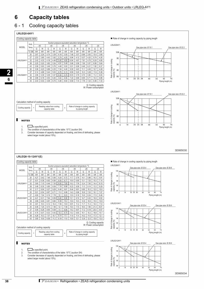
• ZEAS refrigeration condensing units • Outdoor units • LRLEQ-AY1
• Refrigeration • ZEAS refrigeration condensing units38
6 Capacity tables
6 - 1 Cooling capacity tables
26
LRLEQ5-6AY1
3D065030
NOTES
is specifi ed point.
The condition of characteristics of the table: 10°C (suction SH)
Consider decrease of capacity depended on frosting, and time of defrosting, please
select larger model (about 15%).
1.
2.
3.
MODEL
Amb.
Temp.
Suction pressure equivalent saturation temperature °C
-45 -40 -35 -30 -25 -20
Q W Q W Q W Q W Q W Q W
°C DB kW kW kW kW kW kW kW kW kW kW kW kW
LRLEQ5AY1
20 2.67 3.24 4.74 3.39 6.18 3.50 7.46 3.57 8.96 3.63 10.4 3.66
27 2.53 3.80 4.43 3.92 5.74 4.05 6.94 4.12 8.37 4.20 9.74 4.26
32 2.42 4.33 4.18 4.46 5.40 4.60 6.54 4.67 7.91 4.75 9.24 4.85
38 2.25 5.20 3.82 5.34 4.91 5.49 5.96 5.58 7.06 5.57 8.56 5.64
43 2.08 5.63 3.49 5.76 4.48 5.93 5.51 6.06 6.46 6.21 7.82 6.37
LRLEQ6AY1
20 3.36 4.23 5.89 4.33 7.34 4.40 9.30 4.43 11.1 4.45 12.7 4.49
27 3.14 4.88 5.44 5.03 6.76 5.13 8.59 5.20 10.3 5.28 11.9 5.38
32 2.96 5.39 5.08 5.57 6.30 5.70 8.03 5.79 9.70 5.90 11.2 6.05
38 2.68 6.18 4.53 6.40 5.62 6.56 7.22 6.69 8.55 6.71 10.3 6.86
43 2.43 6.53 4.08 6.75 5.06 6.93 6.59 7.14 7.76 7.23 9.36 7.33
Rate of change in cooling capacity by piping length
LRLEQ5AY1
Gas pipe size: Ø 19.1 Gas pipe size: Ø 22.2
LRLEQ6AY1
Gas pipe size: Ø 19.1 Gas pipe size: Ø 22.2
Q: Cooling capacity
W: Power consumption
Calculation method of cooling capacity
Cooling capacity =Reading value from cooling
capacity tablex
Rate of change in cooling capacity
by piping length
Ra
te o
f ch
an
ge
in
co
olin
g
ca
pa
city (
%)
Ra
te o
f ch
an
ge
in
co
olin
g
ca
pa
city (
%)
Piping length (m)
Piping length (m)
Cooling capacity table
LRLEQ8-10-12AY1(E)
3D065034
NOTES
is specifi ed point.
The condition of characteristics of the table: 10°C (suction SH)
Consider decrease of capacity depended on frosting, and time of defrosting, please
select larger model (about 15%).
1.
2.
3.
MODEL
Amb.
Temp.
Suction pressure equivalent saturation temperature °C
-45 -40 -35 -30 -25 -20
Q W Q W Q W Q W Q W Q W
°C DB kW kW kW kW kW kW kW kW kW kW kW kW
LRLEQ8AY1
20 4.27 5.42 7.46 5.56 9.24 5.72 11.7 5.79 14.1 5.86 16.3 5.91
27 4.01 6.38 6.92 6.56 8.55 6.77 10.9 6.90 13.1 7.03 15.3 7.14
32 3.80 7.15 6.49 7.35 8.00 7.60 10.2 7.76 12.4 7.93 14.4 8.10
38 3.48 8.35 5.85 8.59 7.19 8.88 9.23 9.09 11.0 9.14 13.3 9.29
43 3.17 9.04 5.27 9.29 6.48 9.61 8.44 9.91 9.95 10.3 12.0 10.6
LRLEQ10AY1
20 5.01 6.54 8.87 6.71 11.0 6.88 14.0 6.96 16.8 7.03 19.1 7.07
27 4.69 7.54 8.19 7.78 10.1 8.03 12.9 8.18 15.6 8.34 17.9 8.46
32 4.41 8.31 7.64 8.59 9.40 8.90 12.1 9.10 14.7 9.32 16.9 9.52
38 3.99 9.49 6.81 9.84 8.39 10.2 10.9 10.5 12.9 10.6 15.5 10.8
43 3.61 10.0 6.12 10.4 7.54 10.8 9.91 11.2 11.7 11.4 14.0 11.8
LRLEQ12AY1
20 5.46 7.25 9.73 7.46 12.1 7.59 15.4 7.72 18.5 7.85 21.4 8.01
27 5.08 8.28 8.95 8.58 11.1 8.80 14.2 8.97 17.2 9.18 20.0 9.57
32 4.76 9.07 8.32 9.42 10.3 9.70 13.2 9.93 16.1 10.2 18.8 10.7
38 4.28 10.3 7.37 10.7 9.14 11.1 11.9 11.4 14.2 11.6 17.3 12.1
43 3.85 10.8 6.59 11.2 8.18 11.6 10.8 12.1 12.8 12.5 15.6 13.0
Rate of change in cooling capacity by piping length
LRLEQ8AY1
Gas pipe size: Ø 25.4 Gas pipe size: Ø 28.6
LRLEQ10AY1
Gas pipe size: Ø 25.4 Gas pipe size: Ø 28.6
Q: Cooling capacity
W: Power consumption
Calculation method of cooling capacity
Cooling capacity =Reading value from cooling
capacity tablex
Rate of change in cooling capacity
by piping length
Ra
te o
f ch
an
ge
in
co
olin
g
ca
pa
city (
%)
Ra
te o
f ch
an
ge
in
co
olin
g
ca
pa
city (
%)
LRLEQ12AY1
Gas pipe size: Ø 25.4 Gas pipe size: Ø 28.6
Ra
te o
f ch
an
ge
in
co
olin
g
ca
pa
city (
%)
Piping length (m)
Piping length (m)
Piping length (m)
Cooling capacity table
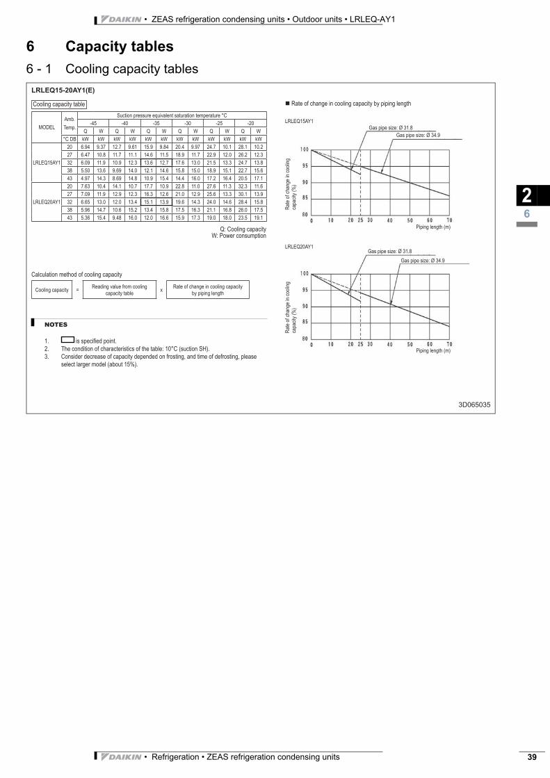
• Refrigeration • ZEAS refrigeration condensing units 39
• ZEAS refrigeration condensing units • Outdoor units • LRLEQ-AY1
6 Capacity tables
6 - 1 Cooling capacity tables
26
LRLEQ15-20AY1(E)
3D065035
NOTES
is specifi ed point.
The condition of characteristics of the table: 10°C (suction SH).
Consider decrease of capacity depended on frosting, and time of defrosting, please
select larger model (about 15%).
1.
2.
3.
MODEL
Amb.
Temp.
Suction pressure equivalent saturation temperature °C
-45 -40 -35 -30 -25 -20
Q W Q W Q W Q W Q W Q W
°C DB kW kW kW kW kW kW kW kW kW kW kW kW
LRLEQ15AY1
20 6.94 9.37 12.7 9.61 15.9 9.84 20.4 9.97 24.7 10.1 28.1 10.2
27 6.47 10.8 11.7 11.1 14.6 11.5 18.9 11.7 22.9 12.0 26.2 12.3
32 6.09 11.9 10.9 12.3 13.6 12.7 17.6 13.0 21.5 13.3 24.7 13.8
38 5.50 13.6 9.69 14.0 12.1 14.6 15.8 15.0 18.9 15.1 22.7 15.6
43 4.97 14.3 8.69 14.8 10.9 15.4 14.4 16.0 17.2 16.4 20.5 17.1
LRLEQ20AY1
20 7.63 10.4 14.1 10.7 17.7 10.9 22.8 11.0 27.6 11.3 32.3 11.6
27 7.09 11.9 12.9 12.3 16.3 12.6 21.0 12.9 25.6 13.3 30.1 13.9
32 6.65 13.0 12.0 13.4 15.1 13.9 19.6 14.3 24.0 14.6 28.4 15.8
38 5.96 14.7 10.6 15.2 13.4 15.8 17.5 16.3 21.1 16.8 26.0 17.5
43 5.36 15.4 9.48 16.0 12.0 16.6 15.9 17.3 19.0 18.0 23.5 19.1
Rate of change in cooling capacity by piping length
LRLEQ15AY1
Gas pipe size: Ø 31.8
Gas pipe size: Ø 34.9
LRLEQ20AY1Gas pipe size: Ø 31.8
Gas pipe size: Ø 34.9
Q: Cooling capacity
W: Power consumption
Calculation method of cooling capacity
Cooling capacity =Reading value from cooling
capacity tablex
Rate of change in cooling capacity
by piping length
Ra
te o
f ch
an
ge
in
co
olin
g
ca
pa
city (
%)
Ra
te o
f ch
an
ge
in
co
olin
g
ca
pa
city (
%)
Piping length (m)
Piping length (m)
Cooling capacity table
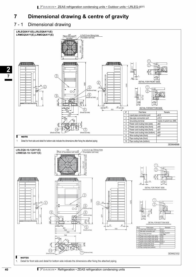
• ZEAS refrigeration condensing units • Outdoor units • LRLEQ-AY1
• Refrigeration • ZEAS refrigeration condensing units40
7 Dimensional drawing & centre of gravity
7 - 1 Dimensional drawing
27
3D064898
N° Parts Name Remarks
1 Liquid pipe connection port ø9,5
2 Gas pipe connection port ø19.1
3 Grounding terminal Inside of switch box (M8)
4 Power cord routing hole (side) ø62
5 Power cord routing hole (front) ø45
6 Power cord routing hole (front) ø27
7 Power cord routing hole (bottom) ø50
8 Wire routing hole (front) ø27
9 Pipe routing hole (front)
10 Pipe routing hole (bottom)
NOTE
1 Detail for front side and detail for bottom side indicate the dimensions after fixing the attached piping
(Pitch of foundation bolt holes)
4-15x22,5-mm-Oblong holes
(Foundation bolt hole)
(Pitch o
f fo
un
da
tion b
olt h
ole
s)
(Knock-out hole)
(Knock-out hole)
(Knock-out hole)
(Knock-out hole)(Knock-out hole)
DETAIL FOR FRONT SIDE
DETAIL FOR BOTTOM SIDE
LRLEQ5AY1(E),LRLEQ6AY1(E)
LRMEQ5AY1(E),LRMEQ6AY1(E)
LRLEQ8-10-12AY1(E)
LRMEQ8-10-12AY1(E)
3D062332
NOTES
Detail for front side and detail for bottom side indicate the dimensions after fi xing the attached piping.1.
No. Parts name Remarks
1 Liquid pipe connection port Ø 9.5
2 Gas pipe connection port Ø 25.4
3 Grounding terminalInside of switch box (M8)
4 Power cord routing hole (side) Ø 62
5 Power cord routing hole (front) Ø 45
6 Power cord routing hole (front) Ø 27
7 Power cord routing hole (bottom) Ø 65.5
8 Wire routing hole (front) Ø 27
9 Pipe routing hole (front)
10 Pipe routing hole (bottom)
Oblong holes
(Foundation bolt hole)
(Pitch
of
fou
nd
atio
n b
olt h
ole
)
(Pitch of foundation bolt hole)
(Knock-out hole)
(Knock-out hole)
(Knock-out hole)
(Knock-out hole)(Knock-out hole)
DETAIL FOR FRONT SIDE
DETAIL FOR BOTTOM SIDE
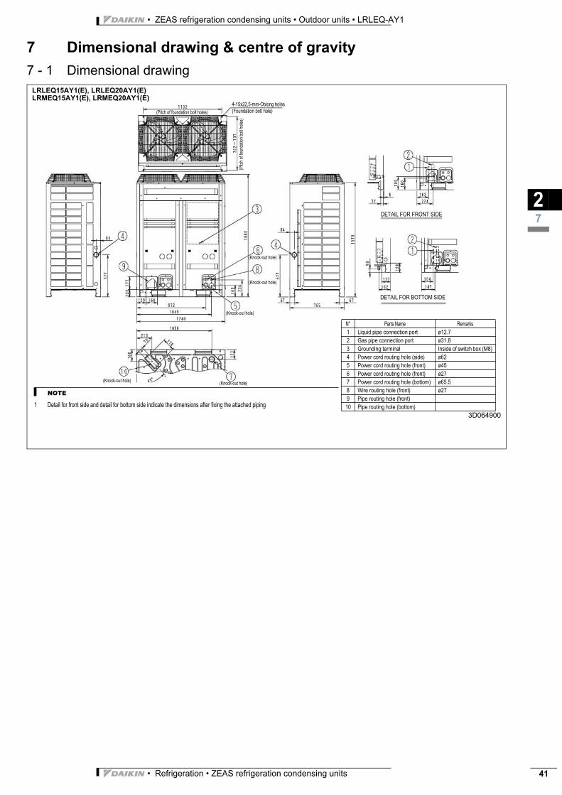
• Refrigeration • ZEAS refrigeration condensing units 41
• ZEAS refrigeration condensing units • Outdoor units • LRLEQ-AY1
7 Dimensional drawing & centre of gravity
7 - 1 Dimensional drawing
27
LRLEQ15AY1(E), LRLEQ20AY1(E)
LRMEQ15AY1(E), LRMEQ20AY1(E)
3D064900
N° Parts Name Remarks
1 Liquid pipe connection port ø12.7
2 Gas pipe connection port ø31.8
3 Grounding terminal Inside of switch box (M8)
4 Power cord routing hole (side) ø62
5 Power cord routing hole (front) ø45
6 Power cord routing hole (front) ø27
7 Power cord routing hole (bottom) ø65.5
8 Wire routing hole (front) ø27
9 Pipe routing hole (front)
10 Pipe routing hole (bottom)
NOTE
1 Detail for front side and detail for bottom side indicate the dimensions after fixing the attached piping
(Pitch of foundation bolt holes)
(Pitch o
f fo
un
da
tion b
olt h
ole
s)
(Knock-out hole)
(Knock-out hole)
(Knock-out hole)
(Knock-out hole)(Knock-out hole)
DETAIL FOR FRONT SIDE
DETAIL FOR BOTTOM SIDE
4-15x22,5-mm-Oblong holes
(Foundation bolt hole)
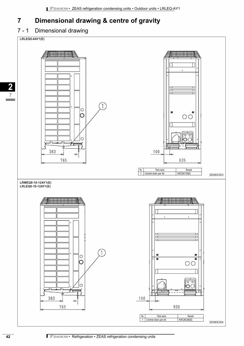
• ZEAS refrigeration condensing units • Outdoor units • LRLEQ-AY1
• Refrigeration • ZEAS refrigeration condensing units42
7 Dimensional drawing & centre of gravity
7 - 1 Dimensional drawing
27
( )
LRLEQ5-6AY1(E)
3D065353
No. Parts name Remark
1 Central drain pan kit KWC26C160(E)
LRMEQ8-10-12AY1(E)
LRLEQ8-10-12AY1(E)
3D065354
No. Parts name Remark
1 Central drain pan kit KWC26C280(E)
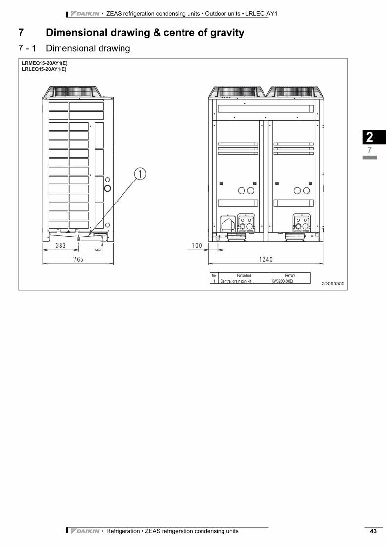
• Refrigeration • ZEAS refrigeration condensing units 43
• ZEAS refrigeration condensing units • Outdoor units • LRLEQ-AY1
7 Dimensional drawing & centre of gravity
7 - 1 Dimensional drawing
27
LRMEQ15-20AY1(E)
LRLEQ15-20AY1(E)
3D065355
No. Parts name Remark
1 Central drain pan kit KWC26C450(E)
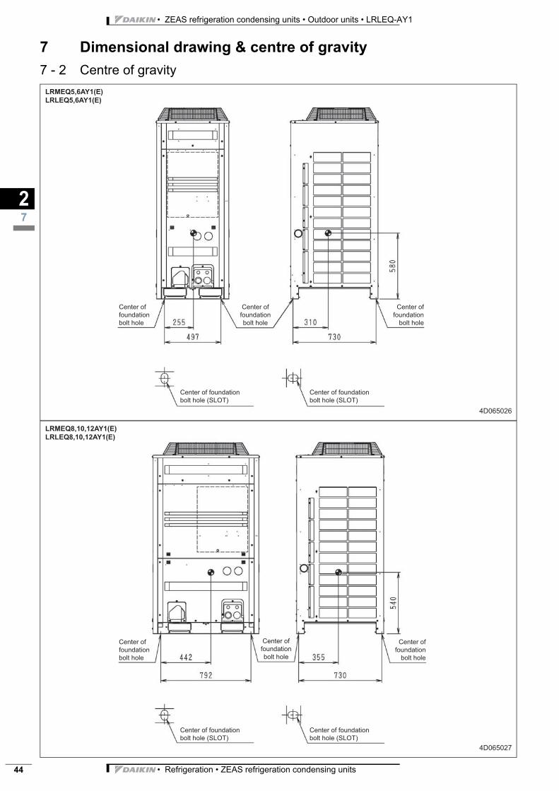
• ZEAS refrigeration condensing units • Outdoor units • LRLEQ-AY1
• Refrigeration • ZEAS refrigeration condensing units44
7 Dimensional drawing & centre of gravity
7 - 2 Centre of gravity
27
LRMEQ5,6AY1(E)
LRLEQ5,6AY1(E)
4D065026
Center of
foundation
bolt hole
Center of
foundation
bolt hole
Center of
foundation
bolt hole
Center of foundation
bolt hole (SLOT)
Center of foundation
bolt hole (SLOT)
LRMEQ8,10,12AY1(E)
LRLEQ8,10,12AY1(E)
4D065027
Center of
foundation
bolt hole
Center of
foundation
bolt hole
Center of
foundation
bolt hole
Center of foundation
bolt hole (SLOT)
Center of foundation
bolt hole (SLOT)
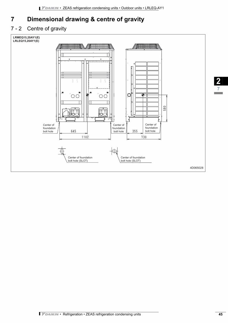
• Refrigeration • ZEAS refrigeration condensing units 45
• ZEAS refrigeration condensing units • Outdoor units • LRLEQ-AY1
7 Dimensional drawing & centre of gravity
7 - 2 Centre of gravity
27
LRMEQ15,20AY1(E)
LRLEQ15,20AY1(E)
4D065028
Center of
foundation
bolt hole
Center of
foundation
bolt hole
Center of
foundation
bolt hole
Center of foundation
bolt hole (SLOT)
Center of foundation
bolt hole (SLOT)
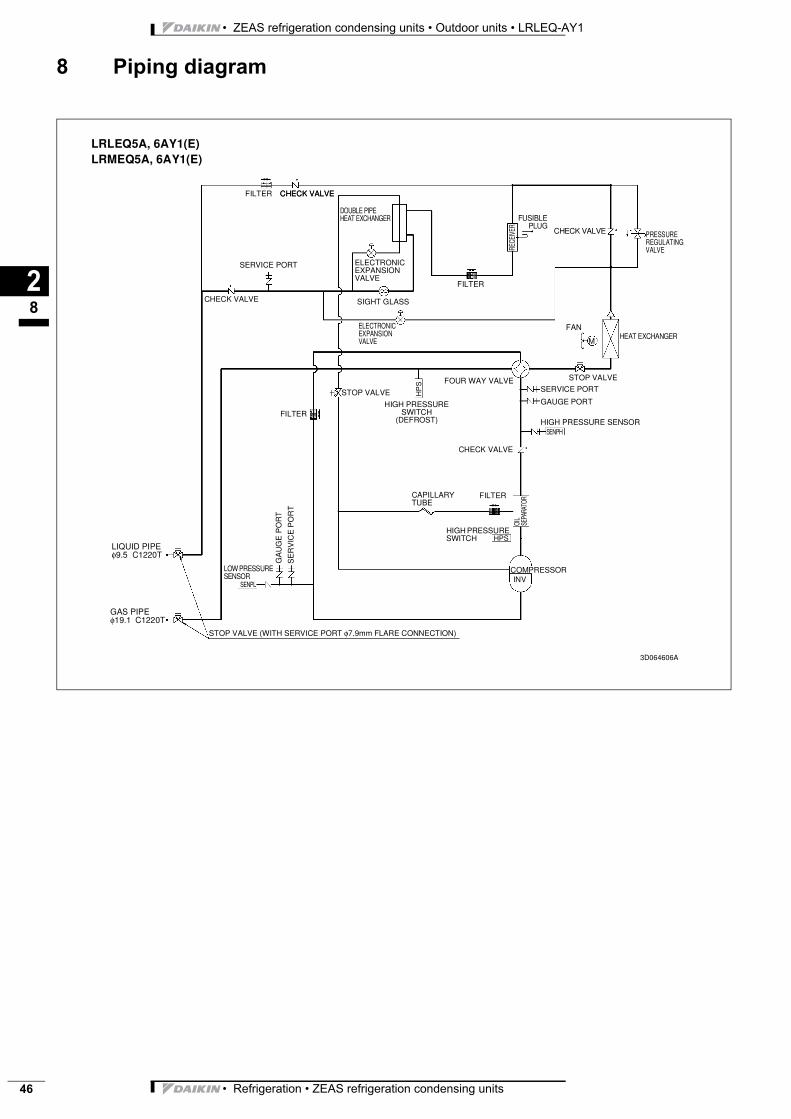
• ZEAS refrigeration condensing units • Outdoor units • LRLEQ-AY1
• Refrigeration • ZEAS refrigeration condensing units46
8 Piping diagram
28
LRLEQ5A, 6AY1(E)LRMEQ5A, 6AY1(E)
FILTER CHECK VALVE
DOUBLE PIPE HEAT EXCHANGER
SERVICE PORT
CHECK VALVE
ELECTRONIC EXPANSION VALVE
SIGHT GLASS
ELECTRONIC EXPANSION VALVE
FILTER
RECE
IVER
FUSIBLEPLUG
CHECK VALVE PRESSURE REGULATING VALVE
FAN
MHEAT EXCHANGER
FILTER
STOP VALVE
HIGH PRESSURE SWITCH
(DEFROST)
FOUR WAY VALVE STOP VALVE
SERVICE PORT
GAUGE PORT
HIGH PRESSURE SENSORSENPH
HP
S
CHECK VALVE
FILTERCAPILLARY TUBE
OIL
SEPA
RATO
RHIGH PRESSURE SWITCH HPS
COMPRESSORINV
LOW PRESSURE SENSOR
SENPL
GA
UG
E P
OR
T
SE
RV
ICE
PO
RT
LIQUID PIPE φ9.5 C1220T
GAS PIPE φ19.1 C1220T
STOP VALVE (WITH SERVICE PORT φ7.9mm FLARE CONNECTION)
3D064606A
CHECK VALVE
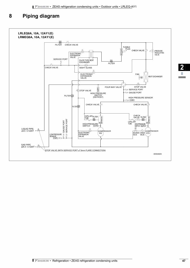
• Refrigeration • ZEAS refrigeration condensing units 47
• ZEAS refrigeration condensing units • Outdoor units • LRLEQ-AY1
8 Piping diagram
28
LRLEQ8A, 10A, 12AY1(E)LRMEQ8A, 10A, 12AY1(E)
FILTER CHECK VALVE
ELECTRONIC EXPANSION VALVE
SERVICE PORT
CHECK VALVE
PLATE TYPE HEAT EXCHANGER
SIGHT GLASS
ELECTRONIC EXPANSION VALVE
FILTER
RECE
IVER
FUSIBLEPLUG
CHECK VALVE PRESSURE REGULATING VALVE
FAN
M HEAT EXCHANGER
FILTER
STOP VALVEHIGH PRESSURE
SWITCH (DEFROST)
FOUR WAY VALVE STOP VALVESERVICE PORT
GAUGE PORT
HIGH PRESSURE SENSORS1NPH
S4P
H
CHECK VALVE
FILTERCAPILLARY TUBE
OIL
SEPA
RATO
R
HIGH PRESSURE SWITCH
COMPRESSORINV
LOW PRESSURE SENSOR
S1NPL
GA
UG
E P
OR
T
SE
RV
ICE
PO
RT
LIQUID PIPE φ9.5 C1220T
GAS PIPE φ25.4 C1220T
STOP VALVE (WITH SERVICE PORT φ7.9mm FLARE CONNECTION)
CHECK VALVEFILTER
S1PH
ELECTRONIC EXPANSION VALVE
OIL
SEPA
RATO
RFILTER
CAPILLARY TUBE HIGH PRESSURE
SWITCH S2PH
COMPRESSORSTD
CHECK VALVE
CHECK VALVE
SOLENOID VALVE
3D064605
SV
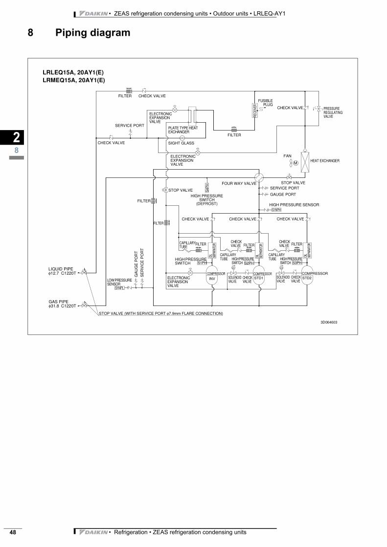
• ZEAS refrigeration condensing units • Outdoor units • LRLEQ-AY1
• Refrigeration • ZEAS refrigeration condensing units48
8 Piping diagram
28
LRLEQ15A, 20AY1(E)LRMEQ15A, 20AY1(E)
FILTER CHECK VALVE
ELECTRONIC EXPANSION VALVE
SERVICE PORT
CHECK VALVE
PLATE TYPE HEAT EXCHANGER
SIGHT GLASS
ELECTRONIC EXPANSION VALVE
FILTER
RECE
IVER
FUSIBLEPLUG
CHECK VALVE PRESSURE REGULATING VALVE
FAN
MHEAT EXCHANGER
FILTER
STOP VALVEHIGH PRESSURE
SWITCH (DEFROST)
FOUR WAY VALVE STOP VALVESERVICE PORT
GAUGE PORT
HIGH PRESSURE SENSORS1NPH
S4P
H
CHECK VALVE
FILTERCAPILLARY TUBE
OIL
SEPA
RATO
R
HIGH PRESSURE SWITCH
COMPRESSORINVLOW PRESSURE
SENSORS1NPL
GA
UG
E P
OR
T
SE
RV
ICE
PO
RT
LIQUID PIPE φ12.7 C1220T
GAS PIPE φ31.8 C1220T
STOP VALVE (WITH SERVICE PORT φ7.9mm FLARE CONNECTION)
CHECK VALVEFILTER
S1PH
ELECTRONIC EXPANSION VALVE
OIL
SEPA
RATO
R
CAPILLARY TUBE HIGH PRESSURE
SWITCH S3PH
COMPRESSORSTD2
CHECK VALVE
CHECK VALVE
SOLENOID VALVE
3D064603
CHECK VALVE
FILTER
OIL
SEPA
RATO
R
CAPILLARY TUBE HIGH PRESSURE
SWITCH S2PH
COMPRESSORSTD1
CHECK VALVE
CHECK VALVE
SOLENOID VALVE
FILTER
SV SV
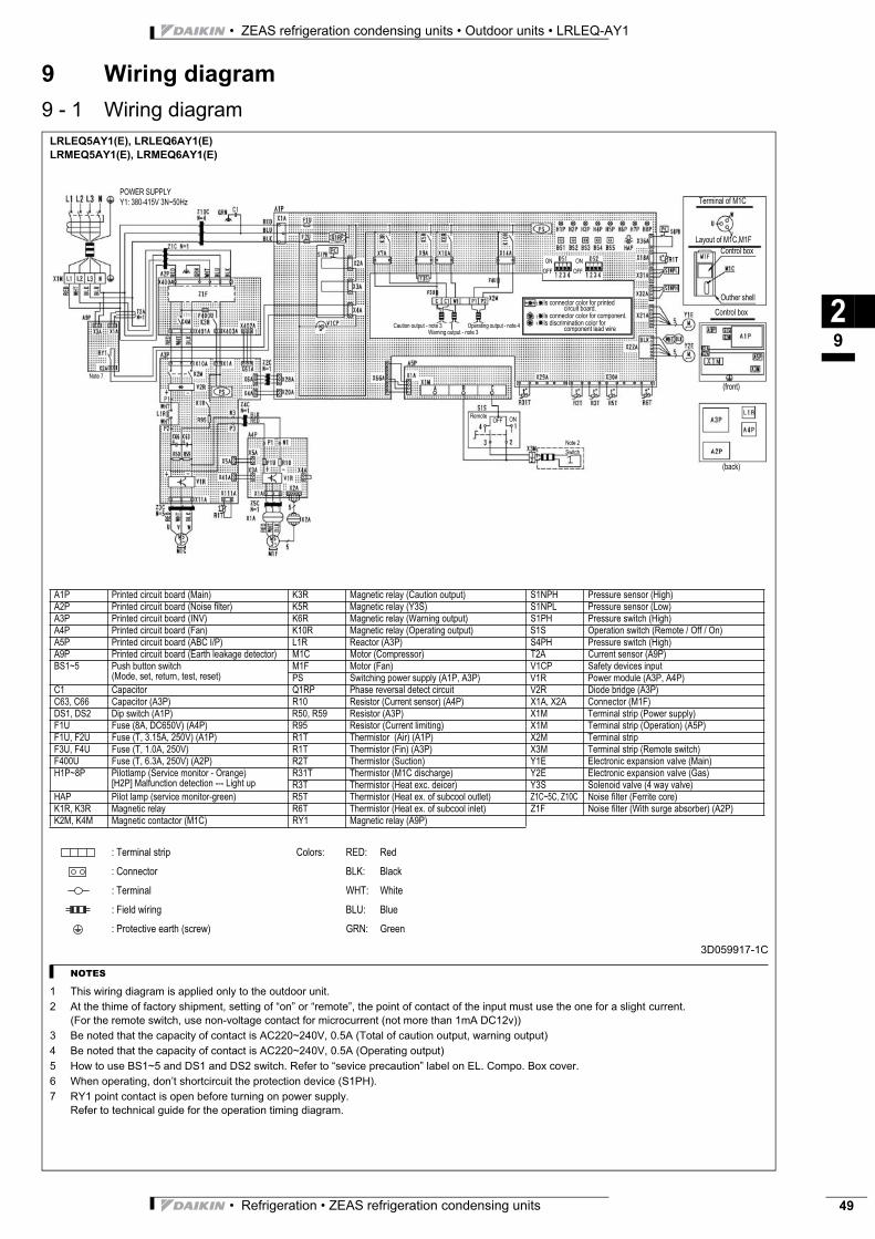
• Refrigeration • ZEAS refrigeration condensing units 49
• ZEAS refrigeration condensing units • Outdoor units • LRLEQ-AY1
9 Wiring diagram
9 - 1 Wiring diagram
29
LRLEQ5AY1(E), LRLEQ6AY1(E)
LRMEQ5AY1(E), LRMEQ6AY1(E)
3D059917-1C
NOTES
1 This wiring diagram is applied only to the outdoor unit.
2 At the thime of factory shipment, setting of “on” or “remote”, the point of contact of the input must use the one for a slight current.
(For the remote switch, use non-voltage contact for microcurrent (not more than 1mA DC12v))
3 Be noted that the capacity of contact is AC220~240V, 0.5A (Total of caution output, warning output)
4 Be noted that the capacity of contact is AC220~240V, 0.5A (Operating output)
5 How to use BS1~5 and DS1 and DS2 switch. Refer to “sevice precaution” label on EL. Compo. Box cover.
6 When operating, don’t shortcircuit the protection device (S1PH).
7 RY1 point contact is open before turning on power supply.
Refer to technical guide for the operation timing diagram.
A1P Printed circuit board (Main) K3R Magnetic relay (Caution output) S1NPH Pressure sensor (High)
A2P Printed circuit board (Noise filter) K5R Magnetic relay (Y3S) S1NPL Pressure sensor (Low)
A3P Printed circuit board (INV) K6R Magnetic relay (Warning output) S1PH Pressure switch (High)
A4P Printed circuit board (Fan) K10R Magnetic relay (Operating output) S1S Operation switch (Remote / Off / On)
A5P Printed circuit board (ABC I/P) L1R Reactor (A3P) S4PH Pressure switch (High)
A9P Printed circuit board (Earth leakage detector) M1C Motor (Compressor) T2A Current sensor (A9P)
BS1~5 Push button switch
(Mode, set, return, test, reset)
M1F Motor (Fan) V1CP Safety devices input
PS Switching power supply (A1P, A3P) V1R Power module (A3P, A4P)
C1 Capacitor Q1RP Phase reversal detect circuit V2R Diode bridge (A3P)
C63, C66 Capacitor (A3P) R10 Resistor (Current sensor) (A4P) X1A, X2A Connector (M1F)
DS1, DS2 Dip switch (A1P) R50, R59 Resistor (A3P) X1M Terminal strip (Power supply)
F1U Fuse (8A, DC650V) (A4P) R95 Resistor (Current limiting) X1M Terminal strip (Operation) (A5P)
F1U, F2U Fuse (T, 3.15A, 250V) (A1P) R1T Thermistor (Air) (A1P) X2M Terminal strip
F3U, F4U Fuse (T, 1.0A, 250V) R1T Thermistor (Fin) (A3P) X3M Terminal strip (Remote switch)
F400U Fuse (T, 6.3A, 250V) (A2P) R2T Thermistor (Suction) Y1E Electronic expansion valve (Main)
H1P~8P Pilotlamp (Service monitor - Orange)
[H2P] Malfunction detection --- Light up
R31T Thermistor (M1C discharge) Y2E Electronic expansion valve (Gas)
R3T Thermistor (Heat exc. deicer) Y3S Solenoid valve (4 way valve)
HAP Pilot lamp (service monitor-green) R5T Thermistor (Heat ex. of subcool outlet) Z1C~5C, Z10C Noise filter (Ferrite core)
K1R, K3R Magnetic relay R6T Thermistor (Heat ex. of subcool inlet) Z1F Noise filter (With surge absorber) (A2P)
K2M, K4M Magnetic contactor (M1C) RY1 Magnetic relay (A9P)
: Terminal strip Colors: RED: Red
: Connector BLK: Black
: Terminal WHT: White
: Field wiring BLU: Blue
: Protective earth (screw) GRN: Green
POWER SUPPLY
Y1: 380-415V 3N~50Hz Terminal of M1C
Layout of M1C,M1F
Control box
Outher shell
Control box
Is connector color for printed circuit board.
Is connector color for component.
Is discrimination color for component lead wire
(front)
(back)
ON
OFF
ON
OFF
ONOFFRemote
Note 2
Switch
Caution output - note 3
Warning output - note 3
Operating output - note 4
Note 7
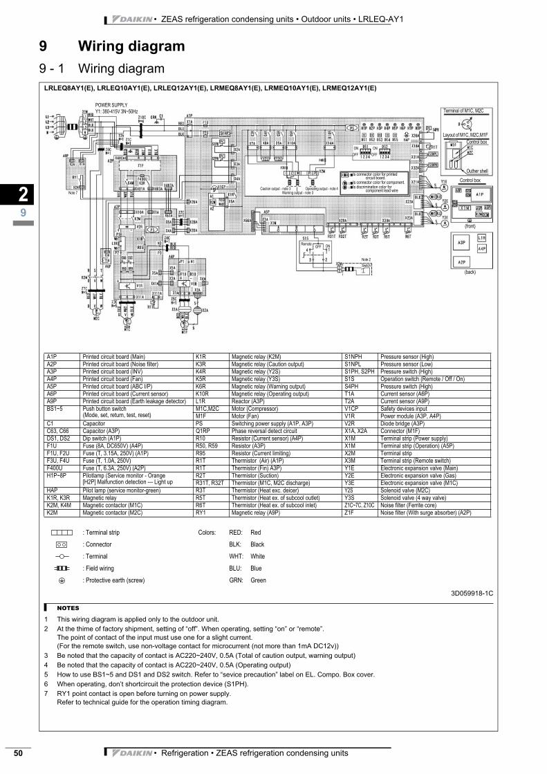
• ZEAS refrigeration condensing units • Outdoor units • LRLEQ-AY1
• Refrigeration • ZEAS refrigeration condensing units50
9 Wiring diagram
9 - 1 Wiring diagram
29
LRLEQ8AY1(E), LRLEQ10AY1(E), LRLEQ12AY1(E), LRMEQ8AY1(E), LRMEQ10AY1(E), LRMEQ12AY1(E)
3D059918-1C
NOTES
1 This wiring diagram is applied only to the outdoor unit.
2 At the thime of factory shipment, setting of “off”. When operating, setting “on” or “remote”.
The point of contact of the input must use one for a slight current.
(For the remote switch, use non-voltage contact for microcurrent (not more than 1mA DC12v))
3 Be noted that the capacity of contact is AC220~240V, 0.5A (Total of caution output, warning output)
4 Be noted that the capacity of contact is AC220~240V, 0.5A (Operating output)
5 How to use BS1~5 and DS1 and DS2 switch. Refer to “sevice precaution” label on EL. Compo. Box cover.
6 When operating, don’t shortcircuit the protection device (S1PH).
7 RY1 point contact is open before turning on power supply.
Refer to technical guide for the operation timing diagram.
A1P Printed circuit board (Main) K1R Magnetic relay (K2M) S1NPH Pressure sensor (High)
A2P Printed circuit board (Noise filter) K3R Magnetic relay (Caution output) S1NPL Pressure sensor (Low)
A3P Printed circuit board (INV) K4R Magnetic relay (Y2S) S1PH, S2PH Pressure switch (High)
A4P Printed circuit board (Fan) K5R Magnetic relay (Y3S) S1S Operation switch (Remote / Off / On)
A5P Printed circuit board (ABC I/P) K6R Magnetic relay (Warning output) S4PH Pressure switch (High)
A6P Printed circuit board (Current sensor) K10R Magnetic relay (Operating output) T1A Current sensor (A6P)
A9P Printed circuit board (Earth leakage detector) L1R Reactor (A3P) T2A Current sensor (A9P)
BS1~5 Push button switch
(Mode, set, return, test, reset)
M1C,M2C Motor (Compressor) V1CP Safety devices input
M1F Motor (Fan) V1R Power module (A3P, A4P)
C1 Capacitor PS Switching power supply (A1P, A3P) V2R Diode bridge (A3P)
C63, C66 Capacitor (A3P) Q1RP Phase reversal detect circuit X1A, X2A Connector (M1F)
DS1, DS2 Dip switch (A1P) R10 Resistor (Current sensor) (A4P) X1M Terminal strip (Power supply)
F1U Fuse (8A, DC650V) (A4P) R50, R59 Resistor (A3P) X1M Terminal strip (Operation) (A5P)
F1U, F2U Fuse (T, 3.15A, 250V) (A1P) R95 Resistor (Current limiting) X2M Terminal strip
F3U, F4U Fuse (T, 1.0A, 250V) R1T Thermistor (Air) (A1P) X3M Terminal strip (Remote switch)
F400U Fuse (T, 6.3A, 250V) (A2P) R1T Thermistor (Fin) A3P) Y1E Electronic expansion valve (Main)
H1P~8P Pilotlamp (Service monitor - Orange
[H2P] Malfunction detection --- Light up
R2T Thermistor (Suction) Y2E Electronic expansion valve (Gas)
R31T, R32T Thermistor (M1C, M2C discharge) Y3E Electronic expansion valve (M1C)
HAP Pilot lamp (service monitor-green) R3T Thermistor (Heat exc. deicer) Y2S Solenoid valve (M2C)
K1R, K3R Magnetic relay R5T Thermistor (Heat ex. of subcool outlet) Y3S Solenoid valve (4 way valve)
K2M, K4M Magnetic contactor (M1C) R6T Thermistor (Heat ex. of subcool inlet) Z1C~7C, Z10C Noise filter (Ferrite core)
K2M Magnetic contactor (M2C) RY1 Magnetic relay (A9P) Z1F Noise filter (With surge absorber) (A2P)
: Terminal strip Colors: RED: Red
: Connector BLK: Black
: Terminal WHT: White
: Field wiring BLU: Blue
: Protective earth (screw) GRN: Green
POWER SUPPLY
Y1: 380-415V 3N~50Hz Terminal of M1C, M2C
Layout of M1C, M2C,M1F
Control box
Outher shell
Control box
Is connector color for printed circuit board.
Is connector color for component.
Is discrimination color for component lead wire
(front)
(back)
ON
OFF
ON
OFF
ONOFFRemote
Note 2
Switch
Caution output - note 3
Warning output - note 3
Operating output - note 4
Note 7
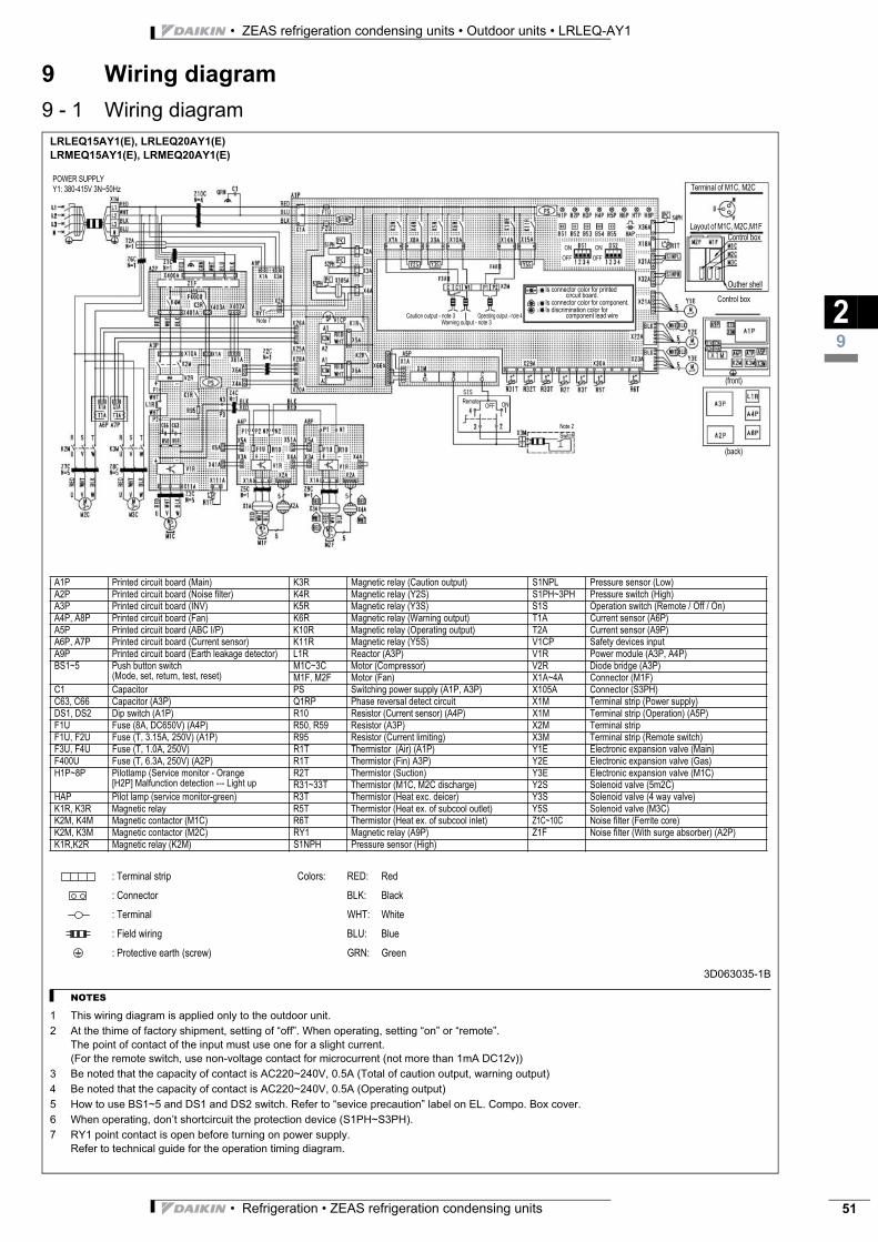
• Refrigeration • ZEAS refrigeration condensing units 51
• ZEAS refrigeration condensing units • Outdoor units • LRLEQ-AY1
9 Wiring diagram
9 - 1 Wiring diagram
29
LRLEQ15AY1(E), LRLEQ20AY1(E)
LRMEQ15AY1(E), LRMEQ20AY1(E)
3D063035-1B
NOTES
1 This wiring diagram is applied only to the outdoor unit.
2 At the thime of factory shipment, setting of “off”. When operating, setting “on” or “remote”.
The point of contact of the input must use one for a slight current.
(For the remote switch, use non-voltage contact for microcurrent (not more than 1mA DC12v))
3 Be noted that the capacity of contact is AC220~240V, 0.5A (Total of caution output, warning output)
4 Be noted that the capacity of contact is AC220~240V, 0.5A (Operating output)
5 How to use BS1~5 and DS1 and DS2 switch. Refer to “sevice precaution” label on EL. Compo. Box cover.
6 When operating, don’t shortcircuit the protection device (S1PH~S3PH).
7 RY1 point contact is open before turning on power supply.
Refer to technical guide for the operation timing diagram.
A1P Printed circuit board (Main) K3R Magnetic relay (Caution output) S1NPL Pressure sensor (Low)
A2P Printed circuit board (Noise filter) K4R Magnetic relay (Y2S) S1PH~3PH Pressure switch (High)
A3P Printed circuit board (INV) K5R Magnetic relay (Y3S) S1S Operation switch (Remote / Off / On)
A4P, A8P Printed circuit board (Fan) K6R Magnetic relay (Warning output) T1A Current sensor (A6P)
A5P Printed circuit board (ABC I/P) K10R Magnetic relay (Operating output) T2A Current sensor (A9P)
A6P, A7P Printed circuit board (Current sensor) K11R Magnetic relay (Y5S) V1CP Safety devices input
A9P Printed circuit board (Earth leakage detector) L1R Reactor (A3P) V1R Power module (A3P, A4P)
BS1~5 Push button switch
(Mode, set, return, test, reset)
M1C~3C Motor (Compressor) V2R Diode bridge (A3P)
M1F, M2F Motor (Fan) X1A~4A Connector (M1F)
C1 Capacitor PS Switching power supply (A1P, A3P) X105A Connector (S3PH)
C63, C66 Capacitor (A3P) Q1RP Phase reversal detect circuit X1M Terminal strip (Power supply)
DS1, DS2 Dip switch (A1P) R10 Resistor (Current sensor) (A4P) X1M Terminal strip (Operation) (A5P)
F1U Fuse (8A, DC650V) (A4P) R50, R59 Resistor (A3P) X2M Terminal strip
F1U, F2U Fuse (T, 3.15A, 250V) (A1P) R95 Resistor (Current limiting) X3M Terminal strip (Remote switch)
F3U, F4U Fuse (T, 1.0A, 250V) R1T Thermistor (Air) (A1P) Y1E Electronic expansion valve (Main)
F400U Fuse (T, 6.3A, 250V) (A2P) R1T Thermistor (Fin) A3P) Y2E Electronic expansion valve (Gas)
H1P~8P Pilotlamp (Service monitor - Orange
[H2P] Malfunction detection --- Light up
R2T Thermistor (Suction) Y3E Electronic expansion valve (M1C)
R31~33T Thermistor (M1C, M2C discharge) Y2S Solenoid valve (5m2C)
HAP Pilot lamp (service monitor-green) R3T Thermistor (Heat exc. deicer) Y3S Solenoid valve (4 way valve)
K1R, K3R Magnetic relay R5T Thermistor (Heat ex. of subcool outlet) Y5S Solenoid valve (M3C)
K2M, K4M Magnetic contactor (M1C) R6T Thermistor (Heat ex. of subcool inlet) Z1C~10C Noise filter (Ferrite core)
K2M, K3M Magnetic contactor (M2C) RY1 Magnetic relay (A9P) Z1F Noise filter (With surge absorber) (A2P)
K1R,K2R Magnetic relay (K2M) S1NPH Pressure sensor (High)
: Terminal strip Colors: RED: Red
: Connector BLK: Black
: Terminal WHT: White
: Field wiring BLU: Blue
: Protective earth (screw) GRN: Green
POWER SUPPLY
Y1: 380-415V 3N~50Hz Terminal of M1C, M2C
Layout of M1C, M2C,M1F
Control box
Outher shell
Control box
Is connector color for printed circuit board.
Is connector color for component.
Is discrimination color for component lead wire
(front)
(back)
ON
OFF
ON
OFF
ONOFFRemote
Note 2
Switch
Caution output - note 3
Warning output - note 3
Operating output - note 4Note 7
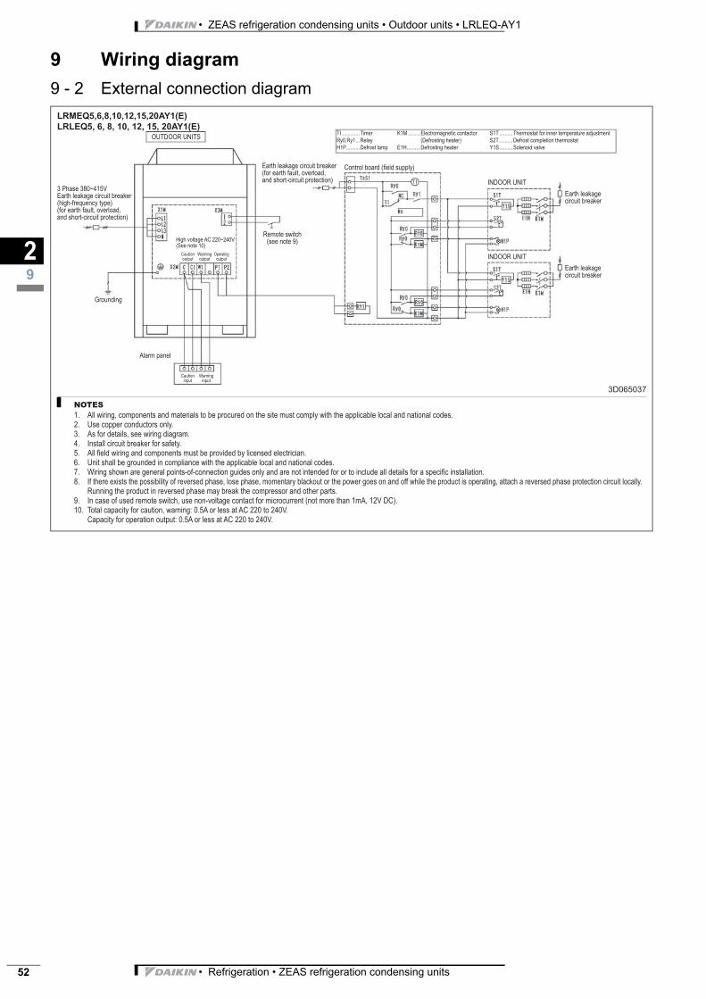
• ZEAS refrigeration condensing units • Outdoor units • LRLEQ-AY1
• Refrigeration • ZEAS refrigeration condensing units52
9 Wiring diagram
9 - 2 External connection diagram
29
LRMEQ5,6,8,10,12,15,20AY1(E)
LRLEQ5, 6, 8, 10, 12, 15, 20AY1(E)
3D065037
NOTES
All wiring, components and materials to be procured on the site must comply with the applicable local and national codes.
Use copper conductors only.
As for details, see wiring diagram.
Install circuit breaker for safety.
All fi eld wiring and components must be provided by licensed electrician.
Unit shall be grounded in compliance with the applicable local and national codes.
Wiring shown are general points-of-connection guides only and are not intended for or to include all details for a specifi c installation.
If there exists the possibility of reversed phase, lose phase, momentary blackout or the power goes on and off while the product is operating, attach a reversed phase protection circuit locally.
Running the product in reversed phase may break the compressor and other parts.
In case of used remote switch, use non-voltage contact for microcurrent (not more than 1mA, 12V DC).
Total capacity for caution, warning: 0.5A or less at AC 220 to 240V.
Capacity for operation output: 0.5A or less at AC 220 to 240V.
1.
2.
3.
4.
5.
6.
7.
8.
9.
10.
OUTDOOR UNITS
3 Phase 380~415V
Earth leakage circuit breaker
(high-frequency type)
(for earth fault, overload,
and short-circuit protection)
Grounding
Alarm panel
Caution
input
Warning
input
High voltage AC 220~240V
(See note 10)
Caution
output
Warning
output
Operating
output
Remote switch
(see note 9)
Earth leakage circuit breaker
(for earth fault, overload,
and short-circuit protection)
Control board (fi eld supply)
INDOOR UNIT
INDOOR UNIT
TI .............Timer
Ry0,Ry1 ...Relay
H1P ..........Defrost lamp
K1M .........Electromagnetic contactor
(Defrosting heater)
E1H ..........Defrosting heater
S1T ..........Thermostat for inner temperature adjustment
S2T ..........Defrost completion thermostat
Y1S ..........Solenoid valve
Earth leakage
circuit breaker
Earth leakage
circuit breaker
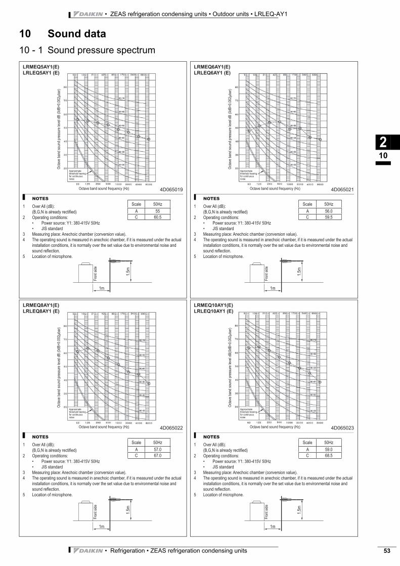
• Refrigeration • ZEAS refrigeration condensing units 53
• ZEAS refrigeration condensing units • Outdoor units • LRLEQ-AY1
10 Sound data
10 - 1 Sound pressure spectrum
210
LRMEQ5AY1(E)
LRLEQ5AY1 (E)
4D065019
NOTES
1 Over All (dB):
(B,G,N is already rectifi ed)
2 Operating conditions:
Power source: Y1: 380-415V 50Hz
JIS standard
3 Measuring place: Anechoic chamber (conversion value).
4 The operating sound is measured in anechoic chamber, if it is measured under the actual
installation conditions, it is normally over the set value due to environmental noise and
sound refl ection.
5 Location of microphone.
•
•
Octa
ve
ba
nd
so
un
d p
ressu
re le
ve
l d
B (
0d
B=
0.0
02
ba
r)
Octave band sound frequency (Hz)
Approximate
threshold hearing
for continuous
noise
Fro
nt
sid
e
1m
1.5
m
Scale 50Hz
A 55
C 60.5
LRMEQ6AY1(E)
LRLEQ6AY1 (E)
4D065021
NOTES
1 Over All (dB):
(B,G,N is already rectifi ed)
2 Operating conditions:
Power source: Y1: 380-415V 50Hz
JIS standard
3 Measuring place: Anechoic chamber (conversion value).
4 The operating sound is measured in anechoic chamber, if it is measured under the actual
installation conditions, it is normally over the set value due to environmental noise and
sound refl ection.
5 Location of microphone.
•
•O
cta
ve
ba
nd
so
un
d p
ressu
re le
ve
l d
B (
0d
B=
0.0
02
ba
r)
Octave band sound frequency (Hz)
Approximate
threshold hearing
for continuous
noise
Fro
nt
sid
e
1m
1.5
m
Scale 50Hz
A 56.0
C 59.5
LRMEQ8AY1(E)
LRLEQ8AY1 (E)
4D065022
NOTES
1 Over All (dB):
(B,G,N is already rectifi ed)
2 Operating conditions:
Power source: Y1: 380-415V 50Hz
JIS standard
3 Measuring place: Anechoic chamber (conversion value).
4 The operating sound is measured in anechoic chamber, if it is measured under the actual
installation conditions, it is normally over the set value due to environmental noise and
sound refl ection.
5 Location of microphone.
•
•
Octa
ve
ba
nd
so
un
d p
ressu
re le
ve
l d
B (
0d
B=
0.0
02
ba
r)
Octave band sound frequency (Hz)
Approximate
threshold hearing
for continuous
noise
Fro
nt
sid
e
1m
1.5
m
Scale 50Hz
A 57.0
C 67.0
LRMEQ10AY1(E)
LRLEQ10AY1 (E)
4D065023
NOTES
1 Over All (dB):
(B,G,N is already rectifi ed)
2 Operating conditions:
Power source: Y1: 380-415V 50Hz
JIS standard
3 Measuring place: Anechoic chamber (conversion value).
4 The operating sound is measured in anechoic chamber, if it is measured under the actual
installation conditions, it is normally over the set value due to environmental noise and
sound refl ection.
5 Location of microphone.
•
•
Octa
ve
ba
nd
so
un
d p
ressu
re le
ve
l d
B(0
dB
=0
.00
2b
ar)
Octave band sound frequency (Hz)
Approximate
threshold hearing
for continuous
noise
Fro
nt
sid
e
1m
1.5
m
Scale 50Hz
A 59.0
C 68.5
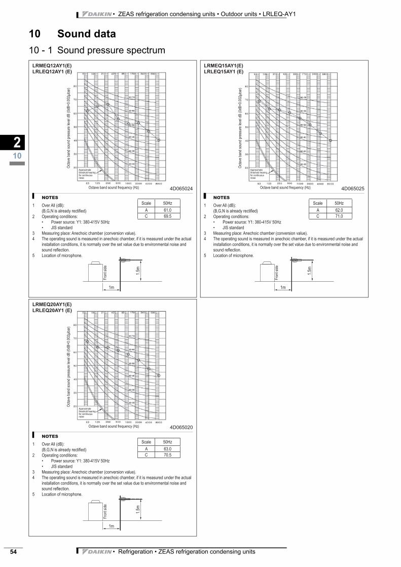
• ZEAS refrigeration condensing units • Outdoor units • LRLEQ-AY1
• Refrigeration • ZEAS refrigeration condensing units54
10 Sound data
10 - 1 Sound pressure spectrum
210
LRMEQ12AY1(E)
LRLEQ12AY1 (E)
4D065024
NOTES
1 Over All (dB):
(B,G,N is already rectifi ed)
2 Operating conditions:
Power source: Y1: 380-415V 50Hz
JIS standard
3 Measuring place: Anechoic chamber (conversion value).
4 The operating sound is measured in anechoic chamber, if it is measured under the actual
installation conditions, it is normally over the set value due to environmental noise and
sound refl ection.
5 Location of microphone.
•
•
Octa
ve
ba
nd
so
un
d p
ressu
re le
ve
l d
B (
0d
B=
0.0
02
ba
r)
Octave band sound frequency (Hz)
Approximate
threshold hearing
for continuous
noise
Fro
nt
sid
e
1m
1.5
m
Scale 50Hz
A 61.0
C 69.5
LRMEQ15AY1(E)
LRLEQ15AY1 (E)
4D065025
NOTES
1 Over All (dB):
(B,G,N is already rectifi ed)
2 Operating conditions:
Power source: Y1: 380-415V 50Hz
JIS standard
3 Measuring place: Anechoic chamber (conversion value).
4 The operating sound is measured in anechoic chamber, if it is measured under the actual
installation conditions, it is normally over the set value due to environmental noise and
sound refl ection.
5 Location of microphone.
•
•
Octa
ve
ba
nd
so
un
d p
ressu
re le
ve
l d
B (
0d
B=
0.0
02
ba
r)
Octave band sound frequency (Hz)
Approximate
threshold hearing
for continuous
noise
Fro
nt
sid
e
1m
1.5
m
Scale 50Hz
A 62.0
C 71.0
LRMEQ20AY1(E)
LRLEQ20AY1 (E)
4D065020
NOTES
1 Over All (dB):
(B,G,N is already rectifi ed)
2 Operating conditions:
Power source: Y1: 380-415V 50Hz
JIS standard
3 Measuring place: Anechoic chamber (conversion value).
4 The operating sound is measured in anechoic chamber, if it is measured under the actual
installation conditions, it is normally over the set value due to environmental noise and
sound refl ection.
5 Location of microphone.
•
•
Octa
ve
ba
nd
so
un
d p
ressu
re le
ve
l d
B (
0d
B=
0.0
02
ba
r)
Octave band sound frequency (Hz)
Approximate
threshold hearing
for continuous
noise
Fro
nt
sid
e
1m
1.5
m
Scale 50Hz
A 63.0
C 70.5
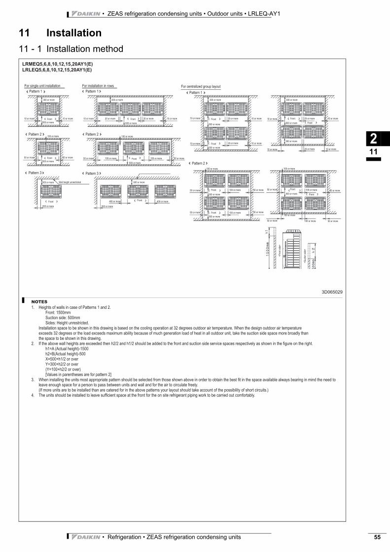
• Refrigeration • ZEAS refrigeration condensing units 55
• ZEAS refrigeration condensing units • Outdoor units • LRLEQ-AY1
11 Installation
11 - 1 Installation method
211
LRMEQ5,6,8,10,12,15,20AY1(E)
LRLEQ5,6,8,10,12,15,20AY1(E)
3D065029
NOTES
Heights of walls in case of Patterns 1 and 2.
Front: 1500mm
Suction side: 500mm
Sides: Height unrestricted.
Installation space to be shown in this drawing is based on the cooling operation at 32 degrees outdoor air temperature. When the design outdoor air temperature
exceeds 32 degrees or the load exceeds maximum ability because of much generation load of heat in all outdoor unit, take the suction side space more broadly than
the space to be shown in this drawing.
If the above wall heights are exceeded then h2/2 and h1/2 should be added to the front and suction side service spaces respectively as shown in the fi gure on the right.
h1=A (Actual height)-1500
h2=B(Actual height)-500
X=500+h1/2 or over
Y=300+h2/2 or over
(Y=100+h2/2 or over)
[Values in parentheses are for pattern 2]
When installing the units most appropriate pattern should be selected from those shown above in order to obtain the best fi t in the space available always bearing in mind the need to
leave enough space for a person to pass between units and wall and for the air to circulate freely.
(If more units are to be installed than are catered for in the above patterns your layout should take account of the possibility of short circuits.)
The units should be installed to leave suffi cient space at the front for the on site refrigerant piping work to be carried out comfortably.
1.
2.
3.
4.
For single unit installation For installation in rows For centralized group layout
Pattern 1 Pattern 1 Pattern 1
Pattern 2 Pattern 2
Pattern 2
Pattern 3 Pattern 3
300 or more
10 or more 10 or moreFront
500 or more
100 or more
50 or more 50 or moreFront
500 or more
Front
200 or more
300 or more Wall height unrestricted
300 or more
10 or more 20 or more
500 or more
20 or more 10 or moreFront
100 or more
50 or more 100 or more
500 or more
100 or more 50 or moreFront
200 or more
Front400 or more 400 or more
300 or more
300 or more
10 or more 20 or moreFront 10 or more
600 or more
10 or more 10 or more20 or moreFront
500 or more
100 or more
50 or more 100 or moreFront 50 or more
500 or more
50 or more 50 or more100 or moreFront
500 or more
300 or more
10 or more 20 or moreFront 10 or more
500 or more
10 or more 10 or more20 or more
300 or more
100 or more
50 or more 100 or moreFront50 or more
500 or more
50 or more 50 or more100 or more
100 or more
Front
Front
<F
ront sid
e>
<S
uction s
ide>
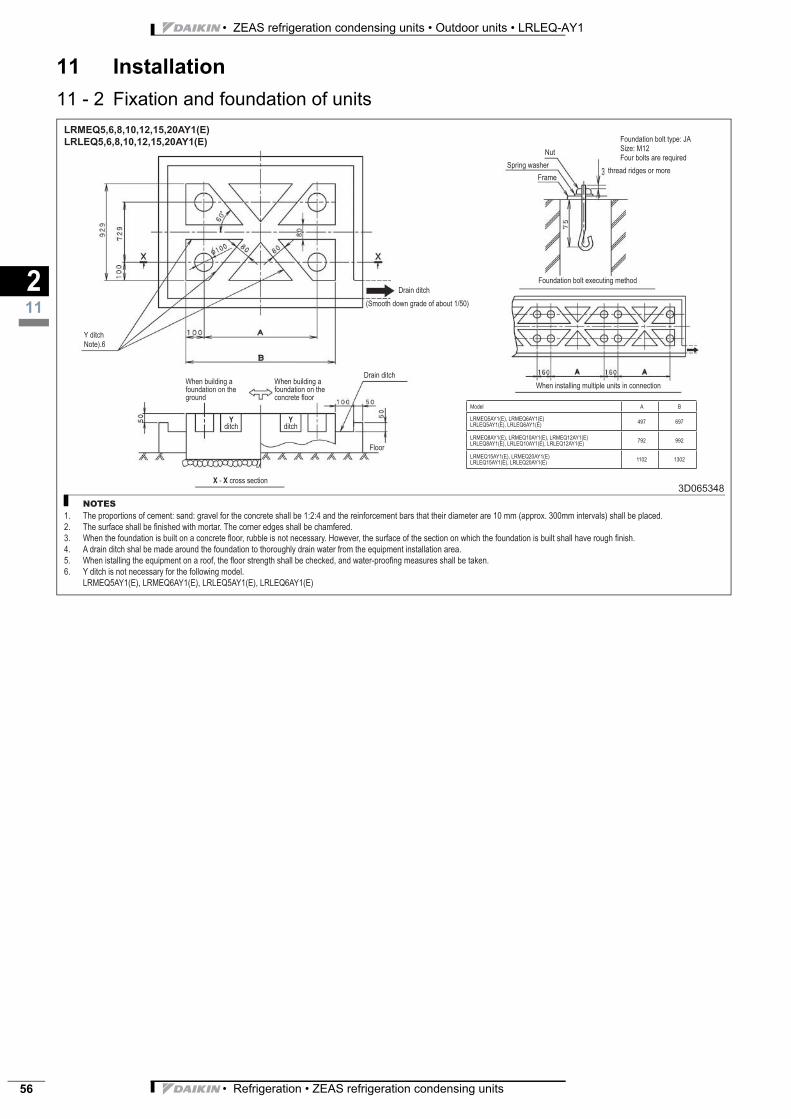
• ZEAS refrigeration condensing units • Outdoor units • LRLEQ-AY1
• Refrigeration • ZEAS refrigeration condensing units56
11 Installation
11 - 2 Fixation and foundation of units
211
LRMEQ5,6,8,10,12,15,20AY1(E)
LRLEQ5,6,8,10,12,15,20AY1(E)
3D065348
NOTES
The proportions of cement: sand: gravel for the concrete shall be 1:2:4 and the reinforcement bars that their diameter are 10 mm (approx. 300mm intervals) shall be placed.
The surface shall be fi nished with mortar. The corner edges shall be chamfered.
When the foundation is built on a concrete fl oor, rubble is not necessary. However, the surface of the section on which the foundation is built shall have rough fi nish.
A drain ditch shal be made around the foundation to thoroughly drain water from the equipment installation area.
When istalling the equipment on a roof, the fl oor strength shall be checked, and water-proofi ng measures shall be taken.
Y ditch is not necessary for the following model.
LRMEQ5AY1(E), LRMEQ6AY1(E), LRLEQ5AY1(E), LRLEQ6AY1(E)
1.
2.
3.
4.
5.
6.
Y ditch
Note).6
Drain ditch
(Smooth down grade of about 1/50)
When building a
foundation on the
ground
When building a
foundation on the
concrete fl oor
Drain ditch
Floor
X - X cross section
Yditch
Yditch
Nut
Spring washer
Frame
Foundation bolt executing method
When installing multiple units in connection
Foundation bolt type: JA
Size: M12
Four bolts are required
thread ridges or more
Model A B
LRMEQ5AY1(E), LRMEQ6AY1(E)
LRLEQ5AY1(E), LRLEQ6AY1(E)497 697
LRMEQ8AY1(E), LRMEQ10AY1(E), LRMEQ12AY1(E)
LRLEQ8AY1(E), LRLEQ10AY1(E), LRLEQ12AY1(E)792 992
LRMEQ15AY1(E), LRMEQ20AY1(E)
LRLEQ15AY1(E), LRLEQ20AY1(E)1102 1302
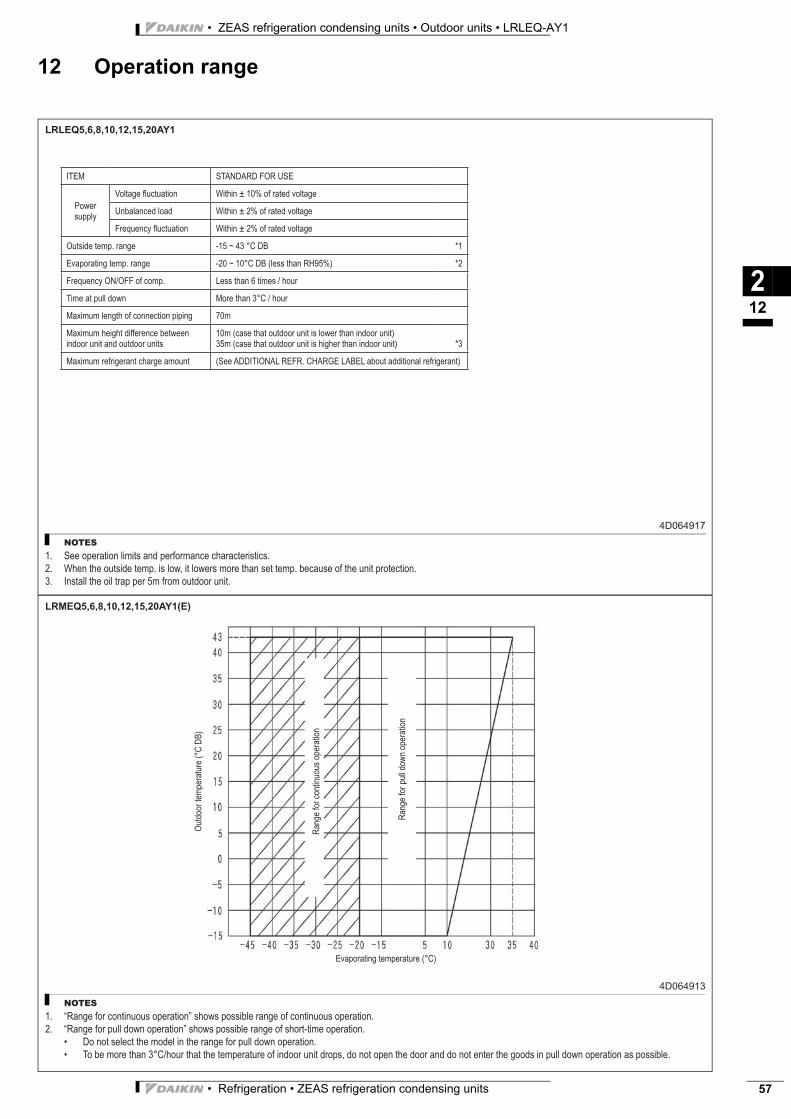
• Refrigeration • ZEAS refrigeration condensing units 57
• ZEAS refrigeration condensing units • Outdoor units • LRLEQ-AY1
12 Operation range
212
LRLEQ5,6,8,10,12,15,20AY1
4D064917
NOTES
See operation limits and performance characteristics.
When the outside temp. is low, it lowers more than set temp. because of the unit protection.
Install the oil trap per 5m from outdoor unit.
1.
2.
3.
ITEM STANDARD FOR USE
Power
supply
Voltage fl uctuation Within ± 10% of rated voltage
Unbalanced load Within ± 2% of rated voltage
Frequency fl uctuation Within ± 2% of rated voltage
Outside temp. range -15 ~ 43 °C DB *1
Evaporating temp. range -20 ~ 10°C DB (less than RH95%) *2
Frequency ON/OFF of comp. Less than 6 times / hour
Time at pull down More than 3°C / hour
Maximum length of connection piping 70m
Maximum height difference between
indoor unit and outdoor units
10m (case that outdoor unit is lower than indoor unit)
35m (case that outdoor unit is higher than indoor unit) *3
Maximum refrigerant charge amount (See ADDITIONAL REFR. CHARGE LABEL about additional refrigerant)
LRMEQ5,6,8,10,12,15,20AY1(E)
4D064913
NOTES
“Range for continuous operation” shows possible range of continuous operation.
“Range for pull down operation” shows possible range of short-time operation.
Do not select the model in the range for pull down operation.
To be more than 3°C/hour that the temperature of indoor unit drops, do not open the door and do not enter the goods in pull down operation as possible.
1.
2.
•
•
Outd
oor
tem
pera
ture
(°C
DB
)
Range for
continuous o
pera
tion
Range for
pull d
ow
n o
pera
tion
Evaporating temperature (°C)

• ZEAS refrigeration condensing units • Outdoor units • LRLEQ-AY1
• Refrigeration • ZEAS refrigeration condensing units58
12 Operation range
212
LRMEQ
-AY1 / LRLEQ-AY1
ÈEEDEN09-7415ËÍ
Daikin Europe N.V. is approved by LRQA for its QualityManagement System in accordance with the ISO9001standard. ISO9001 pertains to quality assurance regardingdesign, development, manufacturing as well as to servicesrelated to the product.
Daikin units comply with the European regulations thatguarantee the safety of the product.
EED
EN09
-741
• C
D •
09/2
009
• Cop
yrig
ht D
aiki
nTh
e pr
esen
t pub
licat
ion
supe
rsed
es E
EDEN
08-2
04Pr
epar
ed in
Bel
gium
by
Lann
oo (
ww
w.la
nnoo
prin
t.be)
, a c
ompa
ny w
hose
con
cern
for
the
envi
ronm
ont i
s se
t in
the
EMAS
and
ISO
140
01 s
yste
ms.
Res
pons
ible
Edi
tor:
Dai
kin
Euro
pe N
.V.,
Zand
voor
dest
raat
300
, B- 8
400
Oos
tend
e
The present publication is drawn up by way of information only and does notconstitute an offer binding upon Daikin Europe N.V.. Daikin Europe N.V. hascompiled the content of this publication to the best of its knowledge. Noexpress or implied warranty is given for the completeness, accuracy,reliability or fitness for particular purpose of its content and the products andservices presented therein. Specifications are subject to change withoutprior notice. Daikin Europe N.V. explicitly rejects any liability for any direct orindirect damage, in the broadest sense, arising from or related to the useand/or interpretation of this publication. All content is copyrighted by DaikinEurope N.V..
Naamloze VennootschapZandvoordestraat 300B-8400 Oostende, Belgiumwww.daikin.euBE 0412 120 336RPR Oostende
Daikin’s unique position as a manufacturer of airconditioning equipment, compressors andrefrigerants has led to its close involvement inenvironmental issues. For several years Daikin hashad the intension to become a leader in the provisionof products that have limited impact on theenvironment. This challenge demands the eco designand development of a wide range of products and anenergy management system, resulting in energyconservation and a reduction of waste.
ISO14001 assures an effective environmentalmanagement system in order to help protect human healthand the environment from the potential impact of ouractivities, products and services and to assist inmaintaining and improving the quality of the environment.
LRMEQ-AY1LRLEQ-AY1
refrige
ration
EEDEN09-741
LRMEQ-AY1LRLEQ-AY1
technical data
EED09-741.fm Page 1 Tuesday, September 15, 2009 2:57 PM