EE101: Resonance in RLC circuitssequel/ee101/ee101_resonance.pdf · 2015-06-30 · Resonance in...
44
EE101: Resonance in RLC circuits M. B. Patil [email protected] www.ee.iitb.ac.in/~sequel Department of Electrical Engineering Indian Institute of Technology Bombay M. B. Patil, IIT Bombay
Transcript of EE101: Resonance in RLC circuitssequel/ee101/ee101_resonance.pdf · 2015-06-30 · Resonance in...
EE101: Resonance in RLC circuits
M. B. [email protected]
www.ee.iitb.ac.in/~sequel
Department of Electrical EngineeringIndian Institute of Technology Bombay
M. B. Patil, IIT Bombay
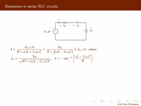
Resonance in series RLC circuits
I
VC
VLVR
Vm 6 0
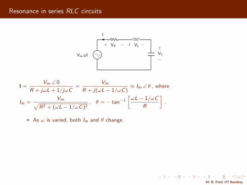
I =Vm ∠ 0
R + jωL + 1/jωC=
Vm
R + j(ωL− 1/ωC)≡ Im ∠ θ , where
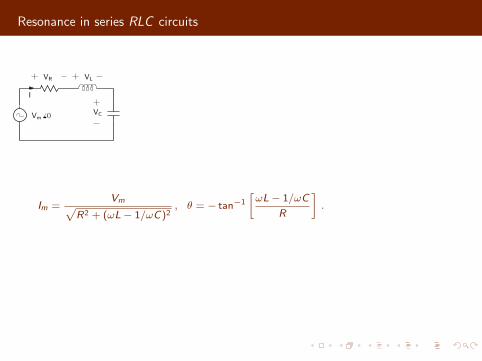
Im =Vmp
R2 + (ωL− 1/ωC)2, θ = − tan−1
»ωL− 1/ωC
R
–.
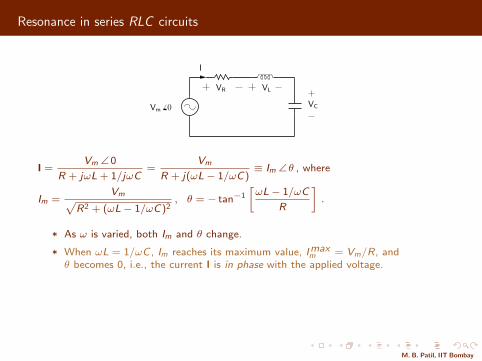
* As ω is varied, both Im and θ change.
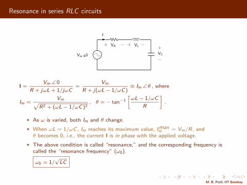
* When ωL = 1/ωC , Im reaches its maximum value, Imaxm = Vm/R, and
θ becomes 0, i.e., the current I is in phase with the applied voltage.
* The above condition is called “resonance,” and the corresponding frequency iscalled the “resonance frequency” (ω0).
ω0 = 1/√
LC
M. B. Patil, IIT Bombay
Resonance in series RLC circuits
I
VC
VLVR
Vm 6 0
I =Vm ∠ 0
R + jωL + 1/jωC=
Vm
R + j(ωL− 1/ωC)≡ Im ∠ θ , where
Im =Vmp
R2 + (ωL− 1/ωC)2, θ = − tan−1
»ωL− 1/ωC
R
–.
* As ω is varied, both Im and θ change.
* When ωL = 1/ωC , Im reaches its maximum value, Imaxm = Vm/R, and
θ becomes 0, i.e., the current I is in phase with the applied voltage.
* The above condition is called “resonance,” and the corresponding frequency iscalled the “resonance frequency” (ω0).
ω0 = 1/√
LC
M. B. Patil, IIT Bombay
Resonance in series RLC circuits
I
VC
VLVR
Vm 6 0
Frequency (Hz)
0.1
0
I m(A
)
f0
105104103102
L = 1mHC = 1µF
R = 10Ω
Frequency (Hz)
f0
0
−90
90
θ(d
egre
es)
105104103102
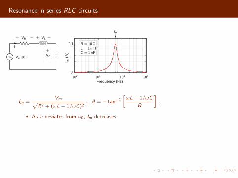
Im =Vmp
R2 + (ωL− 1/ωC)2, θ = − tan−1
»ωL− 1/ωC
R
–.
* As ω deviates from ω0, Im decreases.
* As ω → 0, the term 1/ωC dominates, and θ → π/2.
* As ω →∞, the term ωL dominates, and θ → −π/2.
(SEQUEL file: ee101 reso rlc 1.sqproj)
M. B. Patil, IIT Bombay
Resonance in series RLC circuits
I
VC
VLVR
Vm 6 0
Frequency (Hz)
0.1
0
I m(A
)
f0
105104103102
L = 1mHC = 1µF
R = 10Ω
Frequency (Hz)
f0
0
−90
90
θ(d
egre
es)
105104103102
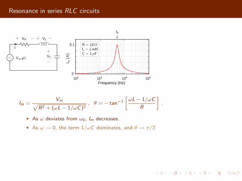
Im =Vmp
R2 + (ωL− 1/ωC)2, θ = − tan−1
»ωL− 1/ωC
R
–.
* As ω deviates from ω0, Im decreases.
* As ω → 0, the term 1/ωC dominates, and θ → π/2.
* As ω →∞, the term ωL dominates, and θ → −π/2.
(SEQUEL file: ee101 reso rlc 1.sqproj)
M. B. Patil, IIT Bombay
Resonance in series RLC circuits
I
VC
VLVR
Vm 6 0
Frequency (Hz)
0.1
0
I m(A
)
f0
105104103102
L = 1mHC = 1µF
R = 10Ω
Frequency (Hz)
f0
0
−90
90
θ(d
egre
es)
105104103102
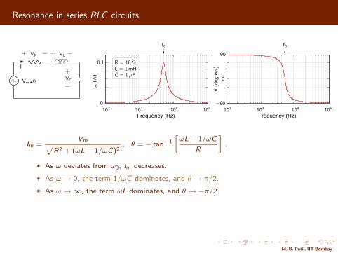
Im =Vmp
R2 + (ωL− 1/ωC)2, θ = − tan−1
»ωL− 1/ωC
R
–.
* As ω deviates from ω0, Im decreases.
* As ω → 0, the term 1/ωC dominates, and θ → π/2.
* As ω →∞, the term ωL dominates, and θ → −π/2.
(SEQUEL file: ee101 reso rlc 1.sqproj)
M. B. Patil, IIT Bombay
Resonance in series RLC circuits
I
VC
VLVR
Vm 6 0
Frequency (Hz)
0.1
0
I m(A
)
f0
105104103102
L = 1mHC = 1µF
R = 10Ω
Frequency (Hz)
f0
0
−90
90
θ(d
egre
es)
105104103102
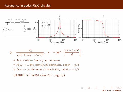
Im =Vmp
R2 + (ωL− 1/ωC)2, θ = − tan−1
»ωL− 1/ωC
R
–.
* As ω deviates from ω0, Im decreases.
* As ω → 0, the term 1/ωC dominates, and θ → π/2.
* As ω →∞, the term ωL dominates, and θ → −π/2.
(SEQUEL file: ee101 reso rlc 1.sqproj)
M. B. Patil, IIT Bombay
Resonance in series RLC circuits
I
VC
VLVR
Vm 6 0
Frequency (Hz)
0.1
0
I m(A
)
f0
105104103102
L = 1mHC = 1µF
R = 10Ω
Frequency (Hz)
f0
0
−90
90
θ(d
egre
es)
105104103102
Im =Vmp
R2 + (ωL− 1/ωC)2, θ = − tan−1
»ωL− 1/ωC
R
–.
* As ω deviates from ω0, Im decreases.
* As ω → 0, the term 1/ωC dominates, and θ → π/2.
* As ω →∞, the term ωL dominates, and θ → −π/2.
(SEQUEL file: ee101 reso rlc 1.sqproj)
M. B. Patil, IIT Bombay
Resonance in series RLC circuits
ω
I
VC
VLVR
0
Vm 6 0
Imaxm
Imaxm /
√2
ω2ω0ω1
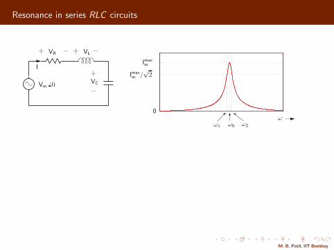
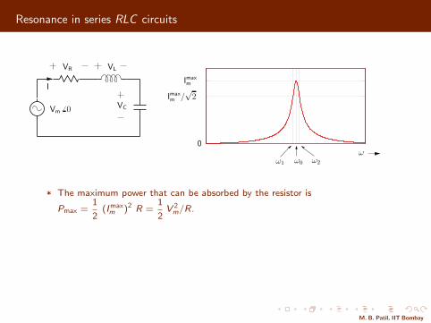
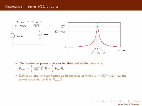
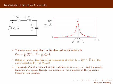
* The maximum power that can be absorbed by the resistor is
Pmax =1
2(Imax
m )2 R =1
2V 2
m/R.
* Define ω1 and ω2 (see figure) as frequencies at which Im = Imaxm /√
2, i.e., thepower absorbed by R is Pmax/2.
* The bandwidth of a resonant circuit is defined as B = ω2 − ω1, and the qualityfactor as Q = ω0/B. Quality is a measure of the sharpness of the Im versusfrequency relationship.
M. B. Patil, IIT Bombay
Resonance in series RLC circuits
ω
I
VC
VLVR
0
Vm 6 0
Imaxm
Imaxm /
√2
ω2ω0ω1
* The maximum power that can be absorbed by the resistor is
Pmax =1
2(Imax
m )2 R =1
2V 2
m/R.
* Define ω1 and ω2 (see figure) as frequencies at which Im = Imaxm /√
2, i.e., thepower absorbed by R is Pmax/2.
* The bandwidth of a resonant circuit is defined as B = ω2 − ω1, and the qualityfactor as Q = ω0/B. Quality is a measure of the sharpness of the Im versusfrequency relationship.
M. B. Patil, IIT Bombay
Resonance in series RLC circuits
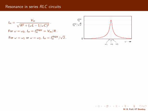
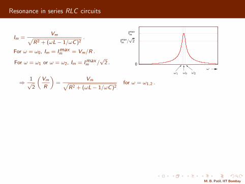
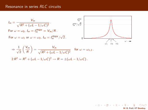
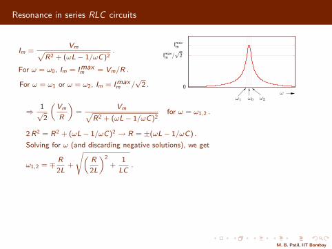
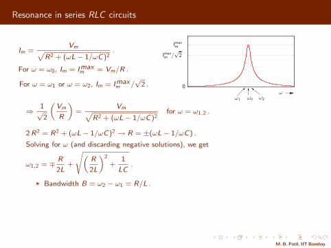
Im =Vmp
R2 + (ωL− 1/ωC)2.
For ω = ω0, Im = Imaxm = Vm/R .
For ω = ω1 or ω = ω2, Im = Imaxm /
√2 .
ω0
Imaxm
Imaxm /
√2
ω2ω0ω1
⇒ 1√2
„Vm
R
«=
VmpR2 + (ωL− 1/ωC)2
for ω = ω1,2 .
2 R2 = R2 + (ωL− 1/ωC)2 → R = ±(ωL− 1/ωC) .
Solving for ω (and discarding negative solutions), we get
ω1,2 = ∓ R
2L+
s„R
2L
«2
+1
LC.
* Bandwidth B = ω2 − ω1 = R/L .
* Quality Q = ω0/B = ω0L/R .
* Show that, at resonance (i.e., ω = ω0), |VL| = |VC | = Q Vm .
* Show that ω0 =√ω1ω2 .
M. B. Patil, IIT Bombay
Resonance in series RLC circuits
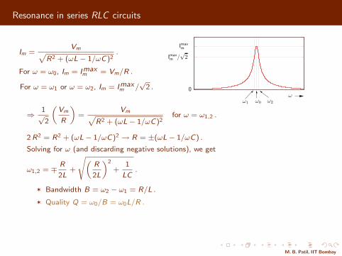
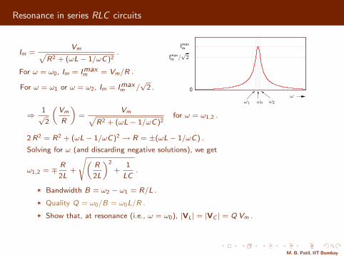
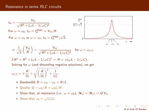
Frequency (Hz)Frequency (Hz)
I = Im 6 θ
VC
VLVR
0.1
0
I m(A
)
Vm 6 00
−90
90
θ(d
egre
es)
105105 104104 103103 102102
R = 20Ω
R = 10Ω
R = 20Ω
R = 10Ω
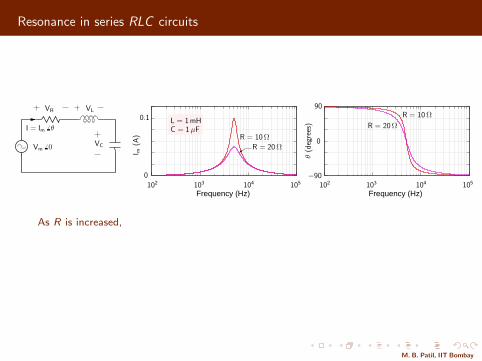
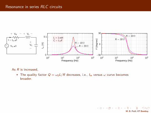
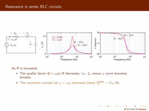
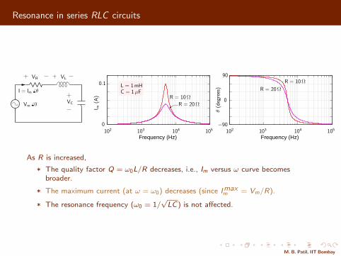
L = 1mHC = 1 µF
As R is increased,
* The quality factor Q = ω0L/R decreases, i.e., Im versus ω curve becomesbroader.
* The maximum current (at ω = ω0) decreases (since Imaxm = Vm/R).
* The resonance frequency (ω0 = 1/√
LC) is not affected.
M. B. Patil, IIT Bombay
Resonance in series RLC circuits
Frequency (Hz)Frequency (Hz)
I = Im 6 θ
VC
VLVR
0.1
0
I m(A
)
Vm 6 00
−90
90
θ(d
egre
es)
105105 104104 103103 102102
R = 20Ω
R = 10Ω
R = 20Ω
R = 10Ω
L = 1mHC = 1 µF
As R is increased,
* The quality factor Q = ω0L/R decreases, i.e., Im versus ω curve becomesbroader.
* The maximum current (at ω = ω0) decreases (since Imaxm = Vm/R).
* The resonance frequency (ω0 = 1/√
LC) is not affected.
M. B. Patil, IIT Bombay
Resonance in series RLC circuits
I
VC
VLVR
Vm 6 0
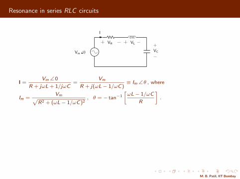
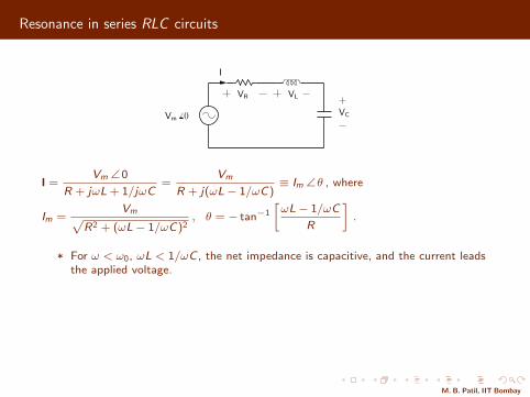
I =Vm ∠ 0
R + jωL + 1/jωC=
Vm
R + j(ωL− 1/ωC)≡ Im ∠ θ , where
Im =Vmp
R2 + (ωL− 1/ωC)2, θ = − tan−1
»ωL− 1/ωC
R
–.
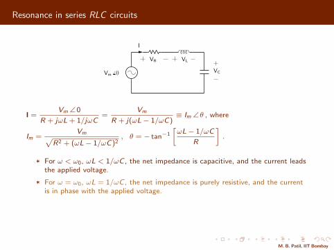
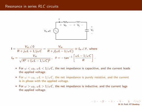
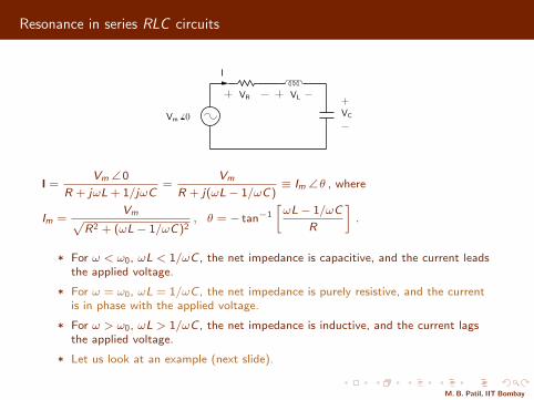
* For ω < ω0, ωL < 1/ωC , the net impedance is capacitive, and the current leadsthe applied voltage.
* For ω = ω0, ωL = 1/ωC , the net impedance is purely resistive, and the currentis in phase with the applied voltage.
* For ω > ω0, ωL > 1/ωC , the net impedance is inductive, and the current lagsthe applied voltage.
* Let us look at an example (next slide).
M. B. Patil, IIT Bombay
Resonance in series RLC circuits
I
VC
VLVR
Vm 6 0
I =Vm ∠ 0
R + jωL + 1/jωC=
Vm
R + j(ωL− 1/ωC)≡ Im ∠ θ , where
Im =Vmp
R2 + (ωL− 1/ωC)2, θ = − tan−1
»ωL− 1/ωC
R
–.
* For ω < ω0, ωL < 1/ωC , the net impedance is capacitive, and the current leadsthe applied voltage.
* For ω = ω0, ωL = 1/ωC , the net impedance is purely resistive, and the currentis in phase with the applied voltage.
* For ω > ω0, ωL > 1/ωC , the net impedance is inductive, and the current lagsthe applied voltage.
* Let us look at an example (next slide).
M. B. Patil, IIT Bombay
Resonance in series RLC circuits
0 100 200 300 400
−1
1
0
0.1
0
−0.1
−1
1
0
−1
1
0
0.1
0
−0.1
0.1
0
−0.1
Time (µsec)
i
Vs
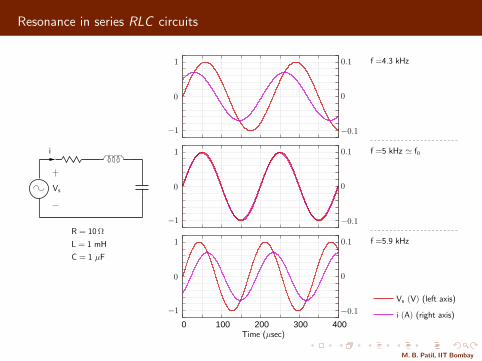
i (A) (right axis)
Vs (V) (left axis)
f =4.3 kHz
f =5 kHz ≃ f0
f =5.9 kHzR = 10Ω
L = 1 mH
C = 1 µF
M. B. Patil, IIT Bombay
Resonance in series RLC circuits: phasor diagrams
0
4
3
2
1
−1
−2
−3
−40 1 2−1 0 1 2−1 0 1 2−1
I
VC
VLVR
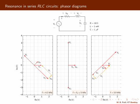
C = 1 µF
R = 10Ω
L = 1 mH
Re(V) Re(V) Re(V)
Im(V
)
Vs
VR
Vs, VR
VL
VC
Vs
VC
VC
VL
VR
VL
VR
VL
VR
Vs
f = f0 ≃ 5 kHzf = 4.3 kHz f = 5.9 kHz
VL
M. B. Patil, IIT Bombay
Resonance in parallel RLC circuits
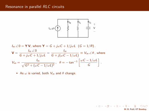
IL ICIR
VIm 6 0
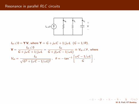
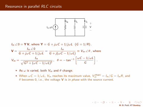
Im ∠ 0 = Y V, where Y = G + jωC + 1/jωL (G = 1/R) .
V =Im ∠ 0
G + jωC + 1/jωL=
Im
G + j(ωC − 1/ωL)≡ Vm ∠ θ , where
Vm =Imp
G2 + (ωC − 1/ωL)2, θ = − tan−1
»ωC − 1/ωL
G
–.
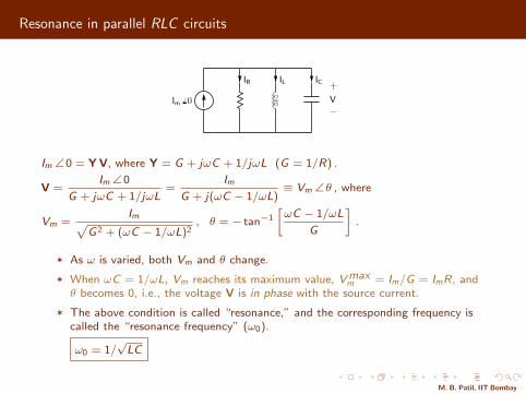
* As ω is varied, both Vm and θ change.
* When ωC = 1/ωL, Vm reaches its maximum value, Vmaxm = Im/G = ImR, and
θ becomes 0, i.e., the voltage V is in phase with the source current.
* The above condition is called “resonance,” and the corresponding frequency iscalled the “resonance frequency” (ω0).
ω0 = 1/√
LC
M. B. Patil, IIT Bombay
Resonance in parallel RLC circuits
IL ICIR
VIm 6 0
Im ∠ 0 = Y V, where Y = G + jωC + 1/jωL (G = 1/R) .
V =Im ∠ 0
G + jωC + 1/jωL=
Im
G + j(ωC − 1/ωL)≡ Vm ∠ θ , where
Vm =Imp
G2 + (ωC − 1/ωL)2, θ = − tan−1
»ωC − 1/ωL
G
–.
* As ω is varied, both Vm and θ change.
* When ωC = 1/ωL, Vm reaches its maximum value, Vmaxm = Im/G = ImR, and
θ becomes 0, i.e., the voltage V is in phase with the source current.
* The above condition is called “resonance,” and the corresponding frequency iscalled the “resonance frequency” (ω0).
ω0 = 1/√
LC
M. B. Patil, IIT Bombay
Resonance in parallel RLC circuits
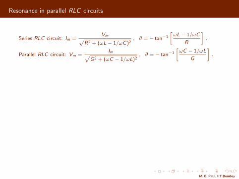
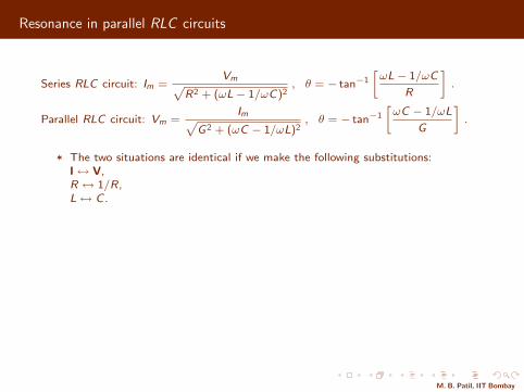
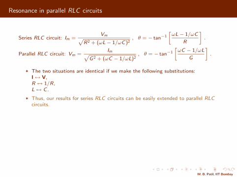
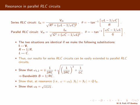
Series RLC circuit: Im =Vmp
R2 + (ωL− 1/ωC)2, θ = − tan−1
»ωL− 1/ωC
R
–.
Parallel RLC circuit: Vm =Imp
G2 + (ωC − 1/ωL)2, θ = − tan−1
»ωC − 1/ωL
G
–.
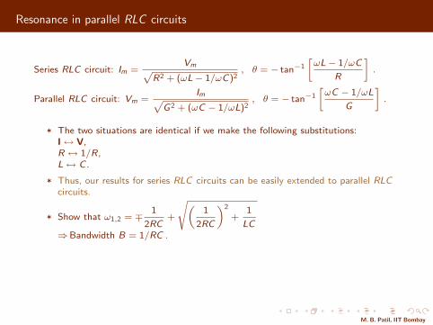
* The two situations are identical if we make the following substitutions:I↔ V,R ↔ 1/R,L↔ C .
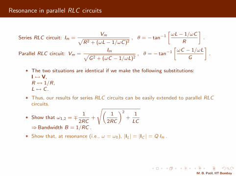
* Thus, our results for series RLC circuits can be easily extended to parallel RLCcircuits.
* Show that ω1,2 = ∓ 1
2RC+
s„1
2RC
«2
+1
LC⇒Bandwidth B = 1/RC .
* Show that, at resonance (i.e., ω = ω0), |IL| = |IC | = Q Im .
* Show that ω0 =√ω1ω2 .
M. B. Patil, IIT Bombay
Resonance in parallel RLC circuits
Series RLC circuit: Im =Vmp
R2 + (ωL− 1/ωC)2, θ = − tan−1
»ωL− 1/ωC
R
–.
Parallel RLC circuit: Vm =Imp
G2 + (ωC − 1/ωL)2, θ = − tan−1
»ωC − 1/ωL
G
–.
* The two situations are identical if we make the following substitutions:I↔ V,R ↔ 1/R,L↔ C .
* Thus, our results for series RLC circuits can be easily extended to parallel RLCcircuits.
* Show that ω1,2 = ∓ 1
2RC+
s„1
2RC
«2
+1
LC⇒Bandwidth B = 1/RC .
* Show that, at resonance (i.e., ω = ω0), |IL| = |IC | = Q Im .
* Show that ω0 =√ω1ω2 .
M. B. Patil, IIT Bombay
Resonance in parallel RLC circuits: home work
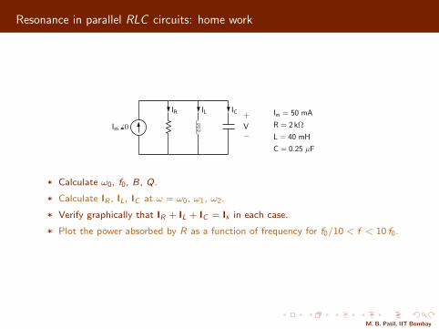
IL ICIR
VIm 6 0 R = 2 kΩ
L = 40 mH
C = 0.25 µF
Im = 50 mA
* Calculate ω0, f0, B, Q.
* Calculate IR , IL, IC at ω = ω0, ω1, ω2.
* Verify graphically that IR + IL + IC = Is in each case.
* Plot the power absorbed by R as a function of frequency for f0/10 < f < 10 f0.
M. B. Patil, IIT Bombay