ECE 201 Circuit Theory I1 Introduction to the Operational Amplifier μA 741 OP AMP.
16
ECE 201 Circuit Theory I 1 Introduction to the Operational Amplifier μA 741 OP AMP
-
date post
19-Dec-2015 -
Category
Documents
-
view
225 -
download
0
Transcript of ECE 201 Circuit Theory I1 Introduction to the Operational Amplifier μA 741 OP AMP.
ECE 201 Circuit Theory I 1
Introduction to the Operational Amplifier
μA 741 OP AMP
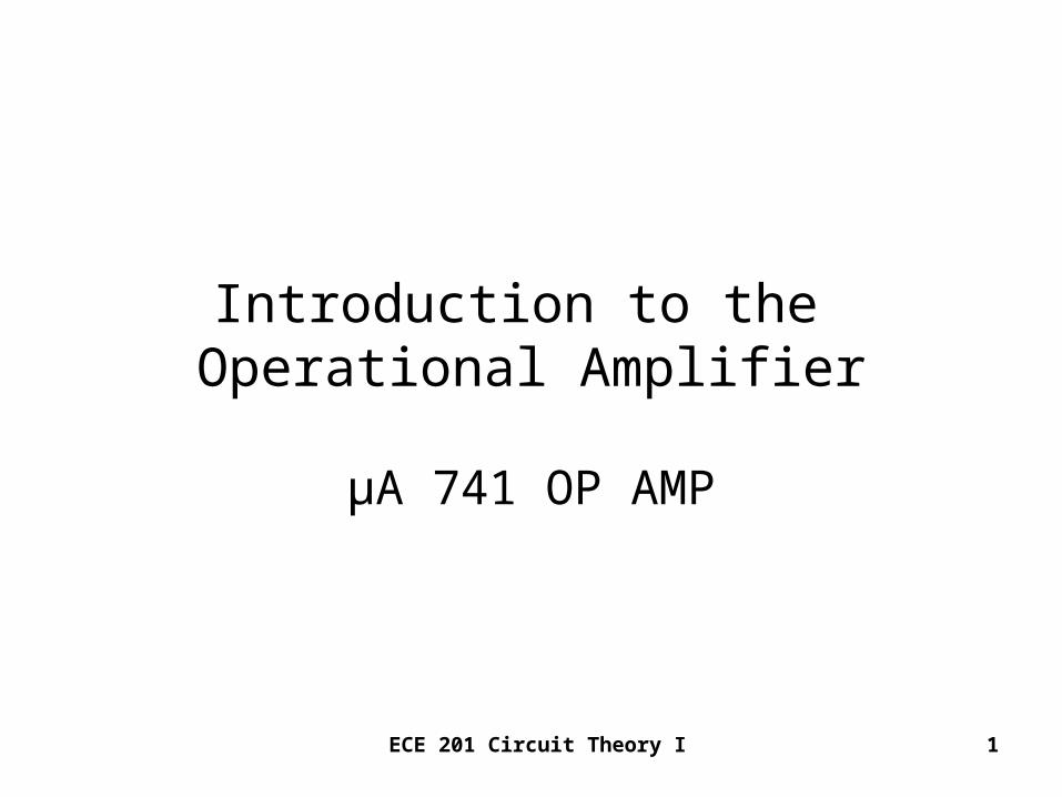
ECE 201 Circuit Theory I 2
Schematic -- 741 OP AMP
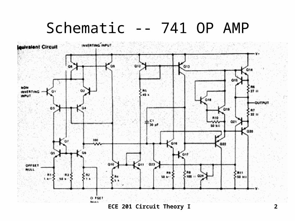
ECE 201 Circuit Theory I 3
741 OP AMP – Package & Pin Layout
•2 Inverting Input•3 Non-Inverting Input•6 Output•7 + Voltage Supply VCC
•4 – Voltage Supply VEE
•1 and 5 -- Offset Null
ECE 201 Circuit Theory I 4
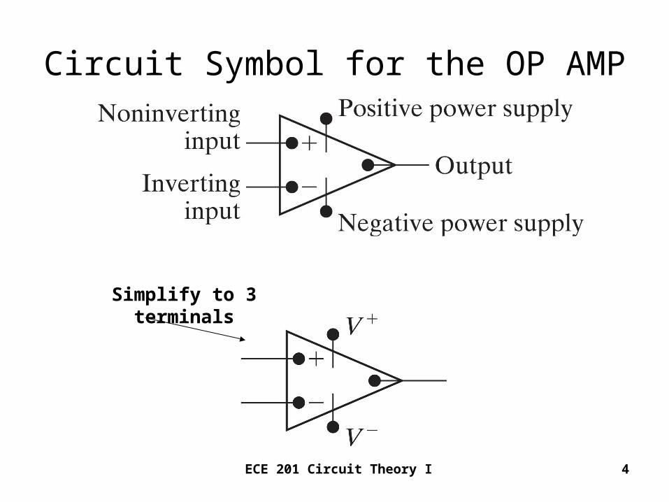
Circuit Symbol for the OP AMP
Simplify to 3 terminals

ECE 201 Circuit Theory I 5
μA 741 OP AMP – Pin Identification
• 2 Inverting Input• 3 Non-Inverting Input• 6 Output
• 7 + Voltage Supply VCC
• 4 – Voltage Supply VEE
• 1 and 5 -- Offset Null
U1
741
3
2
4
7
6
51
For simplicity, use only pins 2, 3, and 6.
ECE 201 Circuit Theory I 6
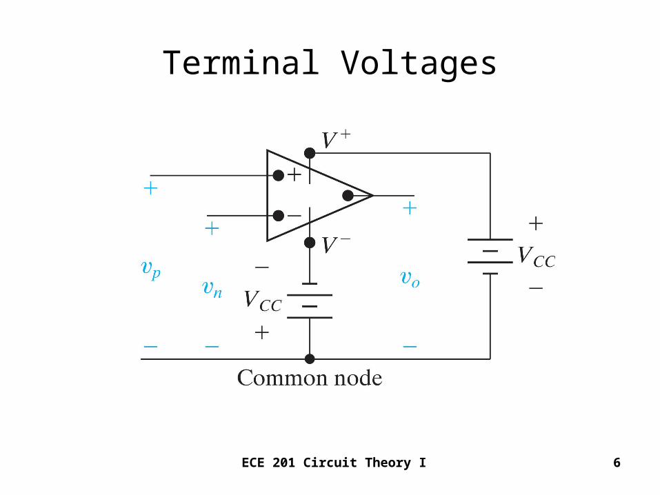
Terminal Voltages
ECE 201 Circuit Theory I 7
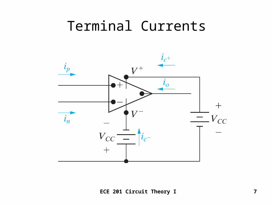
Terminal Currents
ECE 201 Circuit Theory I 8
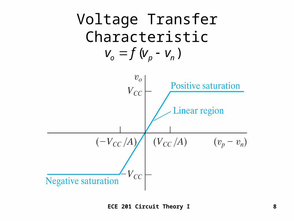
Voltage Transfer Characteristic
( )o p nv f v v
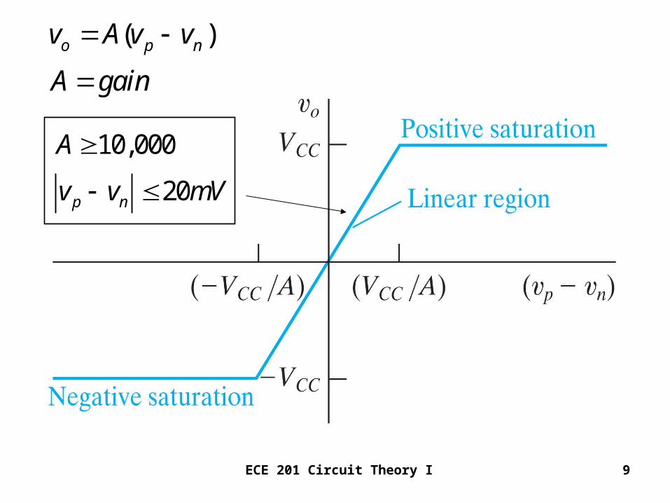
ECE 201 Circuit Theory I 9
( )o p nv A v v
A gain
10,000
20p n
A
v v mV
ECE 201 Circuit Theory I 10
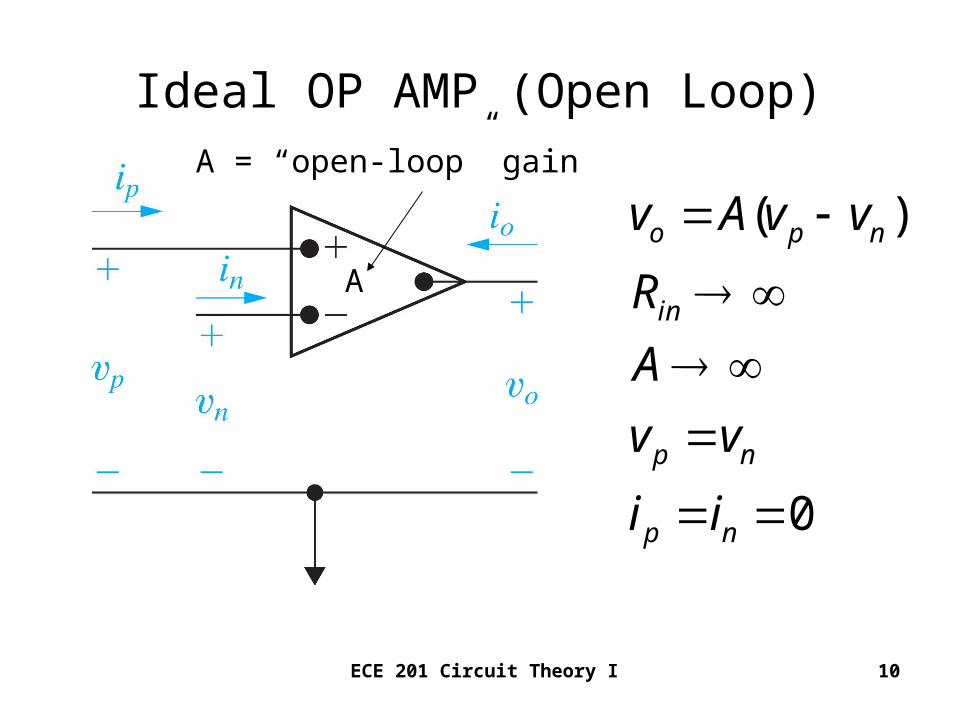
Ideal OP AMP (Open Loop)
( )
0
o p n
in
p n
p n
v A v v
R
A
v v
i i
A
A = “open-loop” gain
ECE 201 Circuit Theory I 11
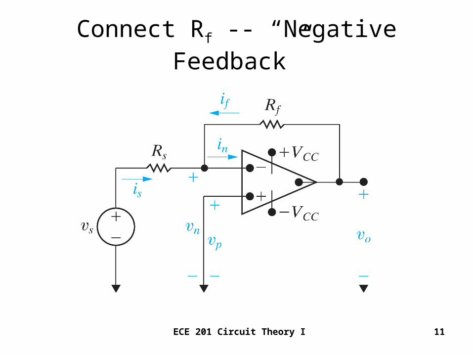
Connect Rf -- “Negative Feedback”
ECE 201 Circuit Theory I 12
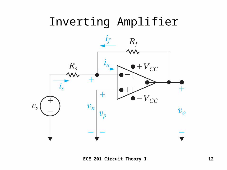
Inverting Amplifier
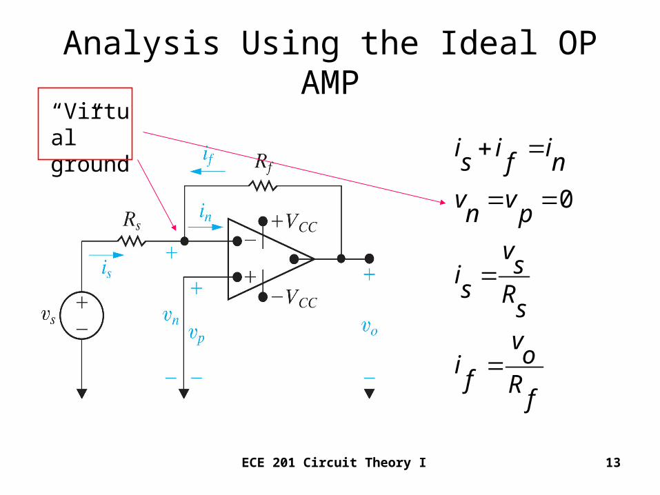
ECE 201 Circuit Theory I 13
Analysis Using the Ideal OP AMP
0
i i is f n
v vn p
vsi
s Rsvoi
f Rf
“Virtual” ground
ECE 201 Circuit Theory I 14
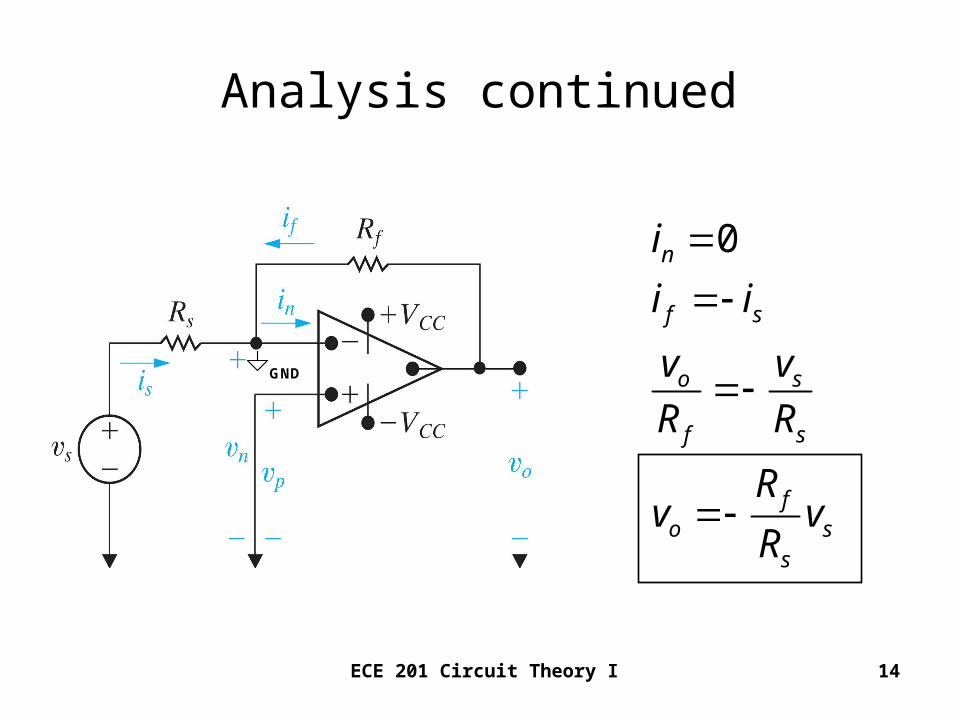
Analysis continued
0n
f s
o s
f s
fo s
s
i
i i
v v
R R
Rv v
R
GND
ECE 201 Circuit Theory I 15
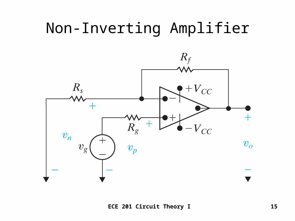
Non-Inverting Amplifier
ECE 201 Circuit Theory I 16
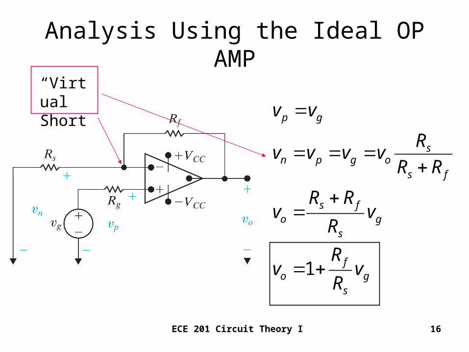
Analysis Using the Ideal OP AMP
1
p g
sn p g o
s f
s fo g
s
fo g
s
v v
Rv v v v
R R
R Rv v
R
Rv v
R
“Virtual Short


![Arithmetic of Hermitian Forms - uni-bielefeld.de · Arithmetic of Hermitian Forms 741 Then we ask, for a fixed q∈ F×,whether the set {h∈ V ϕ[h] = q modulo Γ1(L) is a finite](https://static.fdocument.org/doc/165x107/5f26eb281803a54ebe3d030b/arithmetic-of-hermitian-forms-uni-arithmetic-of-hermitian-forms-741-then-we-ask.jpg)


![[PPT]Kirchoff’s Laws - NAU jan.ucc.nau.edu web serversh295/EE188/slides/KirchoffLaws.ppt · Web viewKirchoff’s Laws Chapter 3 Example Circuit Writing KVL, I1∙14.4Ω – 50 v](https://static.fdocument.org/doc/165x107/5ab07e597f8b9ac66c8b4db2/pptkirchoffs-laws-nau-januccnauedu-web-sh295ee188slideskirchofflawspptweb.jpg)