
EAD Template V4 - TZUS
66
EOTA file № 18-12-0113-01.07 Adopted European Assessment Document according to Regulation (EU) № 305/2011, Annex II 7. European Organisation for Technical Assessment www.eota.eu EAD 120113-00-0107 August 2019 MODULAR EXPANSION JOINTS FOR ROAD BRIDGES
Transcript of EAD Template V4 - TZUS
EOTA file № 18-12-0113-01.07
Adopted European Assessment Document according to Regulation (EU) № 305/2011, Annex II 7.
European Organisation for Technical Assessment www.eota.eu
EAD 120113-00-0107
August 2019
MODULAR EXPANSION JOINTS FOR ROAD BRIDGES

European Assessment Document – EAD 120113-00-0107 3/67
©EOTA 2019
Translation of the EAD title in the following official languages of the European Union:
EOTA file No 18-12-0113-01.07
EAD Number 120113-00-0107
En - english Modular expansion joints for road bridges
bg – български
cs – čeština
da – dansk
de – deutsch Profilkonstruktionen mit mehreren Dichtelementen für Straßenbrücken
el – ελληνικά
es – español
et – eesti keel
fi – suomi
fr - français
hr – hrvatski
hu – magyar
it – italiano
lt – lietuvių kalba
lv – latviešu valoda
mt – malti
nl – nederlands
pl – polski
pt – português
ro – română
sk – slovenčina
sl – slovenščina
sv – svenska
no - norsk
is - íslenskur
The reference title and language for this EAD is English. The applicable rules of copyright refer to the document elaborated in and
published by EOTA.
This European Assessment Document (EAD) has been developed taking into account up-to-date technical and scientific knowledge
at the time of issue and is published in accordance with the relevant provisions of Regulation (EU) No 305/2011 as a basis for the
preparation and issuing of European Technical Assessments (ETA).
European Assessment Document – EAD 120113-00-0107 4/67
©EOTA 2019
Contents
1 Scope of the EAD ........................................................................................................................... 6
1.1 Description of the construction product 6
1.2 Information on the intended use(s) of the construction product 7 1.2.1 Intended use(s) ...................................................................................................................... 7 1.2.2 Working life/Durability ............................................................................................................ 7
1.3 Specific terms used in this EAD (if necessary in addition to the definitions in CPR, Art 2) 8 1.3.1 Single crossbeam modular expansion joints ......................................................................... 9 1.3.2 Multiple crossbeam modular expansion joints ...................................................................... 9 1.3.3 Transition strip ....................................................................................................................... 9 1.3.4 Secondary elements .............................................................................................................. 9 1.3.5 Batch ..................................................................................................................................... 9 1.3.6 Gap ........................................................................................................................................ 9 1.3.7 Kerb ..................................................................................................................................... 10 1.3.8 Movement capacity.............................................................................................................. 10 1.3.9 Replaceability ...................................................................................................................... 10 1.3.10 Skew angle (of the expansion joint) .................................................................................... 11 1.3.11 Void ..................................................................................................................................... 11 1.3.12 Traffic noise reducing elements .......................................................................................... 11
2 Essential characteristics and relevant assessment methods and criteria ............................ 12
2.1 Essential characteristics of the product 12
2.2 Methods and criteria for assessing the performance of the product in relation to essential characteristics of the product 13
2.2.1 Mechanical resistance ......................................................................................................... 13 2.2.2 Resistance to fatigue ........................................................................................................... 18 2.2.3 Seismic behaviour ............................................................................................................... 20 2.2.4 Movement capacity.............................................................................................................. 20 2.2.5 Cleanability .......................................................................................................................... 21 2.2.6 Resistance to wear .............................................................................................................. 22 2.2.7 Watertightness ..................................................................................................................... 22 2.2.8 Durability .............................................................................................................................. 23 2.2.9 Content, emission and/or release of dangerous substances .............................................. 25 2.2.10 Ability to bridge gaps and levels in the running surface ...................................................... 25 2.2.11 Skid resistance .................................................................................................................... 27 2.2.12 Drainage capacity ................................................................................................................ 28
3 Assessment and verification of constancy of performance ................................................... 28
3.1 System(s) of assessment and verification of constancy of performance to be applied 28
3.2 Tasks of the manufacturer 28
3.3 Tasks of the notified body 36
4 Reference documents ................................................................................................................. 37
Annex A – Typical designs of modular expansion joints ..................................................................... 41
Annex B – Components for modular expansion joints ........................................................................ 46
Annex C – Static testing – Mechanical resistance of the product represented by test method for components .............................................................................................................................................. 51
Annex D – Dynamic testing – Resistance to fatigue and wear of the product represented by components .............................................................................................................................................. 54

European Assessment Document – EAD 120113-00-0107 5/67
©EOTA 2019
Annex E - Dynamic assessment and field testing ................................................................................ 57
Annex F – Fixing of sealing element represented by test method for components ......................... 67

European Assessment Document – EAD 120113-00-0107 6/67
©EOTA 2019
1 SCOPE OF THE EAD
1.1 Description of the construction product
This EAD covers modular expansion joints for road bridges.
Modular expansion joints for road bridges are used to ensure the continuity of the running surface as well as bearing capacity and the movement of the bridges whatever the nature of the material of the bridge structure.
Expansion joints for moveable bridges are not covered by this EAD.
While listed in the traffic direction, the modular expansion joints consist of a succession of edge beams, watertight elements (sealing element), movement controlled metal beams (centre beams), supported by moveable substructures bridging the structural gap (i.e. cross beams, cantilevers or pantographs). The metal beams are flush with the running surface. The assembly of watertight elements, centre beams and substructures is situated between edge beams, rigidly and in a watertight manner connected to the main structure. The top surfaces of the centre beams and edge beams are flush with the running surface. Where sealing elements are flush with the running surface, they are not designed to carry the traffic loads. The anchorage system of the modular expansion joint is part of the kit.
This EAD applies to modular expansion joint kits for which the components and related performances are defined in Annex B in order to ensure proper functioning of the expansion joint kit.
The modular expansion joint is component based. Exact description of components is included in the ETA.
Optional components (e.g. transition strip, special adaptation for cyclists or pedestrian, drainage device made of aluminium or stainless steel (according to EAD 120109-00-0107, Annex D, Figure D.11), cantilever parts made of metal (e.g. traffic noise reducing elements)), if part of the kit to be assessed, shall be addressed in the ETA. Such optional components are not intended to increase the movement capacity. A transition strip according to this EAD is made of thermosetting or thermoplastics binder (as defined in EN ISO 472) or made of bituminous mixture or made of ready mixed concrete or resin mortar and may be part of the product to be assessed and subject of the ETA.
Annex A shows examples of typical cross sections and plan views of modular expansion joints.
The material used for connecting the joint to the substructure (e.g. concrete for recess filling and reinforcement in case of concrete bridges) considered in the assessment of the product shall be described in the ETA but is not forming a part of the product covered by the ETA.
Modular expansion joints according to this EAD are related to the atmospheric corrosivity categories C4 or C5 according to EN ISO 9223, whereas durability classes according to EN ISO 12944-1 and EN ISO 14713-1 respectively apply.
This EAD applies for products with the following corrosion protection aspects:
- Structural steel surfaces in contact with concrete have no coating. Only at the transitions an overlap of approximately 50 mm of the full corrosion protection system is applied.
- In case of use of stainless steel for components, the steel type is selected under consideration of the corrosivity categories of the atmosphere using the conditions given in EN 1993-1-4, Annex A, A.2, A.4 and A.5.
- Aluminium alloys have a corrosion resistance of at least category “B” according to EN 1999-1-1, Table D1, or equivalent. Furthermore, interaction between concrete and the aluminium alloy is prevented.
- Permanent steel bolts are at least electrolytic zinc plated. For coating with Fe/Zn 25 EN ISO 2081 applies, for hot dip galvanisation EN ISO 10684 applies. In case of stainless steel EN ISO 3506-1 applies, whereas EN 1993-1-4, Annex A, A.2, A.4 and A.5 needs to be considered. In addition for high strength friction grip bolts, the contact surfaces of steel plates and splices in “High Strength Friction Grip Bolt Connections” are executed according to EN 1090-2.
- Sliding surfaces made of austenitic steel do not have a corrosion protection system.
The product is not covered by a harmonised European standard (hEN).

European Assessment Document – EAD 120113-00-0107 7/67
©EOTA 2019
Concerning product packaging, transport, storage, maintenance, replacement and repair it is the responsibility of the manufacturer to undertake the appropriate measures and to advise his clients on the transport, storage, maintenance, replacement and repair of the product as he considers necessary.
It is assumed that the product will be installed according to the manufacturer’s instructions or (in absence of such instructions) according to the usual practice of the building professionals.
Relevant manufacturer’s stipulations having influence on the performance of the product covered by this European Assessment Document shall be considered for the determination of the performance and detailed in the ETA.
1.2 Information on the intended use(s) of the construction product
1.2.1 Intended use(s)
The product according to this EAD is intended to be used for road bridges.
1.2.1.1 Operating temperature categories
The operating temperature is defined as the shade air temperature according to EN 1991-1-5, Clause 1.5.2.
The product according to this EAD is intend to be used under operating temperatures given below:
- Levels of minimum operating temperature categories: -10 °C, -20 °C, -30 °C, -40 °C - Levels of maximum operating temperature categories: +35 °C, +45 °C
Operating temperature shall be stated in the ETA.
1.2.1.2 Use categories
The use categories to be stated in the ETA are specified with regard to the user and action categories.
1.2.1.2.1 User categories
- Vehicle - Cyclist - Pedestrian
1.2.1.2.2 Actions categories
- Standard action (traffic load action) - Optional action (accidental effects of heavy wheel on footpath, seismic phenomena; wheel shock
on the upstand)
Actions are defined in EAD 120109-00-0107, Annex D, Clause D.2.3 and D.2.4.
1.2.2 Working life/Durability
The assessment methods included or referred to in this EAD have been written based on the manufacturer’s request to take into account a working life of the modular expansion joint for the intended use according to the working life categories as given in Table 1 when installed in the works (provided that the modular expansion joint is subject to appropriate installation (see 1.1)). These provisions are based upon the current state of the art and the available knowledge and experience.
The intended working life of the kit is based on the following working life categories, with Nobs = 0,5 million/year or (see EN 1991-2, Table 4.5 and EAD 120109-00-0107, Annex D, Clause D.2.3.3).
European Assessment Document – EAD 120113-00-0107 8/67
©EOTA 2019
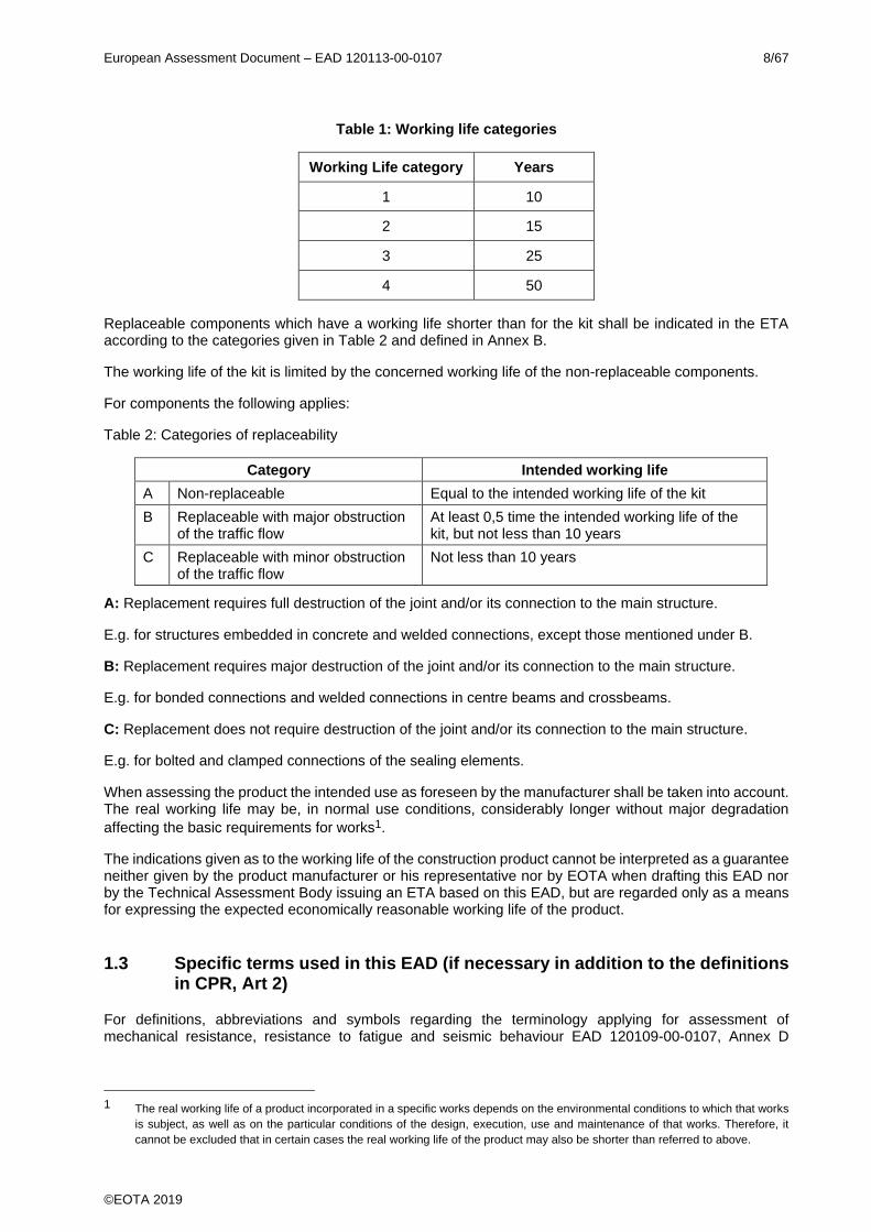
Table 1: Working life categories
Working Life category Years
1 10
2 15
3 25
4 50
Replaceable components which have a working life shorter than for the kit shall be indicated in the ETA according to the categories given in Table 2 and defined in Annex B.
The working life of the kit is limited by the concerned working life of the non-replaceable components.
For components the following applies:
Table 2: Categories of replaceability
Category Intended working life
A Non-replaceable Equal to the intended working life of the kit
B Replaceable with major obstruction of the traffic flow
At least 0,5 time the intended working life of the kit, but not less than 10 years
C Replaceable with minor obstruction of the traffic flow
Not less than 10 years
A: Replacement requires full destruction of the joint and/or its connection to the main structure.
E.g. for structures embedded in concrete and welded connections, except those mentioned under B.
B: Replacement requires major destruction of the joint and/or its connection to the main structure.
E.g. for bonded connections and welded connections in centre beams and crossbeams.
C: Replacement does not require destruction of the joint and/or its connection to the main structure.
E.g. for bolted and clamped connections of the sealing elements.
When assessing the product the intended use as foreseen by the manufacturer shall be taken into account. The real working life may be, in normal use conditions, considerably longer without major degradation
affecting the basic requirements for works1.
The indications given as to the working life of the construction product cannot be interpreted as a guarantee neither given by the product manufacturer or his representative nor by EOTA when drafting this EAD nor by the Technical Assessment Body issuing an ETA based on this EAD, but are regarded only as a means for expressing the expected economically reasonable working life of the product.
1.3 Specific terms used in this EAD (if necessary in addition to the definitions in CPR, Art 2)
For definitions, abbreviations and symbols regarding the terminology applying for assessment of mechanical resistance, resistance to fatigue and seismic behaviour EAD 120109-00-0107, Annex D
1 The real working life of a product incorporated in a specific works depends on the environmental conditions to which that works
is subject, as well as on the particular conditions of the design, execution, use and maintenance of that works. Therefore, it
cannot be excluded that in certain cases the real working life of the product may also be shorter than referred to above.
European Assessment Document – EAD 120113-00-0107 9/67
©EOTA 2019
applies. For additional terms and definitions specific for this EAD, see below. For remaining definitions see Annex B.
1.3.1 Single crossbeam modular expansion joints
Modular expansion joint where each cross beam is connected to all centre beams (for crossbeam and centre beam see Annex B.1).
1.3.2 Multiple crossbeam modular expansion joints
Modular expansion joint where each cross beam is connected to only one centre beam (for crossbeam and centre beam see Annex B.1).
1.3.3 Transition strip
Material between the expansion joint and the adjacent surfacing.
1.3.4 Secondary elements
Components of the kit not contributing to mechanical resistance and stability of the kit.
1.3.5 Batch
Quantity of product or components manufactured to the same specification within a determined period.
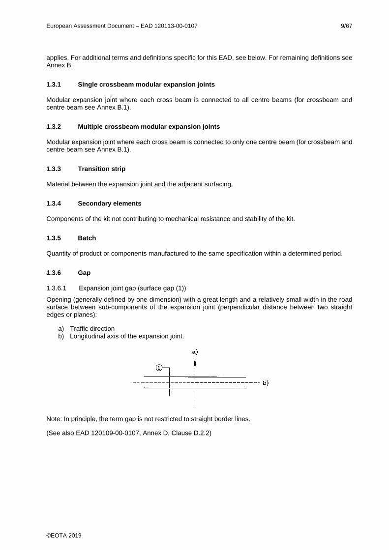
1.3.6 Gap
1.3.6.1 Expansion joint gap (surface gap (1))
Opening (generally defined by one dimension) with a great length and a relatively small width in the road surface between sub-components of the expansion joint (perpendicular distance between two straight edges or planes):
a) Traffic direction b) Longitudinal axis of the expansion joint.
Note: In principle, the term gap is not restricted to straight border lines.
(See also EAD 120109-00-0107, Annex D, Clause D.2.2)
European Assessment Document – EAD 120113-00-0107 10/67
©EOTA 2019
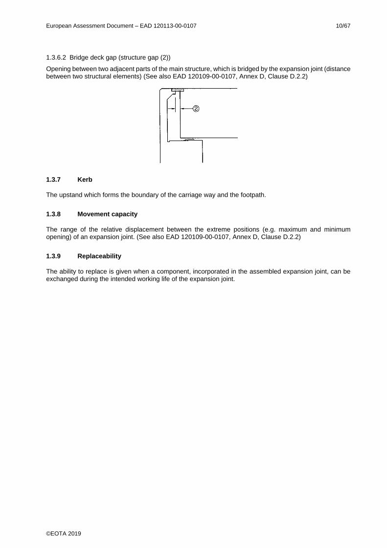
1.3.6.2 Bridge deck gap (structure gap (2))
Opening between two adjacent parts of the main structure, which is bridged by the expansion joint (distance between two structural elements) (See also EAD 120109-00-0107, Annex D, Clause D.2.2)
1.3.7 Kerb
The upstand which forms the boundary of the carriage way and the footpath.
1.3.8 Movement capacity
The range of the relative displacement between the extreme positions (e.g. maximum and minimum opening) of an expansion joint. (See also EAD 120109-00-0107, Annex D, Clause D.2.2)
1.3.9 Replaceability
The ability to replace is given when a component, incorporated in the assembled expansion joint, can be exchanged during the intended working life of the expansion joint.
European Assessment Document – EAD 120113-00-0107 11/67
©EOTA 2019
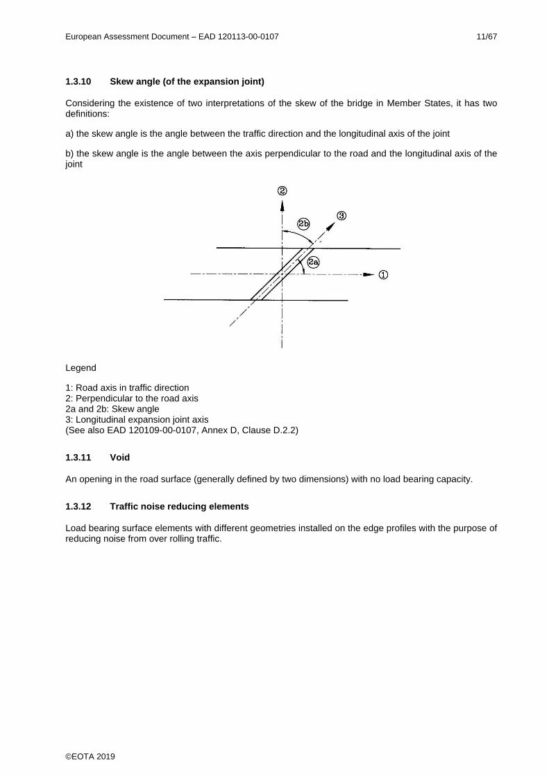
1.3.10 Skew angle (of the expansion joint)
Considering the existence of two interpretations of the skew of the bridge in Member States, it has two definitions:
a) the skew angle is the angle between the traffic direction and the longitudinal axis of the joint
b) the skew angle is the angle between the axis perpendicular to the road and the longitudinal axis of the joint
Legend
1: Road axis in traffic direction 2: Perpendicular to the road axis 2a and 2b: Skew angle 3: Longitudinal expansion joint axis (See also EAD 120109-00-0107, Annex D, Clause D.2.2)
1.3.11 Void
An opening in the road surface (generally defined by two dimensions) with no load bearing capacity.
1.3.12 Traffic noise reducing elements
Load bearing surface elements with different geometries installed on the edge profiles with the purpose of reducing noise from over rolling traffic.

European Assessment Document – EAD 120113-00-0107 12/67
©EOTA 2019
2 ESSENTIAL CHARACTERISTICS AND RELEVANT ASSESSMENT METHODS AND CRITERIA
All undated references to standards or to EADs in this chapter are to be understood as references to the dated versions listed in Clause 4.
2.1 Essential characteristics of the product
Table 3 shows how the performance of modular expansion joints is assessed in relation to the essential characteristics.
Table 3 Essential characteristics of the product and methods and criteria for assessing the performance of the product in relation to those essential characteristics
No Essential characteristic Assessment method Type of expression of product performance
Basic Works Requirement 1: Mechanical resistance and stability
1 Mechanical resistance Clause 2.2.1 Description
2 Resistance to fatigue Clause 2.2.2 Description
3 Seismic behaviour Clause 2.2.3 Description
Level
4 Movement capacity Clause 2.2.4 Level
5 Cleanability Clause 2.2.5 Description
6 Resistance to wear Clause 2.2.6 Description
7 Watertightness Clause 2.2.7 Description
8 Durability Clause 2.2.8 Description
Basic Works Requirement 3: Hygiene, health and the environment
9 Content, emission and/or release of dangerous substances
Clause 2.2.9 Level
Description
Basic Works Requirement 4: Safety and accessibility in use
10 Ability to bridge gaps and levels in the running surface
Clause 2.2.10 Level
11 Skid resistance Clause 2.2.11 Level
12 Drainage capacity Clause 2.2.12 Level

European Assessment Document – EAD 120113-00-0107 13/67
©EOTA 2019
2.2 Methods and criteria for assessing the performance of the product in relation to essential characteristics of the product
2.2.1 Mechanical resistance
Assessing the mechanical resistance of the modular expansion joint shall not lead to:
- collapse of the whole or a part of the works - major deformations to an inadmissible degree - damage by an event to an extent disproportionate to the original cause
Assessment shall be based on:
- Relevant load distribution and load model according to EAD 120109-00-0107, Annex D, Clause D.2 - Actions (according to Clause 1.2.1.2.2) considered according to EAD 120109-00-0107, Annex D,
Clause D.2.3 and D.2.4 - Safety factors used and assessment criteria according to Table 4
Calculations shall be done according to the conditions in the Eurocodes mentioned thereafter as far as relevant due to materials used and shall include information on calculation models used, whereas conditions and criteria defined thereafter shall be considered. Input from testing for calculation shall be introduced in the calculation, where relevant.
In case of testing, either in addition to or instead of calculation, as defined in the sub clauses thereafter, relevant components/assembled kit shall be referred to.
Assessment criteria used and based on the detailing thereafter shall be defined for the calculation.
In the ETA the assessment shall be stated in terms of description for the relevant product to be addressed (dimensions, materials, welds or bolted connections etc.).
Conditions for the assessment shall be stated in the ETA as far as relevant:
- Anchor forces for load distribution to the adjacent parts of the expansion joint - the load models - adjustment factors - load factors - combination factors
Whereas:
External loads on expansion joints are generated by traffic. Further loads on expansion joints may be generated as internal loads from imposed deformations or displacements or change of temperature of the joint itself.
Table 4 gives details on the assessment criteria for concerned limit state.
European Assessment Document – EAD 120113-00-0107 14/67
©EOTA 2019
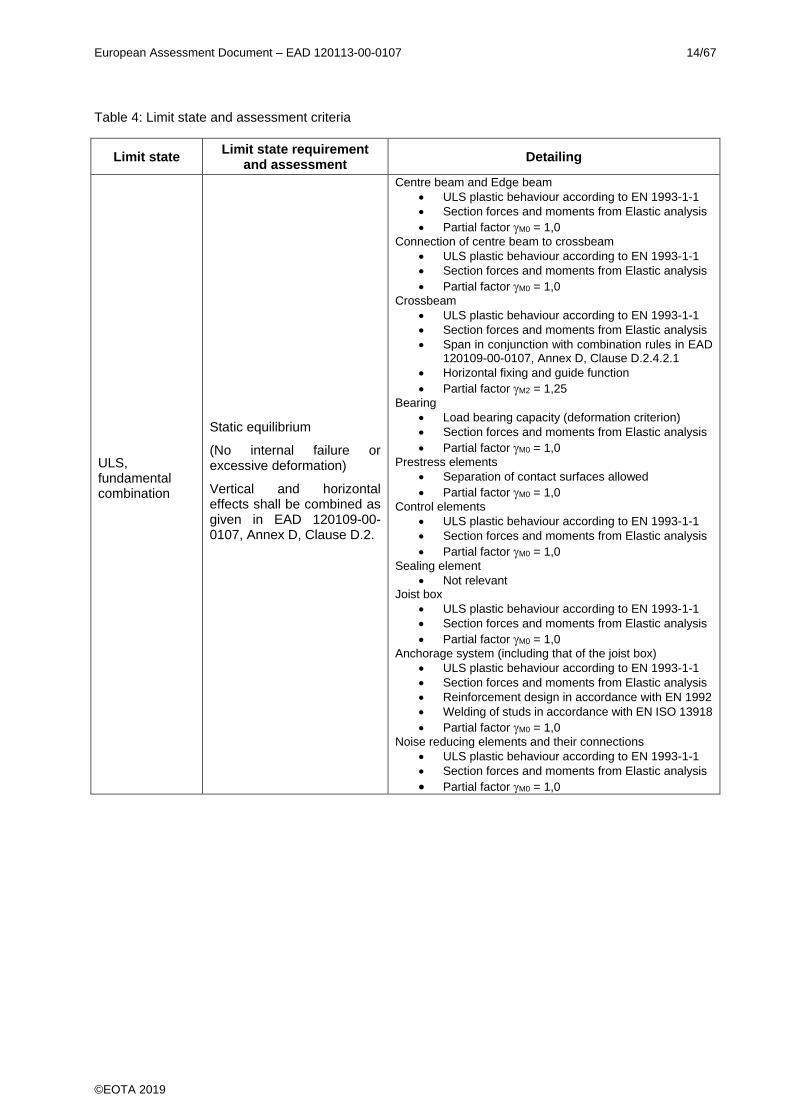
Table 4: Limit state and assessment criteria
Limit state Limit state requirement
and assessment Detailing
ULS, fundamental combination
Static equilibrium
(No internal failure or excessive deformation)
Vertical and horizontal effects shall be combined as given in EAD 120109-00-0107, Annex D, Clause D.2.
Centre beam and Edge beam
• ULS plastic behaviour according to EN 1993-1-1
• Section forces and moments from Elastic analysis
• Partial factor M0 = 1,0
Connection of centre beam to crossbeam
• ULS plastic behaviour according to EN 1993-1-1
• Section forces and moments from Elastic analysis
• Partial factor M0 = 1,0
Crossbeam
• ULS plastic behaviour according to EN 1993-1-1
• Section forces and moments from Elastic analysis
• Span in conjunction with combination rules in EAD 120109-00-0107, Annex D, Clause D.2.4.2.1
• Horizontal fixing and guide function
• Partial factor M2 = 1,25
Bearing
• Load bearing capacity (deformation criterion)
• Section forces and moments from Elastic analysis
• Partial factor M0 = 1,0
Prestress elements
• Separation of contact surfaces allowed
• Partial factor M0 = 1,0
Control elements
• ULS plastic behaviour according to EN 1993-1-1
• Section forces and moments from Elastic analysis
• Partial factor M0 = 1,0
Sealing element
• Not relevant Joist box
• ULS plastic behaviour according to EN 1993-1-1
• Section forces and moments from Elastic analysis
• Partial factor M0 = 1,0
Anchorage system (including that of the joist box)
• ULS plastic behaviour according to EN 1993-1-1
• Section forces and moments from Elastic analysis
• Reinforcement design in accordance with EN 1992
• Welding of studs in accordance with EN ISO 13918
• Partial factor M0 = 1,0
Noise reducing elements and their connections
• ULS plastic behaviour according to EN 1993-1-1
• Section forces and moments from Elastic analysis
• Partial factor M0 = 1,0
European Assessment Document – EAD 120113-00-0107 15/67
©EOTA 2019
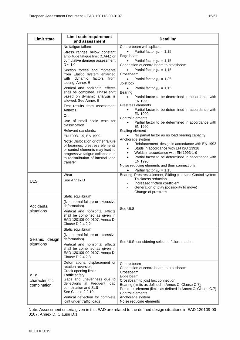
Limit state Limit state requirement
and assessment Detailing
No fatigue failure
Stress ranges below constant amplitude fatigue limit (CAFL) or cumulative damage assessment D < 1,0
Section forces and moments from Elastic system enlarged with dynamic factors from testing, Annex E
Vertical and horizontal effects shall be combined. Phase shift based on dynamic analysis is allowed. See Annex E
Test results from assessment Annex D
Or:
Use of small scale tests for classification
Relevant standards:
EN 1993-1-9, EN 1999
Note: Dislocation or other failure of bearings, prestress elements or control elements may lead to progressive fatigue collapse due to redistribution of internal load transfer
Centre beam with splices
• Partial factor Mf = 1,15
Edge beam
• Partial factor Mf = 1,15
Connection of centre beam to crossbeam
• Partial factor Mf = 1,15
Crossbeam
• Partial factor Mf = 1,35
Joist box
• Partial factor Mf = 1,15
Bearing
• Partial factor to be determined in accordance with EN 1990
Prestress elements
• Partial factor to be determined in accordance with EN 1990
Control elements
• Partial factor to be determined in accordance with EN 1990
Sealing element
• No partial factor as no load bearing capacity Anchorage system
• Reinforcement design in accordance with EN 1992
• Studs in accordance with EN ISO 13918
• Welds in accordance with EN 1993-1-9
• Partial factor to be determined in accordance with EN 1990
Noise reducing elements and their connections
• Partial factor Mf = 1,15
ULS
Wear
See Annex D
Bearing, Prestress element, Sliding plate and Control system - Thickness reduction - Increased friction coefficient - Generation of play (possibility to move)
- Change of prestress
Accidental situations
Static equilibrium
(No internal failure or excessive deformation).
Vertical and horizontal effects shall be combined as given in EAD 120109-00-0107, Annex D, Clause D.2.4.2.2
See ULS
Seismic design situations
Static equilibrium
(No internal failure or excessive deformation).
Vertical and horizontal effects shall be combined as given in EAD 120109-00-0107, Annex D, Clause D.2.4.2.3
See ULS, considering selected failure modes
SLS, characteristic combination
Deformations, displacement or rotation reversible Crack opening limits Traffic safety Gaps and unevenness due to deflections at Frequent load combination and SLS See Clause 2.2.10
Vertical deflection for complete joint under traffic loads
Centre beam Connection of centre beam to crossbeam Crossbeam Edge beam Crossbeam to joist box connection Bearing (limits as defined in Annex C, Clause C.7) Prestress element (limits as defined in Annex C, Clause C.7) Control elements Anchorage system Noise reducing elements
Note: Assessment criteria given in this EAD are related to the defined design situations in EAD 120109-00-0107, Annex D, Clause D.1.

European Assessment Document – EAD 120113-00-0107 16/67
©EOTA 2019
The skew angle between the traffic direction and the longitudinal axis of the joint influences the load transfer and shall be considered.
The support of the pavement by the joist boxes and other plate elements acting as a steel deck shall have sufficient stiffness to prevent damage to the pavement. This is achieved when the deflection under SLS loads does not exceed 0,0025 x l or 0,0025 x b, where l and b are the spans for simply supported plates and 0,005 x l, where l is the length of the cantilevering part.
For rectangular plates supported by four edges, the smallest value for b and l applies; for plates supported by three edges, the smaller value for the simple span or the cantilever applies.
The vertical deflection of load carrying elements due to characteristic traffic loads, in accordance with EAD 120109-00-0107, Annex D equation [D.13], shall not be greater than 5 mm.
The actions, loads and combination of loads and opening positions to be used for assessment in relation to the user and actions categories described in Clause 1.2.1.2 are given in EAD 120109-00-0107, Annex D, Clause D.2.
Assessment of the minimum operating temperature according to Clause 1.2.1.1 for metallic components of the kit is done according to EN 1993-1-10, Table 2.1.
For load distribution EAD 120109-00-0107, Annex D, Figure D.2 applies.
Where a sloped main structure has bearings which are moving in the horizontal plane, the slope of the expansion joint may deviate from the slope of the running surface of the main structure. The maximum slope occurring on the expansion joint surface shall be considered for assessment.
Mechanical resistance shall be assessed by calculations, testing or a combination of both. If calculation is not possible, testing according to Clause 2.2.1.2 applies.
The design loads shall be derived from the traffic loads given in EAD 120109-00-0107, Annex D, Clause D.2.
Modular expansion joints shall be calculated using common engineering principles. The calculation procedures shall be calibrated with dynamic field measurements (see Annex E).
In case of cantilever parts as defined in Clause 1.1, contributing to the mechanical resistance, for the load distribution, the conditions given in EAD 120109-00-0107, Annex D, Figure D.2, upper right sketch, apply.
The following details used for assessment shall be described in the ETA (as far as relevant):
- Fulfilment of the requirements given in Table 4 - Anchor forces for load distribution to the adjacent parts of the expansion joint shall be stated in the ETA - the load models - adjustment factors - load factors - combination factors
2.2.1.1 Calculations
Models used for calculation shall take into account relevant boundary conditions (e.g. actions, operating temperature, opening of the joint).
The partial factors M shall be taken from Table 4 or determined either:
- in accordance with 6.3 of EN 1990 and, - where relevant, using the recommended values given in the relevant Eurocode stated below,
related to the materials.
In the ETA it shall be stated in terms of description that the product fulfils the mechanical resistance for the
designs stated in the ETA and the partial factor M values used for assessment shall be stated in the ETA.
European Assessment Document – EAD 120113-00-0107 17/67
©EOTA 2019
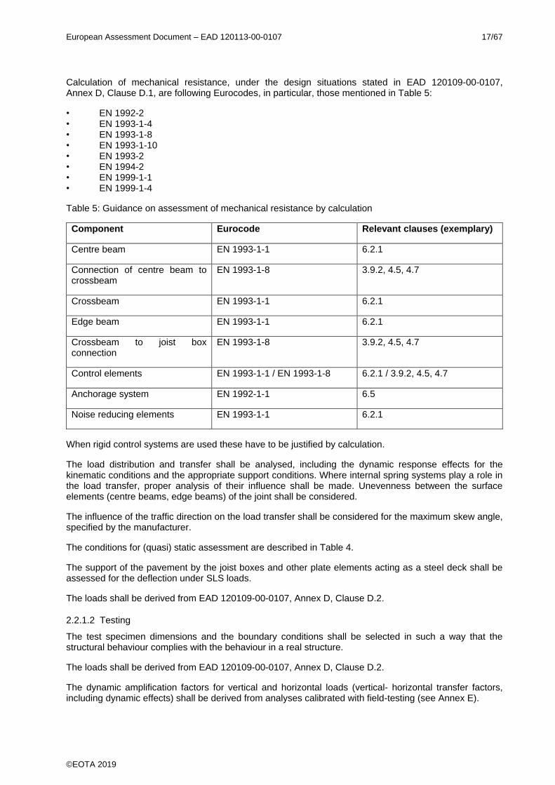
Calculation of mechanical resistance, under the design situations stated in EAD 120109-00-0107, Annex D, Clause D.1, are following Eurocodes, in particular, those mentioned in Table 5:
• EN 1992-2 • EN 1993-1-4 • EN 1993-1-8 • EN 1993-1-10 • EN 1993-2 • EN 1994-2 • EN 1999-1-1 • EN 1999-1-4
Table 5: Guidance on assessment of mechanical resistance by calculation
Component Eurocode Relevant clauses (exemplary)
Centre beam EN 1993-1-1 6.2.1
Connection of centre beam to crossbeam
EN 1993-1-8 3.9.2, 4.5, 4.7
Crossbeam EN 1993-1-1 6.2.1
Edge beam EN 1993-1-1 6.2.1
Crossbeam to joist box connection
EN 1993-1-8 3.9.2, 4.5, 4.7
Control elements EN 1993-1-1 / EN 1993-1-8 6.2.1 / 3.9.2, 4.5, 4.7
Anchorage system EN 1992-1-1 6.5
Noise reducing elements EN 1993-1-1 6.2.1
When rigid control systems are used these have to be justified by calculation.
The load distribution and transfer shall be analysed, including the dynamic response effects for the kinematic conditions and the appropriate support conditions. Where internal spring systems play a role in the load transfer, proper analysis of their influence shall be made. Unevenness between the surface elements (centre beams, edge beams) of the joint shall be considered.
The influence of the traffic direction on the load transfer shall be considered for the maximum skew angle, specified by the manufacturer.
The conditions for (quasi) static assessment are described in Table 4.
The support of the pavement by the joist boxes and other plate elements acting as a steel deck shall be assessed for the deflection under SLS loads.
The loads shall be derived from EAD 120109-00-0107, Annex D, Clause D.2.
2.2.1.2 Testing
The test specimen dimensions and the boundary conditions shall be selected in such a way that the structural behaviour complies with the behaviour in a real structure.
The loads shall be derived from EAD 120109-00-0107, Annex D, Clause D.2.
The dynamic amplification factors for vertical and horizontal loads (vertical- horizontal transfer factors, including dynamic effects) shall be derived from analyses calibrated with field-testing (see Annex E).

European Assessment Document – EAD 120113-00-0107 18/67
©EOTA 2019
The above determined characteristics apply for joints of the same type, but with other dimensions, provided the vertical, horizontal and rotational natural frequencies for the respective parts or components do not fall below 90 % of those of the originally tested and analysed specimen.
Note: When the natural frequencies are higher, the dynamic response will be smaller than that of the tested joint and the tested values can be used as a safe assumption.
Testing of full-scale components, representing the performance of the kit, shall be performed in accordance with the procedures given in Annex C. In particular, this applies for elastomeric and plastic, or hybrid, components as defined in Annex B.1.
2.2.2 Resistance to fatigue
The modular expansion joint shall have sufficient fatigue resistance with respect to its intended working life category according to Table 1. The requirements given in Table 4 apply.
The actions, loads and combination are given in EAD 120109-00-0107, Annex D, Clause D.2.
Resistance to fatigue shall be assessed by means of calculation and/or testing. If calculation is not possible, testing according to Clause 2.2.2.2 applies.
For the load distribution, either the distribution given in EAD 120109-00-0107, Annex D, Figure D.2 applies or if results from dynamic tests show another load distribution, this distribution may be used.
Where relevant due to the design, the dynamic response of the modular expansion joint, due to unevenness of their running surface and dynamic interaction such as upswing and damping, shall be considered.
The dynamic aspects (dynamic amplification factors, upswing and damping) for vertical and horizontal loads shall be derived from analyses calibrated with field-testing (see Annex E).
Upswing Uv and Uh shall be considered by factored vertical loads for fatigue assessment according the following equations based on equations [D.5] and [D.6] in EAD 120109-00-0107, Annex D, Clause D.2.3.3.2:
𝑄1𝑘,𝑓𝑎𝑡,𝑚𝑜𝑑 = ∆𝜑𝑓𝑎𝑡 × 𝑄1𝑘 × 0,7 × (1 + 𝑈𝑣)
𝑄1𝑙𝑘,𝑓𝑎𝑡,𝑚𝑜𝑑 = 0,2 x ∆𝜑𝑓𝑎𝑡,ℎ x 𝑄1𝑘 x 0,7 × (1 + 𝑈ℎ)
The assessment of the resistance to fatigue of the modular expansion joint shall include the anchorage system as a composite acting structure, being a part of the kit.
If, due to the damping characteristics of the joint the stress amplitudes of the cycles after the initial cycle are smaller than 30 % of the stress amplitude of the initial cycle, these cycles do not need to be considered for a fatigue assessment.
Special attention shall be paid to the fatigue consequences of the dynamic response of the non-loaded parts due to the traffic loads (e.g. cantilevers with low damping at free vibration).
The following details used for assessment shall be described in the ETA (as far as relevant):
- Fulfilment of the requirements given in Table 4 - Anchor forces for load distribution to the adjacent parts of the expansion joint shall be stated in the ETA - the load models - adjustment factors - load factors - combination factors
2.2.2.1 Calculations
The partial factors for fatigue shall be taken from Table 4 or determined either:
- in accordance with 6.3 of EN 1990, or,
European Assessment Document – EAD 120113-00-0107 19/67
©EOTA 2019
- where relevant, using the recommended values given in the relevant Eurocode stated below, related to the materials.
In the ETA it shall be stated in terms of description that the product fulfils the mechanical resistance for the
designs stated in the ETA and the partial factor M values used for assessment shall be stated in the ETA.
Models used for calculation shall take into account relevant boundary conditions (e.g. actions, operating temperature, opening of the joint).
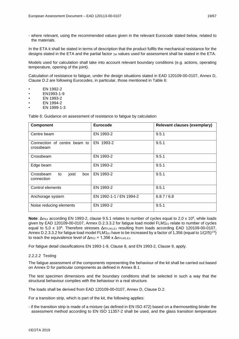
Calculation of resistance to fatigue, under the design situations stated in EAD 120109-00-0107, Annex D, Clause D.2 are following Eurocodes, in particular, those mentioned in Table 6:
• EN 1992-2 • EN1993-1-9 • EN 1993-2 • EN 1994-2 • EN 1999-1-3
Table 6: Guidance on assessment of resistance to fatigue by calculation
Component Eurocode Relevant clauses (exemplary)
Centre beam EN 1993-2 9.5.1
Connection of centre beam to crossbeam
EN 1993-2 9.5.1
Crossbeam EN 1993-2 9.5.1
Edge beam EN 1993-2 9.5.1
Crossbeam to joist box connection
EN 1993-2 9.5.1
Control elements EN 1993-2 9.5.1
Anchorage system EN 1992-1-1 / EN 1994-2 6.8.7 / 6.8
Noise reducing elements EN 1993-2 9.5.1
Note: ΔE2 according EN 1993-2, clause 9.5.1 relates to number of cycles equal to 2,0 x 10⁶, while loads given by EAD 120109-00-0107, Annex D.2.3.3.2 for fatigue load model FLM1EJ relate to number of cycles
equal to 5,0 x 10⁶. Therefore stresses ΔFLM1,EJ resulting from loads according EAD 120109-00-0107, Annex D.2.3.3.2 for fatigue load model FLM1EJ have to be increased by a factor of 1,356 (equal to 1/(2/5)1/3)
to reach the equivalence level of ΔE2 = 1,356 x ΔFLM1,EJ.
For fatigue detail classifications EN 1993-1-9, Clause 8, and EN 1993-2, Clause 9, apply.
2.2.2.2 Testing
The fatigue assessment of the components representing the behaviour of the kit shall be carried out based on Annex D for particular components as defined in Annex B.1.
The test specimen dimensions and the boundary conditions shall be selected in such a way that the structural behaviour complies with the behaviour in a real structure.
The loads shall be derived from EAD 120109-00-0107, Annex D, Clause D.2.
For a transition strip, which is part of the kit, the following applies:
- if the transition strip is made of a mixture (as defined in EN ISO 472) based on a thermosetting binder the assessment method according to EN ISO 11357-2 shall be used, and the glass transition temperature
European Assessment Document – EAD 120113-00-0107 20/67
©EOTA 2019
shall be stated in the ETA as this is related to the plastic deformation expected in case it does not exceed the maximum operating temperature;
- if it is made of thermoplastics binder (as defined in EN ISO 472) the assessment method according to EN 12697-22 shall be used, considering the maximum operating temperature;
- if the transition strip is made of a bituminous mixture, the assessment method according EN 12697-22 shall be used, considering the maximum operating temperature.
For the second and third type of transition strip the resulting maximum deformation shall be stated in the ETA.
2.2.3 Seismic behaviour
The assessment of seismic behaviour is referred to the categories given in EAD 120109-00-0107, Annex D, Clause D.2.4.2.3.
The movement capacity of a modular expansion joint including noise reducing elements does not allow movements in all directions, depending on the geometry of the noise reducing elements. The limitations of movements in all directions shall be assessed by analysis of the technical file and given in the ETA.
The seismic behaviour shall be assessed by analysis of the design of the expansion joint in relation to the categories given in EAD 120109-00-0107, Annex D, Clause D.2.4.2.3, using the principles for the total design value of the displacement (dealt with in EAD 120109-00-0107, Annex D, Clause D.2.4.2.3.2) in the seismic design situation according to EN 1998-2, Clause 2.3.6.3.
The assessed category and the relevant indications according to EAD 120109-00-0107, Annex D, Table D.8 shall be stated in the ETA.
2.2.4 Movement capacity
The movement capacity of an expansion joint is the possibility to allow the displacement of the parts of the main structure under unloaded and loaded conditions as given in EAD 120109-00-0107, Annex D, Clause D.2.
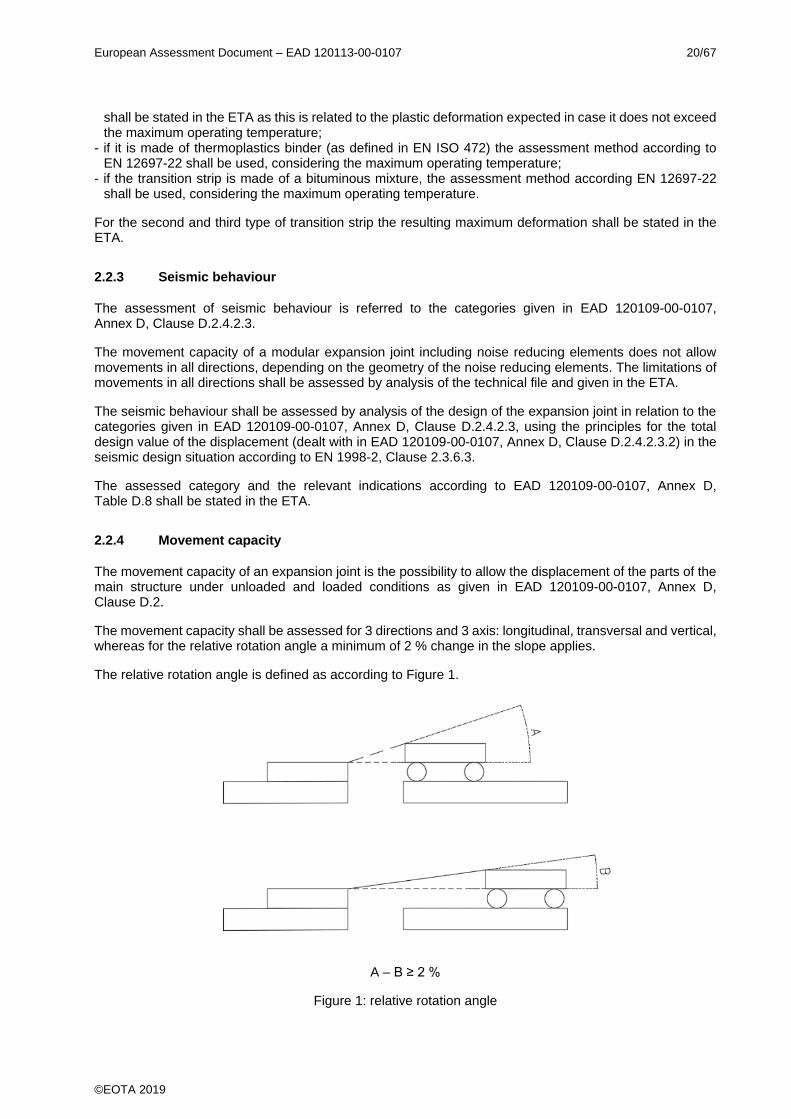
The movement capacity shall be assessed for 3 directions and 3 axis: longitudinal, transversal and vertical, whereas for the relative rotation angle a minimum of 2 % change in the slope applies.
The relative rotation angle is defined as according to Figure 1.
A – B ≥ 2 %
Figure 1: relative rotation angle

European Assessment Document – EAD 120113-00-0107 21/67
©EOTA 2019
The movement capacity, including the minimum opening in closed position, may either be defined by the manufacturer or is an outcome of the assessment.
The influence of displacement velocity and the temperature is not relevant for products according to this EAD.
If the seismic behaviour is included in the assessment, the accidental relative rotation angle (deviation of the slope in the traffic direction) shall be assessed for the accidental design situations according to EAD 120109-00-0107, Annex D, Clause D.2.4.2.2.
The movement capacity under unloaded conditions specified by the manufacturer shall be assessed.
The movement capacity shall be assessed by testing. The test method is described in EAD 120109-00-0107, Annex D, Clause D.3.
For a sealing element without mechanical fixing in edge profiles/centre beams (“compression seals”), the effect of creep and/or relaxation of the sealing element shall be considered by a pre-compression time of 24 h at the minimum opening before starting the test.
Where relevant, due attention shall be paid to the rotations.
In addition to the movement capacity, assessed by testing, the movement capacity shall also be assessed by means of analysis of kinematic behaviour for combinations of longitudinal movement, transverse movements perpendicular to the main direction of the superstructure, relative vertical movements between the main structures and rotations of and between components.
These values shall be assessed, including the influence of longitudinal slopes.
The results of the assessment of specified values according to the assessment method given above shall be stated in the ETA for the concerned directions. The results of the assessment for the movement capacity shall be stated in the ETA, including the reaction forces resulting from displacements and rotations.
The minimum clearances between the centre beams and between the edge beam and adjacent centre beam shall be stated in the ETA.
The maximum skew angle and related capacity for displacements and rotations shall be stated in the ETA.
2.2.5 Cleanability
The ability for self-cleanability shall be assessed by check of the design of the modular expansion joint or, if necessary, by an additional test in order to assess the contribution of the expansion joint opening and closing on it. This test is either carried out in parallel to the testing procedure for assessment of movement capacity according to EAD 120109-00-0107, Annex D, Clause D.3 or separately on a specimen including a single sealing element and its fixing, by depositing sand on the sealing element and assessing the removal of the sand under opening/closing movements of the joint. Separate testing according to EAD 120109-00-0107, Annex D, Clause D.3 of a single sealing element and its fixing is only possible for kits where all sealing elements and their fixations are identical.
For this purpose:
- During the 3rd and 4th cycles, addition of sand aggregate size of 2 mm (grading range 0 mm - 2 mm)
In addition, proper fixing and mechanical resistance of the sealing element and its clamping devices is assessed according to Annex F, whereas during and after the test the sealing element shall not be shifted in its clamping connections, detached, cracked or broken.
In case the modular expansion joint does include optional component(s), e.g. traffic noise reducing elements, which lead to situation that the assessment method introduced above cannot be applied, the following applies: Cleanability is assessed by means of accessibility (e.g. dismountable noise reducing elements) to the relevant part of the modular expansion joint (sealing element).

European Assessment Document – EAD 120113-00-0107 22/67
©EOTA 2019
The proper functioning of the expansion joint shall not be affected by accumulation of debris, whereas the following results of assessment apply: Self-cleaning; Cleanable; Not cleanable.
Self-cleaning means the joint can be closed to the minimum opening position at the end of the test.
Cleanable means the joint cannot be closed to the minimum opening position at the end of the test, but the sand can be removed manually.
Not cleanable means it is neither self-cleaning nor it can be cleaned manually for all opening positions.
2.2.6 Resistance to wear
The intended working life of the kit/component shall not be affected by wear which is caused by movements either between two parts of the joint or between parts of the joint and the main structure.
The accumulation of wear of the sliding surfaces shall not result in one or more of the conditions mentioned below:
- Insufficient mechanical resistance to meet the requirements of Clause 2.2.1 - Change in kinematic conditions (e.g. loss of original contact pressure in the sliding surface and with
respect to the planned load transfer in the joint in particular with respect to uplift forces) - Complete vanishing of the sliding material and/or the counter material - Increase of friction to a degree which causes damage to the expansion joint with respect to imposed
movements
This means that, in relation to temperature effects in the bridge, the total slide path for the test procedure given below, in relation to a working life of “a” years of a component is derived from [a] x 365 x 0,33 x maximum movement capacity of the expansion joint = 120 x [a] cycles with maximum movement capacity of the joint (a = number of years).
The testing procedure is given in Annex D.
The intended working life with respect to wear of a component shall be assessed based on the concept that on average each day results in a movement of the expansion joint equal to 33 % of the maximum movement capacity.
The assessed component replaceability category according to Table 2 for components subject to wear and related intended working life shall be given in the ETA.
2.2.7 Watertightness
It shall be assessed whether the main structure and, where relevant, the sub-components of the modular expansion joint under the running surface are protected from water and its chemical contents.
For the assessment of the watertightness of the modular expansion joint, the test method is described in EAD 120109-00-0107, Annex D, Clause D.4.
For the test method according to EAD 120109-00-0107, Annex D, Clause D.4, the worst condition is defined by the maximum offset between two adjacent centre beams and imposed deformations at bends (i.e. at kerb units), whereas opening position with most adverse effects (longitudinal, transverse) on the sealing elements fixings applies.
In addition, for the sealing element and its clamping device its proper fixing and mechanical resistance shall be assessed according to Annex F, whereas during and after the test the sealing element shall not be shifted in its clamping connections, detached, cracked or broken.
Watertightness is given if the assessments according to EAD 120109-00-0107, Annex D and Annex F of this EAD are passed.

European Assessment Document – EAD 120113-00-0107 23/67
©EOTA 2019
For a sealing element without mechanical fixing in edge profiles (“compression seals”) the effect of creep and/or relaxation of the sealing element shall be considered by a pre-compression time of 24 h at the minimum opening before starting the test.
The result of the assessment of the watertightness (moisture under the joint) shall be stated in the ETA, whereas the following results of assessment apply: Watertight; Not watertight.
In addition:
Where a watertight connection between the waterproofing system of the main structure and the expansion joint is foreseen as component of the expansion joint, for the assessment according to EAD 120109-00-0107, Annex D, the last paragraph in Clause D.4.4.1 applies in addition.
The type of the connection shall be described in the ETA.
The result of the assessment of the watertightness (moisture under the joint) shall be stated in the ETA, whereas the following results of assessment apply: Watertight; Not watertight.
2.2.8 Durability
2.2.8.1 Corrosion
For metallic surfaces of components, the climatic classification in accordance with EN ISO 9223 (see Clause 1.1) with respect to the intended use of the product is taken into account.
It shall be assessed whether the corrosion protection layout for the concerned kit conforms to the conditions given in the scope of the EAD (possibly using the technical documentation of the manufacturer).
Galvanic corrosion is not assessed.
Based on the manufacturer’s technical documentation for the corrosion protection system the durability class in relation to the corrosivity class according to the standards given in Clause 1.1 shall be given in the ETA.
2.2.8.2 Chemicals
Assessment of the resistance to de-icing salts of the sealing element shall be done according to ISO 1817 (immersion for 14 days 23 °C, 4 % sodium- chloride solution or equivalent).
The sealing element shall show no decrease of hardness exceeding 5 Points and no increase of volume exceeding 10 %.
2.2.8.3 Loss of performance due to ageing resulting from temperature and ozone
The performance of the modular expansion joint shall not be affected by ageing. For the product according to this EAD this applies to components made of elastomer and plastics.
This clause, including its sub clauses, does not apply for components made of PTFE according to Annex B, Table B.2.3.
2.2.8.3.1 Resistance to ageing resulting from temperature
To assess the sensitivity of the components made of elastomer (defined in Annex B) to elevated temperature, the material shall be subjected to test method ISO 188 (Method A). The minimal conditions of exposure are the following: 14 days at a temperature of 70 °C.
The hardness before and after ageing is measured according to ISO 48-2 or ISO 48-4 respectively, the tensile strength and the elongation at break are measured according to ISO 37.
To assess the sensitivity of the components made of plastics (defined in Annex B) to elevated temperature, the material shall be subjected to test method EN ISO 2578 and EN ISO 11403-3, Clause 6.5 respectively at +50°C.

European Assessment Document – EAD 120113-00-0107 24/67
©EOTA 2019
The hardness before and after ageing is measured according to EN ISO 2039-1, the tensile strength and the elongation at break are measured according to EN ISO 527-2.
After ageing of the elastomer, the change in hardness and the change of tensile properties of the aged specimen shall be within:
Hardness ≤ + 7 points
Tensile strength ≥ -20%
Elongation at break ≥ -30%
For plastics, assessment shall be done in equivalence to the values for elastomers.
These values apply for all working life categories.
For the assessment of the resistance of the components made of elastomer to low temperatures, the brittleness test according to ISO 812, Method B, applies.
With respect to the operating temperature according to Clause 1.2.1, for the execution of the brittleness test for components made of elastomer the following temperatures apply:
-25 °C for operating temperatures down to -20 °C,
-40 °C for operating temperature equal to -30 °C,
-55 °C for operating temperature equal to -40 °C.
For bearings, prestress elements and control elements made of elastomer the brittleness test is carried out according to ISO 812, Method B at -35 °C.
With respect to the operating temperature according to Clause 1.2.1, for the execution of the brittleness test of components made of plastics (according to Annex B, Table B.2.4) the following temperatures apply:
-25 °C for operating temperature down to -20 °C,
-40 °C for operating temperature equal to -30 °C and -40 °C.
For bearings, prestress elements and control elements, if relevant according to their design, adhesion is assessed according to ISO 813 (peel at 90 °C).
Regarding components made of thermoplastic elastomer the following applies: In order to assess the sensitivity of the components made of thermoplastic elastomer (defined in Annex B) to elevated temperature, the material shall be subjected to test method ISO 188 (Method A). The minimal conditions of exposure are the following: 14 days at a temperature of 70°C. The hardness before and after ageing is measured according to ISO 48-4, the tensile strength and the elongation at break are measured according to ISO 37.
For thermoplastic elastomers, the assessment shall be done in equivalence to the values for elastomers.
For control elements made of thermoplastic elastomer for the assessment of the resistance to low temperatures, the brittleness test is carried out according to EN ISO 6721-2 and EN ISO 11357-2 at -35°C.
2.2.8.3.2 Resistance to ageing resulting from ozone
To assess the sensitivity to ozone of the components made of elastomer (defined in Annex B), the material shall undergo a test. The test specimen shall be assessed according to test method ISO 1431-1 (Test procedure A: static condition).
The test conditions for elastomers are the following: 72 hours of exposure at the temperature of 40 °C, with an ozone concentration of 50 pphm. The test specimen is submitted to 20 % of elongation.
The sensitivity to ozone of the components made of thermoplastic elastomer shall be assessed. The test specimen shall be assessed according to test method ISO 1431-1 (Test procedure A: static condition). The

European Assessment Document – EAD 120113-00-0107 25/67
©EOTA 2019
test conditions for thermoplastic elastomer comply with those for elastomer, except for elongation: the value given in the manufacturers technical file applies.
After the test no cracks shall occur.
2.2.8.3.3 Resistance against freeze – thaw
If relevant, the degradation of porous materials (e.g. mortar), to freeze-thaw shall be assessed by testing. Test specimen(s) of the material or component shall be subjected to freeze/thaw cycles in accordance with EN 13687-1. According to the use of the product, the number of cycles shall be 50 (see EN 1504-2, Tables 5, line 9 and Table 1, 1.3 and 5.1).
After the test, no degradation shall be observed.
2.2.9 Content, emission and/or release of dangerous substances
The performance of the product related to the emissions and/or release and, where appropriate, the content
of dangerous substances will be assessed on the basis of the information provided by the manufacturer2 after identifying the release scenarios (in accordance with EOTA TR 034) taking into account the intended use of the product and the Member States where the manufacturer intends his product to be made available on the market.
The identified intended release scenario for this product and intended use with respect to dangerous substances is:
S/W2: Product with indirect contact to soil, ground- and surface water
2.2.9.1 Leachable substances
For the intended use covered by the release scenario S/W2 the performance of the sealing element
concerning leachable substances has to be assessed. A leaching test with subsequent eluate analysis
must take place, each in duplicate. For the leaching tests of the sealing element EAD 120109-00-0107,
Annex D, Clause D.6 applies.
2.2.10 Ability to bridge gaps and levels in the running surface
2.2.10.1 Allowable surface gaps and voids
The maximum dimensions of the gaps and voids of the joint at the surface level depend on the three user categories.
For the range of the skew angle β (see Figure 2) to be assessed for all user categories the following requirements shall be met.
For vehicles and cyclists categories the expansion joint shall not allow a vertical displacement of more than the radius of a 10,0 cm diameter sphere placed anywhere on the running surface level.
2 The manufacturer may be asked to provide to the TAB the REACH related information which he must accompany the DoP with (cf. Article 6(5) of Regulation (EU) No 305/2011).
The manufacturer is not obliged:
− to provide the chemical constitution and composition of the product (or of constituents of the product) to the TAB, or
− to provide a written declaration to the TAB stating whether the product (or constituents of the product) contain(s) substances which are classified as dangerous according to Directive 67/548/EEC and Regulation (EC) No 1272/2008 and listed in the "Indicative list on dangerous substances" of the SGDS.
Any information provided by the manufacturer regarding the chemical composition of the products may not be distributed to EOTA or to TABs.
European Assessment Document – EAD 120113-00-0107 26/67
©EOTA 2019
a) Vehicles
The expansion joint shall not allow a vertical displacement of 1,0 cm or more of the following bodies, in conjunction with the traffic direction:
- a horizontal prism with plan dimensions 10,0 cm by 20,0 cm placed horizontally anywhere and in any direction,
- a horizontal prism with plan dimensions 6,5 cm by 22,0 cm placed horizontally anywhere with a deviation from the traffic direction α of -20° to +20°,
- a horizontal prism with plan dimensions 4,5 cm by 35,0 cm placed horizontally anywhere with a deviation from the traffic direction α of -20° to +20°.
b) Cyclists
The expansion joint shall not allow a vertical displacement of 1,0 cm or more of the following bodies, in conjunction with the traffic direction:
- a horizontal prism with plan dimensions 2,0 cm by 22,0 cm placed horizontally everywhere with a deviation from the traffic direction α of -20° to +20°,
- a horizontal prism with plan dimensions 10,0 cm by 20,0 cm placed horizontally everywhere and in any direction.
The design of the expansion joint for the carriageway can be adapted by special measures to fulfil the above requirement (see Clause 1.1).
c) Pedestrians
The expansion joint shall not allow a vertical displacement of 2,0 cm or more of a disk with a diameter of 8,0 cm placed horizontally everywhere.
Assessment shall be carried out by analysis of the technical file and, when needed, by use of measurements tools given above.
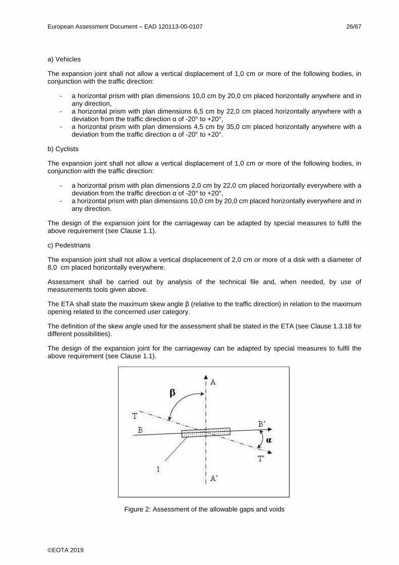
The ETA shall state the maximum skew angle β (relative to the traffic direction) in relation to the maximum opening related to the concerned user category.
The definition of the skew angle used for the assessment shall be stated in the ETA (see Clause 1.3.18 for different possibilities).
The design of the expansion joint for the carriageway can be adapted by special measures to fulfil the above requirement (see Clause 1.1).
Figure 2: Assessment of the allowable gaps and voids
European Assessment Document – EAD 120113-00-0107 27/67
©EOTA 2019
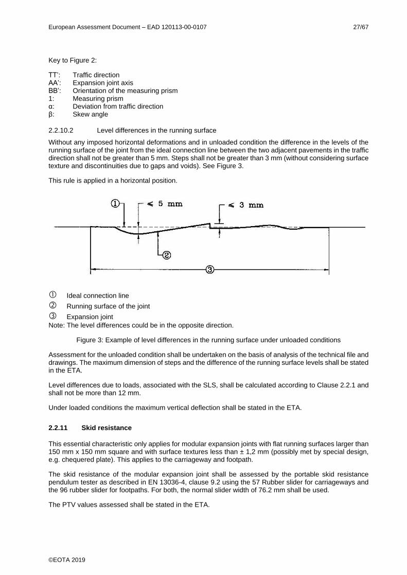
Key to Figure 2:
TT’: Traffic direction AA’: Expansion joint axis BB’: Orientation of the measuring prism 1: Measuring prism α: Deviation from traffic direction β: Skew angle
2.2.10.2 Level differences in the running surface
Without any imposed horizontal deformations and in unloaded condition the difference in the levels of the running surface of the joint from the ideal connection line between the two adjacent pavements in the traffic direction shall not be greater than 5 mm. Steps shall not be greater than 3 mm (without considering surface texture and discontinuities due to gaps and voids). See Figure 3.
This rule is applied in a horizontal position.
Ideal connection line
Running surface of the joint
Expansion joint
Note: The level differences could be in the opposite direction.
Figure 3: Example of level differences in the running surface under unloaded conditions
Assessment for the unloaded condition shall be undertaken on the basis of analysis of the technical file and drawings. The maximum dimension of steps and the difference of the running surface levels shall be stated in the ETA.
Level differences due to loads, associated with the SLS, shall be calculated according to Clause 2.2.1 and shall not be more than 12 mm.
Under loaded conditions the maximum vertical deflection shall be stated in the ETA.
2.2.11 Skid resistance
This essential characteristic only applies for modular expansion joints with flat running surfaces larger than 150 mm x 150 mm square and with surface textures less than ± 1,2 mm (possibly met by special design, e.g. chequered plate). This applies to the carriageway and footpath.
The skid resistance of the modular expansion joint shall be assessed by the portable skid resistance pendulum tester as described in EN 13036-4, clause 9.2 using the 57 Rubber slider for carriageways and the 96 rubber slider for footpaths. For both, the normal slider width of 76.2 mm shall be used.
The PTV values assessed shall be stated in the ETA.

European Assessment Document – EAD 120113-00-0107 28/67
©EOTA 2019
2.2.12 Drainage capacity
Where relevant due to the modular expansion joint kit is including a drainage device (according to EAD 120109-00-0107, Annex D, Figure D.11) the drainage capacity shall be assessed according to the assessment method described EAD 120109-00-0107, Annex D, Clause D.5. The drainage capacity in mm³/sec together with definition of the porous pavement as defined according to the assessment method in EAD 120109-00-0107, Annex D, Clause D.5, shall be stated in the ETA.
3 ASSESSMENT AND VERIFICATION OF CONSTANCY OF PERFORMANCE
3.1 System(s) of assessment and verification of constancy of performance to be applied
For the products covered by this EAD the applicable European legal act is: Decision 2001/19/EC
The system is: 1
The performance of any kit component which is obtained from a component manufacturer and is CE marked on the basis of a hEN or an EAD will, (for the purposes of verification of constancy of performance) be considered to be the performance declared by the component manufacturer in his DoP. The component does not need to be re-assessed regarding this performance aspect.
3.2 Tasks of the manufacturer
The cornerstones of the actions to be undertaken by the manufacturer of the product in the procedure of assessment and verification of constancy of performance are laid down in Table 7.
In case of components manufactured by separate manufacturers, the FPC as indicated in the Table below is related to relevant documentation provided by the manufacturer of the expansion joint.
European Assessment Document – EAD 120113-00-0107 29/67
©EOTA 2019
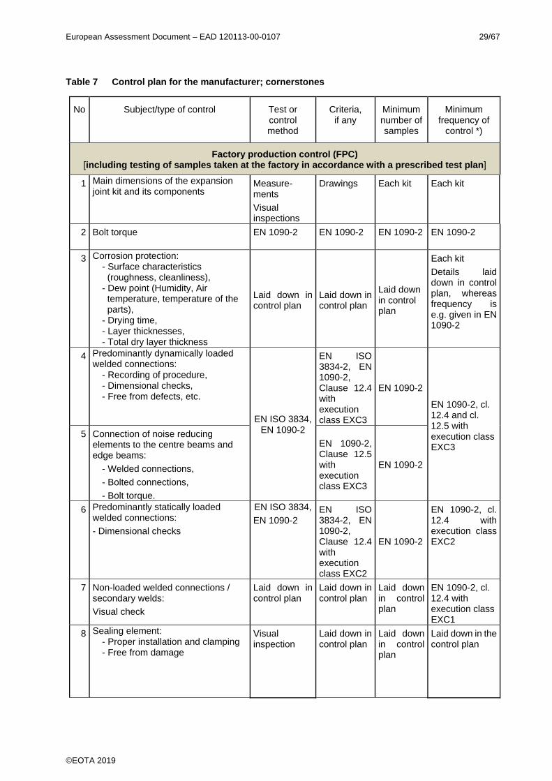
Table 7 Control plan for the manufacturer; cornerstones
No Subject/type of control Test or control method
Criteria, if any
Minimum number of samples
Minimum frequency of
control *)
Factory production control (FPC) [including testing of samples taken at the factory in accordance with a prescribed test plan]
1 Main dimensions of the expansion joint kit and its components
Measure-ments
Visual inspections
Drawings Each kit Each kit
2 Bolt torque EN 1090-2 EN 1090-2 EN 1090-2 EN 1090-2
3 Corrosion protection: - Surface characteristics
(roughness, cleanliness), - Dew point (Humidity, Air
temperature, temperature of the parts),
- Drying time, - Layer thicknesses, - Total dry layer thickness
Laid down in control plan
Laid down in control plan
Laid down in control plan
Each kit
Details laid down in control plan, whereas frequency is e.g. given in EN 1090-2
4 Predominantly dynamically loaded welded connections:
- Recording of procedure, - Dimensional checks, - Free from defects, etc.
EN ISO 3834, EN 1090-2
EN ISO 3834-2, EN 1090-2, Clause 12.4 with execution class EXC3
EN 1090-2
EN 1090-2, cl. 12.4 and cl. 12.5 with execution class EXC3
5 Connection of noise reducing elements to the centre beams and edge beams:
- Welded connections,
- Bolted connections,
- Bolt torque.
EN 1090-2, Clause 12.5 with execution class EXC3
EN 1090-2
6 Predominantly statically loaded welded connections:
- Dimensional checks
EN ISO 3834,
EN 1090-2 EN ISO 3834-2, EN 1090-2, Clause 12.4 with execution class EXC2
EN 1090-2
EN 1090-2, cl. 12.4 with execution class EXC2
7 Non-loaded welded connections / secondary welds:
Visual check
Laid down in control plan
Laid down in control plan
Laid down in control plan
EN 1090-2, cl. 12.4 with execution class EXC1
8 Sealing element: - Proper installation and clamping - Free from damage
Visual inspection
Laid down in control plan
Laid down in control plan
Laid down in the control plan
European Assessment Document – EAD 120113-00-0107 30/67
©EOTA 2019
No Subject/type of control Test or control method
Criteria, if any
Minimum number of samples
Minimum frequency of
control *)
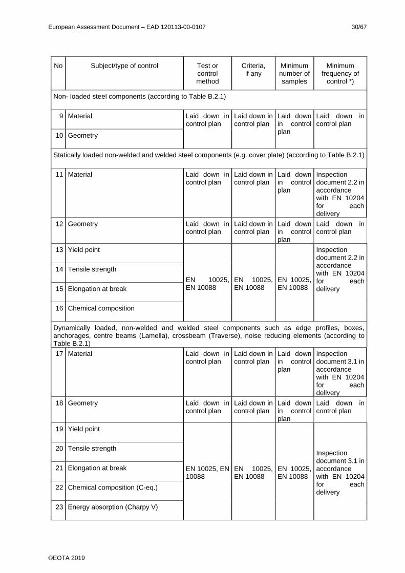
Non- loaded steel components (according to Table B.2.1)
9 Material Laid down in control plan
Laid down in control plan
Laid down in control plan
Laid down in control plan
10 Geometry
Statically loaded non-welded and welded steel components (e.g. cover plate) (according to Table B.2.1)
11 Material Laid down in control plan
Laid down in control plan
Laid down in control plan
Inspection document 2.2 in accordance with EN 10204 for each delivery
12 Geometry Laid down in control plan
Laid down in control plan
Laid down in control plan
Laid down in control plan
13 Yield point
EN 10025, EN 10088
EN 10025, EN 10088
EN 10025, EN 10088
Inspection document 2.2 in accordance with EN 10204 for each delivery
14 Tensile strength
15 Elongation at break
16 Chemical composition
Dynamically loaded, non-welded and welded steel components such as edge profiles, boxes, anchorages, centre beams (Lamella), crossbeam (Traverse), noise reducing elements (according to Table B.2.1)
17 Material Laid down in control plan
Laid down in control plan
Laid down in control plan
Inspection document 3.1 in accordance with EN 10204 for each delivery
18 Geometry Laid down in control plan
Laid down in control plan
Laid down in control plan
Laid down in control plan
19 Yield point
EN 10025, EN 10088
EN 10025, EN 10088
EN 10025, EN 10088
Inspection document 3.1 in accordance with EN 10204 for each delivery
20 Tensile strength
21 Elongation at break
22 Chemical composition (C-eq.)
23 Energy absorption (Charpy V)
European Assessment Document – EAD 120113-00-0107 31/67
©EOTA 2019
No Subject/type of control Test or control method
Criteria, if any
Minimum number of samples
Minimum frequency of
control *)
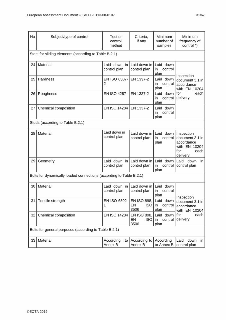
Steel for sliding elements (according to Table B.2.1)
24 Material Laid down in control plan
Laid down in control plan
Laid down in control plan
Inspection document 3.1 in accordance with EN 10204 for each delivery
25 Hardness EN ISO 6507-2
EN 1337-2 Laid down in control plan
26 Roughness EN ISO 4287 EN 1337-2 Laid down in control plan
27 Chemical composition EN ISO 14284 EN 1337-2 Laid down in control plan
Studs (according to Table B.2.1)
28 Material Laid down in control plan
Laid down in control plan
Laid down in control plan
Inspection document 3.1 in accordance with EN 10204 for each delivery
29 Geometry Laid down in control plan
Laid down in control plan
Laid down in control plan
Laid down in control plan
Bolts for dynamically loaded connections (according to Table B.2.1)
30 Material Laid down in control plan
Laid down in control plan
Laid down in control plan
Inspection document 3.1 in accordance with EN 10204 for each delivery
31 Tensile strength EN ISO 6892-1
EN ISO 898, EN ISO 3506
Laid down in control plan
32 Chemical composition EN ISO 14284 EN ISO 898, EN ISO 3506
Laid down in control plan
Bolts for general purposes (according to Table B.2.1)
33 Material According to Annex B
According to Annex B
According to Annex B
Laid down in control plan

European Assessment Document – EAD 120113-00-0107 32/67
©EOTA 2019
No Subject/type of control Test or control method
Criteria, if any
Minimum number of samples
Minimum frequency of
control *)
Sealing element made of elastomer (according to Table B.2.2)
34 Density ISO 2781
Laid down in the control
plan
According to the relevant standard.
Each batch, or Inspection document 3.1 according to EN 10204 at each delivery. 35 Hardness IRHD/Shore hardness ISO 48-2/ ISO
48-4
36 Tensile strength ISO 37
37 Elongation at break ISO 37
38 Tear resistance ISO 34-1 Once per year
39 Compression set ISO 815-1
24 h and 70 °C constant deflexion 25 %
Once per year
40 Thermogravimetric analysis (TGA) ISO 9924-1 or ISO 9924-3
Once per year
Components made of elastomer (e.g. in bearings, prestress and control elements) (according to Table B.2.3)
41 Material/ Compound number Laid down in the control plan
Laid down in the control
plan
Laid down in the control plan
Inspection document 3.1 according to EN 10204 at each delivery.
42 Density ISO 2781 Each batch
43 Hardness IRHD/Shore hardness ISO 48-2 or ISO 48-4
Each batch
44 Tensile strength and Elongation at break (if subject to tensile stress)
ISO 37 Each batch
45 Tear resistance ISO 34-1 Method A
Once per year
46 Shear stiffness (if subject to tensile stress)
ISO 1827 Once per year
47 Compression set (if subject to shear) ISO 815-1 24 h and 70 °C constant deflexion 25 %
Once per year
European Assessment Document – EAD 120113-00-0107 33/67
©EOTA 2019
No Subject/type of control Test or control method
Criteria, if any
Minimum number of samples
Minimum frequency of
control *)
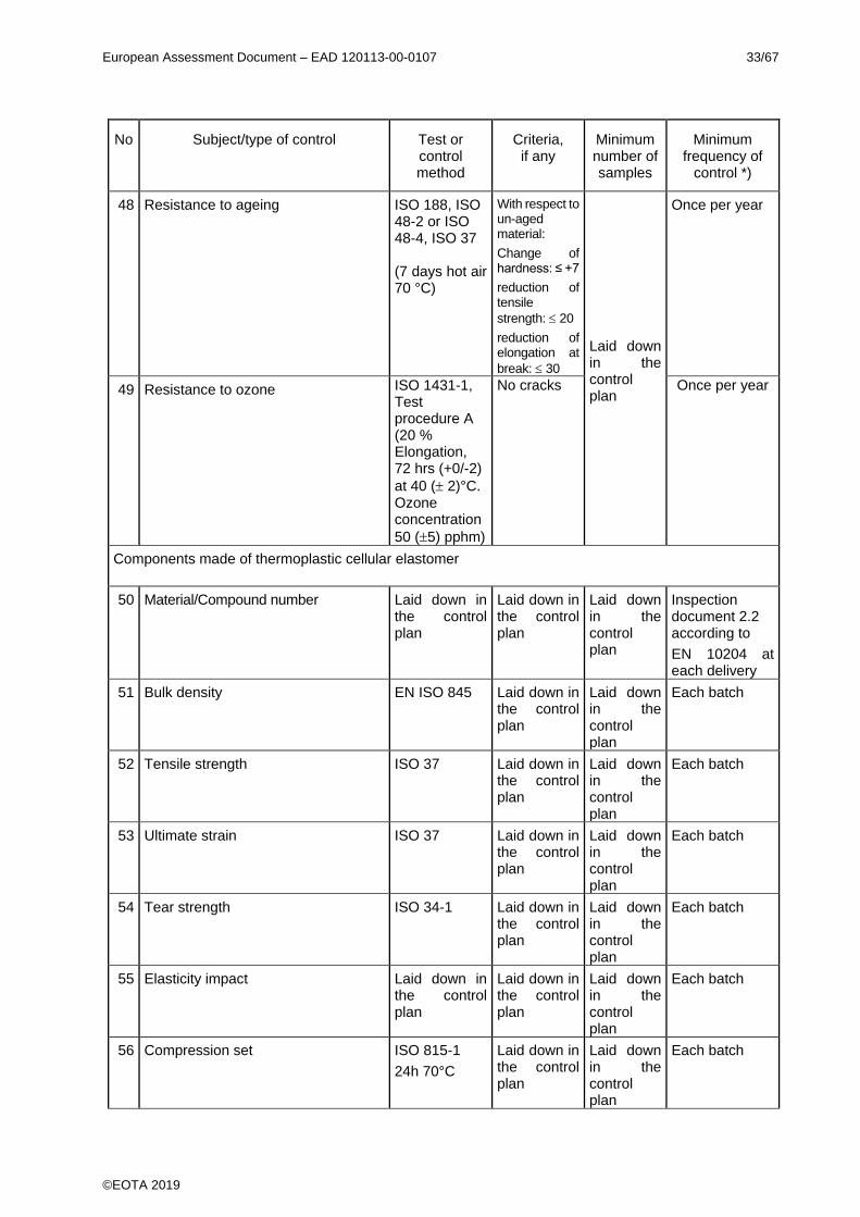
48 Resistance to ageing ISO 188, ISO 48-2 or ISO 48-4, ISO 37 (7 days hot air 70 °C)
With respect to un-aged material:
Change of hardness: ≤ +7
reduction of tensile
strength: 20
reduction of elongation at
break: 30
Laid down in the control plan
Once per year
49 Resistance to ozone ISO 1431-1, Test procedure A (20 % Elongation, 72 hrs (+0/-2)
at 40 ( 2)°C. Ozone concentration
50 (5) pphm)
No cracks Once per year
Components made of thermoplastic cellular elastomer
50 Material/Compound number Laid down in the control plan
Laid down in the control plan
Laid down in the control plan
Inspection document 2.2 according to
EN 10204 at each delivery
51 Bulk density EN ISO 845 Laid down in the control plan
Laid down in the control plan
Each batch
52 Tensile strength ISO 37 Laid down in the control plan
Laid down in the control plan
Each batch
53 Ultimate strain ISO 37 Laid down in the control plan
Laid down in the control plan
Each batch
54 Tear strength ISO 34-1 Laid down in the control plan
Laid down in the control plan
Each batch
55 Elasticity impact Laid down in the control plan
Laid down in the control plan
Laid down in the control plan
Each batch
56 Compression set ISO 815-1
24h 70°C
Laid down in the control plan
Laid down in the control plan
Each batch

European Assessment Document – EAD 120113-00-0107 34/67
©EOTA 2019
No Subject/type of control Test or control method
Criteria, if any
Minimum number of samples
Minimum frequency of
control *)
57 Torsion test EN ISO 6721-2
Laid down in the control plan
Laid down in the control plan
Each batch
58 Ageing EN ISO 3386
5d, 80°C, 95% r.h.
Laid down in the control plan
Laid down in the control plan
Each batch
PTFE for sliding bearings, prestress elements and guides
59 Material/Compound number Laid down in control plan
Laid down in control plan
Laid down in control plan
Certificate at each delivery
60 Density ISO 1183 Laid down in control plan in accordance with Table B.2.3
Each batch
61 Hardness (Ball indentation hardness) ISO 2039-1 Each batch
62 Tensile characteristics [N/mm²] and Elongation at break [%]
EN ISO 527-1 Each batch
Components made of polyamide (PA), polyoxymethylene (POM) and polyethylene (PE) (including UHMWPE)
63 Material/Compound number Laid down in control plan
Laid down in control plan
Laid down in control plan
Inspection document 2.2 according to EN 10204 at each delivery.
64 Density ISO 1183 Max. 5 % deviation from initial value
Each batch
65 Hardness Shore D EN ISO 868 Laid down in control plan
Each batch
66 Tensile characteristics (if subject to tension)
EN ISO 527-1 Laid down in control plan
Each batch
67 Shear strength (if subject to shear) ISO 1827 Laid down in control plan
Each batch
68 E modulus in tension (if subject to tension)
EN ISO 527-1 Laid down in control plan
If relevant
69 Compressive strength (if subject to pressure)
EN ISO 604 Laid down in control plan
If relevant
70 E modulus in compression (if subject to pressure)
EN ISO 604 Laid down in control plan
If relevant
71 Elongation at break EN ISO 527-1 Laid down in control plan
Each batch
72 Energy absorption (Charpy test)
EN ISO 179 Laid down in control plan
Each batch

European Assessment Document – EAD 120113-00-0107 35/67
©EOTA 2019
No Subject/type of control Test or control method
Criteria, if any
Minimum number of samples
Minimum frequency of
control *)
Sealing element clamping device
73 Material Laid down in control plan
Laid down in control plan
Laid down in control plan
Each batch or delivery
74 Geometry
Ready mixed concrete for transition strip if part of the product
75 According to the relevant technical specification.
E.g. EN 206
Laid down in control plan.
Laid down in control plan.
Laid down in control plan.
Identification according to the standard at each delivery.
Transition strip made of thermosetting or thermoplastics binder (according to EN ISO 472) or bituminous mixture
Details to be laid down in the control plan Laid down in control plan.
Laid down in control plan.
Laid down in control plan.
Identification according to the standard at each delivery.
Resin mortar for transition strip and cement mortar for transition strip if part of the product
According to the agreement between TAB and manufacturer specification, define e.g.:
Frequencies shall be defined according to the agreement between TAB and the manufacturer in function of the quantity used and in order to guarantee a correct level of quality.
76 Resin
- Elongation at break
- Compressive strength
- Modulus of elasticity
Laid down in control plan.
Laid down in control plan.
Laid down in control plan.
77 Aggregate and fillers:
- Type
- Grading
- Resistance to fragmentation
- Polished Stone Value (PSV)
EN 932-3
Laid down in control plan.
Laid down in control plan.
EN 933-1 Laid down in control plan.
Laid down in control plan.
EN 1097-2 Laid down in control plan.
Laid down in control plan.
EN 1097-8 Laid down in control plan.
Laid down in control plan.
78 Mortar:
Compressive strength
Laid down in control plan.
Laid down in control plan.
Laid down in control plan.
Components made of stainless steel or aluminium for drainage device, if part of the kit (see EAD 120109-00-0107, Annex D, Figure D.11)
79 Parameters laid down in the control plan
Laid down in the control
plan
Laid down in the control
plan
Laid down in the control plan
Laid down in the control plan
(1): Arrangement means how the crossbeams are positioned in the structure, with their details. *) In case of irregular production it is possible to agree different frequency between manufacturer and notified body.

European Assessment Document – EAD 120113-00-0107 36/67
©EOTA 2019
3.3 Tasks of the notified body
The cornerstones of the actions to be undertaken by the notified body in the procedure of assessment and verification of constancy of performance for modular expansion joints are laid down in Table 8.
The performance of the components covered by hENs regarding those characteristics declared already by the component manufacturers in their DoP should not be assessed when the product (the kit) will be assessed by the TAB. The performance of those components for the purpose of issuing the ETA will be considered to be the performance declared by the manufacturers of the component. TABs may only assess the performance of the components only for essential characteristics not declared by the manufacturer of the component in his DoP.
Table 8 Control plan for the notified body; cornerstones
No Subject/type of control (product, raw/constituent material,
component - indicating characteristic concerned)
Test or control method
Criteria, if any
Minimum number of samples
Minimum frequency of
control
Initial inspection of the manufacturing plant and of factory production control
1 Ascertain that the factory production control with the staff and equipment are suitable to ensure a continuous and orderly manufacturing of the expansion joint.
As defined in the control plan.
As defined in the control plan.
As defined in the control plan.
1
Continuous surveillance, assessment and evaluation of factory production control
2 Continuous surveillance, assessment and evaluation of factory production control carried out by the manufacturer (parameters according to Table 7 of this EAD).
As defined in the control plan.
As defined in the control plan.
As defined in the control plan.
At least once a year

European Assessment Document – EAD 120113-00-0107 37/67
©EOTA 2019
4 REFERENCE DOCUMENTS
The following documents, in whole or in part, are normatively referenced in this European Assessment Document and are indispensable for its application. Only the specified edition applies.
EN 206:2013+A1:2016 Concrete - Specification, performance, production and conformity
EN 932-3:1996 + A1:2003
Tests for general properties of aggregates - Part 3: Procedure and terminology for simplified petrographic description
EN 933-1:2012 Tests for geometrical properties of aggregates - Part 1: Determination of particle size distribution - Sieving method
EN 1090-2:2018 Eurocode: Execution of steel structures and aluminium structures - Part 2: Technical requirements for steel structures
EN 1097-2:2010 Tests for mechanical and physical properties of aggregates - Part 2: Methods for the determination of resistance to fragmentation
EN 1097-8:2009 Tests for mechanical and physical properties of aggregates - Part 8: Determination of the polished stone value
EN 1337-2:2004 Structural bearing : Part 2: Sliding elements
EN 1504-2:2004 Products and systems for the protection and repair of concrete structures - Definitions, requirements, quality control and evaluation of conformity - Part 2: Surface protection systems for concrete
EN 1990:2002 + A1:2005 + A1:2005/AC:2010
Eurocode: Basis of structural design
EN 1991-1-5:2003 + AC:2009
Eurocode 1: Actions on structures - Part 1-5: General actions - Thermal actions
EN 1991-2:2003 + AC:2010
Eurocode 1: Actions on structures - Part 2: Traffic loads on bridges
EN 1992-1-1:2004 + AC:2010
Eurocode 2: Design of concrete structures - Part 1-1: General rules and rules for buildings
EN 1992-2:2005 + AC:2008
Eurocode 2: Design of concrete structures - Part 2: Concrete bridges - Design and detailing rules
EN 1993-1-1:2005 + AC:2009
Eurocode 3: Design of steel structures - Part 1-1: General rules and rules for buildings
EN 1993-1-4:2006 + A1:2015
Eurocode 3: Design of steel structures - Part 1-4: General rules - Supplementary rules for stainless steels
EN 1993-1-8:2005 + AC:2009
Eurocode 3: Design of steel structure - Part 1-8: Design of joints
EN 1993-1-9:2005 + AC:2009
Eurocode 3: Design of steel structures - Part 1-9: Fatigue
EN 1993-1-10:2005 + AC:2009
Eurocode 3: Design of steel structures - Part 1-10: Material toughness and through-thickness properties
EN 1993-2:2006 + AC:2009
Eurocode 3: Design of steel structures - Part 2: Steel Bridges
EN 1994-2:2005 + AC:2008
Eurocode 4: Design of composite steel and concrete structures - Part 2: General rules and rules for bridges
EN 1998-2:2005 + A1:2009 + A2:2011 + AC:2010
Eurocode 8: Design of structures for earthquake resistance - Part 2: Bridges
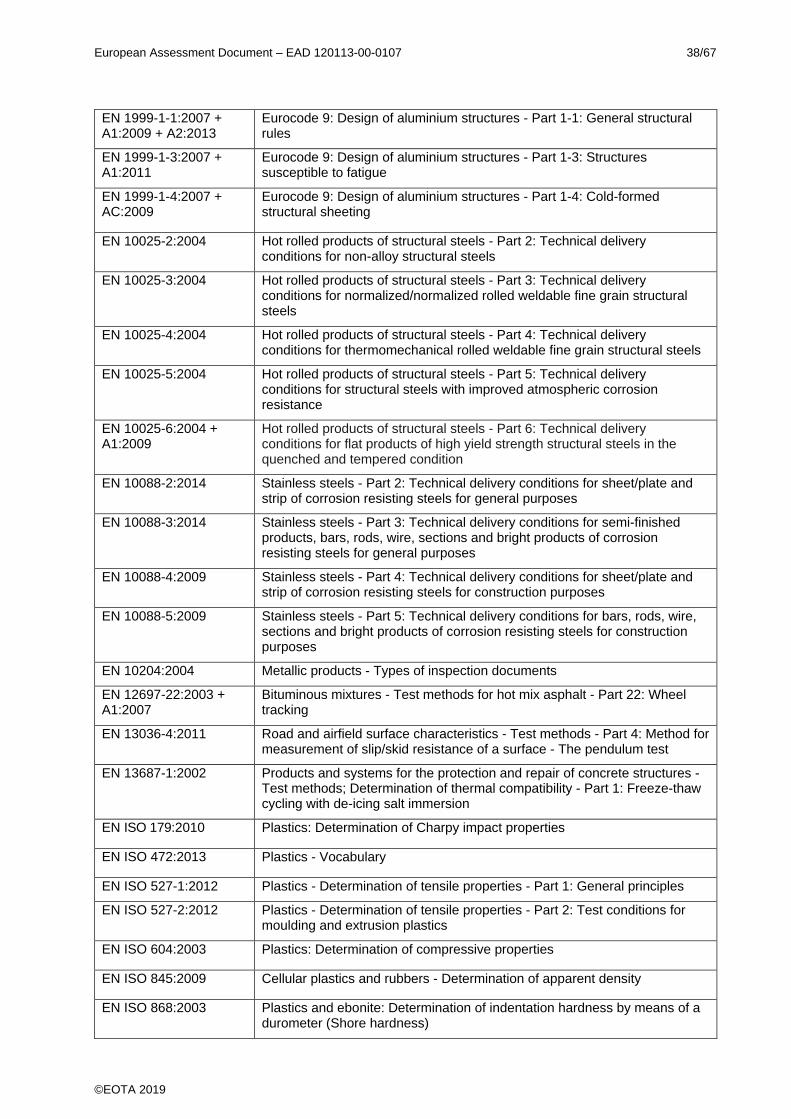
European Assessment Document – EAD 120113-00-0107 38/67
©EOTA 2019
EN 1999-1-1:2007 + A1:2009 + A2:2013
Eurocode 9: Design of aluminium structures - Part 1-1: General structural rules
EN 1999-1-3:2007 + A1:2011
Eurocode 9: Design of aluminium structures - Part 1-3: Structures susceptible to fatigue
EN 1999-1-4:2007 + AC:2009
Eurocode 9: Design of aluminium structures - Part 1-4: Cold-formed structural sheeting
EN 10025-2:2004 Hot rolled products of structural steels - Part 2: Technical delivery conditions for non-alloy structural steels
EN 10025-3:2004 Hot rolled products of structural steels - Part 3: Technical delivery conditions for normalized/normalized rolled weldable fine grain structural steels
EN 10025-4:2004 Hot rolled products of structural steels - Part 4: Technical delivery conditions for thermomechanical rolled weldable fine grain structural steels
EN 10025-5:2004 Hot rolled products of structural steels - Part 5: Technical delivery conditions for structural steels with improved atmospheric corrosion resistance
EN 10025-6:2004 + A1:2009
Hot rolled products of structural steels - Part 6: Technical delivery conditions for flat products of high yield strength structural steels in the quenched and tempered condition
EN 10088-2:2014 Stainless steels - Part 2: Technical delivery conditions for sheet/plate and strip of corrosion resisting steels for general purposes
EN 10088-3:2014 Stainless steels - Part 3: Technical delivery conditions for semi-finished products, bars, rods, wire, sections and bright products of corrosion resisting steels for general purposes
EN 10088-4:2009 Stainless steels - Part 4: Technical delivery conditions for sheet/plate and strip of corrosion resisting steels for construction purposes
EN 10088-5:2009 Stainless steels - Part 5: Technical delivery conditions for bars, rods, wire, sections and bright products of corrosion resisting steels for construction purposes
EN 10204:2004 Metallic products - Types of inspection documents
EN 12697-22:2003 + A1:2007
Bituminous mixtures - Test methods for hot mix asphalt - Part 22: Wheel tracking
EN 13036-4:2011 Road and airfield surface characteristics - Test methods - Part 4: Method for measurement of slip/skid resistance of a surface - The pendulum test
EN 13687-1:2002 Products and systems for the protection and repair of concrete structures - Test methods; Determination of thermal compatibility - Part 1: Freeze-thaw cycling with de-icing salt immersion
EN ISO 179:2010 Plastics: Determination of Charpy impact properties
EN ISO 472:2013 Plastics - Vocabulary
EN ISO 527-1:2012 Plastics - Determination of tensile properties - Part 1: General principles
EN ISO 527-2:2012 Plastics - Determination of tensile properties - Part 2: Test conditions for moulding and extrusion plastics
EN ISO 604:2003 Plastics: Determination of compressive properties
EN ISO 845:2009 Cellular plastics and rubbers - Determination of apparent density
EN ISO 868:2003 Plastics and ebonite: Determination of indentation hardness by means of a durometer (Shore hardness)
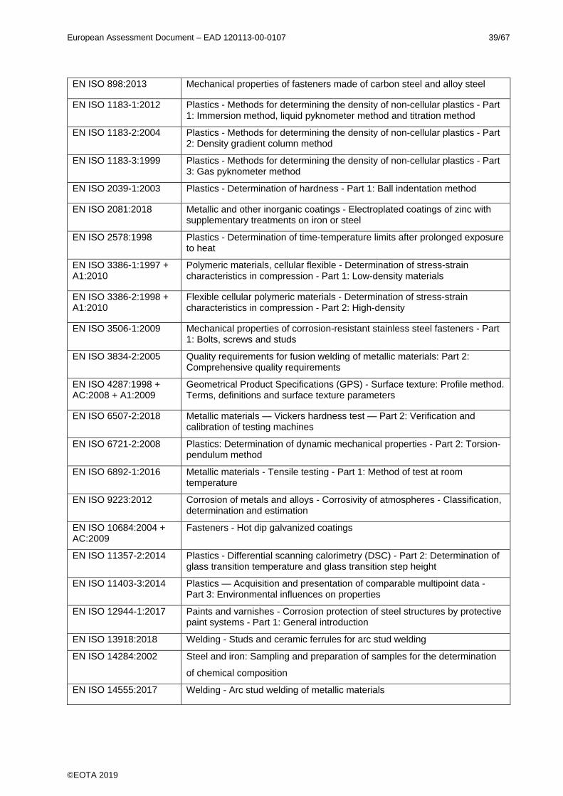
European Assessment Document – EAD 120113-00-0107 39/67
©EOTA 2019
EN ISO 898:2013 Mechanical properties of fasteners made of carbon steel and alloy steel
EN ISO 1183-1:2012 Plastics - Methods for determining the density of non-cellular plastics - Part 1: Immersion method, liquid pyknometer method and titration method
EN ISO 1183-2:2004 Plastics - Methods for determining the density of non-cellular plastics - Part 2: Density gradient column method
EN ISO 1183-3:1999 Plastics - Methods for determining the density of non-cellular plastics - Part 3: Gas pyknometer method
EN ISO 2039-1:2003 Plastics - Determination of hardness - Part 1: Ball indentation method
EN ISO 2081:2018 Metallic and other inorganic coatings - Electroplated coatings of zinc with supplementary treatments on iron or steel
EN ISO 2578:1998 Plastics - Determination of time-temperature limits after prolonged exposure to heat
EN ISO 3386-1:1997 + A1:2010
Polymeric materials, cellular flexible - Determination of stress-strain characteristics in compression - Part 1: Low-density materials
EN ISO 3386-2:1998 + A1:2010
Flexible cellular polymeric materials - Determination of stress-strain characteristics in compression - Part 2: High-density
EN ISO 3506-1:2009 Mechanical properties of corrosion-resistant stainless steel fasteners - Part 1: Bolts, screws and studs
EN ISO 3834-2:2005 Quality requirements for fusion welding of metallic materials: Part 2: Comprehensive quality requirements
EN ISO 4287:1998 + AC:2008 + A1:2009
Geometrical Product Specifications (GPS) - Surface texture: Profile method. Terms, definitions and surface texture parameters
EN ISO 6507-2:2018 Metallic materials — Vickers hardness test — Part 2: Verification and calibration of testing machines
EN ISO 6721-2:2008 Plastics: Determination of dynamic mechanical properties - Part 2: Torsion-pendulum method
EN ISO 6892-1:2016 Metallic materials - Tensile testing - Part 1: Method of test at room temperature
EN ISO 9223:2012 Corrosion of metals and alloys - Corrosivity of atmospheres - Classification, determination and estimation
EN ISO 10684:2004 + AC:2009
Fasteners - Hot dip galvanized coatings
EN ISO 11357-2:2014 Plastics - Differential scanning calorimetry (DSC) - Part 2: Determination of glass transition temperature and glass transition step height
EN ISO 11403-3:2014 Plastics — Acquisition and presentation of comparable multipoint data - Part 3: Environmental influences on properties
EN ISO 12944-1:2017 Paints and varnishes - Corrosion protection of steel structures by protective paint systems - Part 1: General introduction
EN ISO 13918:2018 Welding - Studs and ceramic ferrules for arc stud welding
EN ISO 14284:2002 Steel and iron: Sampling and preparation of samples for the determination
of chemical composition
EN ISO 14555:2017 Welding - Arc stud welding of metallic materials

European Assessment Document – EAD 120113-00-0107 40/67
©EOTA 2019
EN ISO 14713-1:2017 Zinc coatings - Guidelines and recommendations for the protection against corrosion of iron and steel in structures - Part 1: General principles of design and corrosion resistance
ISO 34-1:2015 Rubber, vulcanized or thermoplastic - Determination of tear strength - Part 1: Trouser, angle and crescent test pieces
ISO 37:2017 Rubber, vulcanized or thermoplastic - Determination of tensile stress-strain properties
ISO 48-2:2018 Rubber, vulcanized or thermoplastic - Determination of hardness - Part 2: Hardness between 10 IRHD and 100 IRHD
ISO 48-4:2018 Rubber, vulcanized or thermoplastic - Determination of hardness - Part 4: Indentation hardness by durometer method (Shore hardness)
ISO 188:2011 Rubber, vulcanized or thermoplastic - Accelerated ageing and heat resistance tests
ISO 812:2017 Rubber, vulcanized or thermoplastic - Determination of low-temperature brittleness
ISO 813:2016 Rubber, vulcanized or thermoplastic - Determination of adhesion to a rigid substrate - 90° peel method
ISO 815-1:2014 Rubber, vulcanized or thermoplastic - Determination of compression set - Part 1: At ambient or elevated temperatures
ISO 1431-1:2012 Rubber, vulcanized or thermoplastic - Resistance to ozone cracking - Part 1: Static and dynamic strain testing
ISO 1817:2015 Rubber, vulcanized or thermoplastic - Determination of the effect of liquids
ISO 1827:2016 Rubber, vulcanized or thermoplastic - Determination of shear modulus and adhesion to rigid plates - Quadruple-shear methods
ISO 2781:2018 Rubber, vulcanized or thermoplastic - Determination of density
ISO 2039-1:2001 Plastics: Determination of hardness - Part 1: Ball indentation method
ISO 9924-1:2016 Rubber and rubber products - Determination of the composition of vulcanizates and uncured compounds by thermogravimetry - Part 1: Butadiene, ethylene-propylene copolymer and terpolymer, isobutene-isoprene, isoprene and styrene-butadiene rubbers
ISO 9924-3:2009 Rubber and rubber products - Determination of the composition of vulcanizates and uncured compounds by thermogravimetry - Part 3: Hydrocarbon rubbers, halogenated rubbers and polysiloxane rubbers after extraction
EOTA TR034 General BWR3 Checklist for EADs/ETAs - Dangerous substances
EAD 120109-00-0107 Nosing expansion joints for road bridges
EAD 120111-00-0107 Cantilever expansion joints for road bridges
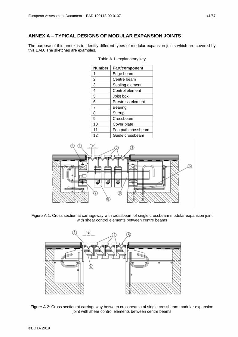
European Assessment Document – EAD 120113-00-0107 41/67
©EOTA 2019
ANNEX A – TYPICAL DESIGNS OF MODULAR EXPANSION JOINTS
The purpose of this annex is to identify different types of modular expansion joints which are covered by this EAD. The sketches are examples.
Table A.1: explanatory key
Number Part/component
1 Edge beam
2 Centre beam
3 Sealing element
4 Control element
5 Joist box
6 Prestress element
7 Bearing
8 Stirrup
9 Crossbeam
10 Cover plate
11 Footpath crossbeam
12 Guide crossbeam
Figure A.1: Cross section at carriageway with crossbeam of single crossbeam modular expansion joint with shear control elements between centre beams
Figure A.2: Cross section at carriageway between crossbeams of single crossbeam modular expansion joint with shear control elements between centre beams
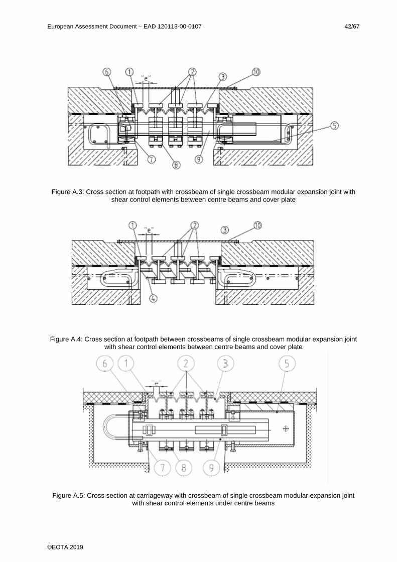
European Assessment Document – EAD 120113-00-0107 42/67
©EOTA 2019
Figure A.3: Cross section at footpath with crossbeam of single crossbeam modular expansion joint with shear control elements between centre beams and cover plate
Figure A.4: Cross section at footpath between crossbeams of single crossbeam modular expansion joint with shear control elements between centre beams and cover plate
Figure A.5: Cross section at carriageway with crossbeam of single crossbeam modular expansion joint with shear control elements under centre beams
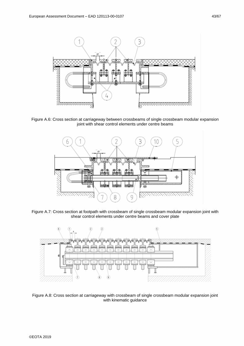
European Assessment Document – EAD 120113-00-0107 43/67
©EOTA 2019
Figure A.6: Cross section at carriageway between crossbeams of single crossbeam modular expansion joint with shear control elements under centre beams
Figure A.7: Cross section at footpath with crossbeam of single crossbeam modular expansion joint with shear control elements under centre beams and cover plate
Figure A.8: Cross section at carriageway with crossbeam of single crossbeam modular expansion joint with kinematic guidance
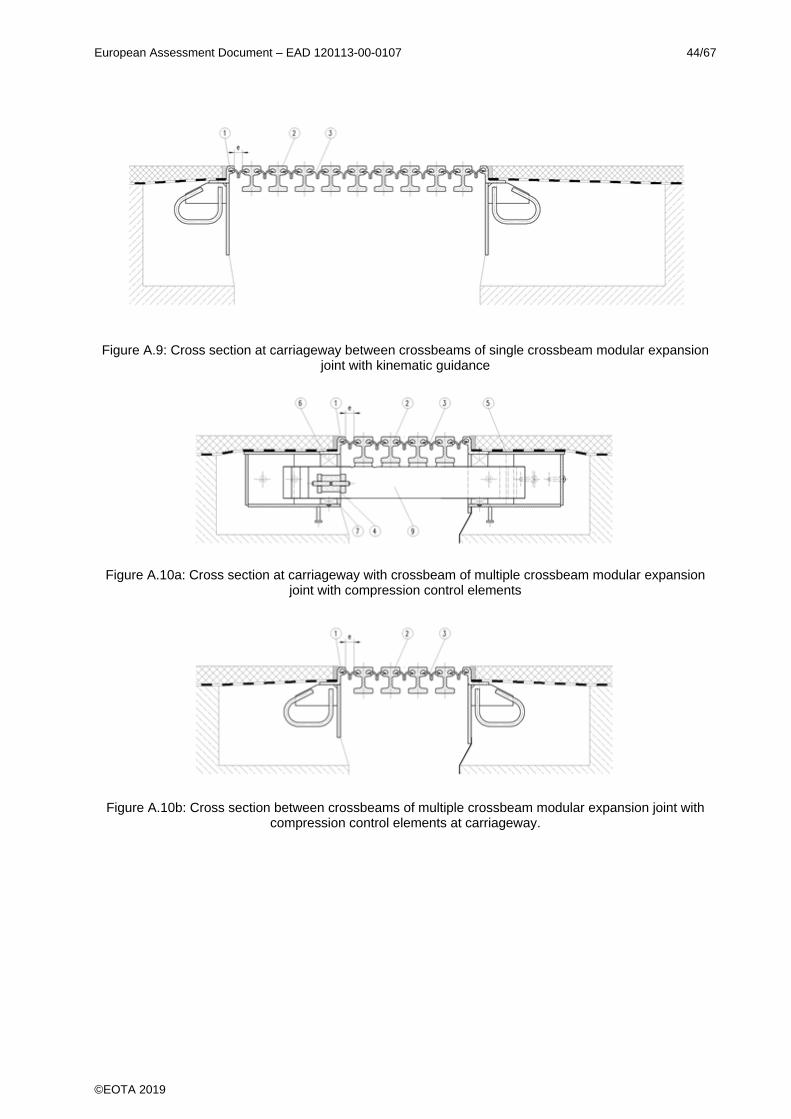
European Assessment Document – EAD 120113-00-0107 44/67
©EOTA 2019
Figure A.9: Cross section at carriageway between crossbeams of single crossbeam modular expansion joint with kinematic guidance
Figure A.10a: Cross section at carriageway with crossbeam of multiple crossbeam modular expansion joint with compression control elements
Figure A.10b: Cross section between crossbeams of multiple crossbeam modular expansion joint with compression control elements at carriageway.
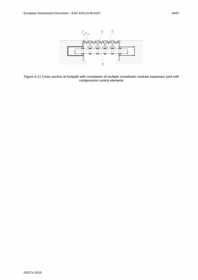
European Assessment Document – EAD 120113-00-0107 45/67
©EOTA 2019
Figure A.11 Cross section at footpath with crossbeam of multiple crossbeam modular expansion joint with compression control elements
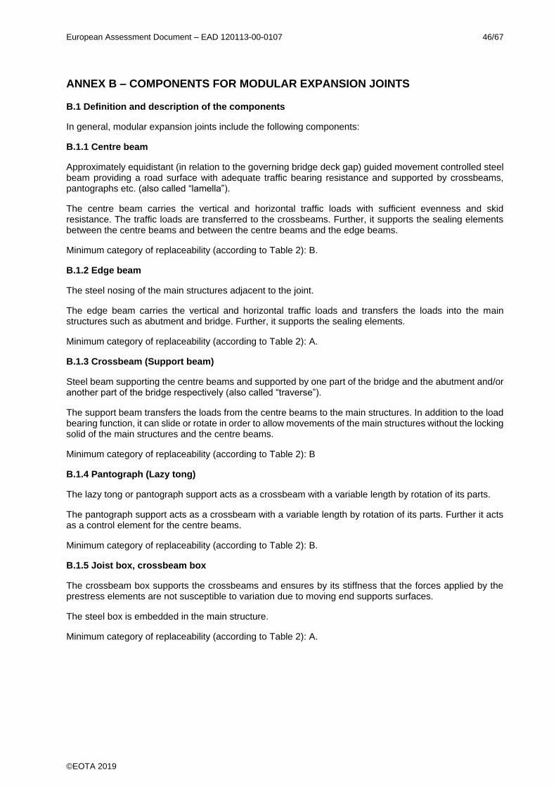
European Assessment Document – EAD 120113-00-0107 46/67
©EOTA 2019
ANNEX B – COMPONENTS FOR MODULAR EXPANSION JOINTS
B.1 Definition and description of the components
In general, modular expansion joints include the following components:
B.1.1 Centre beam
Approximately equidistant (in relation to the governing bridge deck gap) guided movement controlled steel beam providing a road surface with adequate traffic bearing resistance and supported by crossbeams, pantographs etc. (also called “lamella”).
The centre beam carries the vertical and horizontal traffic loads with sufficient evenness and skid resistance. The traffic loads are transferred to the crossbeams. Further, it supports the sealing elements between the centre beams and between the centre beams and the edge beams.
Minimum category of replaceability (according to Table 2): B.
B.1.2 Edge beam
The steel nosing of the main structures adjacent to the joint.
The edge beam carries the vertical and horizontal traffic loads and transfers the loads into the main structures such as abutment and bridge. Further, it supports the sealing elements.
Minimum category of replaceability (according to Table 2): A.
B.1.3 Crossbeam (Support beam)
Steel beam supporting the centre beams and supported by one part of the bridge and the abutment and/or another part of the bridge respectively (also called “traverse”).
The support beam transfers the loads from the centre beams to the main structures. In addition to the load bearing function, it can slide or rotate in order to allow movements of the main structures without the locking solid of the main structures and the centre beams.
Minimum category of replaceability (according to Table 2): B
B.1.4 Pantograph (Lazy tong)
The lazy tong or pantograph support acts as a crossbeam with a variable length by rotation of its parts.
The pantograph support acts as a crossbeam with a variable length by rotation of its parts. Further it acts as a control element for the centre beams.
Minimum category of replaceability (according to Table 2): B.
B.1.5 Joist box, crossbeam box
The crossbeam box supports the crossbeams and ensures by its stiffness that the forces applied by the prestress elements are not susceptible to variation due to moving end supports surfaces.
The steel box is embedded in the main structure.
Minimum category of replaceability (according to Table 2): A.

European Assessment Document – EAD 120113-00-0107 47/67
©EOTA 2019
B.1.6 Sealing element
A flexible element which ensures the watertightness of the expansion joint and protects it against debris and does not carry traffic loads.
This EAD applies for sealing elements made of elastomer based on Polychloroprenerubber (CR), Ethylene-Propylene-Diene Material (EPDM), Styrol-Butadiene-Rubber (SBR) or mixture of SBR, CR and NR.
Minimum category of replaceability (according to Table 2): C.
B.1.7 Seal clamping device
The clamping device is defined as element for fixing the sealing element. The clamping devices can be integrated in the seals.
Minimum category of replaceability (according to Table 2) is depending on its use defined by the manufacturer.
B.1.8 Bearing
Element transferring the (traffic and prestress) loads from the centre beam to the crossbeam and/or to the main structure.
The bearing transfers the (traffic) loads from the centre beam to the crossbeam and/or to the main structure. The bearing can be fixed or sliding, in all cases it enables rotations. Rotations can cause reaction moments from deformation or friction in curved sliding surfaces.
Bearings according to this EAD are made of elastomers (based on Polychloroprenerubber (CR), Ethylene-Propylene-Diene Material (EPDM), Styrol-Butadiene-Rubber (SBR), Natural rubber (NR) or mixture of SBR, CR and NR) or plastics (Polyamide, Polyoxymethylene, Polyethylene (including UHMWPE)) possibly with steel inserts, eventually with polymer sliding surfaces.
Bearings transfer vertical loads, accommodating translations and rotations. The Loading conditions are Static (prestress) and dynamic (traffic) loads. Depending on the detailing, sliding and imposed rotations can take place and shear forces can occur.
Minimum category of replaceability (according to Table 2): C.
The bearings shall be included in the test procedure of:
• Load bearing test with creep and relaxation, according to Annex C.
• Friction test (translation and/or rotation) according to Annex D
• Wear test (translation and/or rotation) according to Annex D
• Fatigue test according to Annex D
B.1.9 Prestress element
A prestress element prevents uplift of the centre beam to crossbeam connection and/or uplift in the crossbeam to main structure connection. A prestress element can be fixed or sliding and always has to allow rotations. Rotations can cause reaction moments from deformation or friction in curved sliding surfaces.
The prestress elements transfer forces generated by imposed prestress (Static) and traffic loads (Dynamic).
The prestress elements are made of NR or CR-with steel inserts, eventually with PTFE or other sliding surfaces.
Minimum category of replaceability (according to Table 2): C.
The prestress elements shall be included in the test procedure of:
• Load bearing test with creep and relaxation, according to Annex C.
• Friction test (translation and/or rotation) according to Annex D

European Assessment Document – EAD 120113-00-0107 48/67
©EOTA 2019
• Wear test (translation and/or rotation) according to Annex D
• Fatigue test according to Annex D
B.1.10 Control element
Element ensuring that the centre beams are at approximately equal distances at the various opening positions of the modular expansion joints.
Control elements ensure that the centre beams are at approximately equal distances at the various opening positions of the modular joints.
Minimum category of replaceability (according to Table 2): C.
The control elements transfer horizontal loads.
The control elements are made of NR and CR with vulcanised steel parts or thermoplastic elastomer, steel parts in mechanical structures dynamically loaded.
The control elements shall be included in the test procedure of:
• Load bearing test with creep and relaxation, according to Annex C if subject to constant load or deformation.
• Wear test (translation and/or rotation) according to Annex D if subject to wear
• Fatigue test according to Annex D if subject to traffic loads
B.1.11 Anchorage system
Steel bars and/or rods that connect the modular expansion joint to the main structure or the abutment.
Minimum category of replaceability (according to Table 2): A.
B.1.12 Additional surface elements (e.g. noise reducing elements)
Steel surface elements reducing the noise of traffic on the joint.
Minimum category of replaceability (according to Table 2): B.
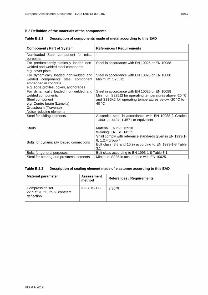
European Assessment Document – EAD 120113-00-0107 49/67
©EOTA 2019
B.2 Definition of the materials of the components
Table B.2.1 Description of components made of metal according to this EAD
Table B.2.2 Description of sealing element made of elastomer according to this EAD
Component / Part of System References / Requirements
Non-loaded Steel component for misc. purposes
-
For predominantly statically loaded non-welded and welded steel component e.g. cover plate
Steel in accordance with EN 10025 or EN 10088
For dynamically loaded non-welded and welded components steel component embedded in concrete e.g. edge profiles, boxes, anchorages
Steel in accordance with EN 10025 or EN 10088 Minimum: S235J2
For dynamically loaded non-welded and welded components Steel component e.g. Centre beam (Lamella) Crossbeam (Traverse) Noise reducing elements
Steel in accordance with EN 10025 or EN 10088 Minimum S235J2 for operating temperatures above -20 °C and S235K2 for operating temperatures below -20 °C to -40 °C
Steel for sliding elements Austenitic steel in accordance with EN 10088-2 Grades 1.4401, 1.4404, 1.4571 or equivalent
Studs Material: EN ISO 13918 Welding: EN ISO 14555
Bolts for dynamically loaded connections
Shall comply with reference standards given in EN 1993-1-8, 1.2.4 group 4 Bolt class (8.8 and 10.9) according to EN 1993-1-8 Table 3.1
Bolts for general purposes Bolt class according to EN 1993-1-8 Table 3.1
Steal for bearing and prestress elements Minimum S235 in accordance with EN 10025
Material parameter Assessment method
References / Requirements
Compression set 22 h at 70 °C, 25 % constant deflection
ISO 815-1 B 30 %
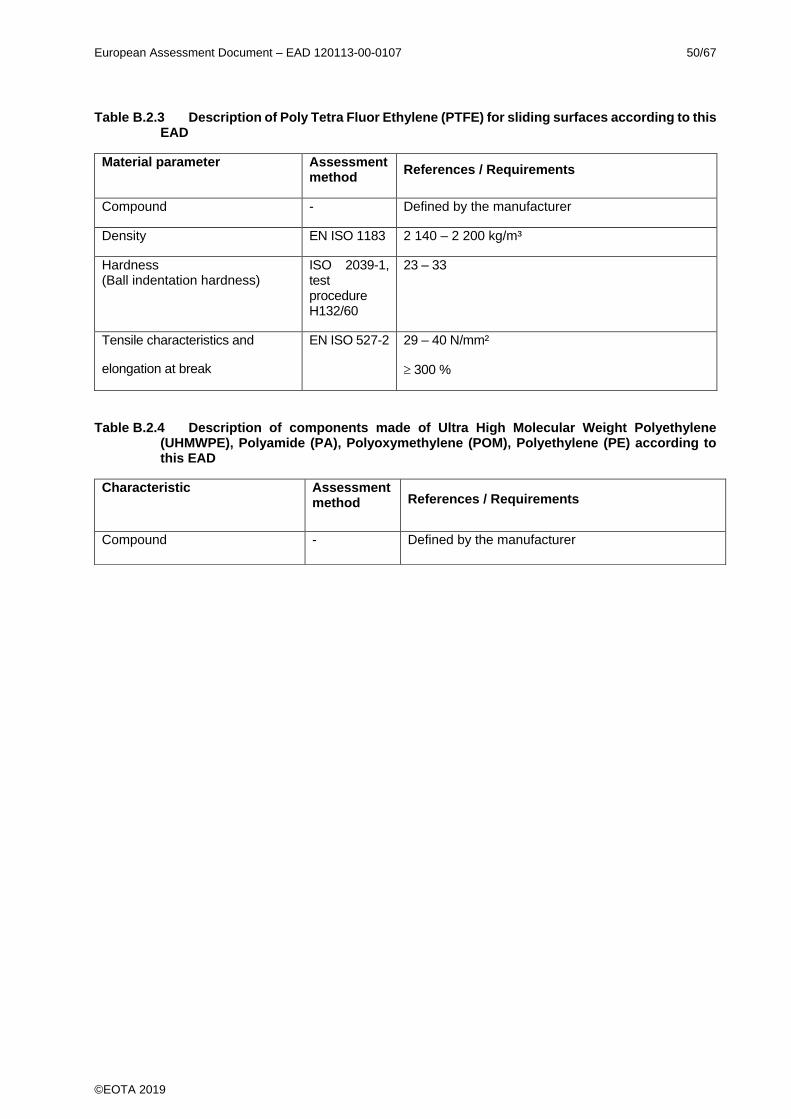
European Assessment Document – EAD 120113-00-0107 50/67
©EOTA 2019
Table B.2.3 Description of Poly Tetra Fluor Ethylene (PTFE) for sliding surfaces according to this EAD
Table B.2.4 Description of components made of Ultra High Molecular Weight Polyethylene (UHMWPE), Polyamide (PA), Polyoxymethylene (POM), Polyethylene (PE) according to this EAD
Material parameter Assessment method
References / Requirements
Compound - Defined by the manufacturer
Density EN ISO 1183 2 140 – 2 200 kg/m³
Hardness (Ball indentation hardness)
ISO 2039-1, test procedure H132/60
23 – 33
Tensile characteristics and
elongation at break
EN ISO 527-2 29 – 40 N/mm²
300 %
Characteristic Assessment method References / Requirements
Compound - Defined by the manufacturer

European Assessment Document – EAD 120113-00-0107 51/67
©EOTA 2019
ANNEX C – STATIC TESTING – MECHANICAL RESISTANCE OF THE PRODUCT REPRESENTED BY TEST METHOD FOR COMPONENTS
C.1 Scope
This annex describes the testing method for assessing the mechanical resistance of the product represented by components for modular joints in relation to ULS and SLS load combinations, giving consideration to creep and relaxation where relevant.
C.2 Principles
The principle of this test is that a component is subjected to a load configuration (or imposed deformation) derived from the relevant static load combinations. The boundary conditions are modified in time so as to integrate creep and relaxation in one testing procedure, where relevant.
C.3 Samples and preparation of test specimens
One specimen of each type has to be tested.
If there is a range with the same type, then take one test at each border of the range and one test in the middle of the range.
The test specimen shall be full-scale components.
The preparation of the test specimen is under the responsibility of the manufacturer.
C.4 Load arrangements
The component related load and deformation arrangements on the specimens shall be derived from the appropriate load combinations (including the partial factors) as given in EAD 120109-00-0107, Annex D, Clause D.2.4.2. The test load shall include the prestress effect Fik, if any, and predicted creep and relaxation effects.
C.5 Testing arrangement and conditions
The component shall be mounted in a test frame in order to ensure that the imposed loads, deformations and rotations (which can be achieved using wedges) are compatible with the most adverse position for the as-built situation. The test frame shall be suitable to allow the build up of the forces during all test phases, and, if desired, to allow the impose deformations and rotations if needed.
The temperature of testing shall be between +15°C and +45°C.
If the mechanical properties of the material are affected by the temperature variation, this variation has to be defined in such a way that the properties for other temperatures can be derived by calculation.
C.6 Execution of the test
Due attention shall be given to rotations, eccentricities, imposed deformations and constraint effects, if they affect the load transfer at the sliding surfaces and through the component.
For creep testing, due attention shall be given to the continuous long-term load and the accuracy of the measuring equipment.
Phases 1 – 2 do not necessarily need to be carried out in the same testing rig with the same equipment as the phases 3 – 6 as given in Table C.1.
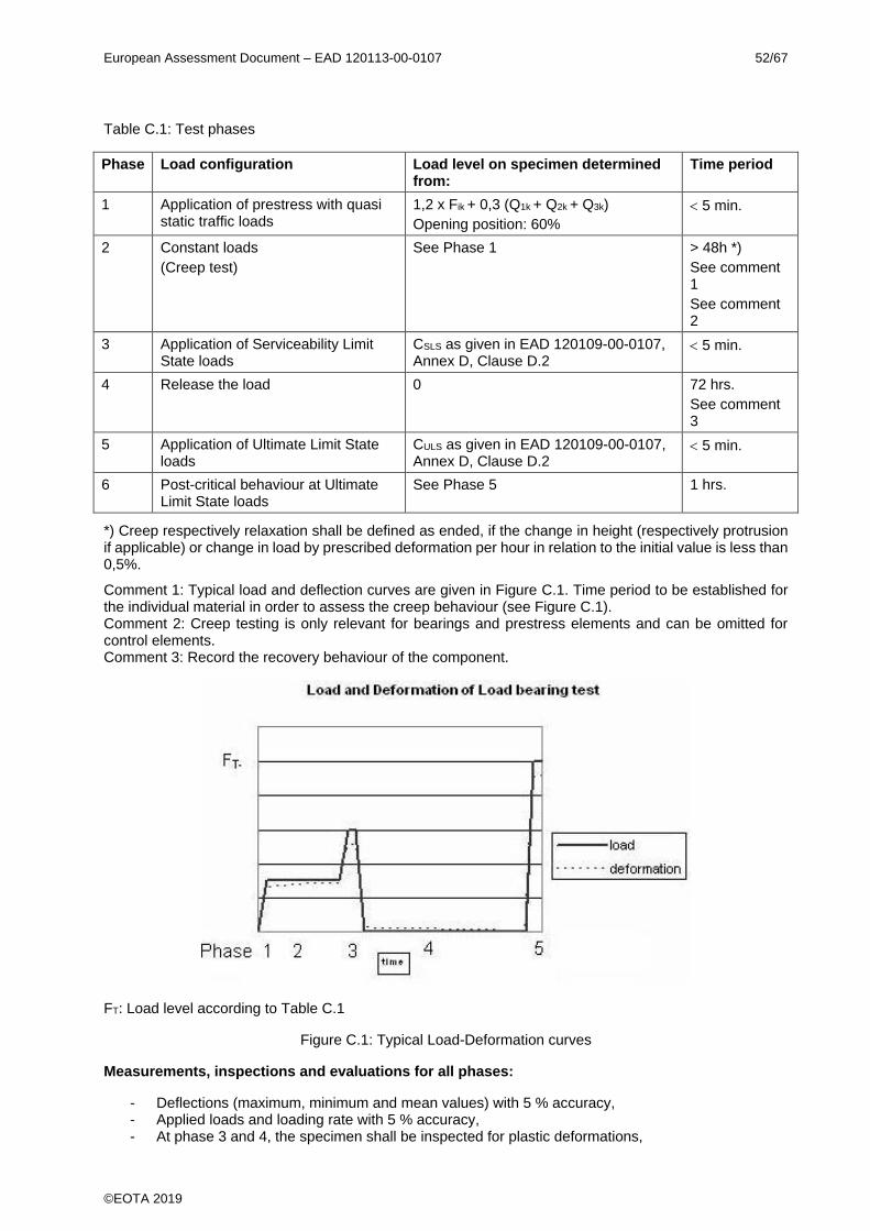
European Assessment Document – EAD 120113-00-0107 52/67
©EOTA 2019
Table C.1: Test phases
Phase Load configuration Load level on specimen determined from:
Time period
1 Application of prestress with quasi static traffic loads
1,2 x Fik + 0,3 (Q1k + Q2k + Q3k)
Opening position: 60%
5 min.
2 Constant loads
(Creep test)
See Phase 1 > 48h *)
See comment 1
See comment 2
3 Application of Serviceability Limit State loads
CSLS as given in EAD 120109-00-0107, Annex D, Clause D.2
5 min.
4 Release the load 0 72 hrs.
See comment 3
5 Application of Ultimate Limit State loads
CULS as given in EAD 120109-00-0107, Annex D, Clause D.2
5 min.
6 Post-critical behaviour at Ultimate Limit State loads
See Phase 5 1 hrs.
*) Creep respectively relaxation shall be defined as ended, if the change in height (respectively protrusion if applicable) or change in load by prescribed deformation per hour in relation to the initial value is less than 0,5%.
Comment 1: Typical load and deflection curves are given in Figure C.1. Time period to be established for the individual material in order to assess the creep behaviour (see Figure C.1). Comment 2: Creep testing is only relevant for bearings and prestress elements and can be omitted for control elements. Comment 3: Record the recovery behaviour of the component.
FT: Load level according to Table C.1
Figure C.1: Typical Load-Deformation curves
Measurements, inspections and evaluations for all phases:
- Deflections (maximum, minimum and mean values) with 5 % accuracy, - Applied loads and loading rate with 5 % accuracy, - At phase 3 and 4, the specimen shall be inspected for plastic deformations,

European Assessment Document – EAD 120113-00-0107 53/67
©EOTA 2019
- Creep ratio with 5 % accuracy, - Debonding effects, if any, - Cracks, if any, - Exceptional behaviour, - Failure mode, if any, - Determine the load-deflection curves.
C.7 Assessment
In terms of assessment criteria given in Table 4 the following applies:
- The measured deformations, creep and relaxation shall not influence the performance of the kit in a negative way.
- No plastic deformations at SLS level (plastic behaviour not influencing the performance of the kit in negative way allowed).
- Cracks and/or debonding effects at ULS shall not cause damage to the joint. - No brittle behaviour at ULS.
C.8 Test report
The test report shall include at least the following:
- Name of the manufacturer and production centre, - Name and signature of testing body, - Model identification (type, theoretical movement capacity, N° of batch), - Drawings, - Material specifications, - Reference to this annex, - Description of the test equipment, - Date of the preparation of specimens, the date of test and the test temperature, - Dimensions of test specimens, - Report of observed phenomena according to C.6 and C.7, - Photos of relevant components and test set up at least before and after testing situations.

European Assessment Document – EAD 120113-00-0107 54/67
©EOTA 2019
ANNEX D – DYNAMIC TESTING – RESISTANCE TO FATIGUE AND WEAR OF THE PRODUCT REPRESENTED BY COMPONENTS
D.1 Scope
This annex describes the method for assessing the resistance to fatigue and wear of the product represented by components for modular expansion joints. The test method includes the effects of the accumulation of wear of the sliding surfaces.
D.2 Principles
The principle of this test is to apply movement (Phase 1) and load cycles (Phase 2) on the components. The movements and loads are derived from reference movements and loads considered as simulations of movements and traffic loads in practice.
Hereafter, a general dynamic testing procedure is described. Analysis of the load transfer of the joint shall indicate whether all tests have to be carried out or whether specific phases shall be disregarded.
D.3 Samples and preparation of test specimens
One specimen of each type has to be tested.
If there is a range with the same type, then take one test at each border of the range and one test in the middle of the range.
The specimen shall be full-scale components.
The preparation of the test specimen is under the responsibility of the manufacturer.
D.4 Movement and load arrangements
The component related load and deformation arrangements on the specimens shall be derived from the appropriate load combinations (including the partial factors) as given in EAD 120109-00-0107, Annex D, Clause D.2.4.2.
D.4.1 Bridge movement due to temperature on the bridge (Phase 1)
The total slide path for the test procedure in relation to a working life of “a” years of a component is derived from:
a x 365 x 0,33 x maximum movement capacity = 120 x a cycles with maximum movement capacity of the joint.
For Working life categories B and C: a ≥ 10.
The wear test on the component shall be carried out with the prestress of the built-in component taking account of creep and relaxation if any.
D.4.2 Traffic loads (Phase 2)
Depending on the composition of the components, a choice shall be made between applied loads derived from FLM1EJ or FLM2EJ. The loads shall be applied for the most adverse boundary conditions in conjunction with a 60 % opening position of the joint.
1. Fatigue Load Model for expansion joints FLM1EJ to assess an unlimited life with respect to fatigue.
The test parameters shall be derived from:
- Vertical axle load: fat(1). 0,7.Q1k =1,3 x 0,7 x 300 = 273 kN
- Horizontal axle load: fath 0,7.0,2.Q1k =1,0 x 0,7 x 0,2 x 300 = 42 kN - Minimum number of cycles: 5 x 10⁶
- Wheel print l x b (mm): 300 x 250
European Assessment Document – EAD 120113-00-0107 55/67
©EOTA 2019
1) The dynamic amplification factor can be reduced based on field tests according to Annex E.
or:
2. Fatigue Load Model for expansion joints FLM2EJ to establish an S-N relationship from which a related working life category according to Clause 1.2.2 can be derived.
The test parameters shall be derived from the distribution and the combinations of vertical and horizontal axles loads as given in EAD 120109-00-0107, Annex D, Table D.5.
The dynamic amplification factor, included as a factor 1,3 in the axle loads of EAD 120109-00-0107, Annex D, Table D.5, can be reduced based on field tests.
The test loads for fatigue include a partial factor Ff = 1,0.
D.5 Execution of the test
A specimen shall be subjected to Phase 1 and subsequently to Phase 2 if the component representative for the kit is subject to sliding.
Due attention shall be given to rotations, eccentricities, imposed deformations and constraint effects, if they affect the load transfer at the sliding surfaces and through the component.
Phase 1, wear and friction test
- Apply a load Fik with 5 % accuracy. - Apply cyclic movements with a minimum mean velocity of 4 mm/s on the test specimen. The
amplitudes shall be derived from amplitudes of 33 % of the total movement capacity of the joint (one complete cycle corresponds to 67 % of the total movement capacity of the joint).
- The required number of cycles is derived from the working life of the component. - The test shall be carried out at ambient temperature (between +5 °C and +35 °C). - If the temperature of the specimen exceeds 35 °C measured at the surface of the specimen, the
test may be interrupted.
Measurements during phase 1
- Measure the (initial) static and dynamic friction coefficients during 10 cycles, at the beginning of the test, at intervals of 1 000 m slide path and after every dwell period.
- Measure the wear of the specimen after each phase by weighing of the specimen and measuring the dimensions of the specimen before and after the test phases. Inspect the sliding surfaces.
Phase 2, Fatigue test
The test shall be carried out at ambient temperature (between +5 °C and +35 °C) and the test loads shall be derived for an opening position of the joint, which is 60 % of the maximum opening position of the joint.
Apply the cyclic loads resulting from a structural analysis in accordance with the procedure given in D.4.2 and, where relevant, consider the effect of preload on the component.
Note: Resulting loads can be: Compression only, Alternating or Tension only.
Approach 1, Unlimited fatigue life
If, after being subjected to 5 x 10⁶ cycles, the component has not collapsed or does not show damage, it can be assumed that the fatigue life of the component is unlimited.
Approach 2, Limited fatigue life
After being subjected to the relevant load cycles for the envisaged working life category and defined in EAD 120111-00-0107, Annex F, the component has not collapsed or does not show damage, it can be assumed that the fatigue life of the component is fulfilled for the selected working life category.

European Assessment Document – EAD 120113-00-0107 56/67
©EOTA 2019
D.6 Expression of the results
The following results shall be reported:
Phase 1
- The (initial) static and dynamic friction coefficients during 10 cycles, at the beginning of the test, at intervals of 1 000 m slide path and after every dwell period,
- The loss of mass of the specimen after each phase, the dimensions of the specimen before and after the test phases,
- The condition of the sliding surfaces, - Reaction forces during the test, - Deformations, - Debonding, - Cracking, - Displacements, - Changes in preload if any.
Phase 2
- Applied loads, - Deflection and deformations, - Cracks, - Exceptional behaviour, - Mode of failure, - Expected working life.
D.7 Test report
- The test report shall include at least the following: - Name of the manufacturer and production centre, - Name and signature of testing body, - Model identification (type, theoretical movement capacity, N° of batch), - Drawings, - Material specifications, - Reference to this annex, - Description of the test equipment, - Date of the preparation of specimens, the date of test and the test temperature, - Dimensions of test specimens, - Report of observed phenomena according to D.6, - Photos of relevant testing situations.

European Assessment Document – EAD 120113-00-0107 57/67
©EOTA 2019
ANNEX E - DYNAMIC ASSESSMENT AND FIELD TESTING
E.1 Introduction
A modular expansion joint is a kit, assembled from components. In addition, the field-testing allows the determination of the dynamic behaviour of the kit or single components of joints.
This annex describes how field tests of the kit shall be arranged and carried out and how the dynamic behaviour can be evaluated. Here, field-testing means that tests are carried out on full-scale joints which can be situated in an existing road or at testing facilities.
E.2 Objective
The objective of this test method is to derive the dynamic properties, dynamic factors for vertical and horizontal loads, system and material damping, free vibration, the (dynamic) loads for the kit and boundary conditions for the component testing, where necessary.
E.3 Principles
The principle of this test is that a full-scale joint is subjected to moving loads exerted by a reference lorry (over rolling test) and that the measurements, e.g. carried out by accelerometers, strain gauges and recordings of laser signals enable a proper dynamic analysis.
One test specimen, subjected to two passing test lorries with different speeds, is sufficient.
The results of the test and analyses apply for joints of the same type, but with other dimensions, provided the calculated vertical, horizontal and rotation natural frequencies do not fall below 90% of those of the originally tested and analysed expansion joint.
Dynamic amplifications and upswing shall be directly calculated from strains.
Simultaneously to the test, a 3-D (Finite Element) Model is established of the kit, which is used to derive natural frequencies and natural vectors to obtain knowledge and insight with which the performance of expansion joints with other numbers of sealing elements can be derived.
E.4 Scope and range of application
The evaluation of test results based on this annex is applicable for joints loaded by one axle in the traffic direction only (expansion joint width approximately 1 200 mm). For larger joints the test results can be used in conjunction with additional analyses.
The dynamic assessments described in this annex are based on joints positioned perpendicular to the traffic direction and perpendicular to the main axis of the bridge.
Joints not perpendicular to the traffic direction will show a smoother load application effect and therefore can be considered included. Skew joints are considered covered by investigations on perpendicular joints, if their dynamic properties are equal to perpendicular joints.
E.5 Samples and preparation of test specimens for over rolling tests
The test pieces shall be full-scale joints. The type, which is the most susceptible against dynamic influences, shall be tested (e.g. longest cantilever, worst relations of geometries).
A minimum of three centre beams with two cantilever parts. The centre-to-centre distance of the crossbeams shall be at least 80 % of the maximum theoretical value.
The evenness of the joint shall meet the manufacturer’s design specifications. The evenness of the adjacent pavement shall be of medium quality (See EN 1991-2, 4.2.1, Note 3).
One specimen of each type has to be tested.
The preparation of the test specimen is under the responsibility of the manufacturer.
European Assessment Document – EAD 120113-00-0107 58/67
©EOTA 2019
E.6 Testing arrangement and conditions
E.6.1 Location and conditions
The joint is located in a road and installed similarly to real “built-in” situations. The opening positions of the joint shall be at 60 % of movement capacity (middle position +/- 5 mm). The tests are carried out at ambient temperatures (between +5 °C and +35 °C).
E.6.2 Instrumentation
The instrumentation of the modular expansion joint shall consist of a combination of accelerometers, strain gauges and displacement sensors on e.g. edge profiles, cantilevers, centre beams and crossbeams (see Figure E.1).
The instrumentation shall allow a clear analysis of vertical bending, horizontal bending, torsion and/or tilting. The sampling frequency of the instrumentation shall allow a proper analysis of the dynamic behaviour. The accuracy of measured variable shall be at least 5% of the maximum measured value.
The vehicle (see E.7.2) does not need to be instrumented.
A minimum sampling frequency of 10 to 15 times the highest relevant natural frequency (e.g. 1 500 Hz) is recommended for the data acquisition. In addition a minimum sampling frequency shall correspond to 10 times the inverse of the loading time (equal to the sum of length of the wheel print and length of a single contact surface, divided by the vehicle speed).
E.6.3 Joint extremities (cantilevers) and other discontinuities
The joint extremities with cantilevering parts larger than 0,3 times the intermediate spans (free cantilevering parts etc.) and other discontinuities shall be assessed with additional accelerometers. The results (Frequencies, natural vectors, accelerations) shall be used for calibration of calculation models used for the assessments according to Clauses 2.2.1 and 2.2.2.
E.6.4 Centre beams
Three neighbouring centre beams shall be instrumented with strain gauges, the same span of each centre beam. The instrumented span should be the second to last. Each centre beam shall have three instrumented cross-sections with 4 strain gauges (see Figure E.1) (one near the support and one at midspan) in order to facilitate the derivation of vertical and horizontal bending moments in the cross sections. If the load transfer conditions for the over rolling vehicle are almost the same for each centre beam, the strains at the support locations only have to be measured at the middle centre beam (see Figure E.1). For practical reasons, the strain gauges at the support locations may be placed at a small distance from the support. In that case, the measurements shall be corrected for that.
Transverse position of the wheel: A - Maximum effect on centre beams (see Figure E.2)
At least one wheel of every axle (left or right) passes the midspan of the middle centre beam (of the three instrumented centre beams) with a tolerance of 10 % of the span length.
For braking and acceleration tests the horizontal displacement of the supports shall be measured.
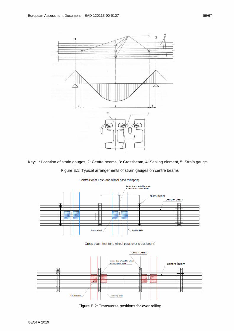
European Assessment Document – EAD 120113-00-0107 59/67
©EOTA 2019
Key: 1: Location of strain gauges, 2: Centre beams, 3: Crossbeam, 4: Sealing element, 5: Strain gauge
Figure E.1: Typical arrangements of strain gauges on centre beams
Figure E.2: Transverse positions for over rolling
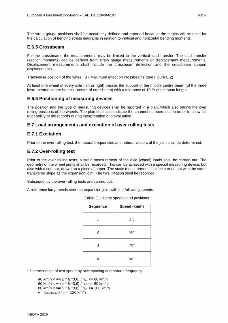
European Assessment Document – EAD 120113-00-0107 60/67
©EOTA 2019
The strain gauge positions shall be accurately defined and reported because the strains will be used for the calculation of bending stress diagrams in relation to vertical and horizontal bending moments.
E.6.5 Crossbeam
For the crossbeams the measurements may be limited to the vertical load transfer. The load transfer (section moments) can be derived from strain gauge measurements or displacement measurements. Displacement measurements shall include the crossbeam deflection and the crossbeam support displacements.
Transverse position of the wheel: B - Maximum effect on crossbeams (see Figure E.2)
At least one wheel of every axle (left or right) passes the support of the middle centre beam (of the three instrumented centre beams - centre of crossbeam) with a tolerance of 10 % of the span length
E.6.6 Positioning of measuring devices
The position and the type of measuring devices shall be reported in a plan, which also shows the over rolling positions of the wheels. The plan shall also indicate the channel numbers etc. in order to allow full traceability of the records during interpretation and evaluation.
E.7 Load arrangements and execution of over rolling tests
E.7.1 Excitation
Prior to the over rolling test, the natural frequencies and natural vectors of the joint shall be determined.
E.7.2 Over-rolling test
Prior to the over rolling tests, a static measurement of the axle (wheel) loads shall be carried out. The geometry of the wheel prints shall be recorded. This can be achieved with a special measuring device, but also with a contour, drawn on a piece of paper. The static measurement shall be carried out with the same transverse slope as the expansion joint. The tyre inflation shall be recorded.
Subsequently the over-rolling tests are carried out:
A reference lorry travels over the expansion joint with the following speeds:
Table E.1: Lorry speeds and positions
Sequence Speed (km/h)
1 5
2 50*
3 70*
4 90*
* Determination of test speed by axle spacing and natural frequency
40 km/h < v=(ai * f1 *3,6) / nv2 <= 60 km/h 60 km/h < v=(ai * f1 *3,6) / nv3 <= 80 km/h 80 km/h < v=(ai * f1 *3,6) / nv4 <= 100 km/h v = lwheel print x f1 <= 120 km/h
European Assessment Document – EAD 120113-00-0107 61/67
©EOTA 2019
Where ai [m] minimum axle spacing of the test lorry
f1 [Hz] first natural frequency (in vertical and/or horizontal direction) nv2, nv3, nv4 integer lwheel print length of the wheel print v Lorry speed [km/h]
Sequence 1 simulates a static load transfer through the joint. Sequences 2 – 4 generate dynamic load transfer through the joint.
For each speed and each transverse position, the number of over-rolling with the vehicle is at least 3.
At least one wheel of every axle (left or right) passes the midspan of the field with a tolerance of 10 % of the span length.
The vehicle speeds may be achieved by cruise control or manually and shall be recorded.
The (transverse) position of the over rolling wheels and the distances to the centre beam supports shall be reported.
The centre-to-centre distances and the width of the centre beam flanges shall be reported (gap width).
The as-built drawings of the joint (and its components) are part of the documentation of the test set up.
The following lorry types are recommended:
- Two axle lorry with axle loads as EN 1991-2 FLM4 Type 1: Front axle 70 kN and rear axle 130 kN. - Five axle lorry with axle loads as EN 1991-2 FLM4 Type 3: Tractor: Front axle 70 kN, Rear axle
150 kN, Trailer tridem 3 x 90 kN.
E.7.3 Braking and acceleration tests
The braking test is carried out for the investigation of maximum braking effects on the joint and the acceleration test is carried out for the investigation of maximum acceleration effects on the joint.
A reference lorry travels over the expansion joint with the following speeds:
Table E.2: Lorry speeds and positions
Sequence Start/End speed (km/h) Movement type
1 70/0 Braking
2 0/irrelevant Accelerating
Braking:
The lorry shall have a speed of 70 ( 5) km/h and braking with a minimum deceleration of 4 m/s2 is initiated at a distance between 10 and 5 m before the joint. The ABS system of the lorry shall be switched off. Further details of testing and lorry characteristics as E.7.2.
Accelerating:
The lorry starts with the driven axle at a distance of 2 m before the joint and is brought to full acceleration. Further details of testing and lorry characteristics as E.7.2.
For braking and accelerating for each transverse positon the number of over-rolling with the vehicle shall be taken from EN 1990, Annex D, at least 3.
E.8 Measurements and analyses
The following aspects shall be measured for further interpretation.
European Assessment Document – EAD 120113-00-0107 62/67
©EOTA 2019
E.8.1 Lorry
1. Wheel print geometry (static) (5% accuracy), 2. Tyre pressures (5% accuracy), 3. Travelling speed of the lorry above the joint (continuous, braking or accelerating) (5% accuracy),
4. Travelling position in transverse direction (10% accuracy).
E.8.2 Expansion joint
The following shall be measured:
1. Beam width, 2. Gap width (5% accuracy), 3. Strains (with gauge) (5% accuracy), 4. Accelerations (5% accuracy), 5. Distance (with laser) (5% accuracy).
Interference effects and phase shifts between vertical, horizontal and rotation movements shall be filtered, prior to further analysis.
E.8.3 Over-rolling tests
E.8.3.1 Effects in the vertical plane
E.8.3.1.1 Initial dynamic impact factor
The vertical dynamic impact factor fat of the centre beam shall be derived from the vertical section moments. The section moments at the supports and midspan shall be derived from the section moments at the strain gauge locations, taking into account the transversely distributed load introduced by the wheel print and offsets, if relevant. The support and midspan moments shall be summed for the determination of
the dynamic impact factors. The vertical dynamic impact factor fat [ - ] for the considered velocity is the vertical moment interval (sum of support and midspan moments) for sequence “i” MSvi [kNm], divided by the vertical moment interval for sequence 1 (v = 0) MSv0 [kNm].
Analysis:
- Vertical support moment: Msv [kNm], - Vertical midspan moment: Mmv [kNm], - Vertical moment interval: MSv = Msv + Mmv [kNm], - Vertical moment interval static: MSv0 [kNm],
- Vertical moment interval at sequence “i” with (v 0): MSvi [kNm],
- Dynamic impact factor: fat = MSvi/MSv0 ≥ 1.0. The dynamic impact factor shall be calculated with the 95%-fractile of the test results.
E.8.3.1.2 Upswing
Derive in the same way the vertical moment interval (MSvu [kNm] = Msvu [kNm] + Mmvu [kNm]) after unloading.
The vertical upswing ratio Uv = MSvu/MSv [-]
The vertical upswing ratio shall be calculated with the 95%-fractile of the test results.
E.8.3.1.3 Combined dynamic vertical effect
The dynamic load (moment etc.) design interval (Ed,dyn) to be used for fatigue assessments shall be based on:
Edv,dyn = Edv0 x fat x (1 + Uv) [Nm]
European Assessment Document – EAD 120113-00-0107 63/67
©EOTA 2019
E.8.3.2 Effects in the horizontal plane
The horizontal transfer factor “tr” (including traction, “rolling friction” and dynamic impact effects) of the centre beam shall be derived from the horizontal section moments for a travelling lorry and the vertical section moments for a standing lorry. The section moments at the support and midspan shall be derived from the section moments at the strain gauge locations, taking into account the transversely distributed load introduced by the wheel print. The support and midspan moments shall be summed for the determination of the transfer factor. The transfer factor “tr” for the considered velocity is the measured horizontal moment interval for sequence “i” MSh, divided by the vertical MSv0.
Analysis:
- Vertical support moment for a static load (v=0km/h): Msv0 [kNm], - Vertical midspan moment for a static load (v=0km/h): Mmv0 [kNm], - Vertical moment interval for a static load (v=0km/h): MSv0 = Msv0 + Mmv0 [kNm], - Horizontal support moment for a moving load at velocity i: Mshi [kNm], - Horizontal midspan moment for a moving load at velocity I: Mmhi [kNm], - Horizontal moment interval for a moving load (vi > 0km/h): MShi = Mshi + Mmhi [kNm],
- Transfer factor V/H incl. fat: tr = MShi/MSv0 [-]. The transfer factor shall be calculated with the 95%-fractile of the test results.
E.8.3.3 Response ratio
Derive in the same way the vertical moment interval (MSvu = Msvu + Mmvu) after unloading.
The horizontal response ratio Uh = MShu/MSh [-].
Without further analyses Uh shall be taken as 1,0.
E.8.3.4 Combined dynamic vertical effect
The dynamic load (moment etc.) design interval (Edh,dyn) to be used for fatigue assessments shall be based on:
Edh,dyn = Edh0 x fat x (1 + Uh) [kN]
E.8.4 Braking and acceleration tests
Analyses of the braking and acceleration tests can be used for calibration purposes of the braking forces to be used for ULS and a more detailed approach of the horizontal load introduction at ULS.
E.8.4.1 Braking test
From the horizontal bending moments in the instrumented centre beams the horizontal load introduction can be derived. The “fictitious” horizontal spring stiffness of the joint can be derived from the horizontal load and the horizontal displacements.
E.8.4.2 Acceleration test
From the horizontal bending moments in the instrumented centre beams the horizontal load introduction can be derived. The “fictitious” horizontal spring stiffness of the joint can be derived from the horizontal load and the horizontal displacements.
E.8.4.3 Rotation effects
Based on an analysis, the rotation effects may not be relevant for specific types of modular expansion joints. If not relevant (e.g. beam grid joints with welded connections between the centre beams and crossbeams), the measurements may be omitted.
The rotation effects shall be derived from displacement measurements.

European Assessment Document – EAD 120113-00-0107 64/67
©EOTA 2019
E.9 Calculations
Parallel to the over-rolling test a calculation shall be carried out of the full-scale test modular expansion joint with a 3-D model.
E.9.1 General
The overall dimensions of the model shall be such that all relevant frequencies and natural vectors are found; therefore the model shall include the relevant features e.g. offsets, inflexion points (bends), cantilevering parts and deviating crossbeams. The model shall enable the calculation of the relevant section forces and bending moment at all cross sections with locations susceptible to fatigue; e.g. butt joint locations.
E.9.2 Beams etc.
E.9.2.1 Centre beams
The centre beams shall at least be modelled with line elements with 6 degrees of freedom at each node. The mesh shall be such that natural frequencies can be calculated (this results in at least 4 elements per span for elements without intermediate nodes and at least 2 elements for elements with intermediate nodes).
E.9.2.2 Crossbeams
The cross beams shall at least be modelled with line elements with 6 degrees of freedom at each node. The mesh depends on the centre beams that are to be supported; each support is a node.
E.9.2.3 Connection centre beam – crossbeam
The modelling can be done in three ways: Constraint, dummy element or detailed mesh. The constraints have the risk of improper behaviour. The detailed mesh gives a relatively complicated mesh with many degrees of freedom to be analysed, not contributing to the objective of the analysis. The dummy element (line element connection with fictitious beam properties and, if relevant, dummy spring connections based on dynamic properties) is recommended.
E.9.2.4 Crossbeam support
The crossbeam supports shall be modelled with springs, simulating the combination of bearing and prestress element, based on the dynamic properties.
E.9.3 Loads
The axle loads of the test vehicle shall be modelled as time history loads, giving due consideration to the dynamic wheel print geometry derived from the over-rolling test.
Loading times depend on the wheel print length and the surface geometry.
E.9.4 Calculation results
The natural frequencies and natural vectors shall be calculated. The results shall be compared with the measured natural frequencies and natural vectors that can be derived from the measurements.
For the assessment of the model the measured natural frequencies and mode shapes shall be compared with calculated ones. The strains and deflections due to walking speed over-rolling (according to sequence 1 in Table G.7.2) shall be compared with the simulated ones.
Note: The full-scale test results only allow the derivation of the natural frequencies, whereas the model allows the derivation of natural frequencies and 2nd harmonics. Further small deviations in geometry can
give rise to differences between the measurements and the model calculations.
If the model results do not deviate more than 10 %, no further action has to be taken. If the results deviate more than 10 %, additional analyses are needed for a better adjustment, or modifications of the model.
European Assessment Document – EAD 120113-00-0107 65/67
©EOTA 2019
Note: No response calculations need to be carried out if: For upswing effects less than 2% of the quasi static load it can be considered no upswing, for dynamic amplification effects responses not larger than 1.05 the quasi static response can be considered no additional amplification.
E.9.5 Combination of effects
Without further analyses the dynamic stress intervals from vertical loads shall be combined with the dynamic stress intervals from horizontal loads.
For stresses at a specific location from both load effects into the same direction applies:
comb = v + h [N/mm²]
If needed, the combined stress interval may include the phase shift between vertical and horizontal vibrations, based on additional analyses.
E.10 Test report
The test report shall comprise at least:
- Description of the joint, including the adjacent pavement over 30 m before and after the joint, slopes in traffic direction and perpendicular to the traffic direction;
- Drawing of the joint (dimensions, dimensions of components, material specifications etc.); - Test lorry (configuration and static wheel loads, wheel print dimensions, inflation pressure of tyres,
wheel and axle distances, position relative to the joint in transverse direction during over-rolling, over-rolling speed);
- Measuring devices (types, accuracy) and their locations (detailed sketches, related to the joint dimensions);
- Sampling frequency of measuring devices; - Natural frequencies (vertical, horizontal, torsional);
- Vertical dynamic amplification factor fat for each crossing and 95% quantile; - Transfer effects tr for each crossing; - Upswing effect Uv, and horizontal response effect UH for each crossing and 95% quantile; - Date of test execution (environmental aspects: air temperature etc.).
E.11 Keys v [km/h] lorry speed ai [m] minimum axle spacing of the test lorry lwheel print [m] length of the wheel print f1 [Hz] first natural frequency in vertical and/or horizontal direction d [-] damping ratio nvi [-] integer
fat [-] vertical dynamic impact factor Msv0 [kNm] Static vertical support moment (v = 0km/h) Mmv0 [kNm] Static vertical midspan moment (v = 0km/h) MSv0 [kNm] Static vertical moment interval (v = 0km/h) MSvi [kNm] Vertical moment interval at sequence i (vi > 0km/h) Msvu [kNm] vertical support moment after unloading (vi > 0km/h) Mmvu [kNm] vertical midspan moment after unloading (vi > 0km/h) MSvu [kNm] vertical moment interval after unloading (vi > 0km/h) MShi [kNm] Horizontal moment interval (vi > 0km/h) Mshi [kNm] Horizontal support moment (vi > 0km/h)

European Assessment Document – EAD 120113-00-0107 66/67
©EOTA 2019
Mmhi [kNm] Horizontal midspan moment (vi > 0km/h) Uv [-] vertical upswing ratio Uh [-] horizontal response ratio Ed,dyn [kN, kNm or N/mm2] vertical dynamic load (moment etc.) design interval Edv0 [kN, kNm or N/mm2] vertical static load (moment etc.) design interval (v = 0km/h) Edh,dyn [kN, kNm or N/mm2] horizontal dynamic load (moment etc.) design interval Edh0 [kN, kNm or N/mm2] horizontal static load (moment etc.) design interval (v = 0km/h) tr [-] transfer factor
comb [N/mm2] combined stress interval
v [N/mm2] vertical stress interval
h [N/mm2] horizontal stress interval An e.g. [µm/m] response Amplitude "n"
European Assessment Document – EAD 120113-00-0107 67/67
©EOTA 2019
ANNEX F – FIXING OF SEALING ELEMENT REPRESENTED BY TEST METHOD FOR COMPONENTS
F.1 Scope
This annex describes the assessment method to assess fixing of the sealing element and its clamping devices under more extreme conditions by simulating strain conditions resulting from debris with respect to movements (opening and closing) for its use for modular expansion joints.
F.2 Test specimen and test set up
The test specimen consists of two edge profiles with a length of 500 mm, which are connected to a sealing element of the same length. The edge profiles are mounted in the test rig creating similar conditions as in a realistic joint.
One specimen shall be tested.
The preparation of the test specimen is under the responsibility of the manufacturer.
F.3 Execution of the test
The starting point of each test is the seal in a neutral position, without internal forces in the seal.
1. Phase 1. Move one of the edge profiles in the horizontal dilatation direction thus stretching the sealing element to a horizontal position (maximum “geometrical stretched position” without relevant tension in the sealing element). The dilatation opening shall be at least the maximum nominal dilatation capacity for one sealing element.
2. Phase 2. Apply an additional horizontal displacement equal to 20 % of the gap dimension of phase 1, in combination with a vertical displacement equal to 40 % of the gap of one end of the displaced edge profile. Keep this position for 24 hrs.
The applied forces shall be recorded in relation to the displacements.
F.4 Test report
The test report shall give at least a full description of the execution of the test including the failure mechanisms (see Clauses 2.2.5 and 2.2.7) if any.