E.1 KCL, KVL, Power and Energybmchen/courses/EE0000_Tut_Q_n_A.pdfE.2 KCL, KVL and Grounding Q.1...
71
196 E TUTORIAL PROBLEMS E.1 KCL, KVL, Power and Energy Q.1 Determine the current i in the following circuit. 2 3 2 i 3 4 5 6 8 All units in VA Ω , , 4 9 5
Transcript of E.1 KCL, KVL, Power and Energybmchen/courses/EE0000_Tut_Q_n_A.pdfE.2 KCL, KVL and Grounding Q.1...
196
E
TUTORIAL PROBLEMS
E.1 KCL, KVL, Power and Energy
Q.1 Determine the current i in the following circuit.
2 3
2
i
3 4
5
68
All units inV A Ω, ,
4
9
5
Appendix E Tutorial Problems 197
Q.2 Determine the current i and the voltage v in the following circuit for R = 2Ω and R = 50KΩ.
NetworkA
NetworkBR
A
i10 V
5
v Q.3 Determine the source voltage v and the voltage across the 3Ω resistor in the
following circuit.
1 Ω
3 Ω
4 A
v
Ω
4 Ω 4 Ω
2
4Ω
Q.4 The Ammeter AM and voltmeter VM , connected as shown below, measure
current and voltage, respectively. The ammeter will give a positive reading if the current flowing into its "+ " terminal is positive.
+ −AM
+ −VM
Electrical deviceA B
Determine if the electrical device is consuming or supplying power when
(a) both meters give positive readings;
(b) both meters give negative readings; and
(c) one meter gives a positive reading while the other gives a negative reading.
(d) one meter or both meters give zero readings.
Appendix E Tutorial Problems 198
Q.5 Determine the current in the following circuit.
VΩ Ω
5 V154 1
How much power is each component consuming or supplying?
Q.6 Determine the voltages and currents in the following circuit.
A
Ω
ΩA
4
6 510
Is the 10A current source consuming or supplying power?
Q.7 In the following system, determine the efficiency of the motor and the torque on
the fan shaft?
V
A
DCpowersupply
DCmotor
Fan load2.5 h.p.
100 rev/min
20
100
How much energy is lost in the motor per minute? (Note that 1 746h.p. W= .)
Q.8 In the following system, the efficiency of the generator is 0 9. .
Steamturbine
11000rev/min
Reduction
5 : 1gearing DC
generator
10
100 V
A
Electricalload
Determine the torque in its shaft.
Appendix E Tutorial Problems 199
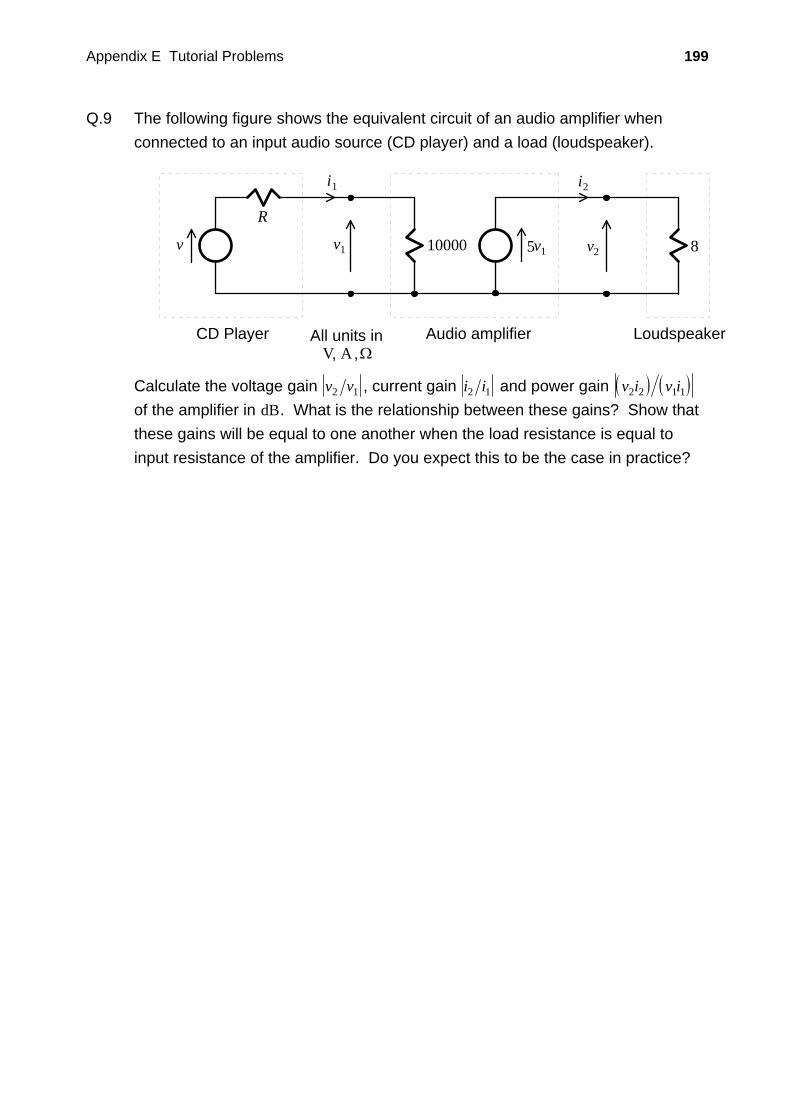
Q.9 The following figure shows the equivalent circuit of an audio amplifier when connected to an input audio source (CD player) and a load (loudspeaker).
Audio amplifier
v1
i1
v210000 5v1 8
Loudspeaker
v
R
i2
CD Player All units inV A Ω, ,
Calculate the voltage gain v v2 1 , current gain i i2 1 and power gain ( ) ( )v i v i2 2 1 1 of the amplifier in dB. What is the relationship between these gains? Show that these gains will be equal to one another when the load resistance is equal to input resistance of the amplifier. Do you expect this to be the case in practice?
Appendix E Tutorial Problems 200
E.2 KCL, KVL and Grounding
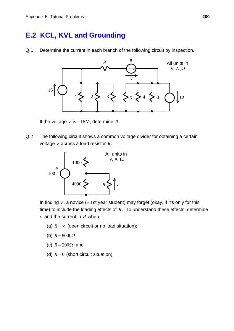
Q.1 Determine the current in each branch of the following circuit by inspection.
164 2 8 4 3
R 8
12
All units inV A Ω, ,
v
6
If the voltage v is −16V , determine R .
Q.2 The following circuit shows a common voltage divider for obtaining a certain
voltage v across a load resistor R .
100
R v
All units inV A Ω, ,1000
4000
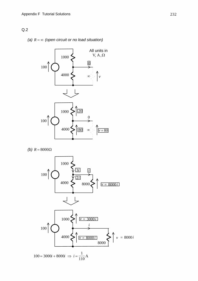
In finding v , a novice (= 1st year student) may forget (okay, if it's only for this time) to include the loading effects of R . To understand these effects, determine v and the current in R when
(a) R = ∞ (open circuit or no load situation);
(b) R = 8000Ω;
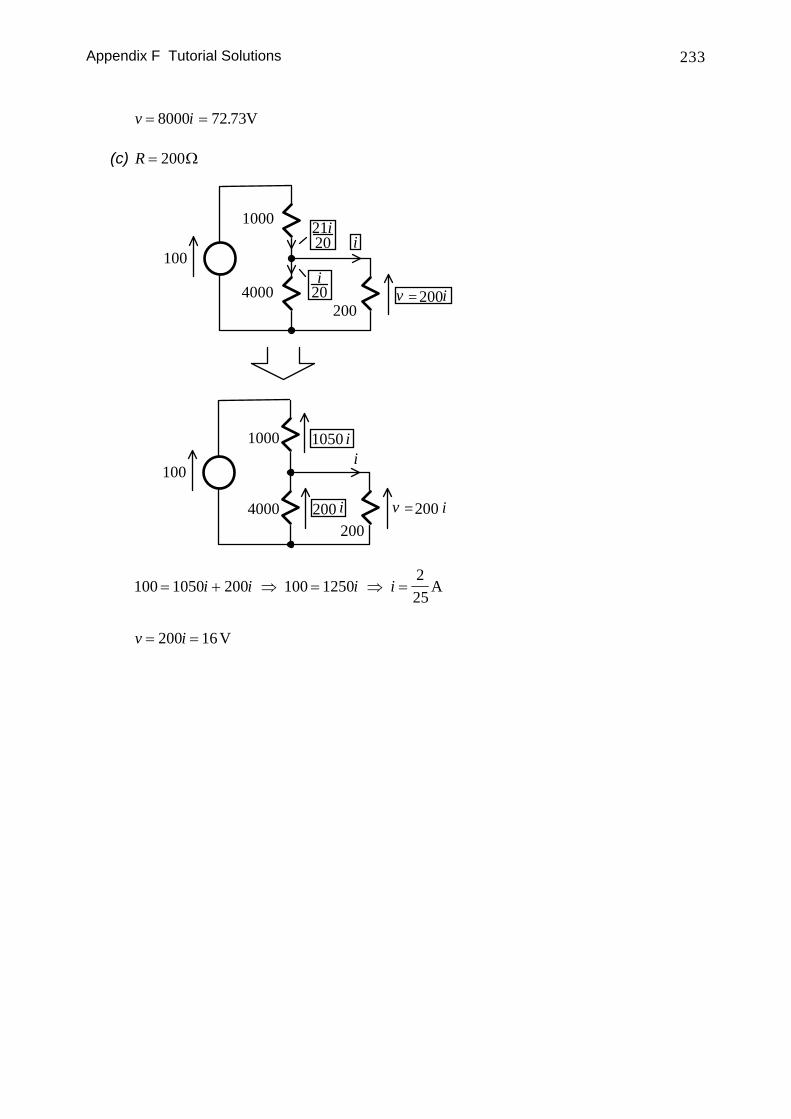
(c) R = 200Ω; and
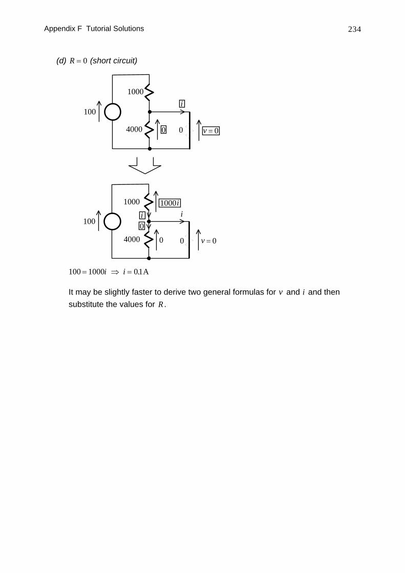
(d) R = 0 (short circuit situation).
Appendix E Tutorial Problems 201
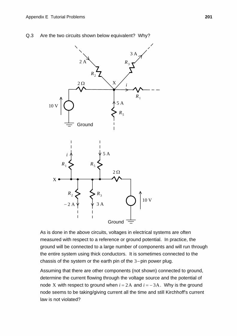
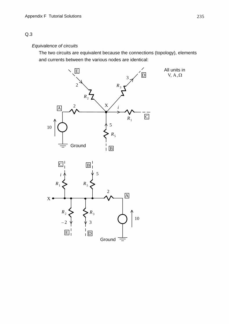
Q.3 Are the two circuits shown below equivalent? Why?
5 A
3 A2 A−
i
10 V
2 Ω
R1 R5
R3R2
Ground
X
X
R2
2 A R3
3 A
R5
5 A10 V
2 Ω
Ground
R1
i
As is done in the above circuits, voltages in electrical systems are often measured with respect to a reference or ground potential. In practice, the ground will be connected to a large number of components and will run through the entire system using thick conductors. It is sometimes connected to the chassis of the system or the earth pin of the 3−pin power plug.
Assuming that there are other components (not shown) connected to ground, determine the current flowing through the voltage source and the potential of node X with respect to ground when i = 2A and i = − 3A . Why is the ground node seems to be taking/giving current all the time and still Kirchhoff's current law is not violated?
Appendix E Tutorial Problems 202
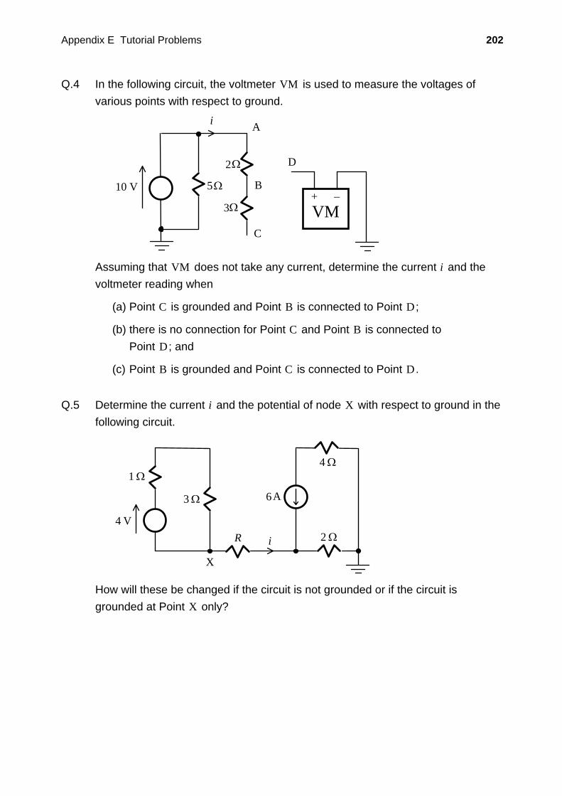
Q.4 In the following circuit, the voltmeter VM is used to measure the voltages of various points with respect to ground.
10 V
2Ω
3Ω
A
B
C
i
+ −VM
D
5Ω
Assuming that VM does not take any current, determine the current i and the voltmeter reading when
(a) Point C is grounded and Point B is connected to Point D ;
(b) there is no connection for Point C and Point B is connected to Point D ; and
(c) Point B is grounded and Point C is connected to Point D .
Q.5 Determine the current i and the potential of node X with respect to ground in the
following circuit.
3 Ω
1 Ω
6
4 VR i 2 Ω
4 Ω
A
X
How will these be changed if the circuit is not grounded or if the circuit is grounded at Point X only?
Appendix E Tutorial Problems 203
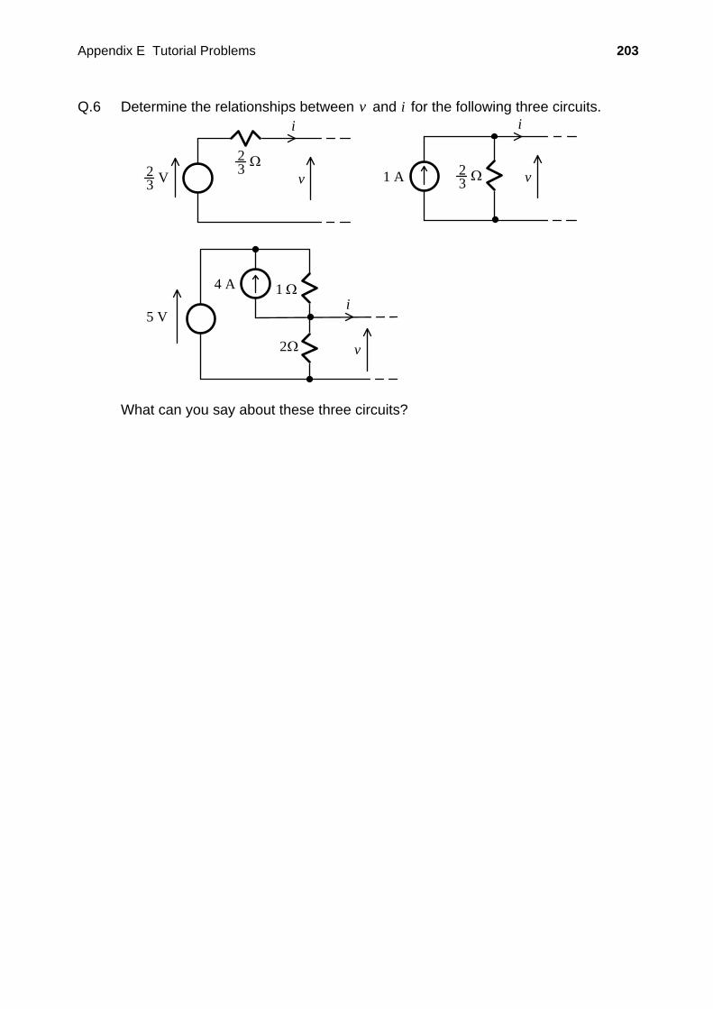
Q.6 Determine the relationships between v and i for the following three circuits. i
v23 V
Ω23
i
v1 A Ω23
5 V
1 Ω
2Ω
i
v
4 A
What can you say about these three circuits?
Appendix E Tutorial Problems 204
E.3 DC Circuit Analysis I
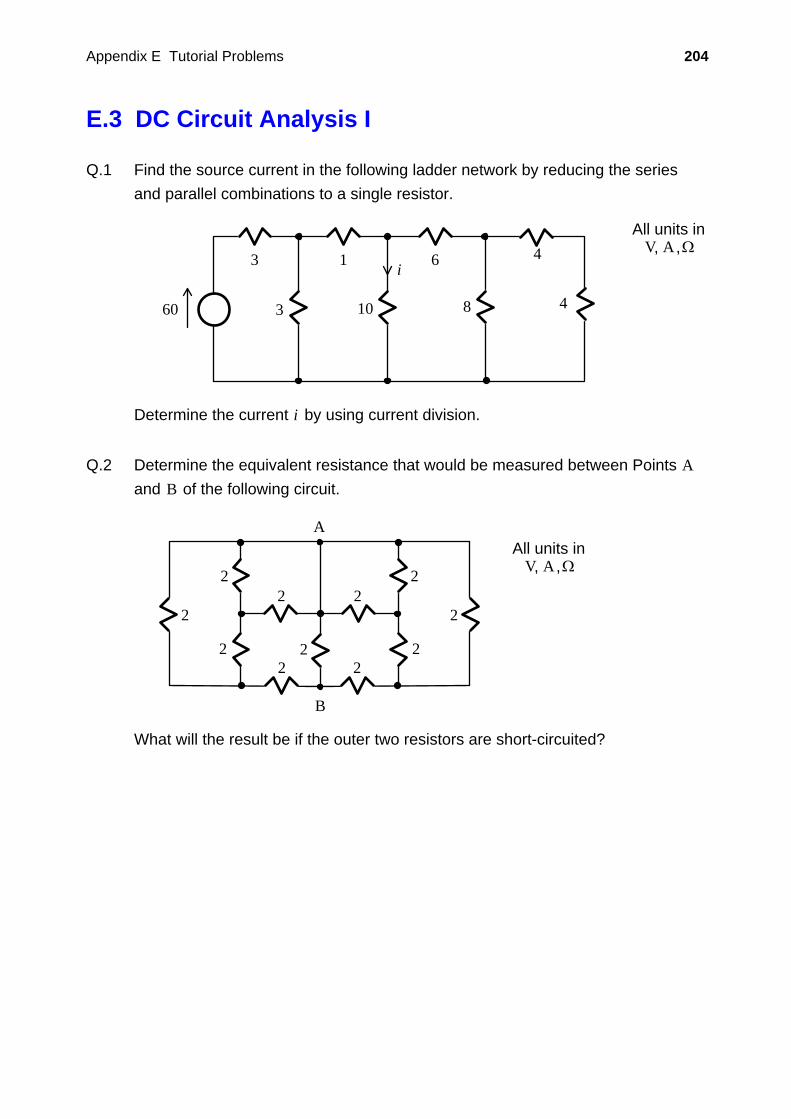
Q.1 Find the source current in the following ladder network by reducing the series and parallel combinations to a single resistor.
60 3
All units inV A Ω, ,
3 1
10
6
8
i4
4
Determine the current i by using current division.
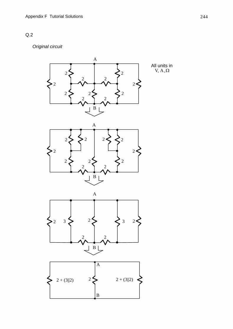
Q.2 Determine the equivalent resistance that would be measured between Points A
and B of the following circuit.
2
All units inV A Ω, ,
2
2
2
22
2
2
2
2
2
A
B
What will the result be if the outer two resistors are short-circuited?
Appendix E Tutorial Problems 205
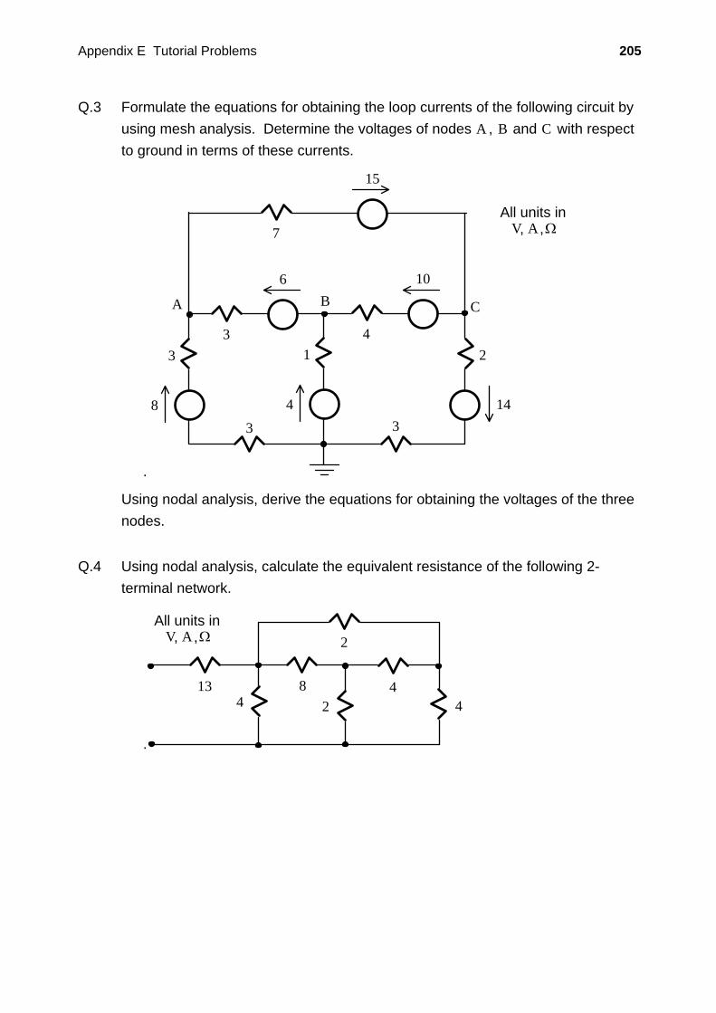
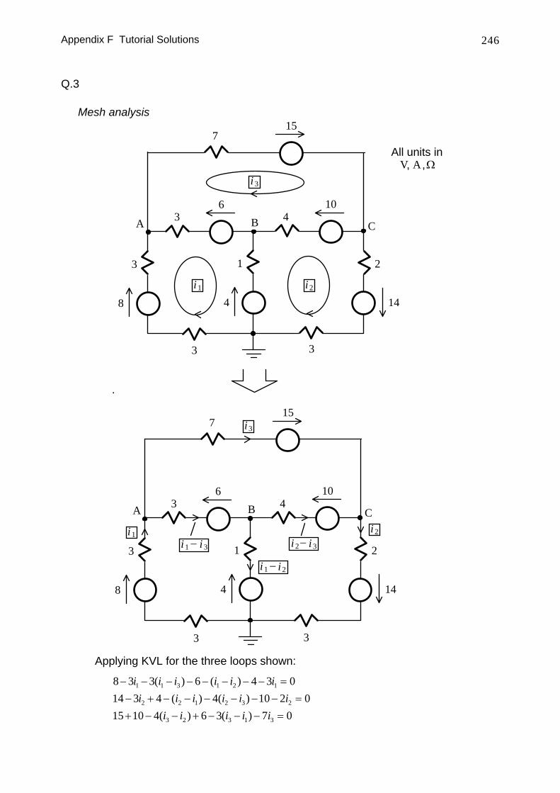
Q.3 Formulate the equations for obtaining the loop currents of the following circuit by using mesh analysis. Determine the voltages of nodes A , B and C with respect to ground in terms of these currents.
.
8
3
All units inV A Ω, ,
3
6
4
14
10
14
2
7
15
A B C
33
Using nodal analysis, derive the equations for obtaining the voltages of the three nodes.
Q.4 Using nodal analysis, calculate the equivalent resistance of the following 2-
terminal network.
.
All units inV A Ω, ,
44
2
82
134
Appendix E Tutorial Problems 206
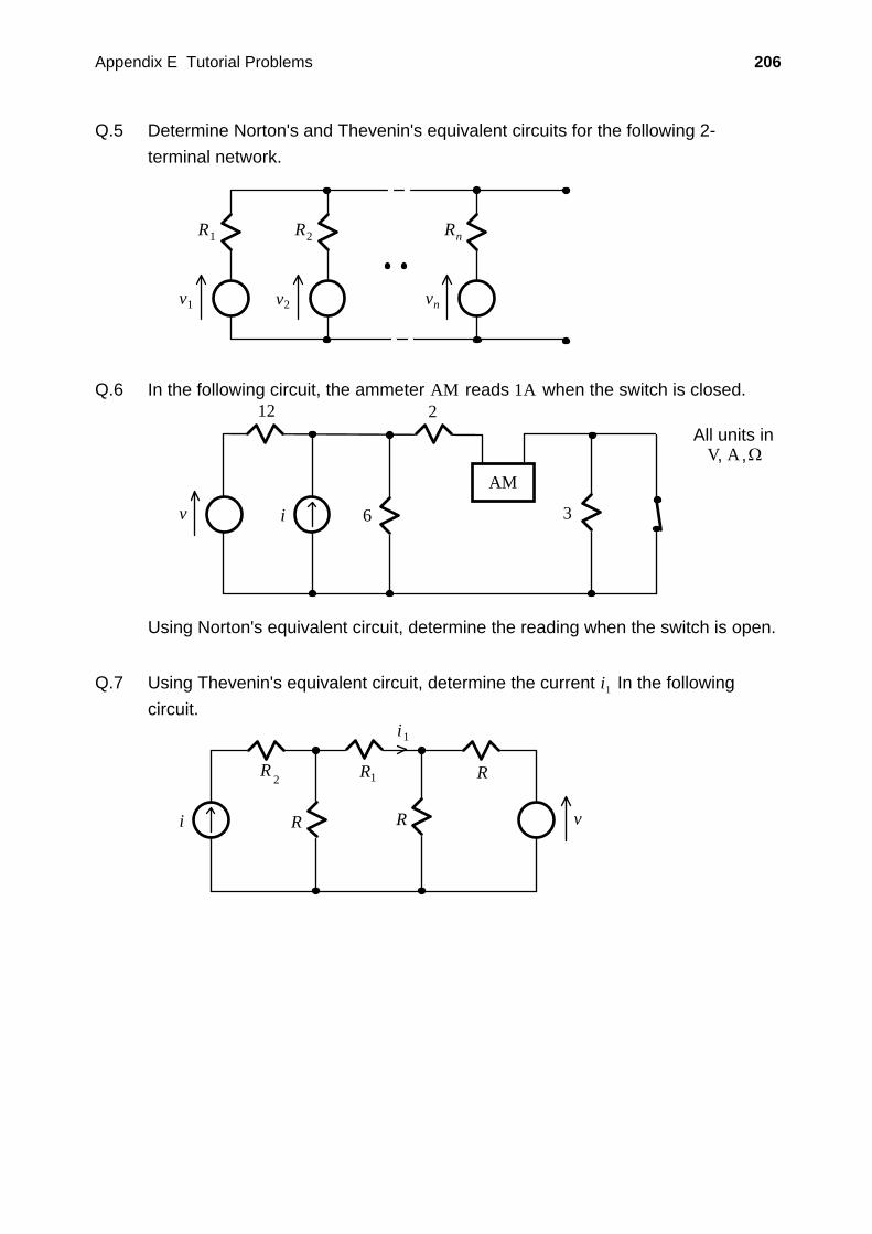
Q.5 Determine Norton's and Thevenin's equivalent circuits for the following 2-terminal network.
R1
v1
R2
v2
Rn
vn
Q.6 In the following circuit, the ammeter AM reads 1A when the switch is closed.
12
6 3
All units inV A Ω, ,
v i
2
AM
Using Norton's equivalent circuit, determine the reading when the switch is open.
Q.7 Using Thevenin's equivalent circuit, determine the current i1 In the following
circuit.
i R vR
R R
1i
1R 2
Appendix E Tutorial Problems 207
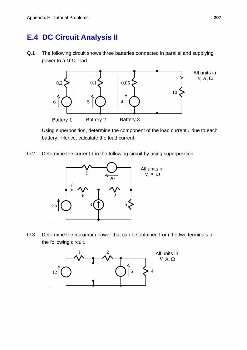
E.4 DC Circuit Analysis II
Q.1 The following circuit shows three batteries connected in parallel and supplying power to a 10Ω load.
6
0.2
Battery 1
5
0.1
Battery 2
4
0.05
Battery 3
10
All units inV A Ω, ,i
Using superposition, determine the component of the load current i due to each battery. Hence, calculate the load current.
Q.2 Determine the current i in the following circuit by using superposition.
.
All units inV A Ω, ,
5
6 2
5
i
25 3
20
Q.3 Determine the maximum power that can be obtained from the two terminals of
the following circuit.
.
6
1 2
12 4
All units inV A Ω, ,
Appendix E Tutorial Problems 208
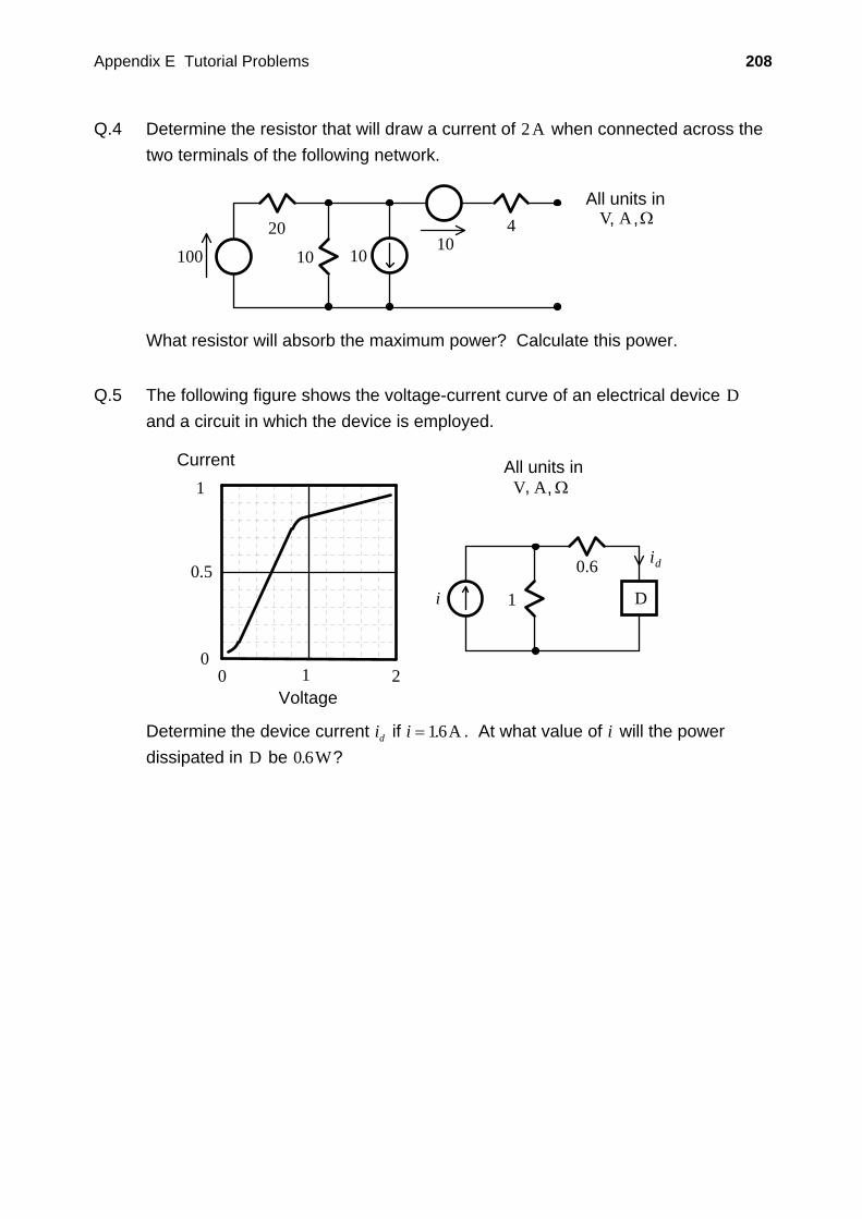
Q.4 Determine the resistor that will draw a current of 2A when connected across the two terminals of the following network.
All units inV A Ω, ,420
10100 1010
What resistor will absorb the maximum power? Calculate this power.
Q.5 The following figure shows the voltage-current curve of an electrical device D
and a circuit in which the device is employed.
i
id
1
0.6
D
1
0.5
00 1 2
Voltage
Current All units inV A Ω, ,
Determine the device current id if i = 16. A . At what value of i will the power dissipated in D be 0 6. W?
Appendix E Tutorial Problems 209
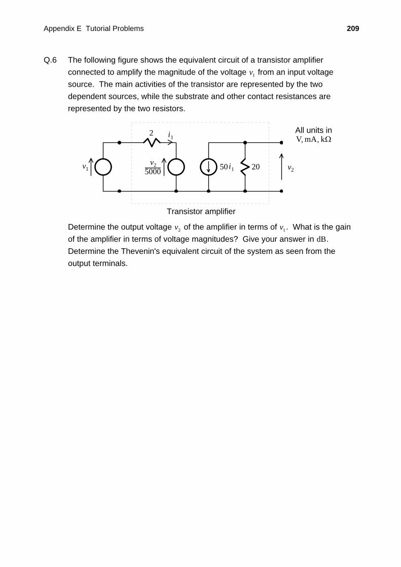
Q.6 The following figure shows the equivalent circuit of a transistor amplifier connected to amplify the magnitude of the voltage v1 from an input voltage source. The main activities of the transistor are represented by the two dependent sources, while the substrate and other contact resistances are represented by the two resistors.
Transistor amplifier
v1
i1
20 v2
2
50 i1
All units inV mA Ω, , k
v25000
Determine the output voltage v2 of the amplifier in terms of v1. What is the gain of the amplifier in terms of voltage magnitudes? Give your answer in dB. Determine the Thevenin's equivalent circuit of the system as seen from the output terminals.
Appendix E Tutorial Problems 210
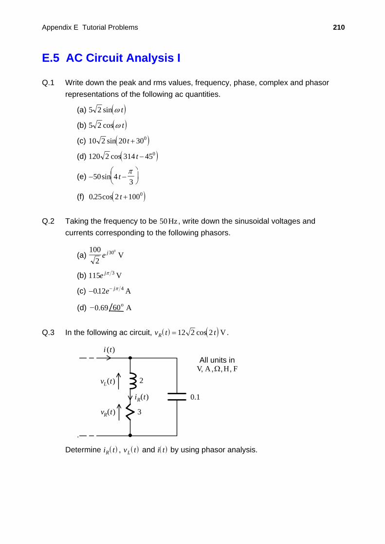
E.5 AC Circuit Analysis I
Q.1 Write down the peak and rms values, frequency, phase, complex and phasor representations of the following ac quantities.
(a) ( )5 2 sin ω t
(b) ( )5 2 cos ω t
(c) ( )10 2 20 300sin t +
(d) ( )120 2 314 450cos t −
(e) − −⎛⎝⎜
⎞⎠⎟50 4
3sin t
π
(f) ( )0 25 2 1000. cos t +
Q.2 Taking the frequency to be 50Hz , write down the sinusoidal voltages and
currents corresponding to the following phasors.
(a) 100
2300
e j V
(b) 115 3e jπ V
(c) − −012 4. e jπ A
60o0.69−(d) A Q.3 In the following ac circuit, ( ) ( )v t tR = 12 2 2cos V .
.
2
3
0.1
i (t)
Lv (t)
Ri (t)
Rv (t)
All units inV A Ω, , ,H F,
Determine ( )i tR , ( )v tL and ( )i t by using phasor analysis.
Appendix E Tutorial Problems 211
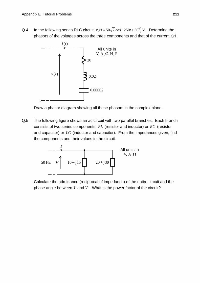
Q.4 In the following series RLC circuit, ( ) ( )v t t= +50 2 1250 300cos V . Determine the phasors of the voltages across the three components and that of the current ( )i t .
.
i (t)
v (t)
20
0.02
0.00002
All units inV A Ω, , ,H F,
Draw a phasor diagram showing all these phasors in the complex plane.
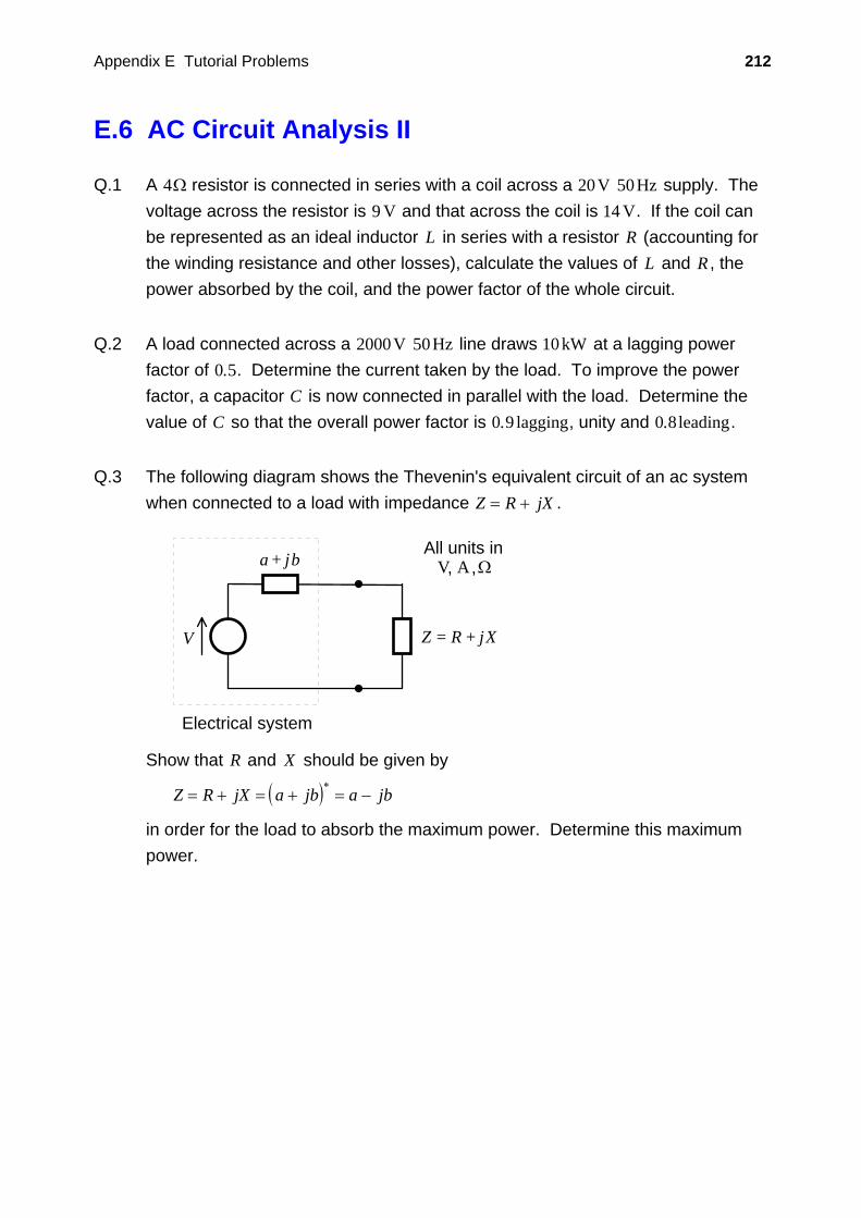
Q.5 The following figure shows an ac circuit with two parallel branches. Each branch
consists of two series components: RL (resistor and inductor) or RC (resistor and capacitor) or LC (inductor and capacitor). From the impedances given, find the components and their values in the circuit.
V
All units inV A Ω, ,
j10 15
I
j20− 3050 Hz +
Calculate the admittance (reciprocal of impedance) of the entire circuit and the phase angle between I and V . What is the power factor of the circuit?
Appendix E Tutorial Problems 212
E.6 AC Circuit Analysis II
Q.1 A 4Ω resistor is connected in series with a coil across a 20V 50Hz supply. The voltage across the resistor is 9 V and that across the coil is 14 V. If the coil can be represented as an ideal inductor L in series with a resistor R (accounting for the winding resistance and other losses), calculate the values of L and R , the power absorbed by the coil, and the power factor of the whole circuit.
Q.2 A load connected across a 2000V 50Hz line draws 10 kW at a lagging power
factor of 0 5. . Determine the current taken by the load. To improve the power factor, a capacitor C is now connected in parallel with the load. Determine the value of C so that the overall power factor is 0 9. lagging, unity and 0 8. leading.
Q.3 The following diagram shows the Thevenin's equivalent circuit of an ac system
when connected to a load with impedance Z R jX= + .
Electrical system
j+
V R= jZ + X
All units inV A Ω, ,a b
Show that R and X should be given by
( )Z R jX a jb a jb= + = + = −∗
in order for the load to absorb the maximum power. Determine this maximum power.
Appendix E Tutorial Problems 213
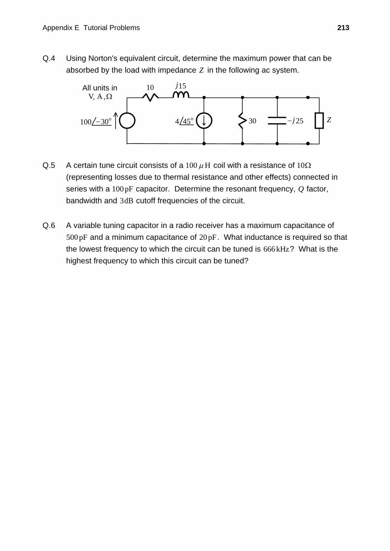
Q.4 Using Norton's equivalent circuit, determine the maximum power that can be absorbed by the load with impedance Z in the following ac system.
10 j15
30 j25−
All units inV A Ω, ,
Z45o4100 30o−
Q.5 A certain tune circuit consists of a 100 μH coil with a resistance of 10Ω
(representing losses due to thermal resistance and other effects) connected in series with a 100pF capacitor. Determine the resonant frequency, Q factor, bandwidth and 3dB cutoff frequencies of the circuit.
Q.6 A variable tuning capacitor in a radio receiver has a maximum capacitance of
500pF and a minimum capacitance of 20pF . What inductance is required so that the lowest frequency to which the circuit can be tuned is 666 kHz? What is the highest frequency to which this circuit can be tuned?
223
F
TUTORIAL SOLUTIONS
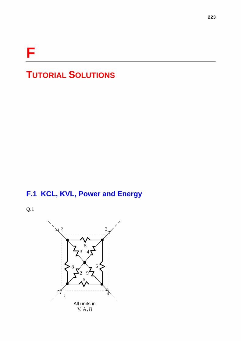
F.1 KCL, KVL, Power and Energy
Q.1
2 3
2
i
3 45
68
All units inV A Ω, ,
4
95
Appendix F Tutorial Solutions 224
Applying KCL to the dotted surface:
i i+ = + ⇒ =2 3 4 5
Q.2
NetworkA
NetworkBR i
10
5
v
5All units in
V, A, Ω
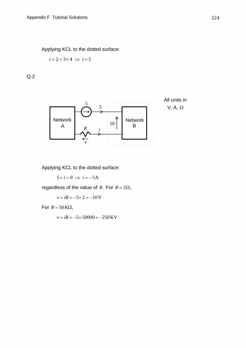
Applying KCL to the dotted surface:
5 0 5+ = ⇒ = −i i A
regardless of the value of R . For R = 2Ω,
v iR= = − × = −5 2 10V
For R = 50KΩ,
v iR= = − × = −5 50000 250KV
Appendix F Tutorial Solutions 225
Q.3
1
3v
4 4
All units inV A Ω, ,
v
4 4 4
v
8
4
1
i
3i
4
2
4
2
4
4
2
4
1
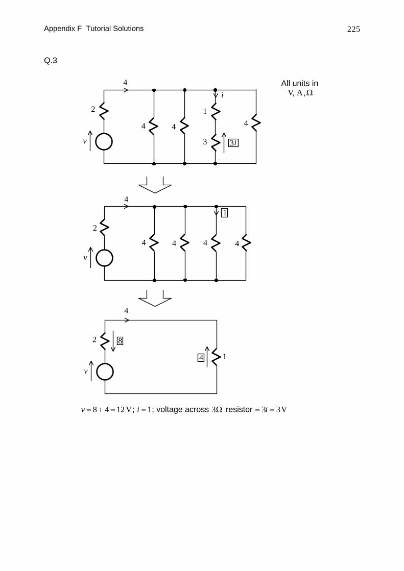
v = + =8 4 12 V; i = 1; voltage across 3Ω resistor = =3 3i V
Appendix F Tutorial Solutions 226
Q.4
(a) Both meters give positive readings
+ −AM
+ −VM
i iv
A B
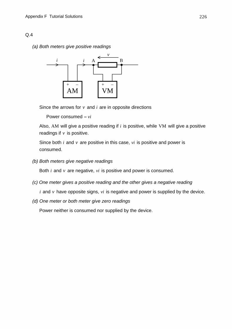
Since the arrows for v and i are in opposite directions
Power consumed = vi
Also, AM will give a positive reading if i is positive, while VM will give a positive readings if v is positive.
Since both i and v are positive in this case, vi is positive and power is consumed.
(b) Both meters give negative readings
Both i and v are negative, vi is positive and power is consumed.
(c) One meter gives a positive reading and the other gives a negative reading
i and v have opposite signs, vi is negative and power is supplied by the device.
(d) One meter or both meter give zero readings
Power neither is consumed nor supplied by the device.
Appendix F Tutorial Solutions 227
Q.5
Current in circuit
5
i All units inV A Ω, ,
i i
4 115
4
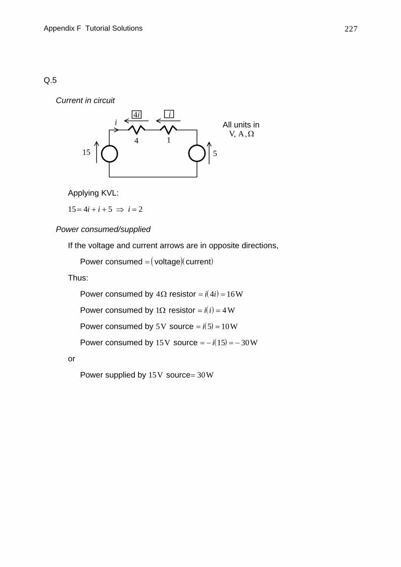
Applying KVL:
15 4 5 2= + + ⇒ =i i i
Power consumed/supplied
If the voltage and current arrows are in opposite directions,
Power consumed ( )( )= voltage current
Thus:
Power consumed by 4Ω resistor ( )= =i i4 16W
Power consumed by 1Ω resistor ( )= =i i 4W
Power consumed by 5V source ( )= =i 5 10W
Power consumed by 15V source ( )= − = −i 15 30W
or
Power supplied by 15V source= 30W
Appendix F Tutorial Solutions 228
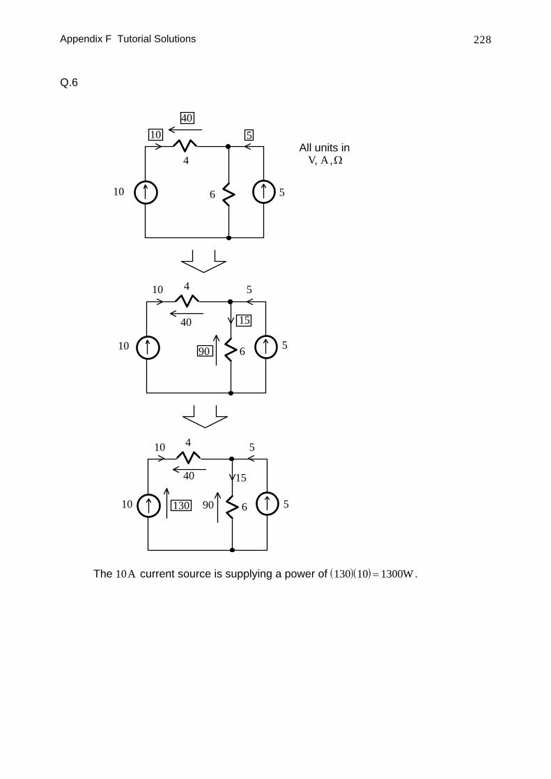
Q.6
All units inV A Ω, ,4
610 5
51040
410
40
5
15
6 510 90
10 4
40
5
56
15
9013010
The 10A current source is supplying a power of ( )( )130 10 1300= W .
Appendix F Tutorial Solutions 229
Q.7
Efficiency
Electrical power supplied ( )( )= =100 20 2000W
Mechanical power delivered ( )( )= =2 5 746 1865. h.p. W h.p. W
Efficiency = =18652000
93 25. %
Torque
Motor speed ( )=⎛
⎝⎜
⎞
⎠⎟ =100
260
206
rev minrad revs min
rad sπ π
Torque = = =Mechanical power delivered
motor speed1865
20 61781
π. Nm
Energy lost
Power lost = − =2000 1865 135W
Energy lost per ( )( )min = =135 60 8100J
Q.8
Generator output power ( )( )= =100 10 1000W
Generator input power = =10000 9
11111.
. W
Generator shaft speed =⎛⎝⎜
⎞⎠⎟⎛
⎝⎜
⎞
⎠⎟ =
110005
260
230 4rev minrad revs min
rad sπ
.
Torque = =11111230 4
4 82.
.. Nm
Appendix F Tutorial Solutions 230
Q.9
Voltage, current and power gains for system
( )
Voltage gain = = =
= = =
gvv
vvv
2
1
1
1
5
5 20 5 14log dB dB
( )
Current gain = = =
= = = =
gii
vv
vv
i2
1
2
1
1
1
810000
5 810000
6250 20 6250 76log dB dB
( )( ) ( )( )[ ]
( ) ( )[ ]
Power gain = = =
= =
= + =+
=
gv iv i
g gp v i2 2
1 1
5 6250 10 5 6250
12
20 5 20 625014 76
245
log
log log
dB
dB dB dB
Relationship between these gains
g g gp v i=
( ) ( ) ( )g
g gp
v idB =dB dB+
2
g g gp v i= = if load resistance equals amplifier's input resistance
Audio amplifier
Most loudspeakers have resistances in the order of a few Ω . However, in order not to load the CD player or other audio input equipment, the input resistance of the amplifier will have to be large and is usually greater than many kΩ.
Appendix F Tutorial Solutions 231
F.2 KCL, KVL and Grounding
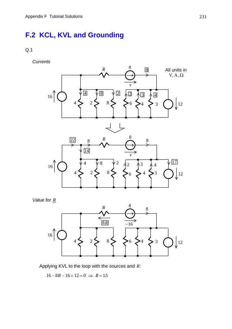
Q.1
Currents
164 2 8 34
R 8
12
All units inV A Ω, ,
v
43284
8
164 2 8 34
R 8
12
v
43284
8
14
822
17
6
2
6
2
Value for R
164 2 8 34
R 8
12
8
168R −
6
Applying KVL to the loop with the sources and R :
16 8 16 12 0 15− − + = ⇒ =R R .
Appendix F Tutorial Solutions 232
Q.2
(a) R = ∞ (open circuit or no load situation)
100
v
All units inV A Ω, ,
0
∞
100
v
0
∞
20
80 = 80
1000
4000
1000
4000
(b) R = 8000Ω
100
100
i
i2
i3
i
v = 8000 i
1000
4000 8000
1000
4000 v = 8000 iv = 8000 i8000
v = 3000 i
100 3000 80001
110= + ⇒ =i i i A
Appendix F Tutorial Solutions 233
v i= =8000 72 73. V
(c) R = 200Ω
100
v
100
i
200 i
i
i20 = 200i
v =200 i
i2021
i
2004000
1000
200
10501000
4000
100 1050 200 100 1250225
= + ⇒ = ⇒ =i i i i A
v i= =200 16V
Appendix F Tutorial Solutions 234
(d) R = 0 (short circuit)
100i
100
v
i
0 = 0
0 v = 00
0
0
i1000i
1000
4000
1000
4000
100 1000 01= ⇒ =i i . A
It may be slightly faster to derive two general formulas for v and i and then substitute the values for R .
Appendix F Tutorial Solutions 235
Q.3
Equivalence of circuits The two circuits are equivalent because the connections (topology), elements
and currents between the various nodes are identical:
5
32−
i
10
2
R1 R5
R3R2
Ground
X
X
R2
2 R3
3
R5
510
2
Ground
R1
iA
A
B
B
C
C
D
DE
E All units inV A Ω, ,
Appendix F Tutorial Solutions 236
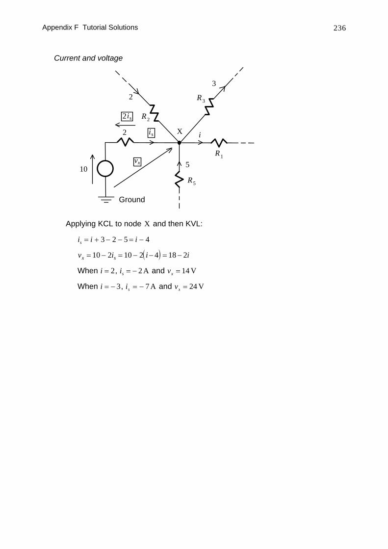
Current and voltage
X
R2
2 R3
3
R5
510
2
Ground
R1
iis
vx
is2
Applying KCL to node X and then KVL:
i i is = + − − = −3 2 5 4
( )v i i ix s= − = − − = −10 2 10 2 4 18 2
When i = 2, is = − 2 A and vx = 14 V
When i = − 3, is = − 7 A and vx = 24 V
Appendix F Tutorial Solutions 237
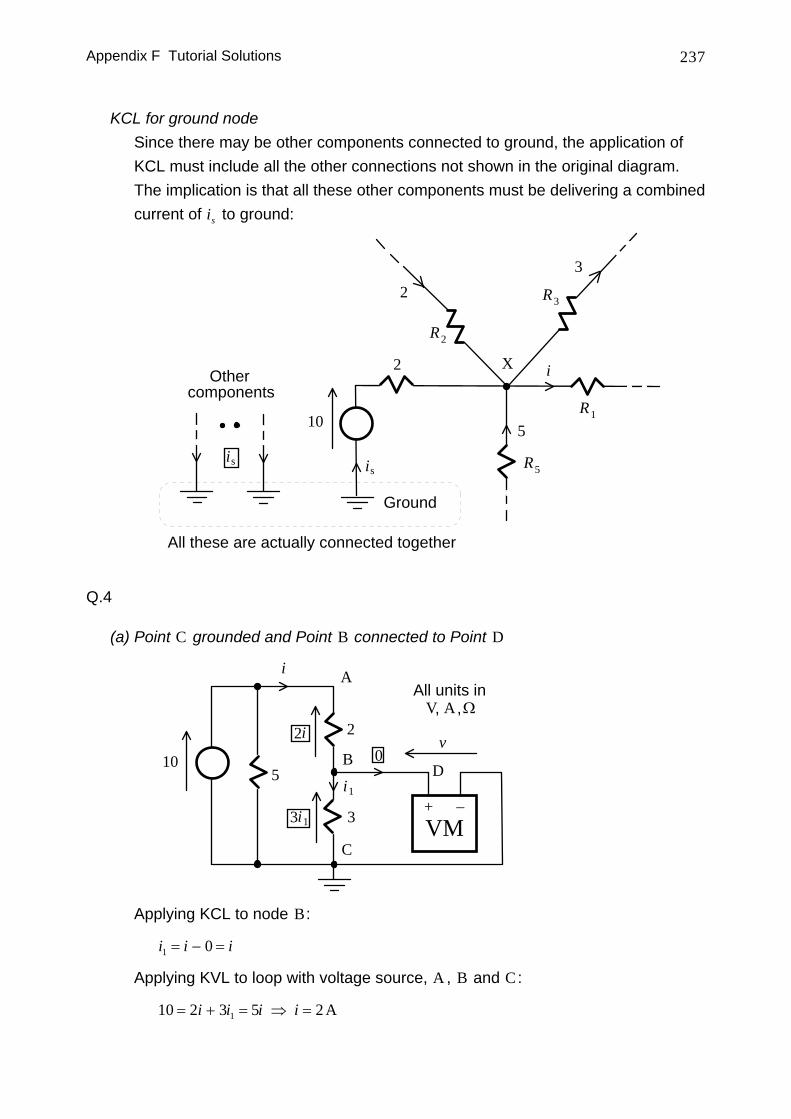
KCL for ground node Since there may be other components connected to ground, the application of
KCL must include all the other connections not shown in the original diagram. The implication is that all these other components must be delivering a combined current of is to ground:
X
R2
2 R3
3
R5
510
2
Ground
R1
i
is
Othercomponents
is
All these are actually connected together
Q.4
(a) Point C grounded and Point B connected to Point D
10
2
3
A
B
C
i
+ −VM
D
v
i1
0
3i1
2i
All units inV A Ω, ,
5
Applying KCL to node B:
i i i1 0= − =
Applying KVL to loop with voltage source, A , B and C :
10 2 3 5 21= + = ⇒ =i i i i A
Appendix F Tutorial Solutions 238
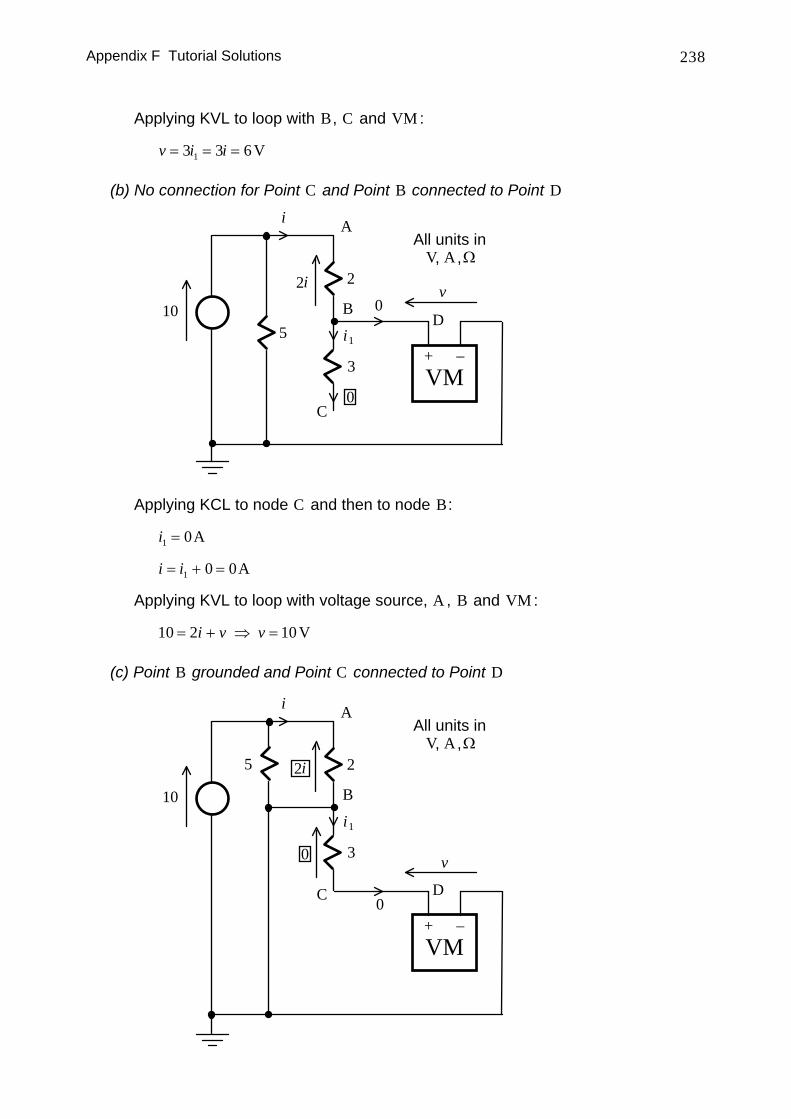
Applying KVL to loop with B, C and VM :
v i i= = =3 3 61 V
(b) No connection for Point C and Point B connected to Point D
10
2
3
A
B
C
i
+ −VM
D
v
i1
02i
All units inV A Ω, ,
0
5
Applying KCL to node C and then to node B:
i1 0= A
i i= + =1 0 0A
Applying KVL to loop with voltage source, A , B and VM :
10 2 10= + ⇒ =i v v V
(c) Point B grounded and Point C connected to Point D
10
2
3
A
B
C
i
i1
2i
All units inV A Ω, ,
v
+ −VM
D
0
0
5
Appendix F Tutorial Solutions 239
Applying KVL to loop with voltage source, A and B:
10 2 5= ⇒ =i i A
Applying KVL to loop with B, C , D and VM :
v i v+ = ⇒ =3 0 01 V
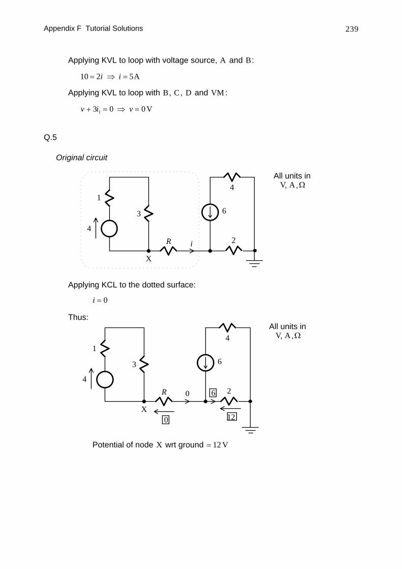
Q.5
Original circuit
3
16
4R i 2
4
X
All units inV A Ω, ,
Applying KCL to the dotted surface:
i = 0
Thus:
3
16
4R 2
4
X
All units inV A Ω, ,
0
0
6
12
Potential of node X wrt ground = 12 V
Appendix F Tutorial Solutions 240
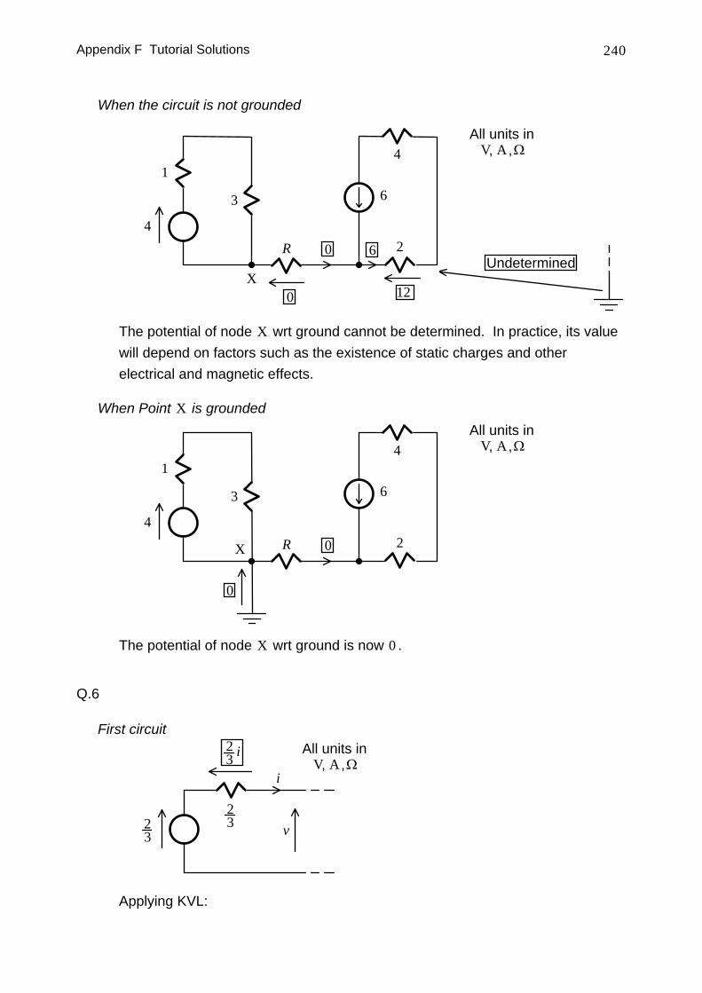
When the circuit is not grounded
3
16
4R 2
4
X
All units inV A Ω, ,
0
6
12
0Undetermined
The potential of node X wrt ground cannot be determined. In practice, its value will depend on factors such as the existence of static charges and other electrical and magnetic effects.
When Point X is grounded
3
16
4R 2
4
X
All units inV A Ω, ,
0
0
The potential of node X wrt ground is now 0 .
Q.6
First circuit
i
v23
23
23 i All units in
V A Ω, ,
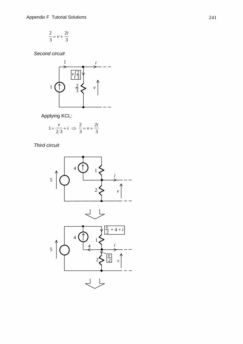
Applying KVL:
Appendix F Tutorial Solutions 241
23
23
= +vi
Second circuit
i
v23
v 23
1
1
Applying KCL:
12 3
23
23
= + ⇒ = +v
i vi
Third circuit
5
1
2
i
v
4
5
1
2
i
v
4
4
v2
v2 + 4 + i
Appendix F Tutorial Solutions 242
5
1
2i
v
44
v2 + 4 + i
From KVL:
5 2 4 32 4= + + + = + +v i v v i
132
23
23
= + ⇒ = +v
i vi
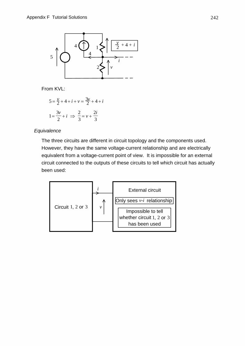
Equivalence
The three circuits are different in circuit topology and the components used. However, they have the same voltage-current relationship and are electrically equivalent from a voltage-current point of view. It is impossible for an external circuit connected to the outputs of these circuits to tell which circuit has actually been used:
i
v
External circuit
Impossible to tellwhether circuit 1, 2 or 3
has been used
Only sees v-i relationshipCircuit 1, 2 or 3
Appendix F Tutorial Solutions 243
F.3 DC Circuit Analysis I
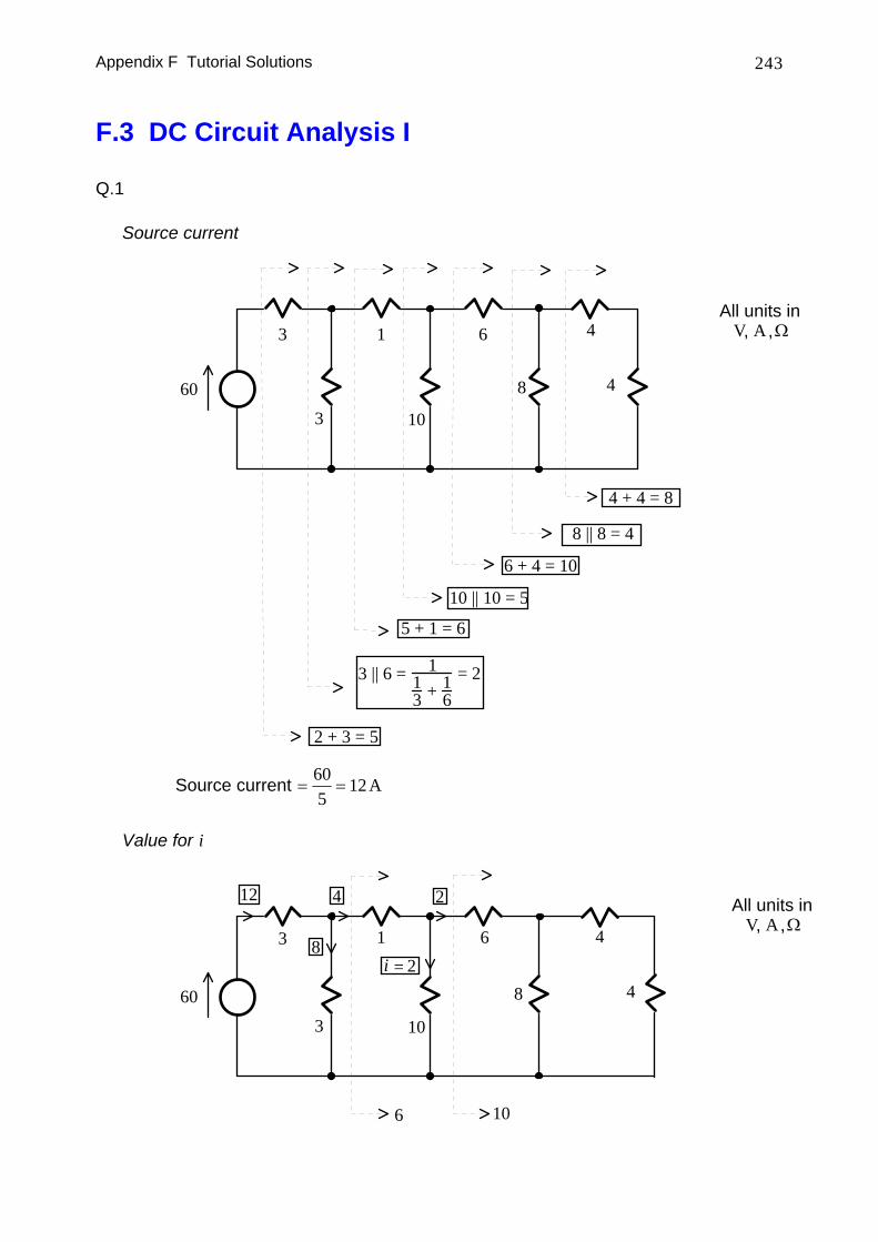
Q.1
Source current
60
3
All units inV A Ω, ,3 1
10
6
8
6 + 4 = 10
10 || 10 = 5
5 + 1 = 6
3 || 6 = 113 + 1
6= 2
2 + 3 = 5
4
4
4 + 4 = 8
8 || 8 = 4
Source current = =605
12 A
Value for i
60
3
All units inV A Ω, ,
3 1
10
6
8
106
12
8
4 2
2=i4
4
Appendix F Tutorial Solutions 244
Q.2
Original circuit
2All units in
V A Ω, ,
2
2
2
22
2
2
2
2
2
A
B
2
2
22
2
2
2
22
A
B
2 2
2 3
2
2 2
2
A
B
3
2
A
B
2 + (3||2)2 + (3||2)
Appendix F Tutorial Solutions 245
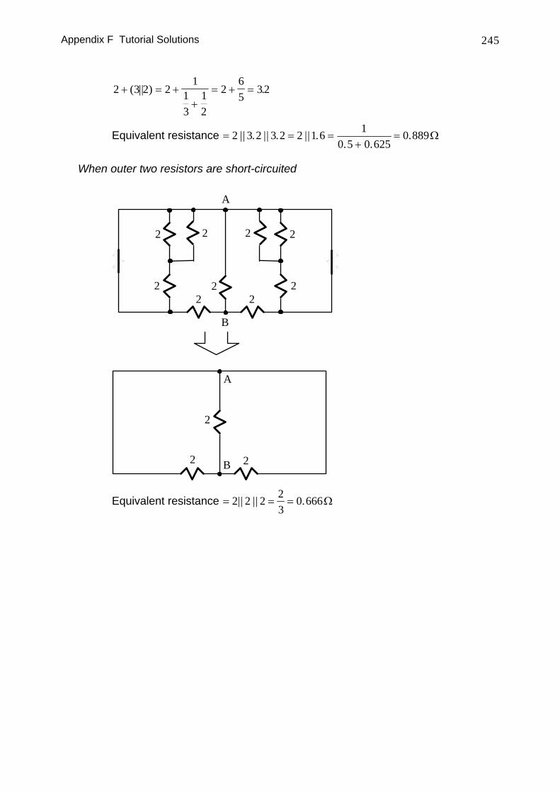
2 3 2 21
13
12
265
32+ = ++
= + =( || ) .
Equivalent resistance = = =+
=2 3 2 3 2 2 1 6 10 5 0 625
0 889|| . || . || .. .
. Ω
When outer two resistors are short-circuited
2
22
2
2
22
A
B
2 2
2
2
A
B2
Equivalent resistance = = =2 2 2 23
0 666|| || . Ω
Appendix F Tutorial Solutions 246
Q.3
Mesh analysis
.
8
3
All units inV A Ω, ,
36
4
1
410
14
2
715
A B C
i1 i2
i3
3 3
8
3
36
4
1
410
14
2
715
A B Ci2
i3
i1 i 3−i1
−i 2
i1 − i2
i3
3 3
Applying KVL for the three loops shown:
07)(36)(41015
0210)(4)(4314034)(6)(338
31323
232122
121311
=−−−+−−+=−−−−−−+−
=−−−−−−−−
iiiiiiiiiii
iiiiii
Appendix F Tutorial Solutions 247
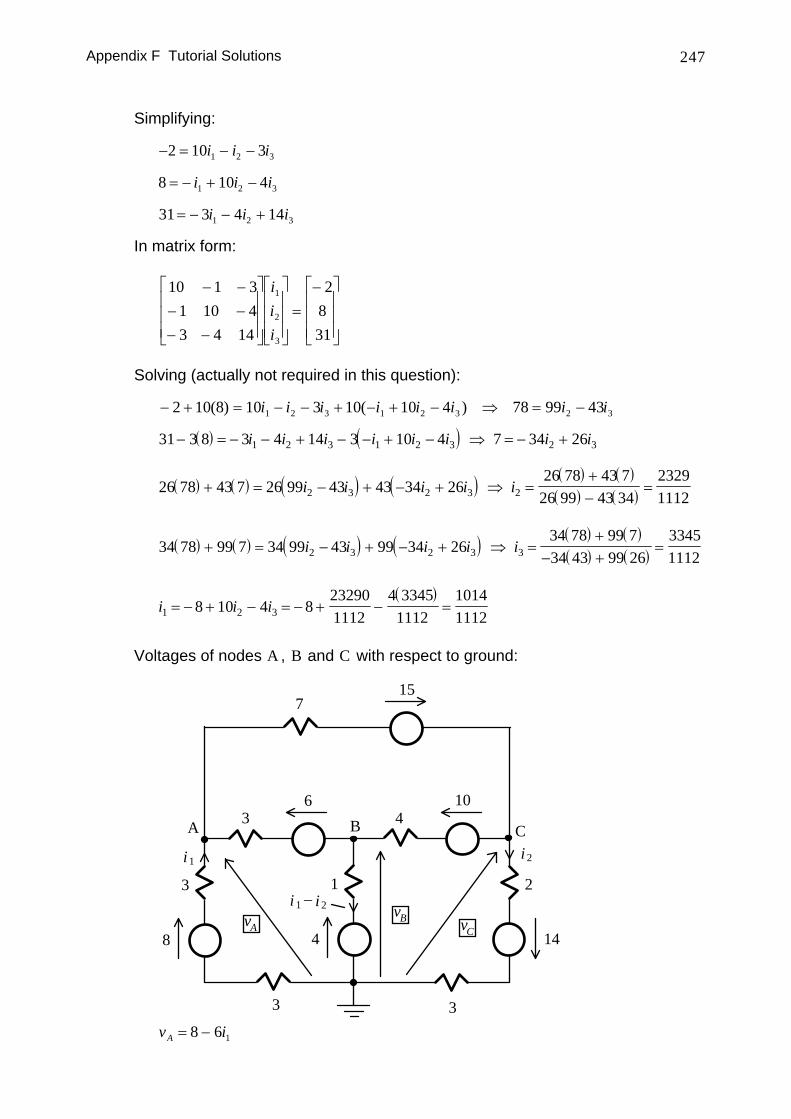
Simplifying:
− = − −2 10 31 2 3i i i
8 10 41 2 3= − + −i i i
31 3 4 141 2 3= − − +i i i
In matrix form:
10 1 3
1 10 43 4 14
2831
1
2
3
− −− −− −
⎡
⎣
⎢⎢⎢
⎤
⎦
⎥⎥⎥
⎡
⎣
⎢⎢⎢
⎤
⎦
⎥⎥⎥=
−⎡
⎣
⎢⎢⎢
⎤
⎦
⎥⎥⎥
iii
Solving (actually not required in this question):
− + = − − + − + − ⇒ = −2 10 8 10 3 10 10 4 78 99 431 2 3 1 2 3 2 3( ) ( )i i i i i i i i
( ) ( )31 3 8 3 4 14 3 10 4 7 34 261 2 3 1 2 3 2 3− = − − + − − + − ⇒ = − +i i i i i i i i
( ) ( ) ( ) ( ) ( ) ( )( ) ( )26 78 43 7 26 99 43 43 34 26
26 78 43 726 99 43 34
232911122 3 2 3 2+ = − + − + ⇒ =
+−
=i i i i i
( ) ( ) ( ) ( ) ( ) ( )( ) ( )34 78 99 7 34 99 43 99 34 26
34 78 99 734 43 99 26
334511122 3 2 3 3+ = − + − + ⇒ =
+− +
=i i i i i
( )
i i i1 2 38 10 4 8232901112
4 33451112
10141112
= − + − = − + − =
Voltages of nodes A , B and C with respect to ground:
8
3
36
4
1
410
14
2
715
A B Ci 2i1
i 1 − i2
vC
vBvA
3 3 v iA = −8 6 1
Appendix F Tutorial Solutions 248
v i iB = + −4 1 2
v iC = − +14 5 2
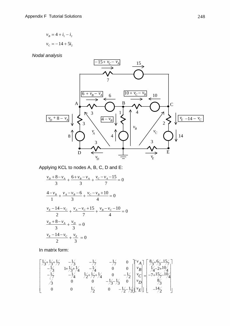
Nodal analysis
8
3
3
6
4
1 4
10
14
2
7
15
A B C
vC
vBvA
8 − vA
6 − vA+ vB
15 − vA+ vC−
14 − vC−4 − vB
10 −+ vBvC
3 3
D EvD vE
vD + vE
Applying KCL to nodes A, B, C, D and E:
v v v v v vD A B A C A+ −+
+ −+
− −=
83
63
157
0
41
63
104
0−+
− −+
− +=
v v v v vB A B C B
v v v v v vE C A C B C− −+
− ++
− −=
142
157
104
0
v v vD A D+ −+ =
83 3
0
v v vE C E− −+ =
142 3
0
In matrix form:
13 13 1713
17
3
13 17 17 01 1
314
14 0 0
14
12
17
14 0 1
20 0 1
313 0
0 0 12 0 12 13
83 63 15714 2 10
47 15
710
48
3142
+ +−−
− − −+ + −− + + −
− −
− −
=
+ −− +
− + −
−
⎡
⎣
⎢⎢⎢⎢⎢⎢
⎤
⎦
⎥⎥⎥⎥⎥⎥
⎡
⎣
⎢⎢⎢⎢⎢⎢
⎤
⎦
⎥⎥⎥⎥⎥⎥
⎡
⎣
⎢⎢⎢⎢⎢⎢
⎤
`
vAvBvCvDvE ⎦
⎥⎥⎥⎥⎥⎥
Appendix F Tutorial Solutions 249
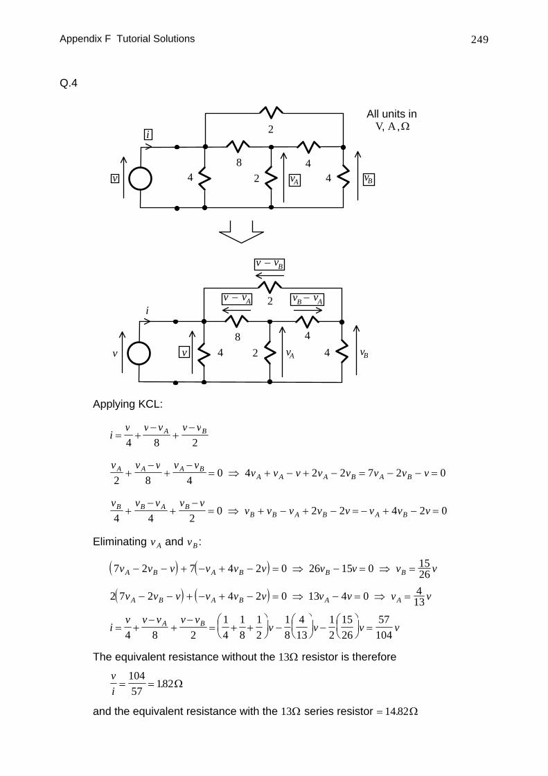
Q.4
All units inV A Ω, ,
44
2
82 vA vBv
i
4
44
2
82 vA vBv
− vAvBi
− vAv
−v vB
4v
Applying KCL:
iv v v v vA B= +
−+
−4 8 2
v v v v v
v v v v v v v vA A A BA A A B A B2 8 4
0 4 2 2 7 2 0+−
+−
= ⇒ + − + − = − − =
v v v v v
v v v v v v v vB B A BB B A B A B4 4 2
0 2 2 4 2 0+−
+−
= ⇒ + − + − = − + − =
Eliminating v A and vB :
( ) ( )7 2 7 4 2 0 26 15 0 1526v v v v v v v v v vA B A B B B− − + − + − = ⇒ − = ⇒ =
( ) ( )2 7 2 4 2 0 13 4 0 413v v v v v v v v v vA B A B A A− − + − + − = ⇒ − = ⇒ =
iv v v v v
v v v vA B= +−
+−
= + +⎛⎝⎜
⎞⎠⎟ −
⎛⎝⎜
⎞⎠⎟ −
⎛⎝⎜
⎞⎠⎟ =
4 8 214
18
12
18
413
12
1526
57104
The equivalent resistance without the 13Ω resistor is therefore
vi= =
10457
182. Ω
and the equivalent resistance with the 13Ω series resistor = 14 82. Ω
Appendix F Tutorial Solutions 250
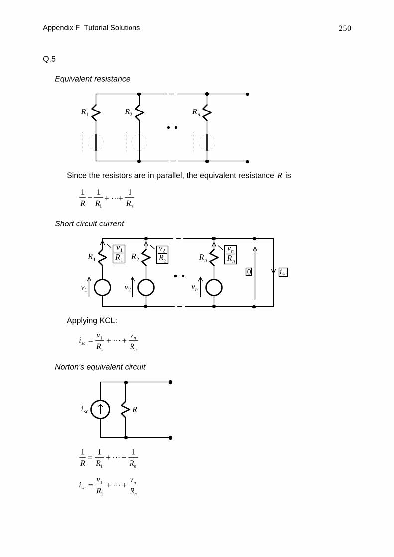
Q.5
Equivalent resistance
R1 R2 Rn
Since the resistors are in parallel, the equivalent resistance R is
1 1 1
1R R Rn= + +
Short circuit current
R1 R2 Rn
isc0
RnR2R1
v1 v2 vn
v1 v2 vn
Applying KCL:
ivR
vRsc
n
n
= + +1
1
Norton's equivalent circuit
i sc R
1 1 1
1R R Rn
= + +
ivR
vRsc
n
n
= + +1
1
Appendix F Tutorial Solutions 251
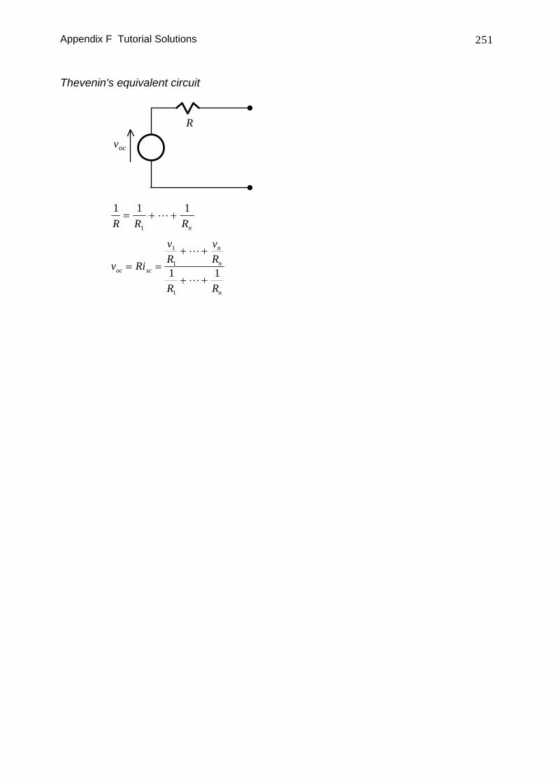
Thevenin's equivalent circuit
voc
R
1 1 1
1R R Rn
= + +
v Ri
vR
vR
R R
oc sc
n
n
n
= =+ +
+ +
1
1
1
1 1
Appendix F Tutorial Solutions 252
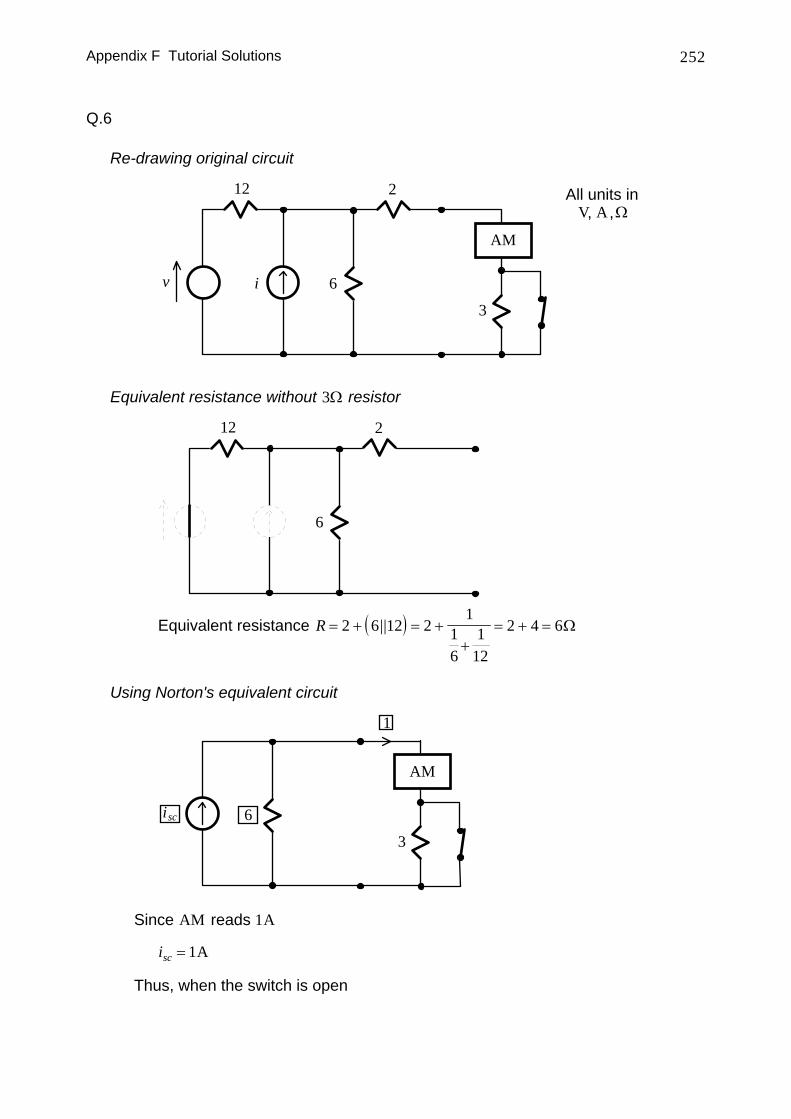
Q.6
Re-drawing original circuit
12
6
All units inV A Ω, ,
v i
2
3
AM
Equivalent resistance without 3Ω resistor
12
6
2
Equivalent resistance ( )R = + = ++
= + =2 6 12 21
16
112
2 4 6|| Ω
Using Norton's equivalent circuit
6
3
AM
isc
1
Since AM reads 1A
isc = 1A
Thus, when the switch is open
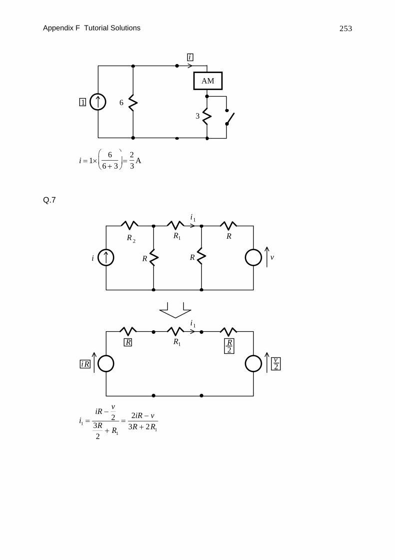
Appendix F Tutorial Solutions 253
6
3
AM
1
i
i = ×+
⎛
⎝⎜
⎞
⎠⎟ =1
66 3
23
A
Q.7
i v
R R
1i
R
R2
2
i R vR
R R
1i
1
1R 2
iiR v
R R
iR vR R1
11
232
23 2
=−
+=
−+
Appendix F Tutorial Solutions 254
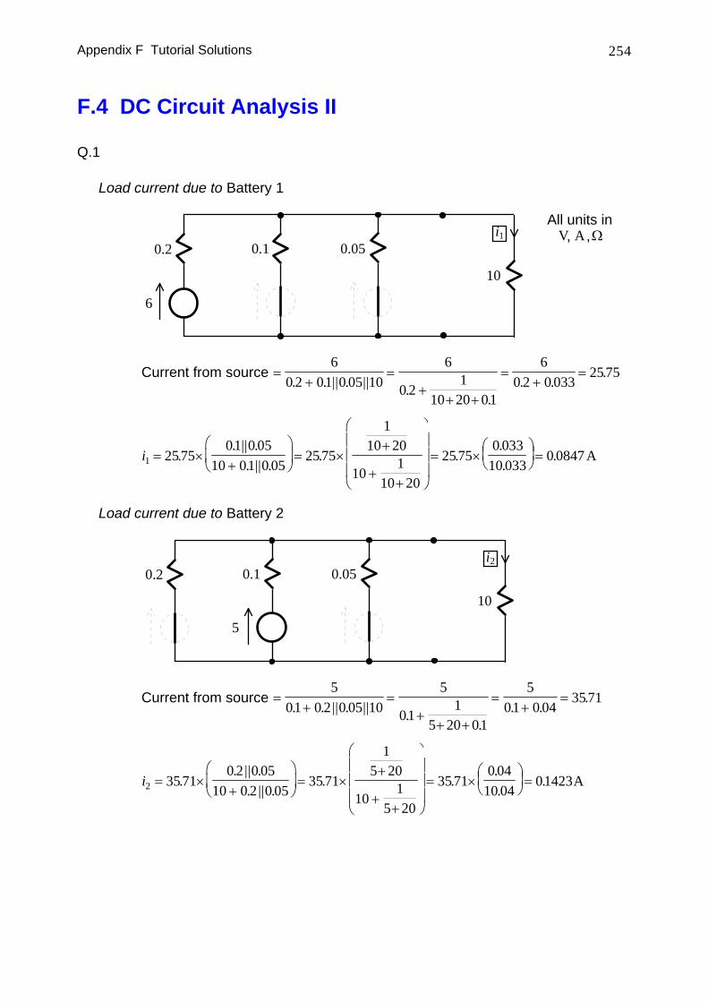
F.4 DC Circuit Analysis II
Q.1
Load current due to Battery 1
6
0.2 0.1 0.05
10
All units inV A Ω, ,i1
Current from source =+
=+
+ +
=+
=6
0 2 01 0 05 106
0 21
10 20 01
60 2 0 033
2575. . || . || .
.. .
.
i1 25 7501 0 05
10 01 0 0525 75
110 20
101
10 20
25 750 033
10 0330 0847= ×
+
⎛
⎝⎜
⎞
⎠⎟ = ×
+
++
⎛
⎝
⎜⎜⎜
⎞
⎠
⎟⎟⎟= ×
⎛⎝⎜
⎞⎠⎟ =.
. || .. || .
. ...
. A
Load current due to Battery 2
5
0.2 0.1 0.05
10
i2
Current from source =+
=+
+ +
=+
=5
01 0 2 0 05 105
011
5 20 01
501 0 04
3571. . || . || .
.. .
.
i2 35 710 2 0 05
10 0 2 0 0535 71
15 20
101
5 20
35 710 04
10 0401423= ×
+
⎛
⎝⎜
⎞
⎠⎟ = ×
+
++
⎛
⎝
⎜⎜⎜
⎞
⎠
⎟⎟⎟= ×
⎛⎝⎜
⎞⎠⎟ =.
. || .. || .
. ...
. A
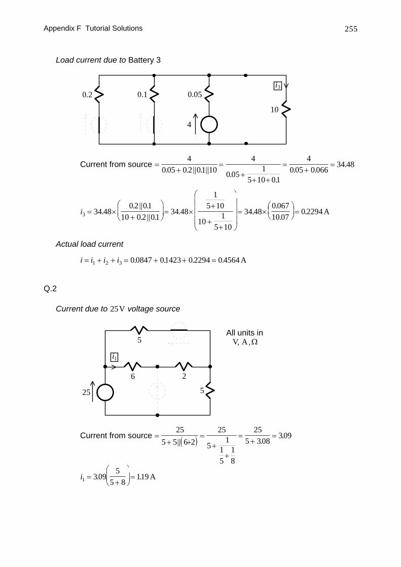
Appendix F Tutorial Solutions 255
Load current due to Battery 3
4
0.2 0.1 0.05
10
i3
Current from source =+
=+
+ +
=+
=4
0 05 0 2 01 104
0 051
5 10 01
40 05 0 066
34 48. . || . || .
.. .
.
i3 34 480 2 01
10 0 2 0134 48
15 10
101
5 10
34 480 06710 07
0 2294= ×+
⎛
⎝⎜
⎞
⎠⎟ = ×
+
++
⎛
⎝
⎜⎜⎜
⎞
⎠
⎟⎟⎟= ×
⎛⎝⎜
⎞⎠⎟ =.
. || .. || .
. ...
. A
Actual load current
i i i i= + + = + + =1 2 3 0 0847 01423 0 2294 0 4564. . . . A
Q.2
Current due to 25V voltage source
All units inV A Ω, ,
5
6 2
5
25
i1
Current from source ( )=+ +
=+
+
=+
=25
5 5 6 225
51
15
18
255 308
309|| .
.
i1 3095
5 8119=
+
⎛
⎝⎜
⎞
⎠⎟ =. . A
Appendix F Tutorial Solutions 256
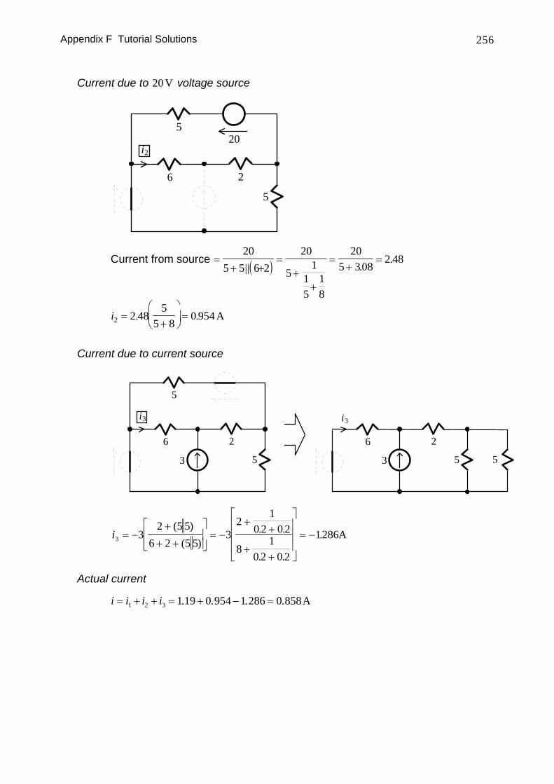
Current due to 20V voltage source
5
6 2
520
i2
Current from source ( )=+ +
=+
+
=+
=20
5 5 6 220
51
15
18
205 308
2 48|| .
.
i2 2 485
5 80 954=
+
⎛
⎝⎜
⎞
⎠⎟ =. . A
Current due to current source
5
6 2
5
3
i3
5
6 2
3
i3
5
i3 32 5 5
6 2 5 53
21
0 2 0 2
81
0 2 0 2
1286= −+
+ +
⎡
⎣⎢⎢
⎤
⎦⎥⎥= −
++
++
⎡
⎣
⎢⎢⎢
⎤
⎦
⎥⎥⎥= −
( )( )
. .
. .
. A
Actual current
i i i i= + + = + − =1 2 3 1 19 0 954 1 286 0 858. . . . A
Appendix F Tutorial Solutions 257
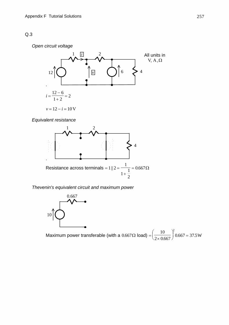
Q.3
Open circuit voltage
.
6
1 2
12 4
All units inV A Ω, ,
i
v
i =−+
=12 61 2
2
v i= − =12 10V
Equivalent resistance
.
1 2
4
Resistance across terminals = =+
=1 21
112
0 667|| . Ω
Thevenin's equivalent circuit and maximum power
0.667
10
Maximum power transferable (with a 0 667. Ω load) =×
⎛⎝⎜
⎞⎠⎟ =
102 0 667
0 667 37 52
.. . W

Appendix F Tutorial Solutions 258
Q.4
All units inV A Ω, ,4
20 10 1010100
20
Combined current of current sources = − =1010020
5
Equivalent parallel resistance = =+
=20 101
120
110
203
||
410
410
5 203
203100
3
703
323
Resistor that draws 2 703 2
323 1A = × − = Ω
Resistor that absorbs the maximum power = 323 Ω
Maximum power that can be transferred =×⎛
⎝⎜
⎞⎠⎟ =
703
32 23
323
122596
2
W
Appendix F Tutorial Solutions 259
Q.5
Thevenin's equivalent circuit
i
id
1
0.6
D
All units inV A Ω, ,
vdi
id1.6
D
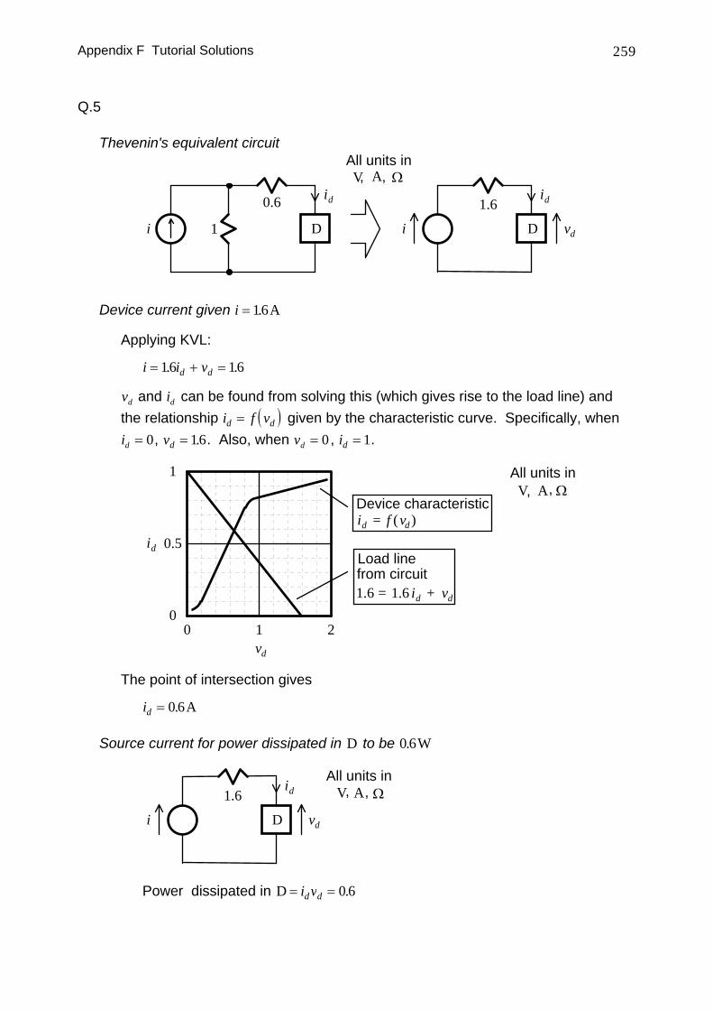
Device current given i = 16. A
Applying KVL:
i i vd d= + =16 16. .
vd and id can be found from solving this (which gives rise to the load line) and the relationship ( )i f vd d= given by the characteristic curve. Specifically, when id = 0, vd = 16. . Also, when vd = 0 , id = 1.
vd
id
1
0.5
00 1 2
All units inV A Ω, ,
id = f (vd )Device characteristic
1.6 = 1.6 id + vd
Load linefrom circuit
The point of intersection gives
id = 0 6. A
Source current for power dissipated in D to be 0 6. W
All units inV A Ω, ,
vdi
id1.6
D
Power dissipated in D = =i vd d 0 6.
Appendix F Tutorial Solutions 260
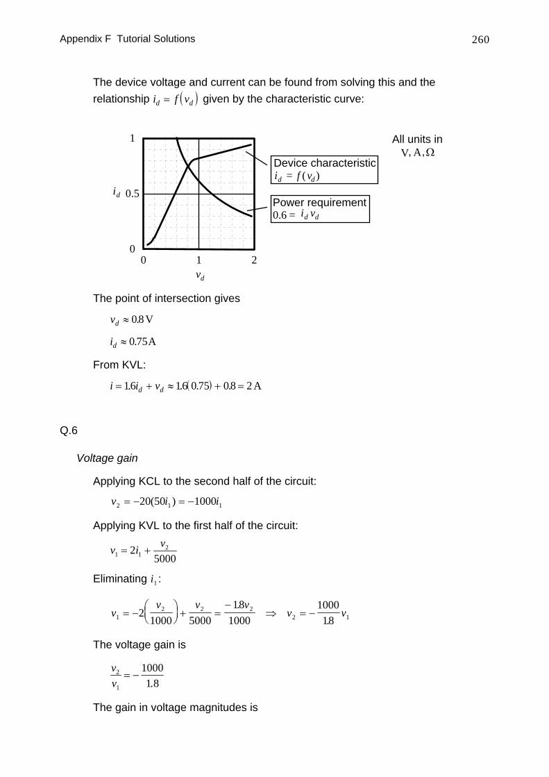
The device voltage and current can be found from solving this and the relationship ( )i f vd d= given by the characteristic curve:
vd
id
1
0.5
00 1 2
All units inV A Ω, ,
id = f (vd )Device characteristic
0.6 = id vd
Power requirement
The point of intersection gives
vd ≈ 0 8. V
id ≈ 0 75. A
From KVL:
( )i i vd d= + ≈ + =16 16 0 75 08 2. . . . A
Q.6
Voltage gain
Applying KCL to the second half of the circuit:
v i i2 1 120 50 1000= − = −( )
Applying KVL to the first half of the circuit:
v i v1 1
225000
= +
Eliminating i1 :
vv v v
v v12 2 2
2 121000 5000
181000
100018
= −⎛⎝⎜
⎞⎠⎟ + =
−⇒ = −
..
The voltage gain is
vv
2
1
10001 8
= −.
The gain in voltage magnitudes is
Appendix F Tutorial Solutions 261
vv
2
1
100018
20= =⎛⎝⎜
⎞⎠⎟.
log10001.8
dB = 55dB
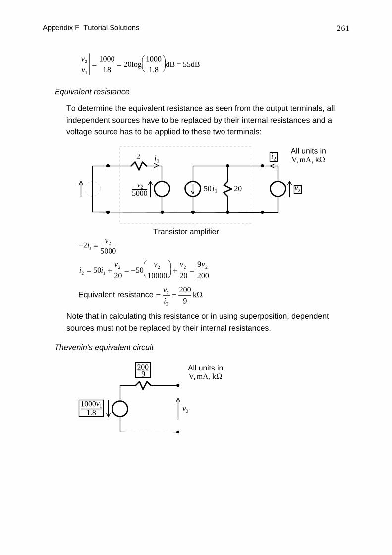
Equivalent resistance
To determine the equivalent resistance as seen from the output terminals, all independent sources have to be replaced by their internal resistances and a voltage source has to be applied to these two terminals:
Transistor amplifier
i1
20 v2
2
50 i1v2
5000
i2All units inV mA Ω, , k
− =2
500012i v
i iv v v v
2 12 2 2 250
2050
10000 209200
= + = −⎛⎝⎜
⎞⎠⎟ + =
Equivalent resistance = =vi
2
2
2009
kΩ
Note that in calculating this resistance or in using superposition, dependent sources must not be replaced by their internal resistances.
Thevenin's equivalent circuit
v2
All units inV mA Ω, , k
2009
v110001.8
Appendix F Tutorial Solutions 262
F.5 AC Circuit Analysis I
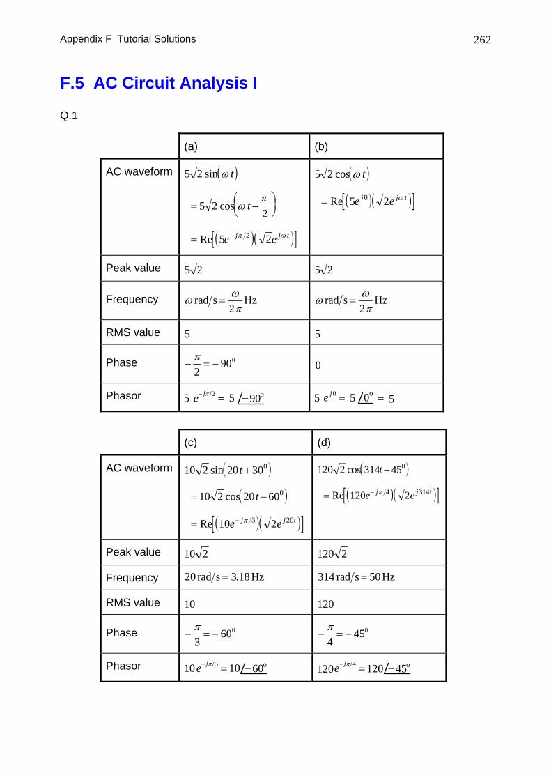
Q.1
(a) (b)
AC waveform ( )
( )( )[ ]
5 2
5 22
5 22
sin
cos
Re
ω
ωπ
π ω
t
t
e ej j t
= −⎛⎝⎜
⎞⎠⎟
= −
( )
( )( )[ ]5 2
5 20
cos
Re
ω
ω
t
e ej j t=
Peak value 5 2 5 2
Frequency ω ωπ
rad s Hz=2
ω ωπ
rad s Hz=2
RMS value 5 5
Phase − = −π2
900 0
Phasor 5 90o−5=e− jπ 2/ 5 0o5=e j 0 = 5
(c) (d)
AC waveform ( )
( )
( )( )[ ]
10 2 20 30
10 2 20 60
10 2
0
0
3 20
sin
cos
Re
t
t
e ej j t
+
= −
= − π
( )
( )( )[ ]120 2 314 45
120 2
0
4 314
cos
Re
t
e ej j t
−
= − π
Peak value 10 2 120 2
Frequency 20 3 18rad s Hz= . 314 50rad s Hz=
RMS value 10 120
Phase − = −π3
600 − = −π4
450
Phasor 10 60o−10=e− jπ 3/ 45o−120120 =e− jπ 4/
Appendix F Tutorial Solutions 263
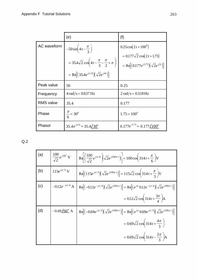
(e) (f)
AC waveform
( )( )[ ]
− −⎛⎝⎜
⎞⎠⎟
= − − +⎛⎝⎜
⎞⎠⎟
=
50 43
35 4 2 43 2
354 26 4
sin
. cos
Re .
t
t
e ej j t
π
π ππ
π
( )
( )
( )( )[ ]
0 25 2 100
0177 2 2 175
0177 2
0
1 75 2
. cos
. cos .
Re . .
t
t
e ej j t
+
= +
=
Peak value 50 0 25.
Frequency 4 0 637rad s Hz= . 2 0 318rad s Hz= .
RMS value 35 4. 0 177.
Phase π6
300= 1 75 1000. =
Phasor 30o35.435.4 =e jπ 6/ 100o0.1770.177 =e j1.75
Q.2
(a) 1002
300
e j V ( )Re cos100
22 100 314
66 100e e tj j tπ π π⎛
⎝⎜
⎞⎠⎟
⎡
⎣⎢⎤
⎦⎥= +
⎛⎝⎜
⎞⎠⎟V
(b) 115 3e jπ V ( )( )[ ]Re cos115 2 115 2 3143
3 100e e tj j tπ π π= +
⎛⎝⎜
⎞⎠⎟V
(c) − −012 4. e jπ A ( )( )[ ] ( )( )[ ]Re . Re .
. cos
− =
= +⎛⎝⎜
⎞⎠⎟
− −012 2 012 2
012 2 31434
4 100 4 100e e e e e
t
j j t j j j tπ π π π π
πA
(d) 60o0.69− A ( )( )[ ] ( )( )[ ]Re . Re .
. cos
. cos
− =
= +⎛⎝⎜
⎞⎠⎟
= −⎛⎝⎜
⎞⎠⎟
0 69 2 0 69 2
0 69 2 31443
0 69 2 31423
3 100 3 100e e e e e
t
t
j j t j j j tπ π π π π
π
πA
Appendix F Tutorial Solutions 264
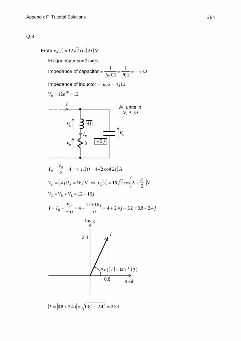
Q.3
From ( ) ( )v t tR = 12 2 2cos V
Frequency = =ω 2 rad s
Impedance of capacitor = = = −101
10 2
5j j
jω . .
Ω
Impedance of inductor = =j jω 2 4 Ω
V eRj= =12 120
3
4
I
LV
RI
RV
j
5 j−
All units inV A Ω, ,
CV
( ) ( )IV
i t tRR
R= = ⇒ =3
4 4 2 2cos A
VL ( ) ( )= = ⇒ = +⎛⎝⎜
⎞⎠⎟4 16 16 2 2
2j I j v t tR LV Vcos
π
V V V jC R L= + = +12 16
I IV
jj
jj jR
C= +−
= −+
= + − = +5
412 16
54 2 4 32 08 2 4. . . .
I
Real
Imag
2.4
)Arg [ I ] tan (−1 3=
0.8
I j= + = + =0 8 2 4 0 8 2 4 2 532 2. . . . .
Appendix F Tutorial Solutions 265
[ ] [ ]Arg ArgI j= + =⎛⎝⎜
⎞⎠⎟ =−0 8 2 4
2 40 8
1251. . tan..
.
( )I j e tj= + = ⇒ +08 2 4 2 53 2 53 2 2 1251 25. . . . cos .. A
Q.4
Impedances and phasors
( ) ( )v t t V e j= + ⇒ =50 2 1250 30 500 300
cos V V .
Impedance of inductor ( )( )= =j j1250 0 02 25. Ω
Impedance of capacitor ( )( )= = −1
1250 0 0000240
jj
.Ω
20
40j−
25jV = 50e j 30o
I
LV
RV
All units inV A Ω, ,
CV
Total impedance = + − = − = + =− −⎛⎝⎜ ⎞
⎠⎟
−20 25 40 20 15 20 15 252 215
20 36 91
0
j j j e ej tan . Ω
I Vj j
ee
ej
jj=
+ −= =
−20 25 4050
252
30
36 966 9
0
0
0
.. A
( )( )V I e eRj j= = =20 20 2 4066 9 66 90 0. . V
( )( )V j I e e eLj j j= = =25 25 2 5090 66 9 156 90 0 0. . V
( )( )V j I e e eCj j j= − = =− −40 40 2 8090 66 9 23 10 0 0. . V
Appendix F Tutorial Solutions 266
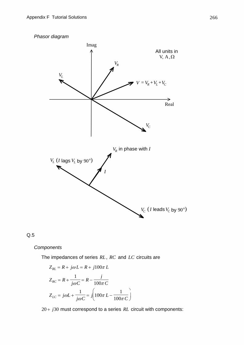
Phasor diagram
Real
Imag
LV
RV
All units inV A Ω, ,
CV
V = RV CVLV+ +
I
LV
RV in phase with I
CV CVleadsI by 90o( )
LVlagsI by 90o( )
Q.5
Components
The impedances of series RL , RC and LC circuits are
Z R j L R j LRL = + = +ω π100
Z Rj C
Rj
CRC = + = −1
100ω π
Z j Lj C
j LCLC = + = −
⎛
⎝⎜
⎞
⎠⎟ω
ωπ
π1
1001
100
20 30+ j must correspond to a series RL circuit with components:
Appendix F Tutorial Solutions 267
R j L j R L1 1 1 1100 20 30 2030
1000 0955+ = + ⇒ = = =π
πΩ and . H
10 15− j must correspond to a series RC circuit with components:
( )Rj
Cj R C2
22 2100
10 15 101
100 15212 3− = − ⇒ = = =
π πμΩ and . F
Circuit admittance
Circuit impedance ( ) ( )= = + − =
++
−
Z j j
j j
20 30 10 151
120 30
110 15
||
( )
Circuit admittance = =+
+−
=−+
+++
= − + + = +
1 120 30
110 15
20 3020 30
10 1510 15
0 0154 0 0231 0 0308 0 0462 0 0462 0 0231
2 2 2 2Z j jj j
j j j. . . . . . Ω−1
Power factor ( ) ( )[ ]
( ) ( )( ) ( )
Power factor
value
/=
= −
=− >− <
⎧⎨⎩
cos
,,
Arg Arg
leading laggingleading Arg Arglagging Arg Arg
I V
I VI V
00
( ) ( ) ( )
( )
Arg Arg Arg Arg Arg
Arg tan-1
I VIV Z
Z
j
− =⎛⎝⎜
⎞⎠⎟ =
⎛⎝⎜
⎞⎠⎟ = −
= + =⎛⎝⎜
⎞⎠⎟ =
1
0 0462 0 02310 02310 0462
0 464. ...
.
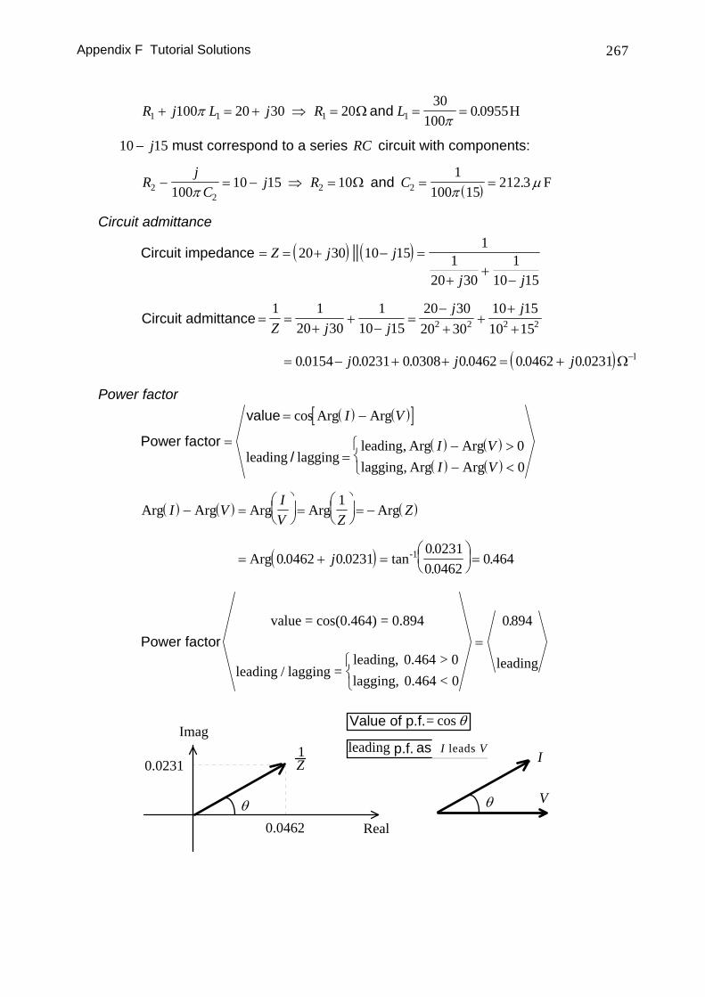
Power factorvalue = cos(0.464) = 0.894
leading / lagging =leading, 0.464 > 0lagging, 0.464 < 0
leading⎧⎨⎩
=0 894.
Real
Imag1Z
θ V
I
Value of p.f.= cos θ
p.f. lags I Vleading as
0.0462
0.0231
θ
I leads V
Appendix F Tutorial Solutions 268
F.6 AC Circuit Analysis II
Q.1
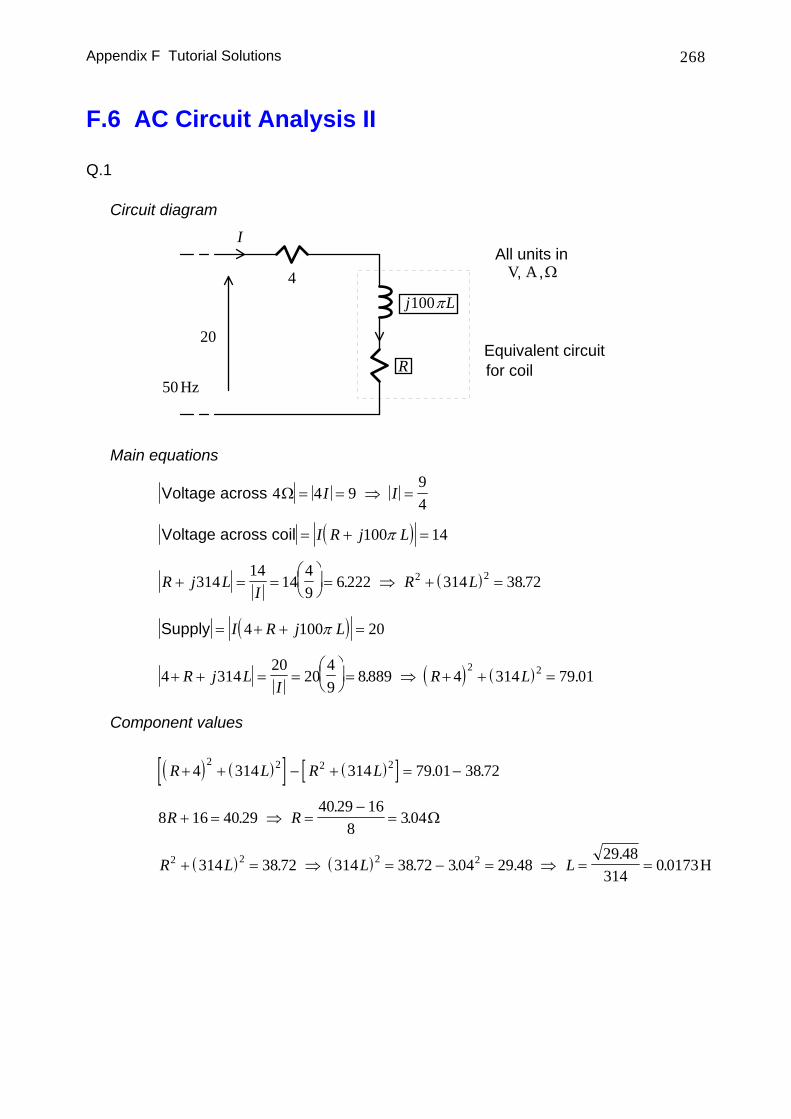
Circuit diagram
IAll units in
V A Ω, ,
REquivalent circuitfor coil
4
20
50 Hz
Lj100π
Main equations
Voltage across 4 4 994
Ω = = ⇒ =I I
( )Voltage across coil = + =I R j L100 14π
( )R j LI
R L+ = =⎛⎝⎜
⎞⎠⎟ = ⇒ + =314
1414
49
6 222 314 38 722 2. .
( )Supply = + + =I R j L4 100 20π
( ) ( )4 31420
2049
8 889 4 314 79 012 2+ + = =
⎛⎝⎜
⎞⎠⎟ = ⇒ + + =R j L
IR L. .
Component values
( ) ( )[ ] ( )[ ]R L R L+ + − + = −4 314 314 79 01 38 722 2 2 2 . .
8 16 40 2940 29 16
83 04R R+ = ⇒ =
−=.
.. Ω
( ) ( )R L L L2 2 2 2314 38 72 314 38 72 3 04 29 4829 48314
0 0173+ = ⇒ = − = ⇒ = =. . . ..
. H
Appendix F Tutorial Solutions 269
Power and power factor
Power absorbed by coil ( )= =⎛⎝⎜
⎞⎠⎟ =I R2
294
304 154. . W
( ) ( )[ ]( ) ( )( ) ( )
Power factor
value current voltage
/current voltagecurrent voltage
=
= −
=− >− <
⎧⎨⎩
cos
,,
Arg Arg
leading laggingleading Arg Arglagging Arg Arg
00
( ) ( )
( )
Arg Arg Arg
Arg Arg
current voltagecurrentvoltage
ImpedanceImpedance
− =⎛⎝⎜
⎞⎠⎟
=⎛⎝⎜
⎞⎠⎟ = −
1
( )[ ]( )( )
Power factor
value impedance
/impedanceimpedance
=
=
=<>
⎧⎨⎩
cos
,,
Arg
leading laggingleading Arglagging Arg
00
( ) ( ) ( )
( )
Arg Arg Arg
Arg tan-1
impedance = + + = + + ×
= + =⎛⎝⎜
⎞⎠⎟ =
R j L j
j
4 314 304 4 314 0 0173
7 04 5435437 04
0 657
. .
. ...
.
( )
Power factor
value
/=
= =
=<>
⎧⎨⎩
=
cos . .
, ., .
.0 657 0 792
0 657 00 657 0
0 792
leading laggingleadinglagging
lagging
Appendix F Tutorial Solutions 270
Q.2
Load current
All units inV A Ω, ,
Z
IZ
Load50 Hz
2000V =
Load power factoractual power
apparent power= ⇒ = ⇒ =05
100002000
10.I
IZ
Z A
All units inV A Ω, ,
IZ
2000V =
lagsIZ VLagging power factor
( ) ( )[ ]( ) ( )
( ) ( )( )
( )
0 5 0 50
0 5 1050
105
1
. cos .
cos . .
.
lagging Arg ArgArg Arg
ArgArg
Arg
loadp.f. ⇒− =
− <
⇒= ± = ±<
⇒ = −
−
I VI V
II
I
Z
Z
Z
Z
Z
[ ]I I e eZ Zj I jZ= = −Arg A10 1 05.
Power factor improvement
Z
IZ
Load
I
IC
2000
50 HzC
1j 314
( )( )I j C j CC = =314 2000 628000
( )I I I e j C j CZ Cj= + = + = + −−10 628000 5 62800 8 661 05. .
Appendix F Tutorial Solutions 271
IZ
2000V =
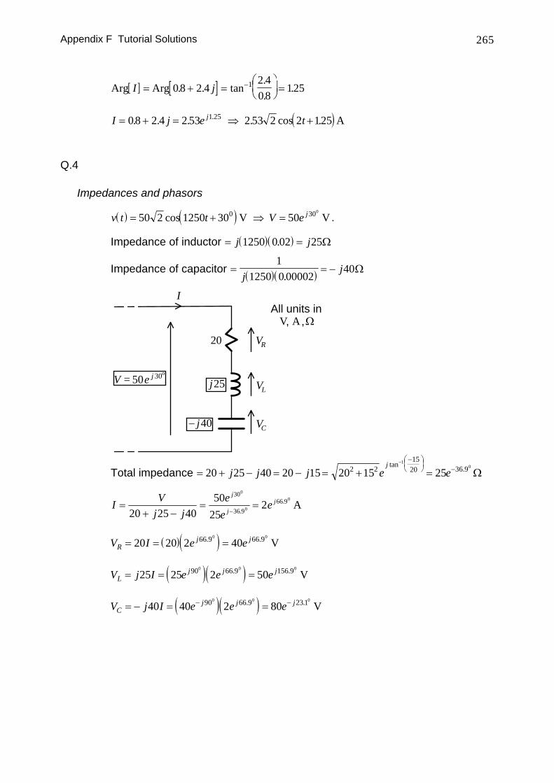
IC
I
( ) ( )( ) ( )
( )( )
( )
( )
-1
cos Arg Arg 0.9 Arg 0.4510.9 laggingArg 0Arg Arg 0
628000 8.66Arg 0.451 tan 0.4515
8.66 5 tan 0.4519.9 F
628000
I V III V
CI
C μ
− =⎡ ⎤ = ±⎣ ⎦⇒ ⇒<− <
−⎛ ⎞⇒ = − ⇒ = −⎜ ⎟⎝ ⎠
+ −⇒ = =
overall p.f.
( ) ( )[ ]( ) ( )
( )unityoverall p.f. ⇒
− =− =
⇒ =
⇒−⎛
⎝⎜
⎞⎠⎟ = ⇒ = =
cos
. ..
Arg ArgArg Arg
Arg
tan F = 13.8 F-1
I VI V
I
CC
10
0
628000 8 665
08 66
6280000 0000138 μ
( ) ( )[ ]( ) ( )
( )( )
( )
( )F19.8=
tanArg
Arg
Arg
ArgArg
ArgArgleading
μ628000
644.0tan566.8
644.05
66.8628000644.0
0644.0
08.0cos8.0
1
+=⇒
=⎟⎠⎞
⎜⎝⎛ −
⇒=⇒
>±=
⇒>−
=−⇒
−
C
CI
II
VIVI
p.f.overall
Appendix F Tutorial Solutions 272
Q.3
Power
Electrical system
j+
V R= jZ + X
All units inV A Ω, ,IZ
VZ
a b
( ) ( ) ( ) ( )IV
a jb R jXV
a R j b XZ =+ + +
=+ + +
( )V I R jXZ Z= +
[ ] ( )[ ][ ]
( ) ( ) ( ) ( )
Power absorbed= = = +
= + =
=+ + +
=+ + +
∗p I V I R jX
I R jX R I
RV
a R j b XRV
a R b X
Z Z Z
Z Z
Re Re
Re
2
2 2
2 2
2 2
Maximum power transfer
For maximum p, the denominator should be as small as possible. As the numerator does not depend on X and the smallest value for ( )b X+ is 0 , maximum power will be absorbed if
X b= −
so that
( )p
V R
a R=
+
2
2
Differentiating:
( ) ( ) ( )dpdR
Va R
R
a RV
a R
a R=
+−
+
⎡
⎣⎢⎢
⎤
⎦⎥⎥=
−
+
⎡
⎣⎢⎢
⎤
⎦⎥⎥
22 3
23
1 2
Thus, maximum p occurs when
R a=
Appendix F Tutorial Solutions 273
and the maximum power transferable is
( )p
V R
R R
VR
Va
=+
= =2
2
2 2
4 4W
In general, maximum power transfer occurs when the load impedance is equal to the conjugate of the Thevenin's or Norton's impedance. When this occurs, the total impedance is purely resistive and the current and voltage in the circuit are in phase:
j+
V=Z j−= j+( )*
Maximum power transfer
ba
baba
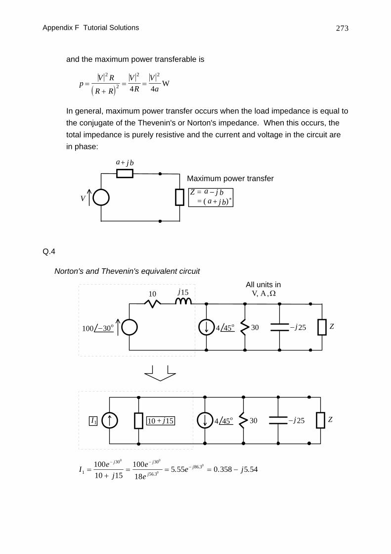
Q.4
Norton's and Thevenin's equivalent circuit
10 j15
30 j25−
All units inV A Ω, ,
Z45o4100 30o−
30 j25− Z45o410 j15+I1
I ej
ee
e jj j
jj
1
30 30
56 386 3100
10 1510018
5 55 0 358 5 540 0
0
0
=+
= = = −− −
−
... . .
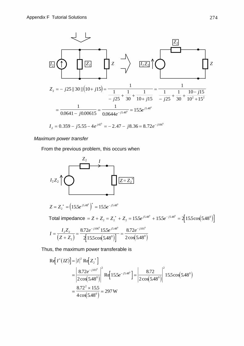
Appendix F Tutorial Solutions 274
ZI2 Z2 Z
Z2
I2 Z2
( )Z j j
j j jj
j ee
jj
2
2 2
5 485 48
25 30 10 151
125
130
110 15
1125
130
10 1510 15
10 0641 0 00615
10 0644
1550
0
= − + =
−+ +
+
=
−+ +
−+
=−
= =−
|| ||
. . ..
..
I j e j ej j2
45 1060 359 5 55 4 2 47 8 36 8 720 0
= − − = − − = −. . . . .
Maximum power transfer
From the previous problem, this occurs when
Z2
I2 Z2 Z = Z2*
I
( )Z Z e ej j= = =∗ ∗ −2
5 48 5 48155 1550 0
. .. .
Total impedance ( )[ ]= + = + = + =∗ −Z Z Z Z e ej j2 2 2
5 48 5 48 0155 155 2 155 5 480 0
. . . cos .. .
( ) ( )[ ] ( )II Z
Z Ze e ej j j
=+
= =− −
2 2
2
106 5 48
0
101
0
8 72 1552 155 5 48
8 722 5 48
0 0 0
. .. cos .
.cos .
.
Thus, the maximum power transferable is
( )[ ] [ ]
( ) [ ] ( ) ( )
( )
Re Re
.cos .
Re ..
cos .. cos .
. .cos .
.
I IZ I Z
ee
jj
∗ ∗
−−
=
= =
=×
=
22
101
0
2
5 480
2
0
2
0
8 722 548
1558 72
2 548155 548
8 72 1554 548
297
0
0
W
Appendix F Tutorial Solutions 275
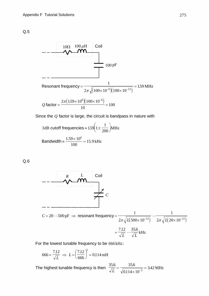
Q.5
Ω10 H100 μ
100 pF
Coil
( )( )Resonant frequency =
× ×=
− −
1
2 100 10 100 10159
6 12π. MHz
( )( )Q factor =
× ×=
−2 159 10 100 1010
1006 6π .
Since the Q factor is large, the circuit is bandpass in nature with
3 159 11
200dB MHz cutoff frequencies ≈ ±
⎛⎝⎜
⎞⎠⎟.
Bandwidth ≈×
=1 59 10
10015 9
6. . kHz
Q.6
CoilR L
C
( ) ( )C
L L
L L
= ⇒ =× ×
=
− −20 500
1
2 500 10
1
2 20 10
712 356
12 12pF
kHz
resonant frequencyπ π
. .
For the lowest tunable frequency to be 666 kHz:
666712 712
6660114
2
= ⇒ =⎛⎝⎜
⎞⎠⎟ =
. ..
LL mH
The highest tunable frequency is then 356 356
0114 10342
3
. .
..
L=
×=
−MHz


![[PPT]Kirchoff’s Laws - NAU jan.ucc.nau.edu web serversh295/EE188/slides/KirchoffLaws.ppt · Web viewKirchoff’s Laws Chapter 3 Example Circuit Writing KVL, I1∙14.4Ω – 50 v](https://static.fdocument.org/doc/165x107/5ab07e597f8b9ac66c8b4db2/pptkirchoffs-laws-nau-januccnauedu-web-sh295ee188slideskirchofflawspptweb.jpg)


![Supporting Information - PNAS · russi–Beadle Ringer’s solution [129 mM NaCl, 4.7 mM KCl, 1.9 mM CaCl 2, 10 mM Hepes (pH 6.9)] for nonhypotonic treatment while in the presence](https://static.fdocument.org/doc/165x107/5eb46bd2a4d6d71905681da8/supporting-information-pnas-russiabeadle-ringeras-solution-129-mm-nacl-47.jpg)


![maredu.gunet.gr · Web viewFire Protection and Fire-fighting - B2/315. Damage Control – B2/419. Grounding – B2/522. SAR onboard communication activities – B2/64. D] Revision](https://static.fdocument.org/doc/165x107/5f155149e90a79017779b0d2/web-view-fire-protection-and-fire-fighting-b2315-damage-control-a-b2419.jpg)