Duplex filter - EPG · Element model Standard adhesive T = 100 °C = 0 ... Duplex filter without...
18
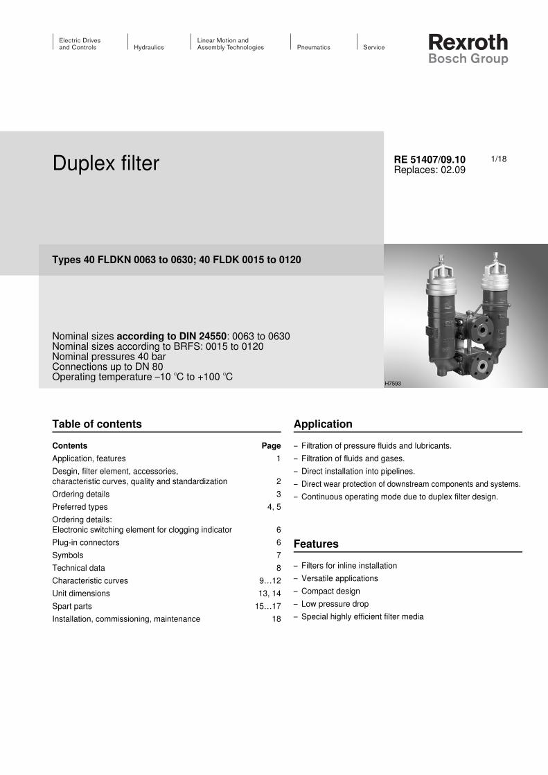
1/18 Duplex filter Types 40 FLDKN 0063 to 0630; 40 FLDK 0015 to 0120 Nominal sizes according to DIN 24550: 0063 to 0630 Nominal sizes according to BRFS: 0015 to 0120 Nominal pressures 40 bar Connections up to DN 80 Operating temperature –10 ℃ to +100 ℃ RE 51407/09.10 Replaces: 02.09 Table of contents Application – Filtration of pressure fluids and lubricants. – Filtration of fluids and gases. – Direct installation into pipelines. – Direct wear protection of downstream components and systems. – Continuous operating mode due to duplex filter design. Contents Page Application, features 1 Desgin, filter element, accessories, characteristic curves, quality and standardization 2 Ordering details 3 Preferred types 4, 5 Ordering details: Electronic switching element for clogging indicator 6 Plug-in connectors 6 Symbols 7 Technical data 8 Characteristic curves 9…12 Unit dimensions 13, 14 Spart parts 15…17 Installation, commissioning, maintenance 18 Features – Filters for inline installation – Versatile applications – Compact design – Low pressure drop – Special highly efficient filter media H7593
Transcript of Duplex filter - EPG · Element model Standard adhesive T = 100 °C = 0 ... Duplex filter without...
1/18Duplex filter
Types 40 FLDKN 0063 to 0630; 40 FLDK 0015 to 0120
Nominal sizes according to DIN 24550: 0063 to 0630Nominal sizes according to BRFS: 0015 to 0120Nominal pressures 40 barConnections up to DN 80Operating temperature –10 ℃ to +100 ℃
RE 51407/09.10Replaces: 02.09
Table of contents Application– Filtration of pressure fluids and lubricants.– Filtration of fluids and gases.– Direct installation into pipelines.– Direct wear protection of downstream components and systems.– Continuous operating mode due to duplex filter design.
Contents PageApplication, features 1Desgin, filter element, accessories, characteristic curves, quality and standardization 2Ordering details 3Preferred types 4, 5Ordering details: Electronic switching element for clogging indicator 6Plug-in connectors 6Symbols 7Technical data 8Characteristic curves 9…12Unit dimensions 13, 14Spart parts 15…17Installation, commissioning, maintenance 18
Features– Filters for inline installation– Versatile applications– Compact design– Low pressure drop– Special highly efficient filter media
H7593
2/18 Bosch Rexroth AG Hydraulics 40 FLDKN 0063 - 0630; 40 FLDK 0015 - 0120 RE 51407/09.10
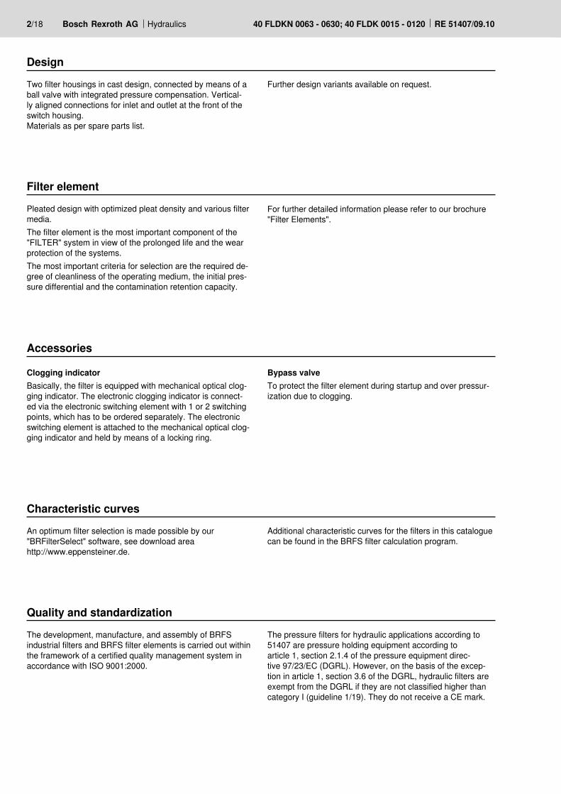
DesignTwo filter housings in cast design, connected by means of a ball valve with integrated pressure compensation. Vertical-ly aligned connections for inlet and outlet at the front of the switch housing. Materials as per spare parts list.
Filter elementPleated design with optimized pleat density and various filter media. The filter element is the most important component of the "FILTER" system in view of the prolonged life and the wear protection of the systems. The most important criteria for selection are the required de-gree of cleanliness of the operating medium, the initial pres-sure differential and the contamination retention capacity.
For further detailed information please refer to our brochure "Filter Elements".
Accessories
Clogging indicatorBasically, the filter is equipped with mechanical optical clog-ging indicator. The electronic clogging indicator is connect-ed via the electronic switching element with 1 or 2 switching points, which has to be ordered separately. The electronic switching element is attached to the mechanical optical clog-ging indicator and held by means of a locking ring.
Bypass valve To protect the filter element during startup and over pressur-ization due to clogging.
Further design variants available on request.
Quality and standardizationThe development, manufacture, and assembly of BRFSindustrial filters and BRFS filter elements is carried out within the framework of a certified quality management system in accordance with ISO 9001:2000.
The pressure filters for hydraulic applications according to 51407 are pressure holding equipment according to article 1, section 2.1.4 of the pressure equipment direc-tive 97/23/EC (DGRL). However, on the basis of the excep-tion in article 1, section 3.6 of the DGRL, hydraulic filters are exempt from the DGRL if they are not classified higher than category I (guideline 1/19). They do not receive a CE mark.
Characteristic curvesAn optimum filter selection is made possible by our "BRFilterSelect" software, see download area http://www.eppensteiner.de.
Additional characteristic curves for the filters in this catalogue can be found in the BRFS filter calculation program.
Hydraulics Bosch Rexroth AGRE 51407/09.10 40 FLDKN 0063 - 0630; 40 FLDK 0015 - 0120 3/18
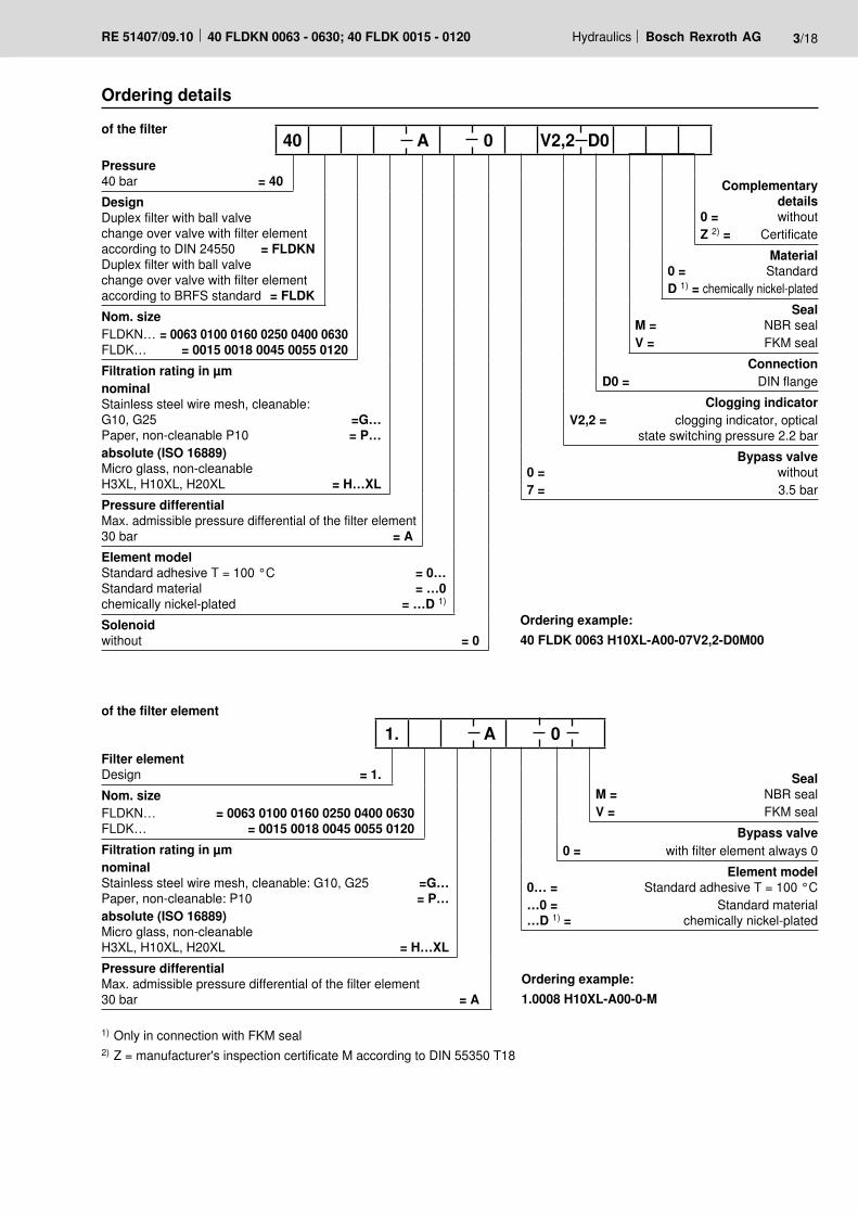
Pressure40 bar = 40
DesignDuplex filter with ball valvechange over valve with filter element according to DIN 24550 = FLDKNDuplex filter with ball valvechange over valve with filter element according to BRFS standard = FLDKNom. sizeFLDKN… = 0063 0100 0160 0250 0400 0630 FLDK… = 0015 0018 0045 0055 0120Filtration rating in µmnominalStainless steel wire mesh, cleanable:G10, G25 =G…Paper, non-cleanable P10 = P…absolute (ISO 16889)Micro glass, non-cleanableH3XL, H10XL, H20XL = H…XLPressure differentialMax. admissible pressure differential of the filter element30 bar = AElement modelStandard adhesive T = 100 °C = 0…Standard material = …0chemically nickel-plated = …D 1)
Solenoidwithout = 0
Complementary details
0 = withoutZ 2) = Certificate
Material0 = StandardD 1) = chemically nickel-plated
SealM = NBR sealV = FKM seal
ConnectionD0 = DIN flange
Clogging indicatorV2,2 = clogging indicator, optical
state switching pressure 2.2 barBypass valve
0 = without7 = 3.5 bar
40 A 0 V2,2 D0
1) Only in connection with FKM seal 2) Z = manufacturer's inspection certificate M according to DIN 55350 T18
Ordering example:40 FLDK 0063 H10XL-A00-07V2,2-D0M00
Filter elementDesign = 1.Nom. sizeFLDKN… = 0063 0100 0160 0250 0400 0630FLDK… = 0015 0018 0045 0055 0120Filtration rating in µmnominalStainless steel wire mesh, cleanable: G10, G25 =G…Paper, non-cleanable: P10 = P…absolute (ISO 16889)Micro glass, non-cleanableH3XL, H10XL, H20XL = H…XLPressure differentialMax. admissible pressure differential of the filter element30 bar = A
SealM = NBR sealV = FKM seal
Bypass valve0 = with filter element always 0
Element model0… = Standard adhesive T = 100 °C…0 = Standard material…D 1) = chemically nickel-plated
1. A 0
Ordering example:1.0008 H10XL-A00-0-M
Ordering details
of the filter element
of the filter
4/18 Bosch Rexroth AG Hydraulics 40 FLDKN 0063 - 0630; 40 FLDK 0015 - 0120 RE 51407/09.10
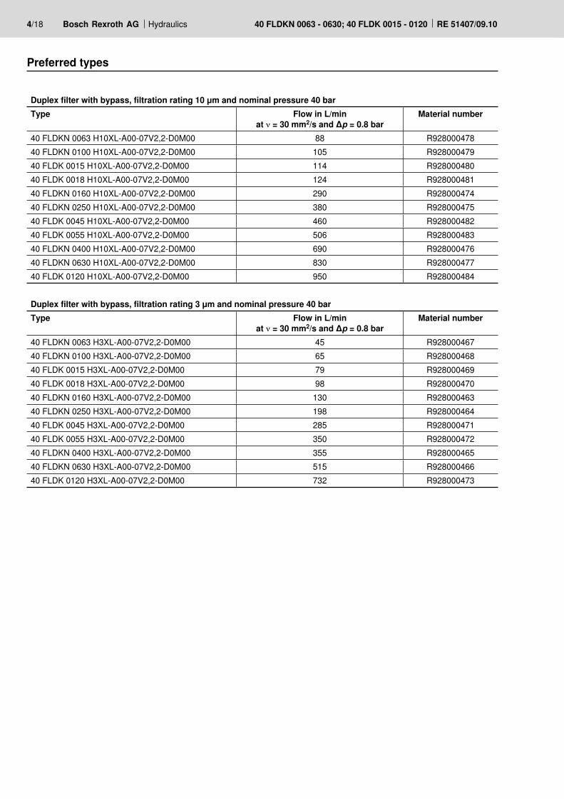
Preferred types
Duplex filter with bypass, filtration rating 10 μm and nominal pressure 40 barType Flow in L/min
at ν = 30 mm2/s and Δp = 0.8 barMaterial number
40 FLDKN 0063 H10XL-A00-07V2,2-D0M00 88 R92800047840 FLDKN 0100 H10XL-A00-07V2,2-D0M00 105 R92800047940 FLDK 0015 H10XL-A00-07V2,2-D0M00 114 R92800048040 FLDK 0018 H10XL-A00-07V2,2-D0M00 124 R92800048140 FLDKN 0160 H10XL-A00-07V2,2-D0M00 290 R92800047440 FLDKN 0250 H10XL-A00-07V2,2-D0M00 380 R92800047540 FLDK 0045 H10XL-A00-07V2,2-D0M00 460 R92800048240 FLDK 0055 H10XL-A00-07V2,2-D0M00 506 R92800048340 FLDKN 0400 H10XL-A00-07V2,2-D0M00 690 R92800047640 FLDKN 0630 H10XL-A00-07V2,2-D0M00 830 R92800047740 FLDK 0120 H10XL-A00-07V2,2-D0M00 950 R928000484
Duplex filter with bypass, filtration rating 3 μm and nominal pressure 40 barType Flow in L/min
at ν = 30 mm2/s and Δp = 0.8 barMaterial number
40 FLDKN 0063 H3XL-A00-07V2,2-D0M00 45 R92800046740 FLDKN 0100 H3XL-A00-07V2,2-D0M00 65 R92800046840 FLDK 0015 H3XL-A00-07V2,2-D0M00 79 R92800046940 FLDK 0018 H3XL-A00-07V2,2-D0M00 98 R92800047040 FLDKN 0160 H3XL-A00-07V2,2-D0M00 130 R92800046340 FLDKN 0250 H3XL-A00-07V2,2-D0M00 198 R92800046440 FLDK 0045 H3XL-A00-07V2,2-D0M00 285 R92800047140 FLDK 0055 H3XL-A00-07V2,2-D0M00 350 R92800047240 FLDKN 0400 H3XL-A00-07V2,2-D0M00 355 R92800046540 FLDKN 0630 H3XL-A00-07V2,2-D0M00 515 R92800046640 FLDK 0120 H3XL-A00-07V2,2-D0M00 732 R928000473

Hydraulics Bosch Rexroth AGRE 51407/09.10 40 FLDKN 0063 - 0630; 40 FLDK 0015 - 0120 5/18
Preferred types
Duplex filter without bypass, filtration rating 10 μm and nominal pressure 40 barType Flow in L/min
at ν = 30 mm2/s and Δp = 0.8 barMaterial number
40 FLDKN 0063 H10XL-A00-00V2,2-D0M00 88 R92802026140 FLDKN 0100 H10XL-A00-00V2,2-D0M00 105 R92802026240 FLDK 0015 H10XL-A00-00V2,2-D0M00 114 R92802026340 FLDK 0018 H10XL-A00-00V2,2-D0M00 124 R92802026440 FLDKN 0160 H10XL-A00-00V2,2-D0M00 290 R92802025740 FLDKN 0250 H10XL-A00-00V2,2-D0M00 380 R92802025840 FLDK 0045 H10XL-A00-00V2,2-D0M00 460 R92802026540 FLDK 0055 H10XL-A00-00V2,2-D0M00 506 R92802026640 FLDKN 0400 H10XL-A00-00V2,2-D0M00 690 R92802025940 FLDKN 0630 H10XL-A00-00V2,2-D0M00 830 R92802026040 FLDK 0120 H10XL-A00-00V2,2-D0M00 950 R928020267
Duplex filter without bypass, filtration rating 3 μm and nominal pressure 40 barType Flow in L/min
at ν = 30 mm2/s and Δp = 0.8 barMaterial number
40 FLDKN 0063 H3XL-A00-00V2,2-D0M00 45 R92802025040 FLDKN 0100 H3XL-A00-00V2,2-D0M00 65 R92802025140 FLDK 0015 H3XL-A00-00V2,2-D0M00 79 R92802025240 FLDK 0018 H3XL-A00-00V2,2-D0M00 98 R92802025340 FLDKN 0160 H3XL-A00-00V2,2-D0M00 130 R92802024640 FLDKN 0250 H3XL-A00-00V2,2-D0M00 198 R92802024740 FLDK 0045 H3XL-A00-00V2,2-D0M00 285 R92802025440 FLDK 0055 H3XL-A00-00V2,2-D0M00 350 R92802025540 FLDKN 0400 H3XL-A00-00V2,2-D0M00 355 R92802024840 FLDKN 0630 H3XL-A00-00V2,2-D0M00 515 R92802024940 FLDK 0120 H3XL-A00-00V2,2-D0M00 732 R928020256
54
M12
x 1
Ø19
,6
[2.12]
[0.7
7]
M12
x 1
Ø19
,6
41,5 [1.63]
[0.7
7]
6/18 Bosch Rexroth AG Hydraulics 40 FLDKN 0063 - 0630; 40 FLDK 0015 - 0120 RE 51407/09.10
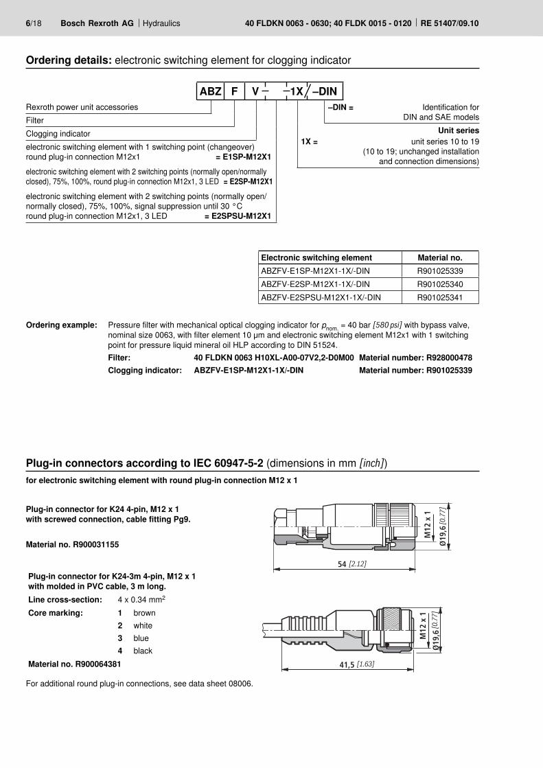
Ordering example: Pressure filter with mechanical optical clogging indicator for pnom. = 40 bar [580 psi] with bypass valve, nominal size 0063, with filter element 10 μm and electronic switching element M12x1 with 1 switching point for pressure liquid mineral oil HLP according to DIN 51524.
Filter: 40 FLDKN 0063 H10XL-A00-07V2,2-D0M00 Material number: R928000478 Clogging indicator: ABZFV-E1SP-M12X1-1X/-DIN Material number: R901025339
Plug-in connectors according to IEC 60947-5-2 (dimensions in mm [inch])
Plug-in connector for K24 4-pin, M12 x 1with screwed connection, cable fitting Pg9.
Material no. R900031155
Plug-in connector for K24-3m 4-pin, M12 x 1with molded in PVC cable, 3 m long.Line cross-section: 4 x 0.34 mm2
Core marking: 1234
brownwhiteblueblack
Material no. R900064381
for electronic switching element with round plug-in connection M12 x 1
For additional round plug-in connections, see data sheet 08006.
Ordering details: electronic switching element for clogging indicator
Rexroth power unit accessories FilterClogging indicatorelectronic switching element with 1 switching point (changeover) round plug-in connection M12x1 = E1SP-M12X1electronic switching element with 2 switching points (normally open/normally closed), 75%, 100%, round plug-in connection M12x1, 3 LED = E2SP-M12X1electronic switching element with 2 switching points (normally open/normally closed), 75%, 100%, signal suppression until 30 °Cround plug-in connection M12x1, 3 LED = E2SPSU-M12X1
–DIN = Identification for DIN and SAE models
Unit series1X = unit series 10 to 19
(10 to 19; unchanged installation and connection dimensions)
ABZ F V 1X –DIN
Electronic switching element Material no.ABZFV-E1SP-M12X1-1X/-DIN R901025339ABZFV-E2SP-M12X1-1X/-DIN R901025340ABZFV-E2SPSU-M12X1-1X/-DIN R901025341
100%2475%
1(+)
3(–)
2K2100%
4
K175% 1(+)
3(–)K2K1
S175% S2-100%
2
4
1(+)
3(–)
Hydraulics Bosch Rexroth AGRE 51407/09.10 40 FLDKN 0063 - 0630; 40 FLDK 0015 - 0120 7/18
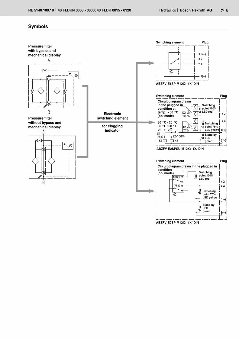
Pressure filterwith bypass andmechanical display
Pressure filterwithout bypass andmechanical display
Symbols
Switching element Plug
Switchingpoint 100% LED red
Switchingpoint 75% LED yellowStand-by LED green
Circuit diagram drawn in the plugged in condition at temp. > 30 °C (op. mode)
30 °C / 20 °C86 °F / 68 °Fon / off
Electronic switching element
for cloggingindicator
ABZFV-E1SP-M12X1-1X/-DIN
ABZFV-E2SPSU-M12X1-1X/-DIN
ABZFV-E2SP-M12X1-1X/-DIN
Switching element Plug
Switchingpoint 100% LED red
Switchingpoint 75% LED yellow
Stand-by LED green
Circuit diagram drawn in the plugged in condition (op. mode)
Switching element Plug
8/18 Bosch Rexroth AG Hydraulics 40 FLDKN 0063 - 0630; 40 FLDK 0015 - 0120 RE 51407/09.10
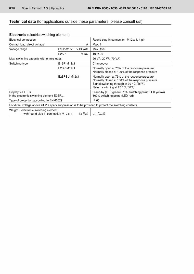
Electronic (electric switching element) Electrical connection Round plug-in connection M12 x 1, 4-pinContact load, direct voltage A Max. 1Voltage range E1SP-M12x1 V DC/AC Max. 150
E2SP V DC 10 to 30Max. switching capacity with ohmic loads 20 VA; 20 W; (70 VA)Switching type E1SP-M12x1 Changeover
E2SP-M12x1 Normally open at 75% of the response pressure, Normally closed at 100% of the response pressure
E2SPSU-M12x1 Normally open at 75% of the response pressure,Normally closed at 100% of the response pressureSignal switching through at 30 °C [86 °F], Return switching at 20 °C [68 °F]
Display via LEDs in the electronic switching element E2SP...
Stand-by (LED green); 75% switching point (LED yellow)100% switching point (LED red)
Type of protection according to EN 60529 IP 65For direct voltage above 24 V a spark suppression is to be provided to protect the switching contacts.
Technical data (for applications outside these parameters, please consult us!)
Weight electronic switching element: – with round plug-in connection M12 x 1 kg [lbs] 0.1 [0.22]

30025015010050
8
7
6
5
4
3
2
1
0 200 40024016080
8
7
6
5
4
3
2
1
0 320
12080 10020
7
6
5
4
3
2
1
0 6040908070502010
8
7
6
5
4
3
2
1
0 604030
14080 10020
6
5
4
3
2
1
0 6040 120 14080 10020
5
4
3
2
1
0 6040 120 160 180
Hydraulics Bosch Rexroth AGRE 51407/09.10 40 FLDKN 0063 - 0630; 40 FLDK 0015 - 0120 9/18
Diffe
rent
ial p
ress
ure
[bar
] →
Flow [L/min] →
Diffe
rent
ial p
ress
ure
[bar
] →
Flow [L/min] →
0160 0250
0063
Diffe
rent
ial p
ress
ure
[bar
] →
Flow [L/min] →Di
ffere
ntia
l pre
ssur
e [b
ar] →
Flow [L/min] →
0100
Diffe
rent
ial p
ress
ure
[bar
] →
Flow [L/min] →
Diffe
rent
ial p
ress
ure
[bar
] →
Flow [L/min] →
0015 0018
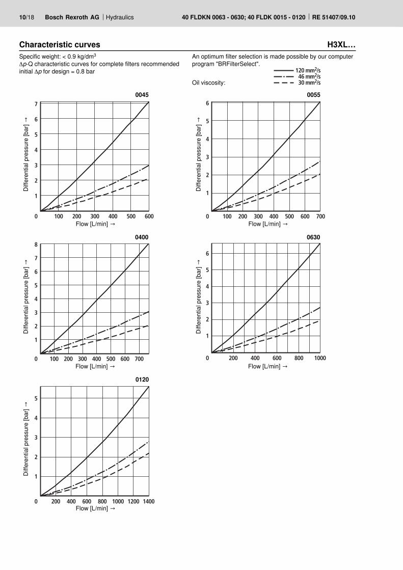
An optimum filter selection is made possible by our computerprogram "BRFilterSelect".
Oil viscosity:
Characteristic curves H3XL…Specific weight: < 0.9 kg/dm3 Δp-Q characteristic curves for complete filters recommended initial Δp for design = 0.8 bar 120 mm2/s
46 mm2/s30 mm2/s
600200
5
4
3
2
1
0 400 1400800 1000 1200
500300200100
7
6
5
4
3
2
1
0 400 600 500300200100
6
5
4
3
2
1
0 400 700600
500300200100
8
6
5
4
3
2
1
0 400 700
7
600 600200
6
5
4
3
2
1
0 400 1000800
10/18 Bosch Rexroth AG Hydraulics 40 FLDKN 0063 - 0630; 40 FLDK 0015 - 0120 RE 51407/09.10
0120
Diffe
rent
ial p
ress
ure
[bar
] →
Flow [L/min] →
0045
Diffe
rent
ial p
ress
ure
[bar
] →
Flow [L/min] →
Diffe
rent
ial p
ress
ure
[bar
] →
Flow [L/min] →
0055
0400
Diffe
rent
ial p
ress
ure
[bar
] →
Flow [L/min] →
Diffe
rent
ial p
ress
ure
[bar
] →
Flow [L/min] →
0630
An optimum filter selection is made possible by our computerprogram "BRFilterSelect".
Oil viscosity:
Characteristic curves H3XL…Specific weight: < 0.9 kg/dm3 Δp-Q characteristic curves for complete filters recommended initial Δp for design = 0.8 bar 120 mm2/s
46 mm2/s30 mm2/s
160
3,5
3,0
2,0
1,5
0,5
0 80
4,0
1,0
240 320
2,5
200
3,5
3,0
2,0
1,5
0,5
0 100
4,0
1,0
300 500
2,5
600400
1501251007525
3,2
2,4
2,0
1,6
1,2
0,4
0 50
2,8
0,8
12080 10020
4
3
2
1
0 6040
160100806020
3,2
2,4
2,0
1,6
1,2
0,4
0 40
2,8
0,8
120 140 14080 10020
5
4
3
2
1
0 6040 120 160 180
Hydraulics Bosch Rexroth AGRE 51407/09.10 40 FLDKN 0063 - 0630; 40 FLDK 0015 - 0120 11/18
Diffe
rent
ial p
ress
ure
[bar
] →
Flow [L/min] →
Diffe
rent
ial p
ress
ure
[bar
] →
Flow [L/min] →
0160 0250
0063
Diffe
rent
ial p
ress
ure
[bar
] →
Flow [L/min] →Di
ffere
ntia
l pre
ssur
e [b
ar] →
Flow [L/min] →
0100
Diffe
rent
ial p
ress
ure
[bar
] →
Flow [L/min] →
Diffe
rent
ial p
ress
ure
[bar
] →
Flow [L/min] →
0015 0018
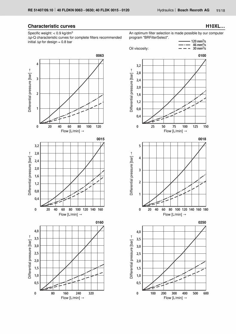
An optimum filter selection is made possible by our computerprogram "BRFilterSelect".
Oil viscosity:
Characteristic curves H10XL…Specific weight: < 0.9 kg/dm3 Δp-Q characteristic curves for complete filters recommended initial Δp for design = 0.8 bar 120 mm2/s
46 mm2/s30 mm2/s
800400
2,4
2,0
1,6
1,2
0,4
0 200
3,2
0,8
600
2,8
1000 14001200
700400300100
2,4
2,0
1,6
1,2
0,4
0 200
2,8
0,8
500 600
3,2
500300200100
6
5
4
3
2
1
0 400 700600
800400300100
2,4
2,0
1,6
1,2
0,4
0 200
3,2
0,8
500 600
3,6
2,8
700 900 800400
2,4
2,0
1,6
1,2
0,4
0 200
3,2
0,8
600
2,8
1000 1200
12/18 Bosch Rexroth AG Hydraulics 40 FLDKN 0063 - 0630; 40 FLDK 0015 - 0120 RE 51407/09.10
0120
Diffe
rent
ial p
ress
ure
[bar
] →
Flow [L/min] →
0045
Diffe
rent
ial p
ress
ure
[bar
] →
Flow [L/min] →
Diffe
rent
ial p
ress
ure
[bar
] →
Flow [L/min] →
0055
0400
Diffe
rent
ial p
ress
ure
[bar
] →
Flow [L/min] →
Diffe
rent
ial p
ress
ure
[bar
] →
Flow [L/min] →
0630
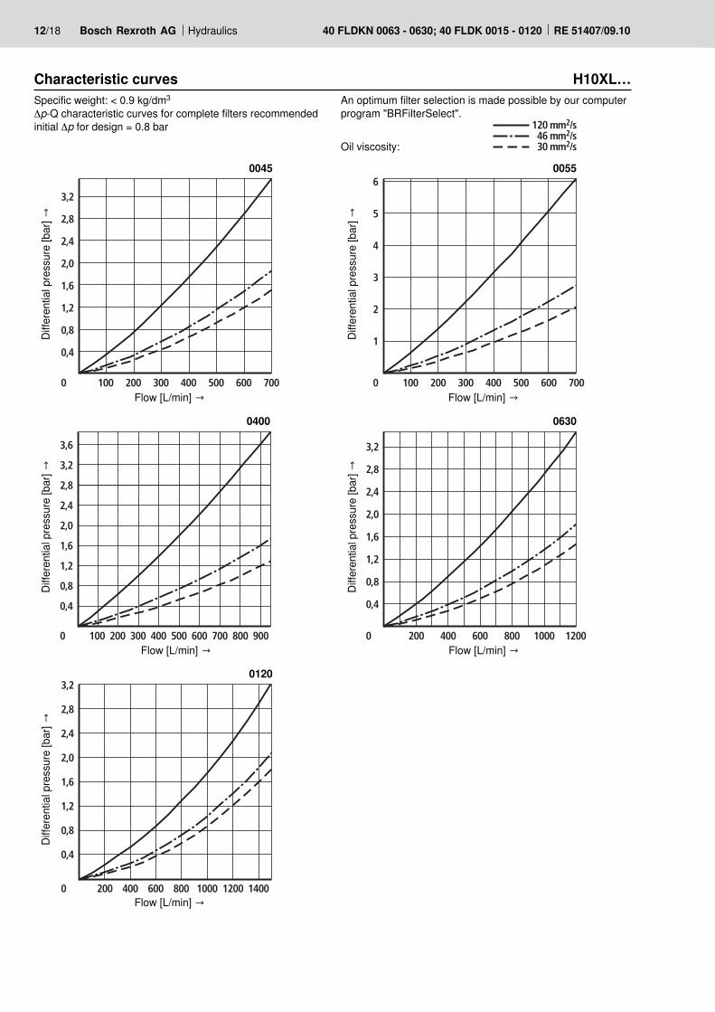
An optimum filter selection is made possible by our computerprogram "BRFilterSelect".
Oil viscosity:
Characteristic curves H10XL…Specific weight: < 0.9 kg/dm3 Δp-Q characteristic curves for complete filters recommended initial Δp for design = 0.8 bar 120 mm2/s
46 mm2/s30 mm2/s
Hydraulics Bosch Rexroth AGRE 51407/09.10 40 FLDKN 0063 - 0630; 40 FLDK 0015 - 0120 13/18
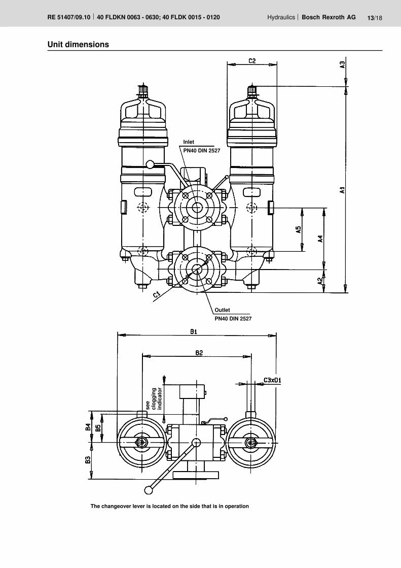
Unit dimensions
InletPN40 DIN 2527
OutletPN40 DIN 2527
The changeover lever is located on the side that is in operation
see
clog
ging
indi
cato
r
14/18 Bosch Rexroth AG Hydraulics 40 FLDKN 0063 - 0630; 40 FLDK 0015 - 0120 RE 51407/09.10
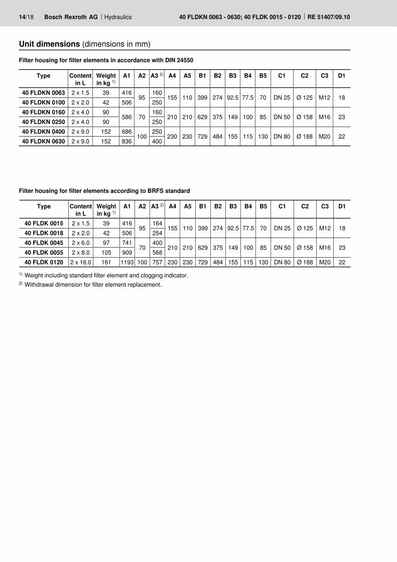
Unit dimensions (dimensions in mm)
Filter housing for filter elements in accordance with DIN 24550
Filter housing for filter elements according to BRFS standard
1) Weight including standard filter element and clogging indicator.2) Withdrawal dimension for filter element replacement.
Type Contentin L
Weightin kg 1)
A1 A2 A3 2) A4 A5 B1 B2 B3 B4 B5 C1 C2 C3 D1
40 FLDKN 0063 2 x 1.5 39 41695
160155 110 399 274 92.5 77.5 70 DN 25 Ø 125 M12 18
40 FLDKN 0100 2 x 2.0 42 506 25040 FLDKN 0160 2 x 4.0 90
586 70160
210 210 629 375 149 100 85 DN 50 Ø 158 M16 2340 FLDKN 0250 2 x 4.0 90 25040 FLDKN 0400 2 x 9.0 152 686
100250
230 230 729 484 155 115 130 DN 80 Ø 188 M20 2240 FLDKN 0630 2 x 9.0 152 836 400
Type Contentin L
Weightin kg 1)
A1 A2 A3 2) A4 A5 B1 B2 B3 B4 B5 C1 C2 C3 D1
40 FLDK 0015 2 x 1.5 39 41695
164155 110 399 274 92.5 77.5 70 DN 25 Ø 125 M12 18
40 FLDK 0018 2 x 2.0 42 506 25440 FLDK 0045 2 x 6.0 97 741
70400
210 210 629 375 149 100 85 DN 50 Ø 158 M16 2340 FLDK 0055 2 x 8.0 105 909 56840 FLDK 0120 2 x 16.0 161 1193 100 757 230 230 729 484 155 115 130 DN 80 Ø 188 M20 22
Hydraulics Bosch Rexroth AGRE 51407/09.10 40 FLDKN 0063 - 0630; 40 FLDK 0015 - 0120 15/18
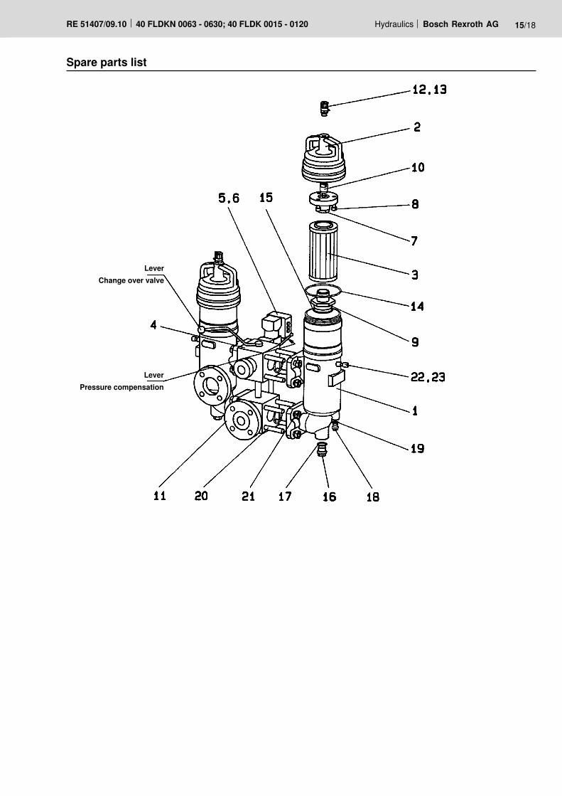
Spare parts list
Lever Change over valve
Lever Pressure compensation
16/18 Bosch Rexroth AG Hydraulics 40 FLDKN 0063 - 0630; 40 FLDK 0015 - 0120 RE 51407/09.10
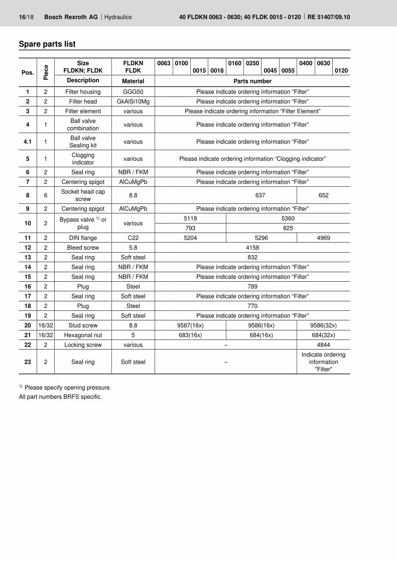
1) Please specify opening pressure.All part numbers BRFS specific.
Spare parts list
Pos.
Piec
e Size FLDKN; FLDK
FLDKN FLDK
0063 01000015 0018
0160 02500045 0055
0400 06300120
Description Material Parts number1 2 Filter housing GGG50 Please indicate ordering information “Filter”2 2 Filter head GkAlSi10Mg Please indicate ordering information “Filter”3 2 Filter element various Please indicate ordering information “Filter Element”
4 1 Ball valvecombination various Please indicate ordering information “Filter”
4.1 1 Ball valveSealing kit various Please indicate ordering information “Filter”
5 1 Cloggingindicator various Please indicate ordering information “Clogging indicator”
6 2 Seal ring NBR / FKM Please indicate ordering information “Filter”7 2 Centering spigot AlCuMgPb Please indicate ordering information “Filter”
8 6 Socket head cap screw 8.8 637 652
9 2 Centering spigot AlCuMgPb Please indicate ordering information “Filter”
10 2 Bypass valve 1) orplug various
5118 5360793 825
11 2 DIN flange C22 5204 5296 496912 2 Bleed screw 5.8 415813 2 Seal ring Soft steel 83214 2 Seal ring NBR / FKM Please indicate ordering information “Filter”15 2 Seal ring NBR / FKM Please indicate ordering information “Filter”16 2 Plug Steel 78917 2 Seal ring Soft steel Please indicate ordering information “Filter”18 2 Plug Steel 77019 2 Seal ring Soft steel Please indicate ordering information “Filter”20 16/32 Stud screw 8.8 9587(16x) 9586(16x) 9586(32x)21 16/32 Hexagonal nut 5 683(16x) 684(16x) 684(32x)22 2 Locking screw various – 4844
23 2 Seal ring Soft steel –Indicate ordering
information "Filter"
Hydraulics Bosch Rexroth AGRE 51407/09.10 40 FLDKN 0063 - 0630; 40 FLDK 0015 - 0120 17/18
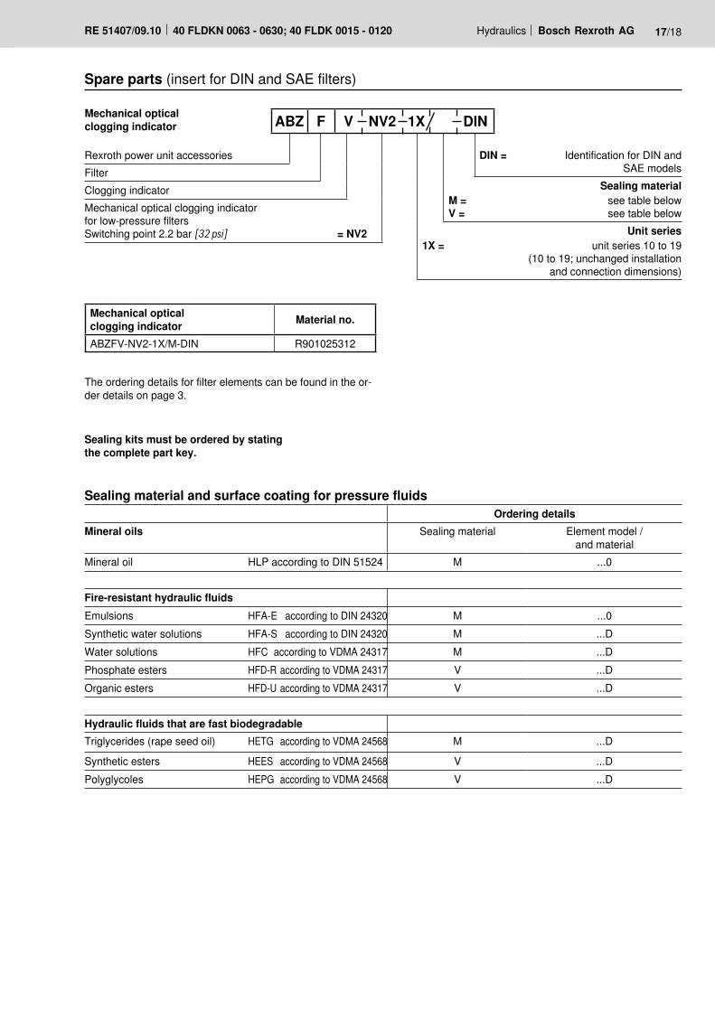
Spare parts (insert for DIN and SAE filters)
DIN = Identification for DIN and SAE models
Sealing materialM = see table belowV = see table below
Unit series1X = unit series 10 to 19
(10 to 19; unchanged installation and connection dimensions)
Mechanical optical clogging indicator ABZ F V NV2 1X DIN
Rexroth power unit accessories
FilterClogging indicatorMechanical optical clogging indicatorfor low-pressure filtersSwitching point 2.2 bar [32 psi] = NV2
Mechanical optical clogging indicator Material no.
ABZFV-NV2-1X/M-DIN R901025312
The ordering details for filter elements can be found in the or-der details on page 3.
Sealing kits must be ordered by stating the complete part key.
Sealing material and surface coating for pressure fluidsOrdering details
Mineral oils Sealing material Element model / and material
Mineral oil HLP according to DIN 51524 M ...0
Fire-resistant hydraulic fluidsEmulsions HFA-E according to DIN 24320 M ...0Synthetic water solutions HFA-S according to DIN 24320 M ...DWater solutions HFC according to VDMA 24317 M ...DPhosphate esters HFD-R according to VDMA 24317 V ...DOrganic esters HFD-U according to VDMA 24317 V ...D
Hydraulic fluids that are fast biodegradableTriglycerides (rape seed oil) HETG according to VDMA 24568 M ...D
Synthetic esters HEES according to VDMA 24568 V ...DPolyglycoles HEPG according to VDMA 24568 V ...D
Bosch Rexroth Filtration Systems GmbHHardtwaldstraße 43, 68775 Ketsch, GermanyPOB 1120, 68768 Ketsch, GermanyPhone +49 (0) 62 02 / 6 03-0Fax +49 (0) 62 02 / 6 03-1 [email protected]
© This document, as well as the data, specifications and other informa-tion set forth in it, are the exclusive property of Bosch Rexroth AG. It may not be reproduced or given to third parties without its consent.The data specified above only serve to describe the product. No state-ments concerning a certain condition or suitability for a certain applica-tion can be derived from our information. The information given does not release the user from the obligation of own judgment and verification. It must be remembered that our products are subject to a natural process of wear and aging.
18/18 Bosch Rexroth AG Hydraulics 40 FLDKN 0063 - 0630; 40 FLDK 0015 - 0120 RE 51407/09.10
Installation, commissioning and maintenanceInstallationVerify operating pressure with name plate information, mount the filter housing (pos. 1) on the fastening device, considering the withdrawal height of the filter element (pos.3). Remove the plugs from the filter inlet and outlet. Connect in-let and outlet at the pipe work free of tension, considering the flow direction (direction arrows).
Warning!Vessel is under pressure!Assemble and disassemble the filter only when system is de-pressurized!Keep the pressure compensation closed if the filter is open (vertical lever position)!Do not operate the change over valve when the filter is opened!Do not replace the clogging indicator and the pressure com-pensation while the filter is under pressure!Functional and safety warranty only applicable when using genuine Rexroth spare parts!Service filter only by trained personnel!
CommissioningSwitch on system pump, open the pressure compensation (horizontal lever position).Bleed filter by opening the bleed screw (pos. 12), close when operating fluid vents. Pressure compensation remains open.
MaintenanceIf at operating temperature, the red indicator pin shows out of the clogging indicator (pos. 5) so far that it contacts the plas-tic cap and/or if the switching process in the electric display is triggered, the filter element is clogged and needs to be re-placed or cleaned respectively.
Filter element replacementActuate the switch-over lever and switch over to the second filter housing. Close the pressure compensation (vertical lever position). Depressurize the decommissioned filter housing. Open bleed screw (pos. 12) by one turn. Open the plugs (pos. 16 +18) and drain contaminated oil.Screw off the filter head (pos. 2).Pull off the filter element (pos. 3) from the centering spigot in the lower filter part by turning it lightly and remove it from the filter housing (pos. 1). Close the plugs (pos. 16 + 18) and bleed screw (pos. 12) again. Check the filter housing for cleanliness and clean it, if necessary. Replace filter elements H...XL and P..., clean the filter ele-ment with material G... . The efficiency of the cleaning pro-cess depends on the type of contamination and the value of the pressure differential. If the pressure differential after replacing the element is more than 50% of the value before replacing the element then the G… filter element also needs to be replaced.Install the cleaned or new filter element into the filter housing and, with light turning movements, plug it onto the centering spigot. Beforehand apply some oil to the filter element seal ring. Dur-ing installation take care to ensure that the filter element is not damaged at the top end of the filter housing.Check the seal ring (pos. 14) in the filter head for damage or wear and replace if necessary. Without any tools, install fil-ter head by rotating it clockwise by hand up to the last thread. Rotate back 1/4 rotation.Open the pressure compensation (horizontal lever position). Bleed filter by opening the bleed screw (pos. 12), close when operating fluid vents.Pressure compensation remains open.
Technical modifications reserved!