
Duality δelta - Amazon Web...
65
Installation and Setup Guide Duality δelta
Transcript of Duality δelta - Amazon Web...

Installation and Setup Guide
Duality δelta

Page b Duality δelta Installation & Setup Guide

Installation and SetupGuide
82BDYG01D
Solid State LogicS O U N D || V I S I O N
Duality δelta

Begbroke, Oxford, England, OX5 1RU • +44 (0)1865 842300
320 West 46th Street, 2nd Floor, New York, NY 10036, USA • +1 (1) 212 315 11113700 Wilshire Blvd, Suite 720, Los Angeles, CA 90010, USA • +1 (1) 213 249 9229
3-55-14 Sendagaya, Shibuya-Ku, Tokyo 151-0051, Japan • +81 (0)3 5474 11447 bis, rue de la Victoire, le Blanc Mesnil, Paris 93150, France • +33 (0)1 48 67 84 85
Visit SSL at URL: http://www.solidstatelogic.com
© Solid State LogicAll Rights reserved under International and Pan-American Copyright Conventions
Duality δelta, AWS δelta, Matrix2, XLogic, X-Rack, X-Desk, Alpha-Link, Delta-Link, Duende, SuperAnalogue
Solid State Logic and SSL are trademarks of Solid State Logic
All other product names and trademarks are the property of their respective owners
No part of this publication may be reproduced in any form orby any means, whether mechanical or electronic, without thewritten permission of Solid State Logic, Oxford, England
Solid State LogicS O U N D || V I S I O N
As research and development is a continual process, Solid State Logic reserves the rightto change the features and specifications described herein without notice or obligation
E&OE
Contents
Section 1 – Introduction 3About This Manual 3Symbols Used 3
Contacting SSL 3
Section 2 – Safety Information 4Definitions 4Installation Instructions 5Voltage Selection and Fusing 5Safety Earth Connection 5Mains Supply and Phases 5Mains Isolation and Over-Current Protection 5
Physical Safety 5Standards Conformance 6FCC Certification 6Instructions for Disposal of WEEE by Users in the EU 6
Section 3 – Preparation 7Services Available From SSL 7Shipment 7Commissioning 7Training 7Factory Warranty 7Extended Warranty 7
Physical Requirements 8Console Control Surface Layout 8Patchbay Options 8Patchbay Connectors – D25 or DL96 8Cable Access and Ducting 9Thermal Considerations 9Service Access 9
System Options 10Technical Requirements 11Sync Source 11Power Connections 11UPS Provision 11Air Conditioning 11Grounding 11Workstation interface 11
Page 1Duality δelta Installation & Setup Guide
Table of Contents
Page 2 Duality δelta Installation & Setup Guide
Table of Contents Section 1
Section 4 – Installation 13Unpacking The Console 13Attaching the legs 13
Removing/fitting the trim 13Console reassembly 15Removing Channel Strips and Panels 15Cable Connections 15Section Assembly 17
Power Connection 19PSU Redundant consoles 19UPS Provision 19
Audio Connections – No Patchbay 21Channel Connections 21Centre Section Connectors 21
Audio Connections – With Patchbay 23Internal Patchbay 23Remote Patchbay 23
Trackball output 25Flash Card 25Red Light/Talkback Connector 25Footswitch Connection 25TFT Monitor Arm Attachment (option) 27
Section 5 – Connecting Your DAW 29Overview 29
Installing the ipMIDI Driver and Logictivity Browser 30ipMIDI Software Installation (For Macintosh) 30ipMIDI Software Installation (For PC) 30
Ethernet Network Setup 31Duality’s IP Address 31Direct Network Connection (Macintosh) 32Direct Network connection (PC) 33Network Connection Using DHCP 34Larger Networks and ipMIDI 35Assigning Duality’s Fixed IP Address 36Network trouble shooting 36
Using Physical MIDI Ports to Connect your DAW 37Enabling ipMIDI on your Duality δelta 39The δ-Ctrl Plug-In 39Setting workstation(s) to communicate via ipMIDI 40Workstation Setup – Pro Tools 41Workstation Setup – Logic Pro X 42
Finding a console on the Duality Remote application 44Enabling the Logictivity features on your console 44
Appendices 45Appendix A – Specifications 46Appendix B – Connector Details 47Appendix C – Connector Pinouts 48Appendix D – Patchbay Layouts 51Appendix E – Console Footprints 56Appendix F – Environmental Specification 61
Section 2 Safety Information
Page 3Duality δelta Installation & Setup Guide
Section 1 – Introduction
About This ManualThe object of this manual is to provide owners and installers of the Solid State Logic (SSL) Duality δelta console withinformation in the following areas:
Section 2 Safety Information – Please read this section as it includes important informationrelating to the electrical supply requirements and to physical safety.
Section 3 Preparation – Provides detail about the console and its optional components and also whatpreparation is necessary relating to the proposed location and any peripheral equipment that may berequired. Some items and services will need to be supplied by the facility.
Section 4 Installation – Provides instructions relating to cabling and connection for the console andits optional items.
Section 5 Connecting Your DAW – Provides step-by-step instructions on how to physicallyconnect your DAW plus the console and workstation configuration settings.
Appendices Specifications, connector pinouts, configuration details and useful guidelines.
The information provided by this manual is relevant to all frame sizes of the Duality console.
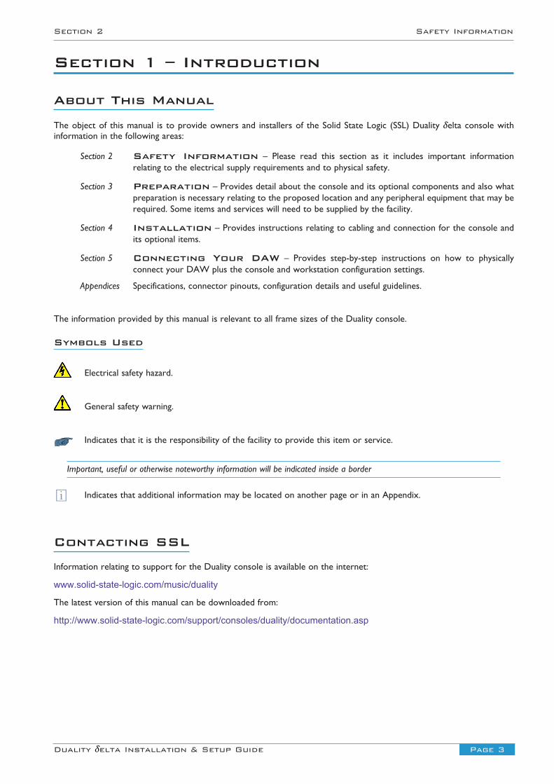
Symbols Used
Electrical safety hazard.
General safety warning.
Indicates that it is the responsibility of the facility to provide this item or service.
Important, useful or otherwise noteworthy information will be indicated inside a border
Indicates that additional information may be located on another page or in an Appendix.
Contacting SSLInformation relating to support for the Duality console is available on the internet:
www.solid-state-logic.com/music/duality
The latest version of this manual can be downloaded from:
http://www.solid-state-logic.com/support/consoles/duality/documentation.asp
i

Safety Information Section 2
Page 4 Duality δelta Installation & Setup Guide
Section 2 – Safety InformationThis section contains definitions and warnings, and practical information to ensure a safe working environment. Please taketime to read this section before undertaking any installation work.
Definitions‘Maintenance’
All maintenance must be carried out by fully trained personnel. Note: It is advisable to observe suitable ESDprecautions when maintenance to any part is undertaken.
‘Non-User Adjustments’
Adjustments or alterations to the equipment may affect the performance such that safety and/or internationalcompliance standards may no longer be met. Any such adjustments must therefore only be carried out by fully trainedpersonnel.
‘Users’
This equipment is designed for use solely by engineers and competent operators skilled in the use of professionalaudio equipment.
‘Environment’
This product is a class A product intended to form an integrated component part of a professional audio recording,mixing, TV, radio broadcast or similar studio wherein it will perform to specification providing that it is installedaccording to professional practice.
Electrical Safety Warning
When installing or servicing any item of SSL equipment with power applied, when cover panels areremoved, HAZARDOUS CONDITIONS CAN EXIST.
These hazards include: • High voltages• High energy stored in capacitors• High currents available from DC power busses• Hot component surfaces
Any metal jewellery (watches, bracelets, neck-chains and rings) that could inadvertently come into contactwith uninsulated parts should always be removed before reaching inside powered equipment.
Section 2 Safety Information
Page 5Duality δelta Installation & Setup Guide
Installation Instructions
Voltage Selection and Fusing
The Duality δelta console uses auto-ranging power supplies so voltage range selection is not necessary. Some 3rd partysub-systems however may have user-selectable voltage inlets. Always confirm that the input mains voltage range is setcorrectly before applying power. Always isolate the mains supply before changing the input range setting.
If it is ever necessary to replace a blown mains fuse, then always use the correct rating and type of replacement. If acorrectly rated fuse continues to blow, then a fault exists and the cause should be investigated or the unit returned to SSLfor repair/replacement as appropriate.
Technical specifications can be found in Appendix A on page 45 of this manual.
Safety Earth Connection
Any mains powered item of SSL equipment that is supplied with a 3-core mains lead (whether connectorised or not)should always have the earth wire connected to the mains supply ground. This is the safety earth and grounds the exposedmetal parts of the racks and cases and should not be removed for any reason.
Mains Supply and Phases
SSL equipment is designed for connection to single-phase supplies with the Neutral conductor at earth potential – categoryTN – and is fitted with a protective fuse in the Live conductor only. It is not designed for use with Phase (Live) and Neutralconnections reversed or where the Neutral conductor is not at earth potential (TT or IT supplies).
All mains powered assemblies must be connected to the same mains phase.
Mains cables will be coded with either of the following colour schemes:
1 or 2LIVE: Brown BlackNEUTRAL: Blue WhiteEARTH: Yellow/Green Green
Mains Isolation and Over-Current Protection
An external disconnect device is required for this equipment; a detachable power cord – as fitted to this equipment – isa suitable disconnect device.
Where a mains plug or appliance coupler is used as the disconnect device, it must remain readily operable.
The power leads must be kept in good condition. If a power cable shows any sign of damage, or if either connector becomesloose, feels warm or appears discoloured then the power lead assembly should be replaced.
An external over-current protection device is required to protect the wiring to this equipment which must be installedaccording to the current wiring regulations; in certain countries this function is supplied by use of a fused plug.
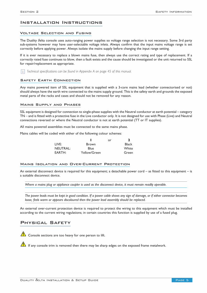
Physical Safety
Console sections are too heavy for one person to lift.
If any console trim is removed then there may be sharp edges on the exposed frame metalwork.
i
Page 6 Duality δelta Installation & Setup Guide
Pre Installation Information Section 3
Standards Conformance
This apparatus fully conforms with the current protection requirements of the European Community Councildirectives on EMC and LVD.
The Duality console complies with the UL safety requirements for the USA and Canada; USA standard
UL1419 and UL Canadian Standard CAN/CSA-C22.2 No. 60950-1-07, 2nd Edition.
Cables supplied with SSL equipment may be fitted with ferrite rings at either end. These are necessary to comply withEuropean CE regulations and should not be removed. If any console metalwork is modified in any way – such as the additionof holes for custom switches etc. – then the CE certification status of the product may be adversely affected.
FCC Certification
The equipment which forms a Duality system has been tested and found to comply with the limits for a Class A digitaldevice, pursuant to part 15 of the FCC Rules. These limits are designed to provide reasonable protection against harmfulinterference when the equipment is operated in a commercial environment.
This equipment generates, uses and can radiate radio frequency energy and, if not installed and used in accordance withthe instruction manual, may cause harmful interference to radio communications. Operation of this equipment in aresidential area is likely to cause harmful interference in which case the user will be required to correct the interferenceat his own expense.
Instructions for Disposal of WEEE by Users in the EU
The symbol shown here, which is on the product or on its packaging, indicates that this product must notbe disposed of with other waste. Instead, it is the user’s responsibility to dispose of their waste equipmentby handing it over to a designated collection point for recycling of waste electrical and electronicequipment. The separate collection and recycling of your waste equipment at the time of disposal will helpto conserve natural resources and ensure that it is recycled in a manner that protects human health andthe environment. For more information about where you can drop off your waste equipment for recycling,please contact your local city office, your household waste disposal service or where you purchased theproduct.
AAAA
Page 7Duality δelta Installation & Setup Guide
Section 3 Pre Installation Information
Section 3 – Preparation
Services Available From SSL
Shipment
All consoles are available ex-works and can be collected from SSL’s headquarters in Begbroke, Oxfordshire, UK.
Packing, crating for airfreight and shipment by specialist carrier can all be arranged at additional cost.
Where delivery is by road and within the EU consoles are normally shipped complete and with legs attached. For all othershipments consoles will be split into 24-channel sections with legs removed; each section will be crated separately. Notethat trim parts are not normally removed for shipment so care must be taken to protect the trim during reassembly.
Commissioning
Duality δelta consoles do not include on-site commissioning by an SSL engineer as standard. Commissioning can berequested at the time of purchase, at additional cost, and is usually expected to take from 2 to 3 days. Consoles above 48channels and those split for shipment or with corner sections may require an additional 1 day of commissioning time.
Before the console is installed all control room building work must be completed and the environment MUST be cleanand free from dust otherwise the warranty will be rendered invalid. Ancillary equipment, such as power distribution andmonitoring loudspeakers, should be installed and working prior to the commissioning date.
We would recommend that commissioning is specified for consoles that are split for shipment. Unless commissioning hasbeen included it will be the responsibility of the facility to reconnect the console sections and to re-attach the legs.
You should contact your local SSL office or agent at least four weeks prior to delivery to allocate a commissioning date.
Training
The commissioning time can be extended to allow for up to two days of standard operator training. This is provided atadditional cost and is subject to engineer availability.
Maintenance training may also be arranged, at additional cost.
Training should be requested at time of order. For all training we recommend that no more than five persons attend eachsession. If the use of an interpreter is necessary the training period may need to be extended (at additional cost). Notethat travel and subsistence expenses are not normally included. Please contact SSL’s Training Department at:[email protected].
Factory Warranty
All new systems include a 13 month warranty which commences on the date of shipment. This warranty includes:
• Technical – phone, fax and e-mail – support via your local distributor or office during normal business hours
• Supply of exchange parts*
• Service engineer visits (note that travel and subsistence costs are not covered by the warranty)
• Maintenance software upgrades
* It is not expected that a visit from an SSL engineer will be necessary in the majority of cases where a replacement part isrequired. Console sub-assemblies are designed to be easily removable to simplify replacement. Please refer to the separateDuality Service Manual, included with the console for additional information.
Extended Warranty
The warranty period may optionally be extended up to a maximum of 5 years. The extended cover available can bespecified as ‘Parts and Labour’ or ‘Parts Only’. In either case the travel and subsistence costs are not included.
Page 8 Duality δelta Installation & Setup Guide
Pre Installation Information Section 3
Physical Requirements
Console Control Surface Layout
• Consoles are available fitted with 24, 48, 72 or 96 input channels. Other channel quantities are not available.
• The centre section can be located to the right of any 24 channel section (ie. not at the left-hand end of the console).
• A 19” section fitted with 12U of racking is available. These sections can be used for rack mounted outboard equipmentand are also used if the console is fitted with an internal patchbay – see ‘Patchbay Options’ below.
• A Producer’s Table section is also available. This assembly is 603mm wide and is fitted with a flat, full-depth table. Cableaccess covers are located at the rear corners of the table.
• Angled corners (12°) can be fitted where the centre section or any 24-channel/rack/table section is joined.
Producer’s tables or patch sections cannot be placed directly to the left of the centre section.
The console is a self-contained system; there are no remote power supplies or I/O racks. The frame is not fitted withcooling fans.
Power, audio and control connections are all made to the rear of the console. A cable tray is fitted along the rear loweredge of the frame to support connecting cables. Console legs are hollow and fitted with a removable rear panel so thatinstallation cables can be concealed inside. Corresponding floor ducting will be necessary to take full advantage of thisfeature. (The 48-channel console is also fitted with a centre leg. This leg is of reduced depth which is insufficient toaccommodate the number of cables from a 24-channel bay).
See Appendix E, page 56, for console footprint drawings.
Patchbay Options
The console may optionally be supplied with a bantam patchbay. Patchbays can be fitted internally to the console or maybe remotely mounted into furniture or racks supplied by the facility.
The number of patchrow sections supplied is dependant upon console size; 24 or 48-channel console will require a single19” section whereas the patch for 72 and 96 channel frames will require 2 off 19” sections.
See Appendix D, page 51, for patchbay layouts.
Patchbays are assembled using individual 1U Bantam patch modules. For internal patchbays these modules will be wireddown to a connector panel mounted at the rear of the patch section legs.
Patchbay Connectors – D25 or DL96
The standard patch internal patch connector panel is fitted with 25-way D-type connectors.
To simplify the integration into a facility with existing cabling, patchbays may optionally be wired out to female DL96connectors mounted at the rear of the patch section.
Each 1U patchrow is a self-contained connectorised unit. The normalling between each pair of upper and lower jacks is setusing normalling links or by internal switches. The normalling on user-option patchrows can therefore be configured asrequired. Information showing how to set the normalling links is printed on the cover of each patchrow unit and in AppendixD on page 51.
See page 22 for additional information relating to patchbays.
i
i
i
Page 9Duality δelta Installation & Setup Guide
Section 3 Pre Installation Information
Cable Access and Ducting
Cable ducting will almost certainly be required between the console and any outboard equipment/patch racks and therecording areas. If a full remote patchbay is being provided then the ducting between the console and the patch racks willneed to be of sufficient size to accommodate the following numbers of cables:
24 channel remote patch will require 36 off 11mm diameter cables48 channel remote patch will require 54 off 11mm diameter cables72 channel remote patch will require 72 off 11mm diameter cables96 channel remote patch will require 90 off 11mm diameter cables
A cable tray is fitted to the rear of the console to support the cable looms is located directly below the connectors. Thetray is provided with holes that coincide with the console leg positions. The console legs are hollow with holes througheach foot so that any leads can be concealed within the console legs. It is recommended that the cables are dropped usingthe nearest leg. Where floor ducting is not available, the lower section of each leg’s rear cover is removable to allow cablesto exit to the rear.
Thermal Considerations
The console is cooled by convection from the front inlet (in the knee panels) to the exit at the top of the rear panels. Itis essential that these ventilation grills are not obstructed in any way.
Particular care must be taken when considering the installation of studio furniture – such as shelving – across the rear ofthe console. Sufficient space must be left for the free flow of air from the rear grills, and also above the heatsink fins.Clearance behind the console must not be less than 50mm and clearance above the console not less than 200mm.
The heatsink fins on the console rear panels can reach temperatures of approximately 30 degrees Celsius aboveambient room temperature.
Service Access
Although access to all electronic assemblies within the frame is from the front of the console, note that each of theconsole’s channel modules is secured by a screw through its rear panel. It is still necessary therefore, to have access tothe rear of the console.

Page 10 Duality δelta Installation & Setup Guide
Pre Installation Information Section 3
System Options
Speaker shelves A flat shelf that fits over the top trim of the console. Can be retrofitted to existing consoleswithout modification.
Additional patchrows 1U connectorised 2 x 48-jack patchrows. Can be specified independently from patchbays.Mating D25–D25 cables are not supplied. DL socket to 3-off 25-way D-type-male adaptorleads are available at extra cost.
DL Connector Panel The internal patchbay option is wired out as standard to a panel fitted with D25 femaleconnectors. This panel can be replaced with one fitted with DL96 female connectors tosimplify the interface to an installation where DL connectors are already in use.
TFT Monitor arm A vertical adjustable arm fitted to the rear of the console to which one or two LCDmonitors may be mounted. Suitable for monitors equipped with the VESA MIS-D 100
mounting. Page 27.
PSU redundancy For critical operations, such as live recording or on-air production a dual power supplysystem can be specified. This option features two independent PSUs per console section,each having an independent mains supply input connector.
Script Tray A 315mm wide Perspex panel which fits over the channel area leaving the faders free. Thetray is fitted with rollers allowing it to be moved sideways across the console.
i
Page 11Duality δelta Installation & Setup Guide
Section 3 Pre Installation Information
Technical Requirements
Sync Source
The Duality δelta console does not require a synchronisation signal.
Power Connections
The console is fitted with auto-sensing power supplies which will function at any voltage from 100 to 240 volts ±10%.
Each console is supplied with one IEC mains power lead for every 24 channel bay (the centre section is powered by thebay to its left). A 48ch console is therefore supplied with two power leads (a 72ch console has three and 96ch with four).The leads provided are 2m in length and wires are colour-coded according to the EC standard.
• A separate power outlet for each 24ch section should be provided beneath the console. Power leads included areunterminated at the supply end to facilitate each user’s preferred connection method.
• Each power outlet provided should be able to be switched and must be protected by a fuse.
• It is recommended that there be provision for all supply outlets to be switched concurrently so that the console canbe switched on or off by a single action.
To reduce the risk of electric shock, plug each power supply cord into separate branch circuits employing separateservice grounds.
Note that consoles fitted with PSU redundancy will require two mains connections for each 24-channel bay.
Refer to Appendix A, page 46, for console power ratings.
UPS Provision
Where either the primary or backup supply of mains power is provided from an uninterruptable source (UPS) theoutput waveform of the UPS equipment must be of the sinusoidal variety. Switched or stepped output waveforms maycause damage to the console power supplies so must not be used.
Air Conditioning
The power dissipated by a 48 channel Duality δelta console is approximately 1,540W (2,200W for 72ch and 2,860 for96ch). When all the studio equipment is taken into consideration, particularly if additional lighting is being installed, thecombined heat output could be sufficient to cause the temperature to rise to uncomfortable levels. It is therefore likelythat air conditioning will be required.
Please refer to the SSL environmental specifications and the additional note relating to humidity levels when planning an air
conditioning system Appendix F, page 61.
Grounding
A standard system should not require any additional grounding over and above that supplied by a correctly installed mainssupply. All console metalwork is permanently bonded to mains earth. A permanent earth connection via the mains inletmust be provided.
A console chassis connection is provided adjacent to the XLR input for channel one at the rear of the console.
All audio connectors have their screen pins connected directly to the chassis at the point of entry to comply with AES/EBUgrounding and EMC standards.
Workstation interface
DAW interfacing is available via standard MIDI 5-pin DIN connectors or over ipMIDI.
A built-in trackball is fitted adjacent to the master fader as a pointing device. Trackball output is via a USB-A socket onthe centre section rear panel.
i
i
Page 12 Duality δelta Installation & Setup Guide
System Installation Section 4
End Trim and Buffer Attachment
Leg Attachment
A
C
C
C
D
D
D
B
Page 13Duality δelta Installation & Setup Guide
Section 4 System Installation
Section 4 – Installation
Unpacking The ConsoleFor deliveries by road transport within the EU it is usual that the console will not be split for shipment and the legs willstill be attached. For other destinations worldwide the console will be split and the legs will be removed – each sectionbeing supplied in a separate wooden crate.
Using a large screwdriver or pry-bar carefully open the crate containing each console section. The crates are not designedto be reusable. With all the crate sides removed there will be sufficient space for a minimum of six people to lift theconsole sections clear of the crate base.
The console is normally shipped with its trim fitted. Do NOT using any trim part as a lifting point. Particularly, do NOT liftthe front of the console using the buffer alone.
Attaching the legs
It is recommended that at least four people are available to perform this operation.
The bolts required to attach the legs are shipped in a separate trim kit box. A 6mm hex-key will be needed to tighten theleg bolts. The bolts screw into a threaded insert inside the main supporting beam. There are four bolts per leg.
Unless trollies or stands are available the safest way to attach the legs is for the console to be rolled onto its back. Ensurethat ample padding is provided – such as blankets or bubble-wrap – to protect the rear panels (the PSU heatsink finsprotrude from the rear of the console and care must be taken not to damage them).
The legs should be positioned so they align with holes in the cable tray – legs are hollow so that cables can be routedinside. Refer to Appendix E for the correct positioning of each console leg.
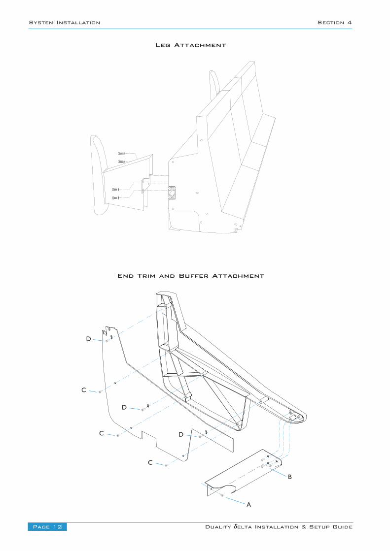
Removing/fitting the trimIf it is necessary to remove the trim sections – to manoeuvre the console or to adjoin existing furniture – then pleaserefer to the following information and the illustration shown on the facing page. Note that it will be necessary to removeaudio channel modules to gain access to some trim fixing screws.
Front Buffer
The front buffer sections are secured by pan-head screws [A] which locate through the buffer into the front beam of theconsole – four screws are used for each 24 channel bay and two screws for the centre section. Where a buffer meets anend trim there are an additional three screws [B] fixed into the trim. Adjacent buffer sections are joined using three screwsand M6 nuts. All the fixings are accessed from beneath the buffer.
End Trim
Each of the end trims is secured in three stages Firstly, three Posi-head screws [C] through the profile (these screws aredirectly accessible). Secondly, three pan-head screws [B] through the front buffer (visible from beneath the buffer). Thirdly,the side trim will now be secured by three more screws [D]. These screws need to be loosened but may not need to beremoved completely as the corresponding holes are widened at the top. Lifting the trim by approximately 20mm shouldallow it to pull free although it may be easier to remove these screws completely.
Top Trim
The top trim for each bay is constructed in two parts: a rear support and a front hinged section. Under most circumstancesaccess for servicing can be gained by simply hinging up the front section. This is a push fit over the meter panels and canbe opened by gently pulling upwards along its front edge. The rear fixed section of the trim is also a push fit over theprofiles but is also screwed to the console rear panels. This section can be removed by undoing the screws and then bypulling upwards – note, this is normally a much firmer fit.
Page 14 Duality δelta Installation & Setup Guide
System Installation Section 4
10
5
0
5
10
20
30
40
50
∞
10
5
0
5
10
20
30
40
50
∞
10
5
0
5
10
20
30
40
50
∞
10
5
0
5
10
20
30
40
50
∞
10
5
0
5
10
20
30
40
50
∞
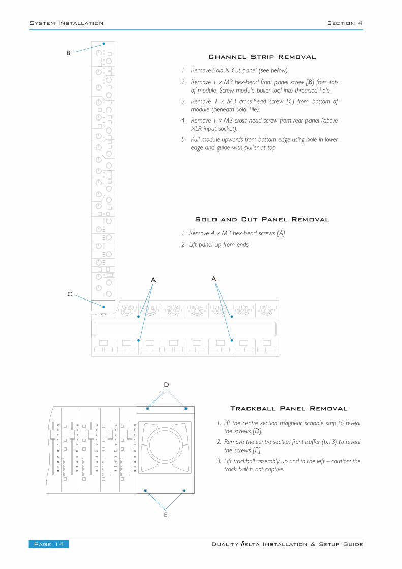
1. Remove 4 x M3 hex-head screws [A]
2. Lift panel up from ends
1. lift the centre section magnetic scribble strip to revealthe screws [D].
2. Remove the centre section front buffer (p.13) to revealthe screws [E].
3. Lift trackball assembly up and to the left – caution: thetrack ball is not captive.
1. Remove Solo & Cut panel (see below).
2. Remove 1 x M3 hex-head front panel screw [B] from topof module. Screw module puller tool into threaded hole.
3. Remove 1 x M3 cross-head screw [C] from bottom ofmodule (beneath Solo Tile).
4. Remove 1 x M3 cross head screw from rear panel (aboveXLR input socket).
5. Pull module upwards from bottom edge using hole in loweredge and guide with puller at top.
Channel Strip Removal
Solo and Cut Panel Removal
Trackball Panel Removal
A
D
E
C
B
A
Page 15Duality δelta Installation & Setup Guide
Section 4 System Installation
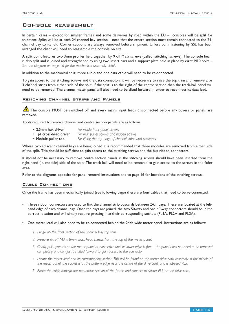
Console reassemblyIn certain cases – except for smaller frames and some deliveries by road within the EU – consoles will be split forshipment. Splits will be at each 24-channel bay section – note that the centre section must remain connected to the 24-channel bay to its left. Corner sections are always removed before shipment. Unless commissioning by SSL has beenarranged the client will need to reassemble the console on site.
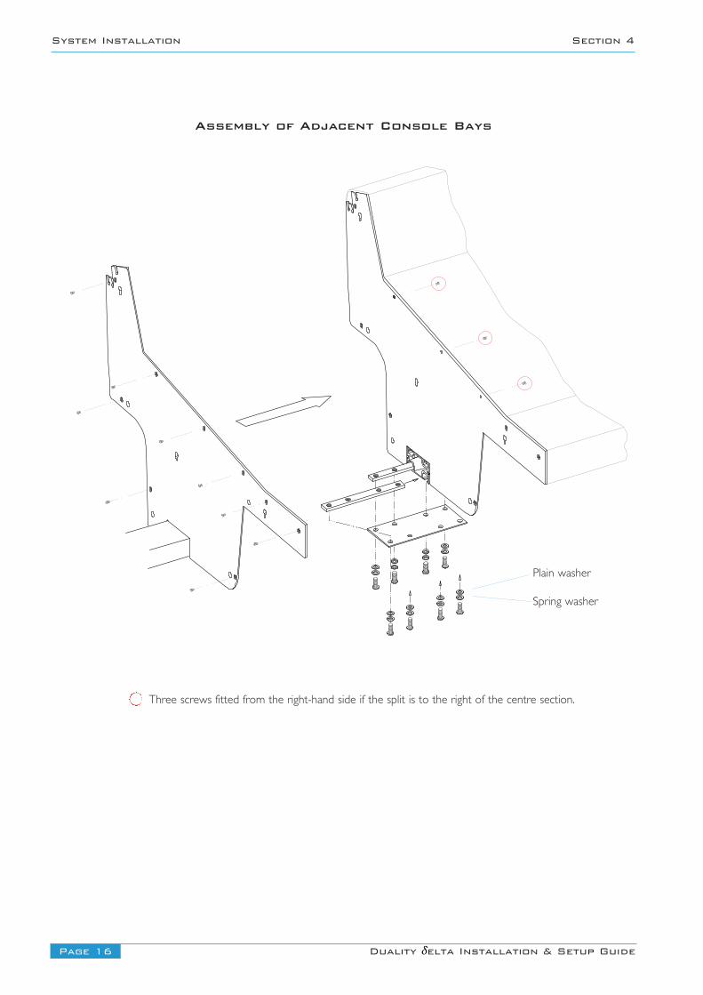
A split point features two 3mm profiles held together by 9 off M3.5 screws (called ‘stitching’ screws). The console beamis also split and is joined and strengthened by using two insert bars and a support plate held in place by eight M10 bolts –See the diagram on page 16 for the mechanical assembly detail.
In addition to the mechanical split, three audio and one data cable will need to be re-connected.
To gain access to the stitching screws and the data connectors it will be necessary to raise the top trim and remove 2 or3 channel strips from either side of the split. If the split is to the right of the centre section then the track-ball panel willneed to be removed. The channel meter panel will also need to be tilted forward in order to reconnect its data lead.
Removing Channel Strips and Panels
The console MUST be switched off and every mains input leads disconnected before any covers or panels areremoved.
Tools required to remove channel and centre section panels are as follows:
• 2.5mm hex driver For visible front panel screws• 1pt cross-head driver For rear panel screws and hidden screws• Module puller tool For lifting the top edge of channel strips and cassettes
Where two adjacent channel bays are being joined it is recommended that three modules are removed from either sideof the split. This should be sufficient to gain access to the stitching screws and the bus ribbon connectors.
It should not be necessary to remove centre section panels as the stitching screws should have been inserted from theright-hand (ie. module) side of the split. The track-ball will need to be removed to gain access to the screws in the faderarea.
Refer to the diagrams opposite for panel removal instructions and to page 16 for locations of the stitching screws.
Cable Connections
Once the frame has been mechanically joined (see following page) there are four cables that need to be re-connected.
• Three ribbon connectors are used to link the channel strip buscards between 24ch bays. These are located at the left-hand edge of each channel bay. Once the bays are joined, the two 50-way and one 40-way connectors should be in thecorrect location and will simply require pressing into their corresponding sockets (PL1A, PL2A and PL3A).
• One meter lead will also need to be re-connected behind the 24ch wide meter panel. Instructions are as follows:
1. Hinge up the front section of the channel bay top trim.
2. Remove six off M3 x 8mm cross head screws from the top of the meter panel.
3. Gently pull upwards on the meter panel at each edge until its lower edge is free – the panel does not need to be removedcompletely and can just be tilted forward to gain access to the connector.
4 Locate the meter lead and its corresponding socket. This will be found on the meter drive card assembly in the middle ofthe meter panel, the socket is at the bottom edge near the centre of the drive card, and is labelled PL3.
5. Route the cable through the penthouse section of the frame and connect to socket PL3 on the drive card.
Page 16 Duality δelta Installation & Setup Guide
System Installation Section 4
Plain washer
Spring washer
Assembly of Adjacent Console Bays
Three screws fitted from the right-hand side if the split is to the right of the centre section.
Page 17Duality δelta Installation & Setup Guide
Section 4 System Installation
Section Assembly
Before commencing mechanical assembly all necessary modules or panels should be removed. The top trim sectionsshould also be hinged open.
Make sure that at least six people are available before attempting to move console sections. Ensure all parts are supportedadequately – a strong stand (such as a stool or trolley) of approximately 420mm high will be extremely useful to supportthe un-supported end of the console whilst the sections are aligned.
Before the sections can be joined, they must be horizontal and at the same height.
Locate the insert parts needed for reassembly of the beam. (These parts will usually be assembled and slid into one of thebeam sections – loosening all eight of the M10 bolts will allow the plate and inserts to slide along to the beam joint).
Position the plate and inserts at the joint so that approximately half of the insert is visible. Hand tighten the bolts.
Align the two console sections so that the beam inserts are in the correct position on the opposing beam. It may benecessary to remove four of the bolts. If particularly awkward then remove all eight bolts and the securing plate.
Carefully push the two console sections together. If the sections are aligned correctly, the inserts should slide into placewith minimal force – they are not a tight fit.
Take particular care that the buscard linking ribbons and the meter cable are not snagged or crushed when positioningthe frame sections.
Fit any remaining M10 bolts and hand-tighten checking that the inserts are still positioned with half in each section. Tightensufficiently so that the joint is secure and the sections will not slide apart. Some adjustment may still be necessary until allscrews are in place.
Although stitching screws can be fitted from either side of the profile they are usually inserted through the left profile toscrew into the right-hand side. The exception will be at the centre-section split where three of the screws are be insertedfrom, the right – thus eliminating the need to remove master section panels.
Before inserting the nine off ‘stitching’ screws check that the profiles are touching all round with no gaps; do not use theM3.5 screws to pull the two sections together
Insert the nine off M3.5 ‘stitching’ screws through the LH profile and loosely fix into the corresponding holes in the RHprofile. Secure each screw by a few turns only until all nine are located.
Gradually tighten the screws a few turns at a time checking that the profile edges are correctly aligned. Only tighten thescrews completely once alignment is correct.
Now fully tighten each of the M10 bolts in the beam plate.
Page 18 Duality δelta Installation & Setup Guide
System Installation Section 4
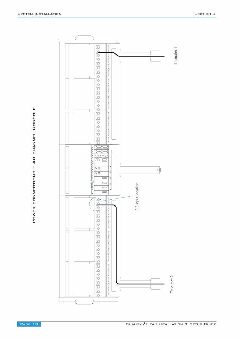
Power connections – 48 channel Console
To outlet 1
IEC input location
To outlet 2
Page 19Duality δelta Installation & Setup Guide
Section 4 System Installation
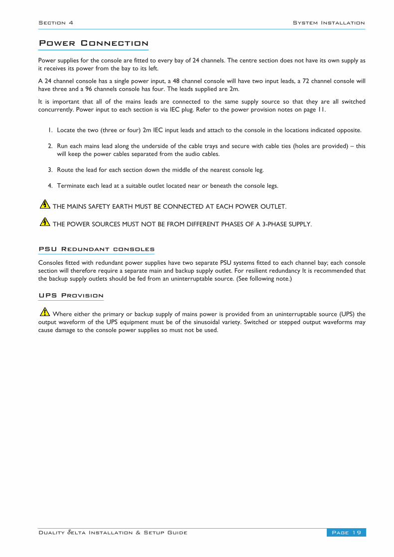
Power ConnectionPower supplies for the console are fitted to every bay of 24 channels. The centre section does not have its own supply asit receives its power from the bay to its left.
A 24 channel console has a single power input, a 48 channel console will have two input leads, a 72 channel console willhave three and a 96 channels console has four. The leads supplied are 2m.
It is important that all of the mains leads are connected to the same supply source so that they are all switchedconcurrently. Power input to each section is via IEC plug. Refer to the power provision notes on page 11.
1. Locate the two (three or four) 2m IEC input leads and attach to the console in the locations indicated opposite.
2. Run each mains lead along the underside of the cable trays and secure with cable ties (holes are provided) – thiswill keep the power cables separated from the audio cables.
3. Route the lead for each section down the middle of the nearest console leg.
4. Terminate each lead at a suitable outlet located near or beneath the console legs.
THE MAINS SAFETY EARTH MUST BE CONNECTED AT EACH POWER OUTLET.
THE POWER SOURCES MUST NOT BE FROM DIFFERENT PHASES OF A 3-PHASE SUPPLY.
PSU Redundant consoles
Consoles fitted with redundant power supplies have two separate PSU systems fitted to each channel bay; each consolesection will therefore require a separate main and backup supply outlet. For resilient redundancy It is recommended thatthe backup supply outlets should be fed from an uninterruptable source. (See following note.)
UPS Provision
Where either the primary or backup supply of mains power is provided from an uninterruptable source (UPS) theoutput waveform of the UPS equipment must be of the sinusoidal variety. Switched or stepped output waveforms maycause damage to the console power supplies so must not be used.
Page 20 Duality δelta Installation & Setup Guide
System Installation Section 4
660X
265
965
965
465
365
265
1
EXT
A3EX
T A4
EXT
A1EX
T A2
Sen
d - I
nser
t - R
tn
Met
er O
utEx
t B 1
-4
Mini
ARMini
AL
Liste
n M
ic In
T/Ba
ck
Mic
In
Liste
nM
ic Ou
t
T/Ba
ck
Mic
Out
Desk
Mic
Ga
in
Ext T
B M
ic G
ain
Osc
Out
Mini
BRM
ini
BL
MO
N B
MO
N A
CUE/
FXBU
S OU
T
658
660X
1
BUS
17-2
4
660X
166
0X1
BUS
9-16
BUS
1-8
ECHO
RET
URNS
1-4
MIX
INSE
RT S
ENDS
MIX
INSE
RT R
ETUR
NSM
AIN
MIX
OUT
PUTS
FB B
L
FB B
R
FB A
L
FB A
R
RED
LIGH
T/TA
LKBA
CK/G
PIO
1 - F
OOTS
WIT
CH -
2
MON
ITOR
INPU
TS
INSE
RT S
ENDS
INSE
RT R
ETUR
NSKE
Y IN
PUTS
CHAN
NEL
OUTP
UTS
MIC
MON
ITOR
INPU
TS
INSE
RT S
ENDS
INSE
RT R
ETUR
NSKE
Y IN
PUTS
CHAN
NEL
OUTP
UTS
MON
ITOR
INPU
TS
INSE
RT S
ENDS
INSE
RT R
ETUR
NSKE
Y IN
PUTS
CHAN
NEL
OUTP
UTS
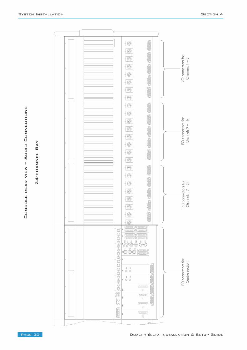
Console rear view – Audio Connections
24-channel Bay
I/O connectors for
Channels 1 – 8
I/O connectors for
Channels 9 – 16
I/O connectors for
Channels 17 – 24
I/O connectors for
Centre section
Page 21Duality δelta Installation & Setup Guide
Section 4 System Installation
Audio Connections – No PatchbayAll audio connections are made at the rear of the console. The majority of line level input and output connections aremade using high quality 25-pin D-type female connectors – some ancillary circuits are accessed using 1/4” jack and XLRs.All Microphone inputs are via 3-pin XLR female connectors.
• All audio circuits are balanced.
• All cable screen pins are connected to the console chassis.
• All XLRs are wired using pin 2 as the non-inverting leg (‘2-hot’).
• The binding posts for the 25-way D-type connectors use the UNC 4-40 thread.
The audio cabling for the channel bays can be routed down the back of the nearest leg; it is possible, with care, to locateall cabling for a 48-channel console within one leg. The centre section cabling can be routed down its own leg or splitbetween the nearest channel bays.
Refer to Appendix C, page 48, for connector pinouts.
Channel Connections
The I/O connectors for each 24-channel bay are arranged into three repeating 8-channel groups. Each group consists offive D25 and 8 XLR female connectors.
The connectors for each group are allocated as follows:
Channel Outputs D25 female Channels direct outputsKey Input D25 female External access to the channel dynamics sidechainInsert Send D25 femaleInsert Return D25 femaleMonitor Input D25 female Line level input to channel/monitor pathChannel Input XLR 3-pin Female (x8) Microphone or 2nd Line level input
Centre Section Connectors
The connectors are allocated as follows:
Ext A 1 [2,3,4] D25 female (x4) Four independent 5.1 inputsExt B D25 female Four independent stereo inputsInsert Send/Return D25 female (x2) 5.1 + Lt/Rt Monitor insert pointMeter Out D25 female Main 5.1 + Solo meter feedsMon A D25 female Main 5.1 + Mini-A loudspeaker feeds*Mon B D25 female Alt 5.1 + Mini-B loudspeaker feeds*Bus 1–8 [9/16, 17/24] D25 female (x3) 24 track outputsCue/FX Bus Out D25 female 2 stereo and 4 mono feedsEcho Returns 1–4 D25 female 2 stereo inputsMix Insert send/return D25 female (x2) 5.1 + stereo mix insert pointMain Mix Outputs D25 female 5.1 + stereo mix out
F/B A and B LR 1/4” balanced jack (x4) Foldback A and B sendsMini A and Mini B XLR 3-pin male (x4) Mini LS A & B sends*Osc out XLR 3-pin male (x4) Oscillator feedListen/TB Mic in XLR 3-pin Female (x2) Listen and Talkback Microphone inputsListen/TB Mic out 1/4” balanced jack (x2) Listen and Talkback Microphone feeds
*Mini A and B feeds are duplicated on D25 and XLR connectors.
i
Page 22 Duality δelta Installation & Setup Guide
System Installation Section 4
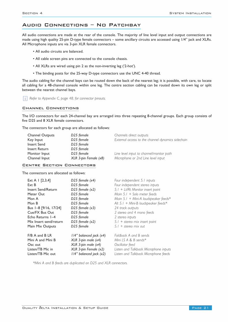
Location of Internal Patch Connector Panel
D25 Connector Panel
Internal Connector Panel(Connectors face towards rear)
48 channel Duality
Patchbay section may be located at either end of the console
DAW O/P 41-48 DAW O/P 33-40 DAW O/P 25-32 DAW O/P 17-24 DAW O/P 9-16 DAW O/P 1-8
DAW I/P 41-48 DAW I/P 33-40 DAW I/P 25-32 DAW I/P 17-24 DAW I/P 9-16 DAW I/P 1-8
MIC I/P 41-48 MIC I/P 33-40 MIC I/P 25-32 MIC I/P 17-24 MIC I/P 9-16 MIC I/P 1-8
ECHO RTNS FX SEND EXT I/P B REC I/P 17-24 REC I/P 9-16 REC I/P 1-8
TALKBACK EXT I/P A4 EXT I/P A3 EXT I/P A2 EXT I/P A1 MIX OUTPUT
USER T41-T48
USER U41-U48
USER V41-V48
USER W41-W48
USER T33-T40
USER U33-U40
USER V33-V40
USER W33-W40
USER T25-T32
USER U25-U32
USER V25-V32
USER W25-W32
USER T17-T24
USER U17-U24
USER V17-V24
USER W17-W24
USER S25-S32
USER R25-R32
USER S17-S24
USER R17-R24
USER S09-S16
USER R09-R16 USER R01-R08
USER S01-S08
USER T09-T16
USER U09-U16
USER V09-V16
USER W09-W16
MON/MINI A
USER T01-T08
USER U01-U08
USER V01-V08
USER W01-W08
MON/MINI B
Page 23Duality δelta Installation & Setup Guide
Section 4 System Installation
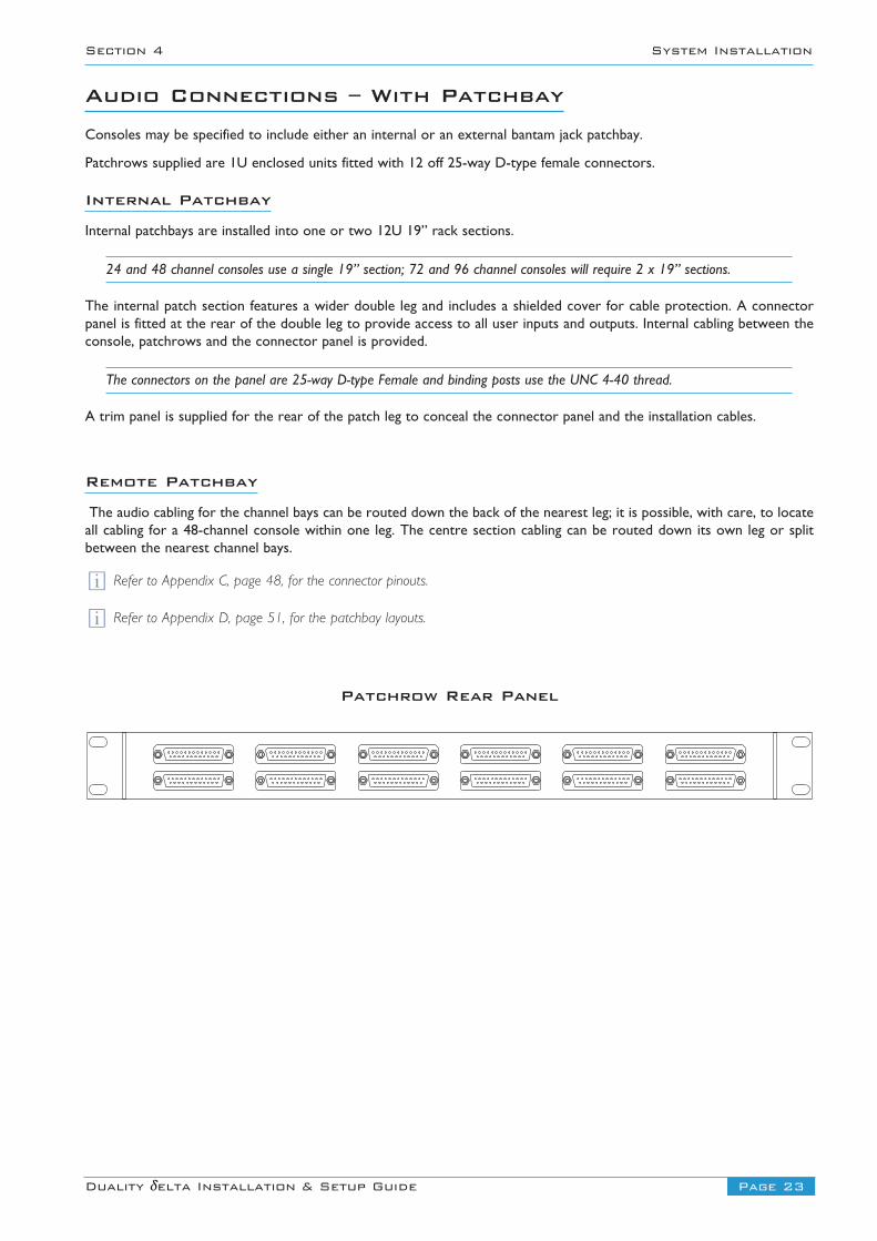
Audio Connections – With PatchbayConsoles may be specified to include either an internal or an external bantam jack patchbay.
Patchrows supplied are 1U enclosed units fitted with 12 off 25-way D-type female connectors.
Internal Patchbay
Internal patchbays are installed into one or two 12U 19” rack sections.
24 and 48 channel consoles use a single 19” section; 72 and 96 channel consoles will require 2 x 19” sections.
The internal patch section features a wider double leg and includes a shielded cover for cable protection. A connectorpanel is fitted at the rear of the double leg to provide access to all user inputs and outputs. Internal cabling between theconsole, patchrows and the connector panel is provided.
The connectors on the panel are 25-way D-type Female and binding posts use the UNC 4-40 thread.
A trim panel is supplied for the rear of the patch leg to conceal the connector panel and the installation cables.
Remote Patchbay
The audio cabling for the channel bays can be routed down the back of the nearest leg; it is possible, with care, to locateall cabling for a 48-channel console within one leg. The centre section cabling can be routed down its own leg or splitbetween the nearest channel bays.
Refer to Appendix C, page 48, for the connector pinouts.
Refer to Appendix D, page 51, for the patchbay layouts.
ii
Patchrow Rear Panel
Page 24 Duality δelta Installation & Setup Guide
System Installation Section 4
GAIN
MIC
ARMIN
I
ALMIN
I
EXT
OUT
MIC
T/B
OUT
MIC
LIST
INMIC
LIST
INMIC
T/B
DESK
23
123
123
123
1
23
123
1 23
1
IN1
OUT1
IN2
OUT2
IN3
OUT3
IN4
OUT4
IN5
OUT5
IN6
OUT6
IN7
OUT7
IN8
OUT8
SEND
- IN
SERT
- RT
N
MET
EROU
TEX
T B
1-4
EXT
A1EX
T A2
EXT
A3EX
T A4
BRMIN
I
BLMIN
I
MON
AM
ON B
FB A
L
CUE/
FXBU
S OU
T
ECHO
RET
URNS
1–4
RED
LIGH
T / T
ALKB
ACK
FB A
R
FB B
L
FB B
R
MIX
INSE
RT S
ENDS
MIX
INSE
RT R
ETUR
NSM
AIN
MIX
OUT
PUTS
BUS
17–2
4BU
S9–
16BU
S1–
8
1 - F
OOTS
WIT
CH -
2TR
ACKB
ALL
SERI
AL 1
SERI
AL 2
NETW
ORK
OUT
OSC
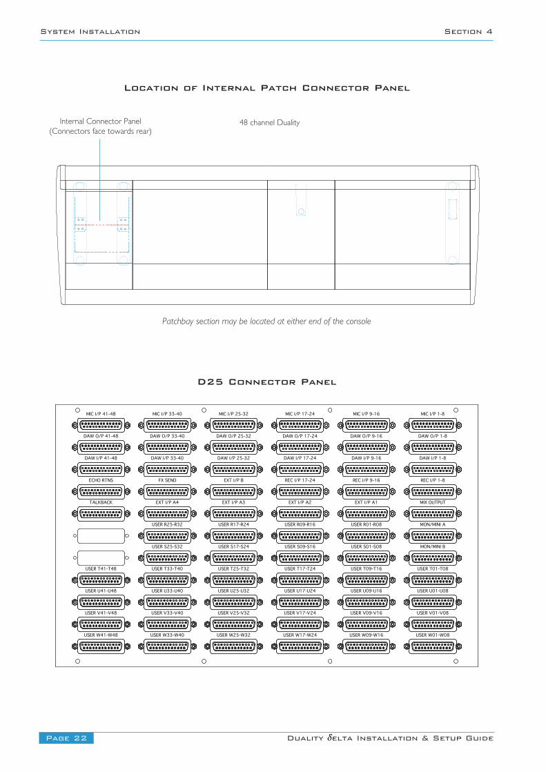
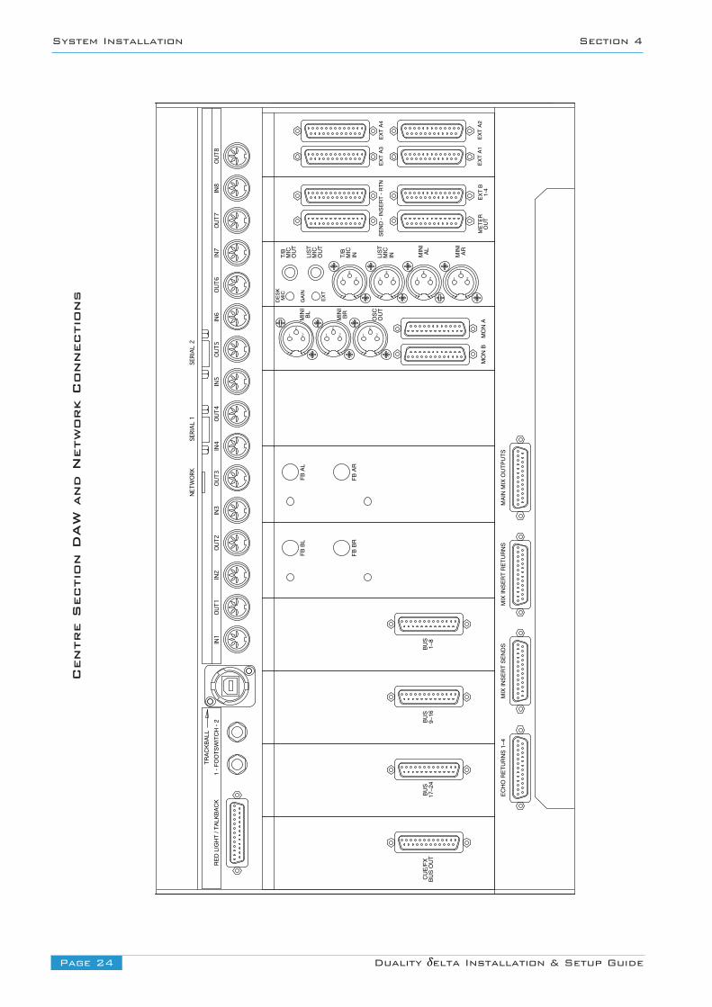
Centre Section DAW and Network Connections
Trackball outputThe inbuilt trackball is a standard USB device. Its signal output is available on the USB-A connector on the rear of thecentre section. This should be connected to the workstation computer. The trackball is the Kensington Expert Mouse andthe Kensington driver disk is supplied with the console.
Flash CardAn SD flash card is fitted vertically at the rear of the console adjacent to the two serial data connectors. This is used forstoring project information and should not be removed during normal operation.
Red Light/Talkback ConnectorThe D25 fitted to the rear panel provides the connection for the red light switch contacts. It also provides input andoutput signals for monitoring, talkback and signalling functions. Switch functions are activated by connecting their inputsdown to 0V.
NOTE. The contacts for the Red Light output are via a DIL relay and are rated as follows: 30Vdc, 25Vac, 100mA max. Donot use the Red Light contacts to directly switch capacitive or reactive loads; always use an external relay with a suitablecontact rating.
Refer to Appendix C, page 48, for the connector pinouts.
Footswitch ConnectionIn addition to the logic functions provided in the above red light/talkback connector, two additional assignable inputs areavailable on footswitch 1/4” jacks.
Mono jacks are used – signals are activated by connecting the two jack contacts together.
i
Page 25Duality δelta Installation & Setup Guide
Section 4 System Installation
Page 26 Duality δelta Installation & Setup Guide
System Installation Section 4
Beam Insert (x2)
Support bracket
Washer (x4)Spring washer (x4)
M10 bolt (x4)
Arm mounting post
Crinkle washer
M12 bolt
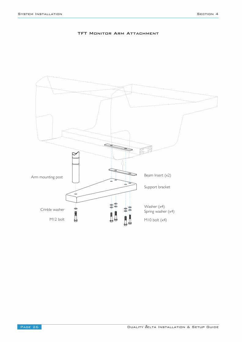
TFT Monitor Arm Attachment

TFT Monitor Arm Attachment (option)A single or double TFT monitor mounting arm is available as an option. The arm is compatible with all VESA compliantflat screen monitors.
The arm is attached to the console using a support plate which is bolted to two inserts in the main console beam. Thediagram opposite details how the arm is attached to the console beam.
Arm Specifications
The standard articulated arm has a maximum weight capacity of 8.5Kg (18.7lb), with a maximum extension (centre ofmounting pole to rear of screen) of 460mm.
Articulated arms with increased load capacities of 12Kg (maximum extension of 425mm) or 24Kg (maximum extension of437mm) are available at additional cost. Contact SSL’s Project Engineering department for further details.
Monitor arms are supported on a 700mm pole which will have a small degree of flex when supporting a large load. It isrecommended that when using the heavy duty monitor arms, only a single arm is used per mounting post
Page 27Duality δelta Installation & Setup Guide
Section 4 System Installation

Blank page
Page 28 Duality δelta Installation & Setup Guide
System Installation Section 4
Page 29Duality δelta Installation & Setup Guide
Section 5 Setting Up Your DAW
Section 5 – Connecting Your DAW
Overview
Duality δelta communicates with a DAW using a MIDI interface. The MIDI interface allows Duality δelta to be used witha wide variety of DAW applications on a number of different platforms.
The MIDI connection can be made either by connecting physical cables to a multiport MIDI interface, or via an Ethernetconnection after installing an ipMIDI driver onto the workstation computer. The ipMIDI driver enables your workstation tosend and receive MIDI control data via a network. Using Ethernet ensures the fastest possible communication between yourworkstation computer and Duality.
Duality DAW control uses either the Mackie Control Universal (MCU) or the ‘HUI’ compatible protocols so any DAWprogram that can be configured to use multiple HUI or MCU devices is able to access the full power of the Duality δelta.Please refer to your DAW manual for details on how to configure the DAW application for Duality δelta under Mackieor HUI control.
This section deals with the Ethernet connection method – which allows two DAW control layers to be configured. If thephysical MIDI cable connection method is being used (using a multi-port MIDI interface), then only one DAW Control layercan be configured. The physical MIDI ports are located on the rear of the console; this connection method is described onpage 37.
Before the console can successfully communicate with the DAW over Ethernet the following steps must all be completed:
1 The Ethernet connection must work and be defined correctly:
• Install the ipMIDI driver• Create the Ethernet network – either directly or via a LAN (switch or managed hub)
2 The Duality console ‘Setup’ preferences must be defined correctly:
• Enable ipMIDI on the Duality console• Select the DAW layer
3 The Pro Tools settings must be defined correctly:
• Set up the MIDI controller configuration• Set up MTC and MMC• Logic Pro settings• Find the console using the Duality Remote application
To help troubleshoot any problems, some notes are provided on page 36.
Page 30 Duality δelta Installation & Setup Guide
Setting Up Your DAW Section 5
Installing the ipMIDI Driver and Logictivity BrowserBefore you can use an Ethernet connection (either directly or via a network) a third party ipMIDI software driver mustbe installed onto the DAW computer.
Download on to your workstation computer either the DualityDelta_Mac_Support.dmg disk image (Macintosh) or theDualityDelta_Win_Support.zip file (Windows). These contain the Duality Remote and ipMIDI applications and the latestversion of the installation instructions:
http://www.solidstatelogic.com/support/consoles/duality/downloads.aspSystem requirements for your workstation computer:
• Duality Remote is a Java application. It will run under Java Version 5 or higher. • ipMIDI is compatible with Windows 2000 (max 9 MIDI ports), XP, Vista , 7 and Macintosh OSX 10.4 and above.
ipMIDI Software Installation (For Macintosh)
Mount the DualityDelta_Mac_Support.dmg disk image and open it.
Duality Remote — Drag the enclosed Duality Remote application to the Applications folder, then to the Dock orany other convenient location.
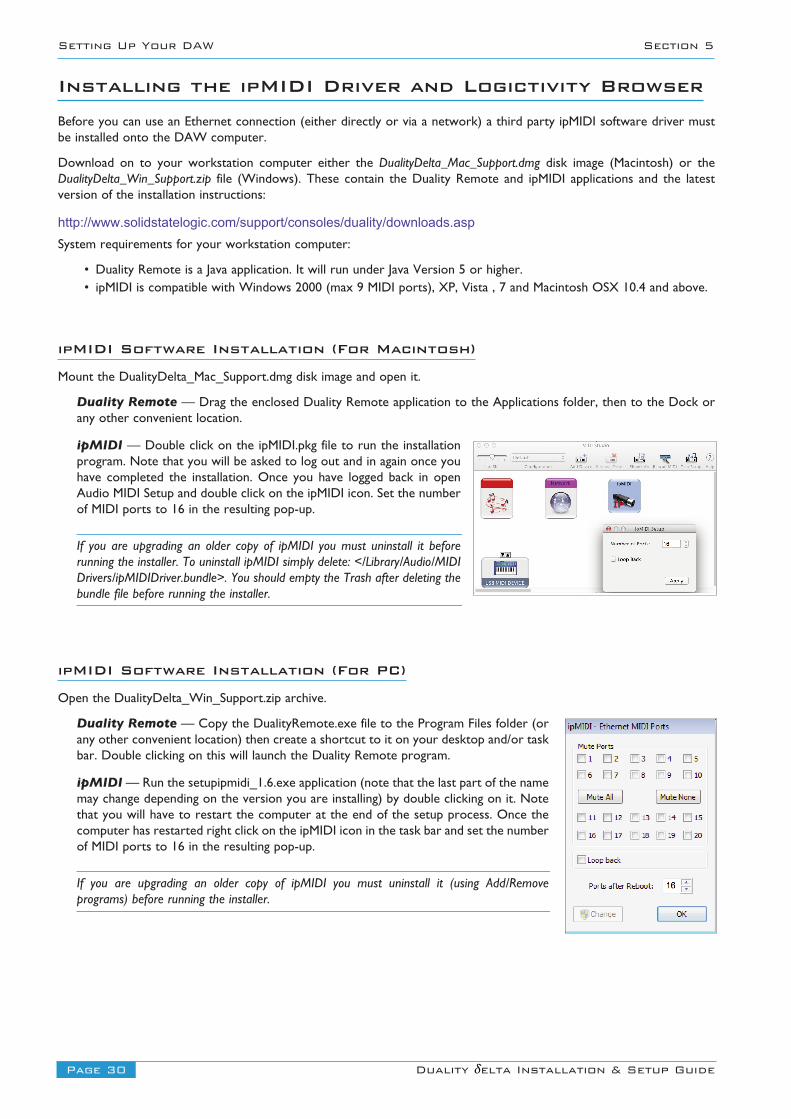
ipMIDI — Double click on the ipMIDI.pkg file to run the installationprogram. Note that you will be asked to log out and in again once youhave completed the installation. Once you have logged back in openAudio MIDI Setup and double click on the ipMIDI icon. Set the numberof MIDI ports to 16 in the resulting pop-up.
If you are upgrading an older copy of ipMIDI you must uninstall it beforerunning the installer. To uninstall ipMIDI simply delete: </Library/Audio/MIDIDrivers/ipMIDIDriver.bundle>. You should empty the Trash after deleting thebundle file before running the installer.
ipMIDI Software Installation (For PC)
Open the DualityDelta_Win_Support.zip archive.
Duality Remote — Copy the DualityRemote.exe file to the Program Files folder (orany other convenient location) then create a shortcut to it on your desktop and/or taskbar. Double clicking on this will launch the Duality Remote program.
ipMIDI — Run the setupipmidi_1.6.exe application (note that the last part of the namemay change depending on the version you are installing) by double clicking on it. Notethat you will have to restart the computer at the end of the setup process. Once thecomputer has restarted right click on the ipMIDI icon in the task bar and set the numberof MIDI ports to 16 in the resulting pop-up.
If you are upgrading an older copy of ipMIDI you must uninstall it (using Add/Removeprograms) before running the installer.
Page 31Duality δelta Installation & Setup Guide
Section 5 Setting Up Your DAW
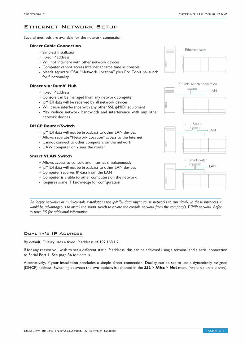
Ethernet Network SetupSeveral methods are available for the network connection:
Direct Cable Connection
+ Simplest installation+ Fixed IP address+ Will not interfere with other network devices- Computer cannot access Internet at same time as console- Needs separate OSX “Network Location” plus Pro Tools re-launchfor functionality
Direct via ‘Dumb’ Hub
+ Fixed IP address+ Console can be managed from any network computer- ipMIDI data will be received by all network devices- Will cause interference with any other SSL ipMIDI equipment- May reduce network bandwidth and interference with any othernetwork devices
DHCP Router/Switch
+ ipMIDI data will not be broadcast to other LAN devices+ Allows separate “Network Location” access to the Internet- Cannot connect to other computers on the network- DAW computer only sees the router
Smart VLAN Switch
+ Allows access to console and Internet simultaneously+ ipMIDI data will not be broadcast to other LAN devices+ Computer receives IP data from the LAN+ Computer is visible to other computers on the network- Requires some IT knowledge for configuration
On larger networks or multi-console installations the ipMIDI data might cause networks to run slowly. In these instances itwould be advantageous to install the smart switch to isolate the console network from the company’s TCP/IP network. Referto page 35 for additional information.
Duality’s IP Address
By default, Duality uses a fixed IP address of 192.168.1.2.
If for any reason you wish to set a different static IP address, this can be achieved using a terminal and a serial connectionto Serial Port 1. See page 36 for details.
Alternatively, if your installation precludes a simple direct connection, Duality can be set to use a dynamically assigned(DHCP) address. Switching between the two options is achieved in the SSL > Misc > Net menu (requires console restart).
LAN
Ethernet cable
‘Dumb’ switch connection
Router
Smart switch
LAN
LAN
Page 32 Duality δelta Installation & Setup Guide
Setting Up Your DAW Section 5
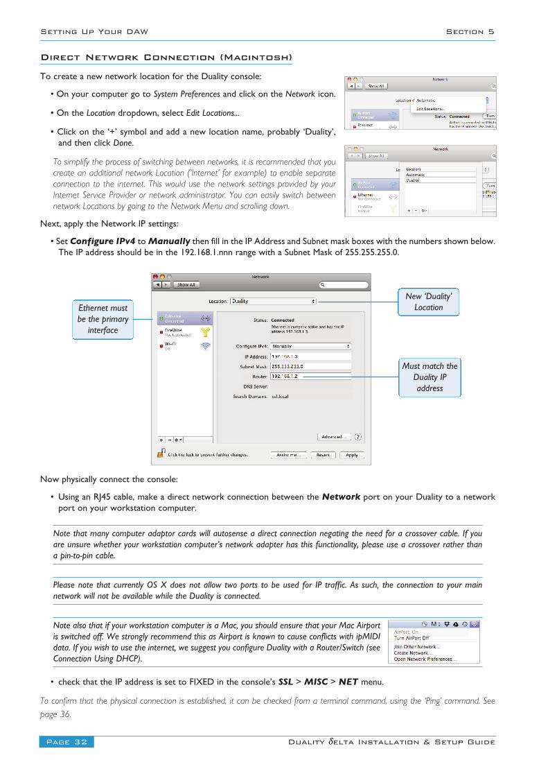
Direct Network Connection (Macintosh)
To create a new network location for the Duality console:
• On your computer go to System Preferences and click on the Network icon.
• On the Location dropdown, select Edit Locations...
• Click on the ‘+’ symbol and add a new location name, probably ‘Duality’,and then click Done.
To simplify the process of switching between networks, it is recommended that youcreate an additional network Location (‘Internet’ for example) to enable separateconnection to the internet. This would use the network settings provided by yourInternet Service Provider or network administrator. You can easily switch betweennetwork Locations by going to the Network Menu and scrolling down.
Next, apply the Network IP settings:
• Set Configure IPv4 to Manually then fill in the IP Address and Subnet mask boxes with the numbers shown below.The IP address should be in the 192.168.1.nnn range with a Subnet Mask of 255.255.255.0.
Now physically connect the console:
• Using an RJ45 cable, make a direct network connection between the Network port on your Duality to a networkport on your workstation computer.
Note that many computer adaptor cards will autosense a direct connection negating the need for a crossover cable. If youare unsure whether your workstation computer’s network adapter has this functionality, please use a crossover rather thana pin-to-pin cable.
Please note that currently OS X does not allow two ports to be used for IP traffic. As such, the connection to your mainnetwork will not be available while the Duality is connected.
Note also that if your workstation computer is a Mac, you should ensure that your Mac Airportis switched off. We strongly recommend this as Airport is known to cause conflicts with ipMIDIdata. If you wish to use the internet, we suggest you configure Duality with a Router/Switch (seeConnection Using DHCP).
• check that the IP address is set to FIXED in the console’s SSL > MISC > NET menu.
To confirm that the physical connection is established, it can be checked from a terminal command, using the ‘Ping’ command. See
page 36.
New ‘Duality’Location
Must match theDuality IPaddress
Ethernet mustbe the primaryinterface
Page 33Duality δelta Installation & Setup Guide
Section 5 Setting Up Your DAW
Direct Network connection (PC)
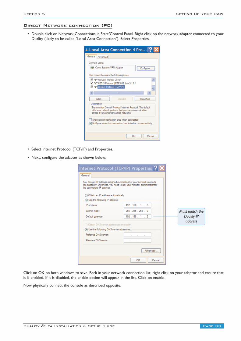
• Double click on Network Connections in Start/Control Panel. Right click on the network adapter connected to yourDuality (likely to be called "Local Area Connection"). Select Properties.
• Select Internet Protocol (TCP/IP) and Properties.
• Next, configure the adapter as shown below:
Click on OK on both windows to save. Back in your network connection list, right click on your adaptor and ensure thatit is enabled. If it is disabled, the enable option will appear in the list. Click on enable.
Now physically connect the console as described opposite.
Must match theDuality IPaddress
Page 34 Duality δelta Installation & Setup Guide
Setting Up Your DAW Section 5
Network Connection Using DHCP
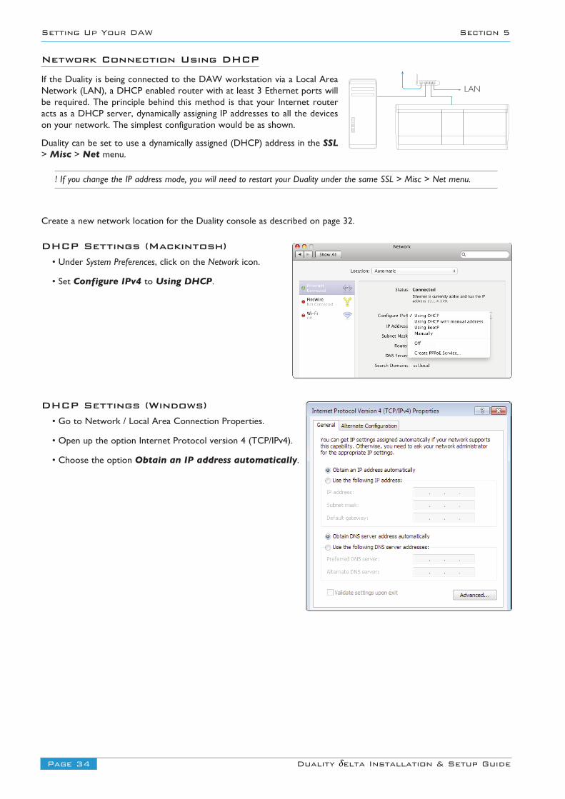
If the Duality is being connected to the DAW workstation via a Local AreaNetwork (LAN), a DHCP enabled router with at least 3 Ethernet ports willbe required. The principle behind this method is that your Internet routeracts as a DHCP server, dynamically assigning IP addresses to all the deviceson your network. The simplest configuration would be as shown.
Duality can be set to use a dynamically assigned (DHCP) address in the SSL> Misc > Net menu.
! If you change the IP address mode, you will need to restart your Duality under the same SSL > Misc > Net menu.
Create a new network location for the Duality console as described on page 32.
DHCP Settings (Mackintosh)• Under System Preferences, click on the Network icon.
• Set Configure IPv4 to Using DHCP.
DHCP Settings (Windows)• Go to Network / Local Area Connection Properties.
• Open up the option Internet Protocol version 4 (TCP/IPv4).
• Choose the option Obtain an IP address automatically.
LAN
Page 35Duality δelta Installation & Setup Guide
Section 5 Setting Up Your DAW
Larger Networks and ipMIDI
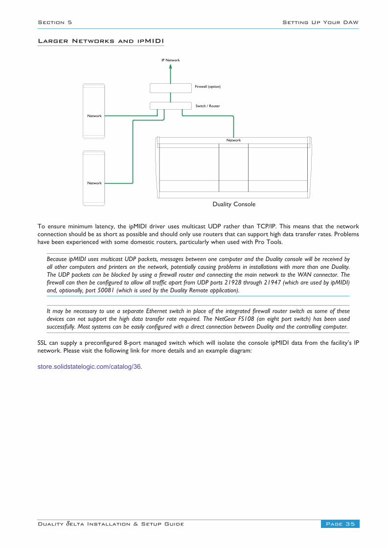
To ensure minimum latency, the ipMIDI driver uses multicast UDP rather than TCP/IP. This means that the networkconnection should be as short as possible and should only use routers that can support high data transfer rates. Problemshave been experienced with some domestic routers, particularly when used with Pro Tools.
Because ipMIDI uses multicast UDP packets, messages between one computer and the Duality console will be received byall other computers and printers on the network, potentially causing problems in installations with more than one Duality.The UDP packets can be blocked by using a firewall router and connecting the main network to the WAN connector. Thefirewall can then be configured to allow all traffic apart from UDP ports 21928 through 21947 (which are used by ipMIDI)and, optionally, port 50081 (which is used by the Duality Remote application).
It may be necessary to use a separate Ethernet switch in place of the integrated firewall router switch as some of thesedevices can not support the high data transfer rate required. The NetGear FS108 (an eight port switch) has been usedsuccessfully. Most systems can be easily configured with a direct connection between Duality and the controlling computer.
SSL can supply a preconfigured 8-port managed switch which will isolate the console ipMIDI data from the facility’s IPnetwork. Please visit the following link for more details and an example diagram:
store.solidstatelogic.com/catalog/36.
IP Network
Switch / Router
Network
Duality SE Console
Network
Network
Firewall (option)
Duality Console
Page 36 Duality δelta Installation & Setup Guide
Setting Up Your DAW Section 5
Assigning Duality’s Fixed IP Address
An alternative fixed IP address can be set using the console’s diagnostic port. You will need a PC or Mac running terminalemulator software. Connect your computer’s serial port to Serial Port 2 on the rear of the console using a 9 way ‘D’ typeextension cable. The pin-out for Serial Port 2 is shown on page 50.
Set the terminal configuration as follows:
Baud rate 19200, 8 data bits, No parity, No start bit, 1 stop bit, Flow control Xon/Xoff
Press the ‘Return’ key (<CR>) and the terminal window should echo a ‘>’ if communication is established.
To fix the IP address type the following:
ip <CR>
setip nnn nnn nnn nnn <CR> Where ‘nnn...’ is the IP address, 192.168.1.2
setmask nnn nnn nnn nnn <CR> Where ‘nnn...’ is the subnet mask 192.168.1.1. Note that this should match otherdevices local to the console.
setgate nnn nnn nnn nnn <CR> Where ‘nnn...’ is the gateway address e.g. ‘10 1 1 1’
Network trouble shooting
Most Ethernet adaptor cards have two leds associated with each port. The first indicates that the link is connected andthe second indicates network traffic. Please note that some Macintosh computers do not have external leds to indicatestatus. Instead the link status is shown in the System Preferences/Network menu.
On your host workstation computer, confirm that the link led is permanently illuminated. If it is not permanentlyilluminated, it suggests you have a cabling error. In this instance please check the following:
• The RJ45 network connector on the console and on your workstation are fully inserted.
• If you are using a pin-pin cable to make a direct connection between your console and workstation, try replacing itwith a crossover cable
• Try replacing the network cable
• If you are not using a direct connection between your console and workstation using the default fixed IP address onthe console, please try this simple configuration to rule out issues with external routers and network switches. If thelink led is illuminated, the next step is to confirm that the activity led is illuminating periodically to show networktraffic. If it does not illuminate periodically check the following:
• If your workstation is not connected directly to your console using a crossover RJ45 cable and fixed IP addressing,follow the installation instructions to configure this simple network configuration to rule out issues with any externalrouters or network switches.
• Using the fixed default IP address on the console, check that the workstation has basic communications using ‘ping’.
Under Windows – Select: ‘Run’ under the ‘Start’ menu. In the resulting window enter ‘cmd’ to launch the command prompt.In the command prompt window enter ‘ping 192.168.1.2’
On OSX: Open a Finder window, select Applications, then Utilities, and double-click on Terminal. In the terminal windowenter ‘ping –c4 192.168.1.2’
In both cases your host computer will try to establish communications with your console. In the resultant terminal text,check that the console responded to every message sent by your workstation.
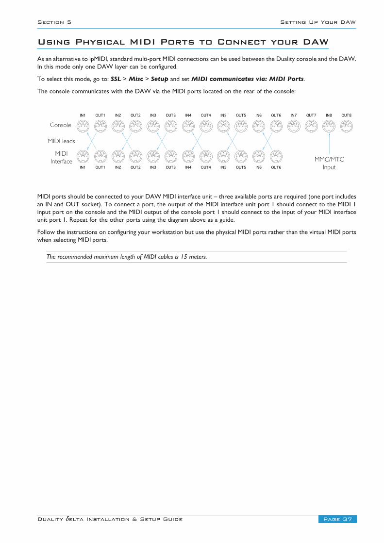
Using Physical MIDI Ports to Connect your DAWAs an alternative to ipMIDI, standard multi-port MIDI connections can be used between the Duality console and the DAW.In this mode only one DAW layer can be configured.
To select this mode, go to: SSL > Misc > Setup and set MIDI communicates via: MIDI Ports.
The console communicates with the DAW via the MIDI ports located on the rear of the console:
MIDI ports should be connected to your DAW MIDI interface unit – three available ports are required (one port includesan IN and OUT socket). To connect a port, the output of the MIDI interface unit port 1 should connect to the MIDI 1input port on the console and the MIDI output of the console port 1 should connect to the input of your MIDI interfaceunit port 1. Repeat for the other ports using the diagram above as a guide.
Follow the instructions on configuring your workstation but use the physical MIDI ports rather than the virtual MIDI portswhen selecting MIDI ports.
The recommended maximum length of MIDI cables is 15 meters.
Page 37Duality δelta Installation & Setup Guide
Section 5 Setting Up Your DAW
IN1 OUT1 IN2 OUT2 IN3 OUT3 IN4 OUT4 IN5 OUT5 IN6 OUT6 IN7 OUT7 IN8 OUT8
IN1 OUT1 IN2 OUT2 IN3 OUT3 IN4 OUT4 IN5 OUT5 IN6 OUT6
Console
MIDI leads
MIDIInterface MMC/MTC
Input

Blank page
Page 38 Duality δelta Installation & Setup Guide
Setting Up Your DAW Section 5
Page 39Duality δelta Installation & Setup Guide
Section 5 Setting Up Your DAW
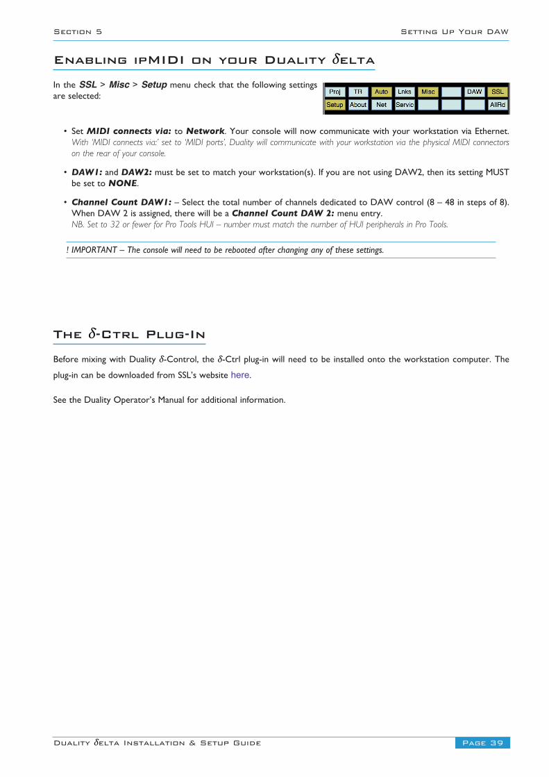
Enabling ipMIDI on your Duality δeltaIn the SSL > Misc > Setup menu check that the following settingsare selected:
• Set MIDI connects via: to Network. Your console will now communicate with your workstation via Ethernet.With ‘MIDI connects via:’ set to ‘MIDI ports’, Duality will communicate with your workstation via the physical MIDI connectorson the rear of your console.
• DAW1: and DAW2: must be set to match your workstation(s). If you are not using DAW2, then its setting MUSTbe set to NONE.
• Channel Count DAW1: – Select the total number of channels dedicated to DAW control (8 – 48 in steps of 8).When DAW 2 is assigned, there will be a Channel Count DAW 2: menu entry.NB. Set to 32 or fewer for Pro Tools HUI – number must match the number of HUI peripherals in Pro Tools.
! IMPORTANT – The console will need to be rebooted after changing any of these settings.
The δ-Ctrl Plug-InBefore mixing with Duality δ-Control, the δ-Ctrl plug-in will need to be installed onto the workstation computer. The
plug-in can be downloaded from SSL’s website here.
See the Duality Operator’s Manual for additional information.
Page 40 Duality δelta Installation & Setup Guide
Setting Up Your DAW Section 5
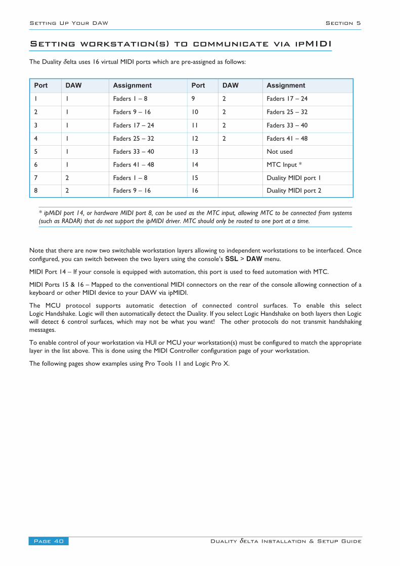
Setting workstation(s) to communicate via ipMIDIThe Duality δelta uses 16 virtual MIDI ports which are pre-assigned as follows:
* ipMiDI port 14, or hardware MIDI port 8, can be used as the MTC input, allowing MTC to be connected from systems(such as RADAR) that do not support the ipMIDI driver. MTC should only be routed to one port at a time.
Note that there are now two switchable workstation layers allowing to independent workstations to be interfaced. Onceconfigured, you can switch between the two layers using the console’s SSL > DAW menu.
MIDI Port 14 – If your console is equipped with automation, this port is used to feed automation with MTC.
MIDI Ports 15 & 16 – Mapped to the conventional MIDI connectors on the rear of the console allowing connection of akeyboard or other MIDI device to your DAW via ipMIDI.
The MCU protocol supports automatic detection of connected control surfaces. To enable this select Logic Handshake. Logic will then automatically detect the Duality. If you select Logic Handshake on both layers then Logicwill detect 6 control surfaces, which may not be what you want! The other protocols do not transmit handshakingmessages.
To enable control of your workstation via HUI or MCU your workstation(s) must be configured to match the appropriatelayer in the list above. This is done using the MIDI Controller configuration page of your workstation.
The following pages show examples using Pro Tools 11 and Logic Pro X.
Port DAW Assignment Port DAW Assignment
1 1 Faders 1 – 8 9 2 Faders 17 – 24
2 1 Faders 9 – 16 10 2 Faders 25 – 32
3 1 Faders 17 – 24 11 2 Faders 33 – 40
4 1 Faders 25 – 32 12 2 Faders 41 – 48
5 1 Faders 33 – 40 13 Not used
6 1 Faders 41 – 48 14 MTC Input *
7 2 Faders 1 – 8 15 Duality MIDI port 1
8 2 Faders 9 – 16 16 Duality MIDI port 2
Page 41Duality δelta Installation & Setup Guide
Section 5 Setting Up Your DAW
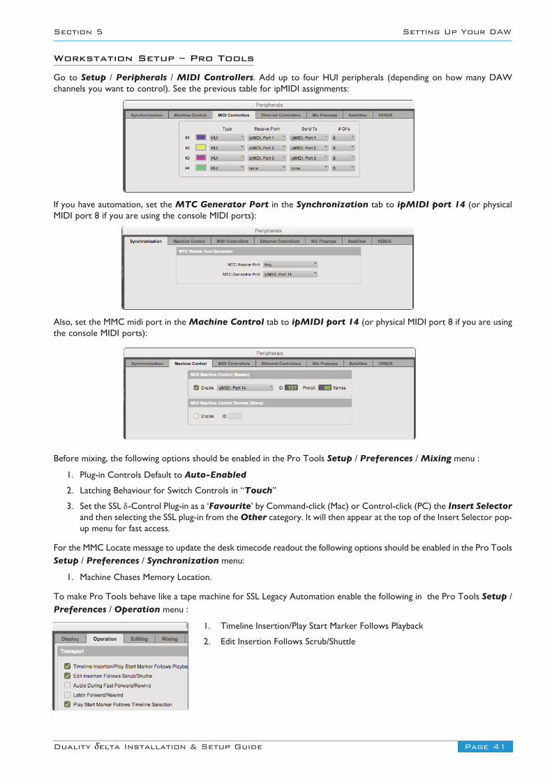
Workstation Setup – Pro Tools
Go to Setup / Peripherals / MIDI Controllers. Add up to four HUI peripherals (depending on how many DAWchannels you want to control). See the previous table for ipMIDI assignments:
If you have automation, set the MTC Generator Port in the Synchronization tab to ipMIDI port 14 (or physicalMIDI port 8 if you are using the console MIDI ports):
Also, set the MMC midi port in the Machine Control tab to ipMIDI port 14 (or physical MIDI port 8 if you are usingthe console MIDI ports):
Before mixing, the following options should be enabled in the Pro Tools Setup / Preferences / Mixing menu :
1. Plug-in Controls Default to Auto-Enabled
2. Latching Behaviour for Switch Controls in “Touch”
3. Set the SSL d-Control Plug-in as a ‘Favourite’ by Command-click (Mac) or Control-click (PC) the Insert Selectorand then selecting the SSL plug-in from the Other category. It will then appear at the top of the Insert Selector pop-up menu for fast access.
For the MMC Locate message to update the desk timecode readout the following options should be enabled in the Pro ToolsSetup / Preferences / Synchronization menu:
1. Machine Chases Memory Location.
To make Pro Tools behave like a tape machine for SSL Legacy Automation enable the following in the Pro Tools Setup /Preferences / Operation menu :
1. Timeline Insertion/Play Start Marker Follows Playback
2. Edit Insertion Follows Scrub/Shuttle
Page 42 Duality δelta Installation & Setup Guide
Setting Up Your DAW Section 5
Workstation Setup – Logic Pro X
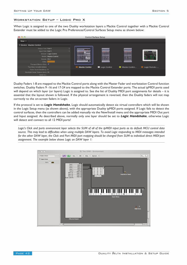
When Logic is assigned to one of the two Duality workstation layers a Mackie Control together with a Mackie ControlExtender must be added to the Logic Pro Preferences/Control Surfaces Setup menu as shown below:
Duality Faders 1-8 are mapped to the Mackie Control ports along with the Master Fader and workstation Control functionswitches. Duality Faders 9 -16 and 17-24 are mapped to the Mackie Control Extender ports. The actual ipMIDI ports usedwill depend on which layer (or layers) Logic is assigned to. See the list of Duality MIDI port assignments for details – it isessential that the layout shown is followed. If the physical arrangement is reversed, then the Duality faders will not mapcorrectly to the on-screen faders in Logic.
If the protocol is set to Logic Handshake, Logic should automatically detect six virtual controllers which will be shownin the Logic Setup menu (as shown above), with the appropriate Duality ipMIDI ports assigned. If Logic fails to detect thecontrol surfaces, then the controllers can be added manually via the New/Install menu and the appropriate MIDI Out portand Input assigned. As described above, normally only one layer should be set to Logic Handshake, otherwise Logicwill detect and connect to all 12 MIDI ports!
Logic’s Click and ports environment layer selects the SUM of all of the ipMIDI input ports as its default MCU control datasource. This may lead to difficulties when using multiple DAW layers. To avoid Logic responding to MIDI messages intendedfor the other DAW layer, the Click and Port MIDI port mapping should be changed from SUM to individual direct MIDI portassignment. The example below shows Logic on DAW layer 1:
Page 43Duality δelta Installation & Setup Guide
Section 5 Setting Up Your DAW
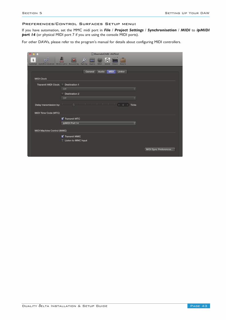
Preferences/Control Surfaces Setup menu:If you have automation, set the MMC midi port in File / Project Settings / Synchronisation / MIDI to ipMIDIport 14 (or physical MIDI port 7 if you are using the console MIDI ports).
For other DAWs, please refer to the program’s manual for details about configuring MIDI controllers.
Page 44 Duality δelta Installation & Setup Guide
Setting Up Your DAW Section 5
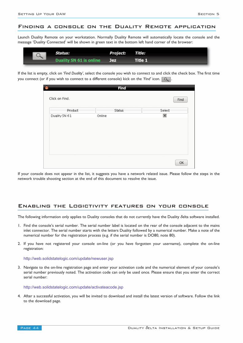
Finding a console on the Duality Remote applicationLaunch Duality Remote on your workstation. Normally Duality Remote will automatically locate the console and themessage ‘Duality Connected’ will be shown in green text in the bottom left hand corner of the browser:
If the list is empty, click on ‘Find Duality’, select the console you wish to connect to and click the check box. The first timeyou connect (or if you wish to connect to a different console) kick on the ‘Find’ icon. .
If your console does not appear in the list, it suggests you have a network related issue. Please follow the steps in thenetwork trouble shooting section at the end of this document to resolve the issue.
Enabling the Logictivity features on your consoleThe following information only applies to Duality consoles that do not currently have the Duality δelta software installed.
1. Find the console’s serial number. The serial number label is located on the rear of the console adjacent to the mainsinlet connector. The serial number starts with the letters Duality followed by a numerical number. Make a note of thenumerical number for the registration process (e.g. if the serial number is DO80, note 80).
2. If you have not registered your console on-line (or you have forgotten your username), complete the on-lineregistration:
http://web.solidstatelogic.com/update/newuser.jsp
3. Navigate to the on-line registration page and enter your activation code and the numerical element of your console’sserial number previously noted. The activation code can only be used once. Please ensure that you enter the correctserial number:
http://web.solidstatelogic.com/update/activateacode.jsp
4. After a successful activation, you will be invited to download and install the latest version of software. Follow the linkto the download page.

Page 45Duality δelta Installation & Setup Guide
Appendices
Appendices
Appendix A – Specifications 46
Appendix B – Connector Details 47
Appendix C – Connector Pinouts 48
Appendix D – Patchbay Layouts 51
Appendix E – Console Footprints 56
Appendix F – Environmental Specification 61
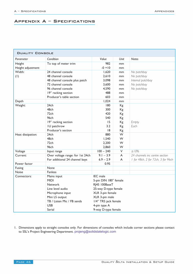
Page 46 Duality δelta Installation & Setup Guide
A – Specifications Appendices
Appendix A – Specifications
Duality ConsoleParameter Condition Value Unit NotesHeight To top of meter trim 982 mmHeight adjustment -0 +10 mmWidth: 24 channel console 1,620 mm No patchbay(1) 48 channel console 2,610 mm No patchbay
48 channel console plus patch 3,098 mm Internal patchbay72 channel console 3,600 mm No patchbay96 channel console 4,590 mm No patchbay19” racking section 488 mmProducer’s table section 603 mm
Depth 1,024 mmWeight: 24ch 180 Kg
48ch 300 Kg72ch 420 Kg96ch 540 Kg19” racking section 15 Kg Empty1U patchrow 3.2 Kg EachProducer’s section 18 Kg
Heat dissipation: 24ch 880 W48ch 1,540 W72ch 2,200 W96ch 2,860 W
Voltage Input range 100 – 240 V ±10%Current: Over voltage range: for 1st 24ch 9.1 – 3.9 A 24 channels inc centre section
For additional 24 channel bays 6.9 – 2.9 A 1 for 48ch, 2 for 72ch, 3 for 96chPower factor 0.95Fusing NoneNoise FanlessConnectors: Mains input IEC male
MIDI 5-pin DIN 180° femaleNetwork RJ45 100BaseTLine level audio 25-way D-type femaleMicrophone input XLR 3-pin femaleMini LS output XLR 3-pin maleTB / Listen Mic / FB sends 1/4” TRS jack femaleUSB 4-pin type ASerial 9-way D-type female
1. Dimensions apply to straight consoles only. For dimensions of consoles which include corner sections please contactto SSL’s Project Engineering Department. [email protected]
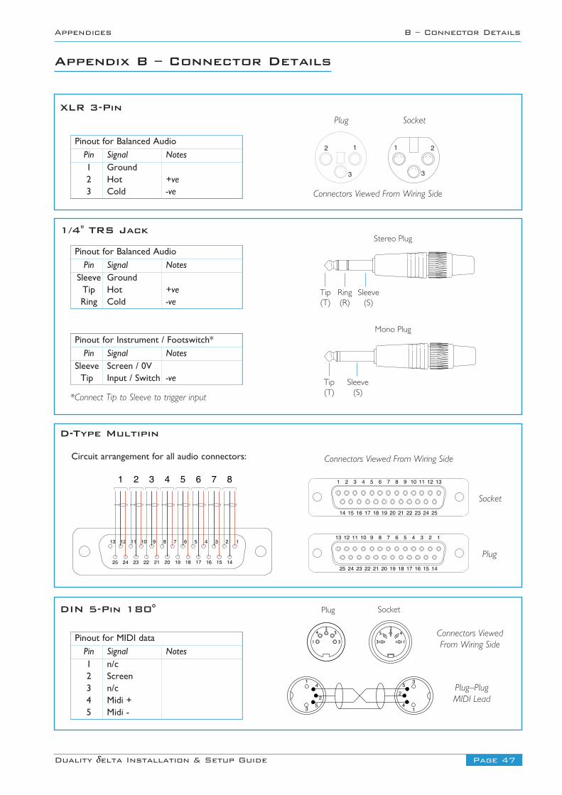
Page 47Duality δelta Installation & Setup Guide
Appendices B – Connector Details
Appendix B – Connector Details
12345678910111213
141516171819202122232425
1 2 3 4 5 6 7 8
Connectors Viewed From Wiring Side
1 2 3 4 5 6 7 8 9 10 11 12 13
14 15 16 17 18 19 20 21 22 23 24 25
12345678910111213
141516171819202122232425
D-Type Multipin
Plug
Socket
Connectors Viewed From Wiring Side
Plug Socket
1 2
3
12
3
XLR 3-Pin
Connectors ViewedFrom Wiring Side
Plug–PlugMIDI Lead
Plug Socket
25
3
4
1
25
3
4
1
DIN 5-Pin 180°
1
2
4
5 31
2
4
53
1/4" TRS Jack
*Connect Tip to Sleeve to trigger input
Stereo Plug
Mono Plug
Tip(T)
Ring(R)
Sleeve(S)
Tip(T)
Sleeve(S)
Pinout for Balanced AudioPin Signal Notes1 Ground2 Hot +ve3 Cold -ve
Pinout for Balanced AudioPin Signal Notes
Sleeve GroundTip Hot +veRing Cold -ve
Pinout for MIDI dataPin Signal Notes1 n/c2 Screen3 n/c4 Midi +5 Midi -
Pinout for Instrument / Footswitch*Pin Signal Notes
Sleeve Screen / 0VTip Input / Switch -ve
Circuit arrangement for all audio connectors:
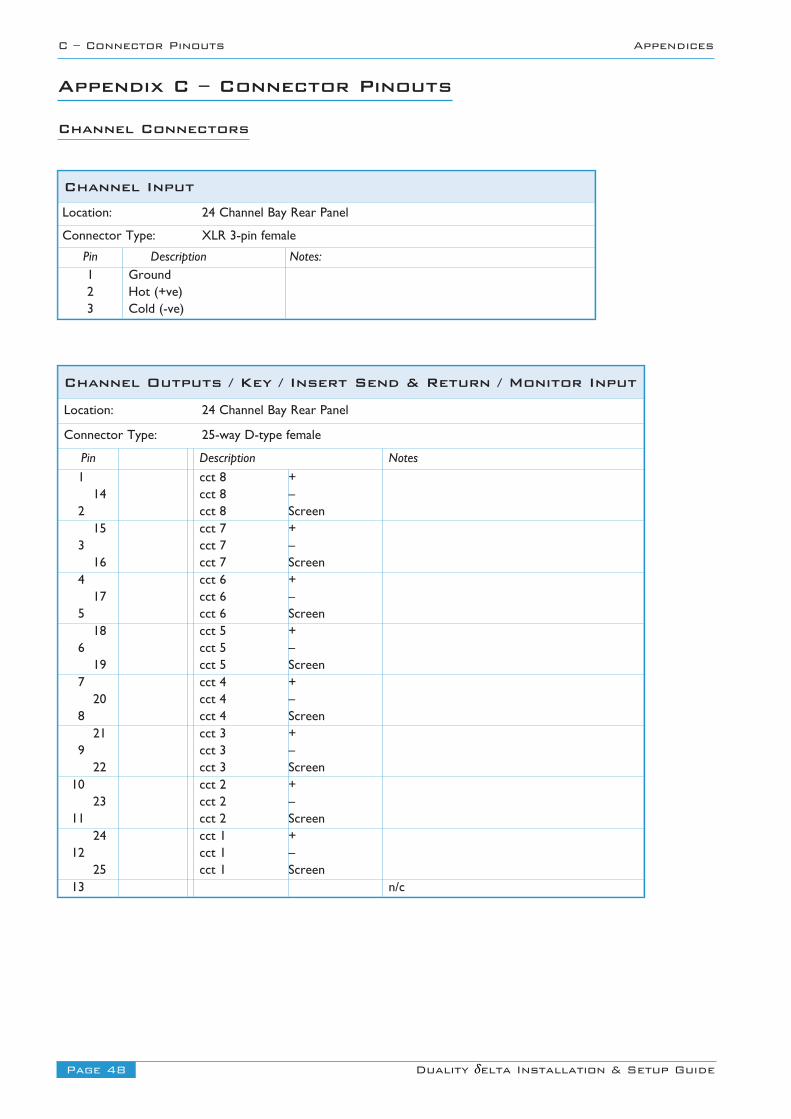
Page 48 Duality δelta Installation & Setup Guide
C – Connector Pinouts Appendices
Channel Outputs / Key / Insert Send & Return / Monitor InputLocation: 24 Channel Bay Rear Panel
Connector Type: 25-way D-type female
Pin Description Notes
1 cct 8 +14 cct 8 –
2 cct 8 Screen15 cct 7 +
3 cct 7 –16 cct 7 Screen
4 cct 6 +17 cct 6 –
5 cct 6 Screen18 cct 5 +
6 cct 5 –19 cct 5 Screen
7 cct 4 +20 cct 4 –
8 cct 4 Screen21 cct 3 +
9 cct 3 –22 cct 3 Screen
10 cct 2 +23 cct 2 –
11 cct 2 Screen24 cct 1 +
12 cct 1 –25 cct 1 Screen
13 n/c
Channel InputLocation: 24 Channel Bay Rear Panel
Connector Type: XLR 3-pin female
Pin Description Notes: 1 Ground2 Hot (+ve)3 Cold (-ve)
Appendix C – Connector Pinouts
Channel Connectors
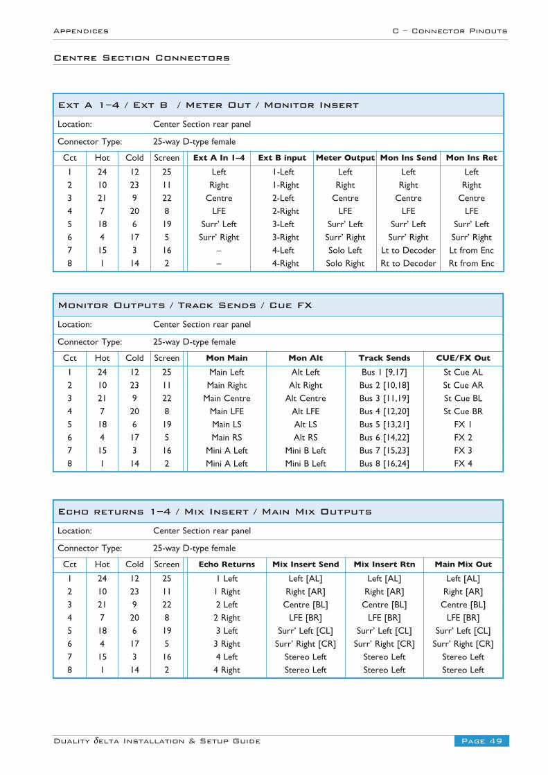
Page 49Duality δelta Installation & Setup Guide
Appendices C – Connector Pinouts
Centre Section Connectors
Ext A 1–4 / Ext B / Meter Out / Monitor Insert
Location: Center Section rear panel
Connector Type: 25-way D-type female
Cct Hot Cold Screen Ext A In 1–4 Ext B input Meter Output Mon Ins Send Mon Ins Ret
1 24 12 25 Left 1-Left Left Left Left2 10 23 11 Right 1-Right Right Right Right3 21 9 22 Centre 2-Left Centre Centre Centre4 7 20 8 LFE 2-Right LFE LFE LFE5 18 6 19 Surr’ Left 3-Left Surr’ Left Surr’ Left Surr’ Left6 4 17 5 Surr’ Right 3-Right Surr’ Right Surr’ Right Surr’ Right7 15 3 16 – 4-Left Solo Left Lt to Decoder Lt from Enc8 1 14 2 – 4-Right Solo Right Rt to Decoder Rt from Enc
Monitor Outputs / Track Sends / Cue FX
Location: Center Section rear panel
Connector Type: 25-way D-type female
Cct Hot Cold Screen Mon Main Mon Alt Track Sends CUE/FX Out
1 24 12 25 Main Left Alt Left Bus 1 [9,17] St Cue AL2 10 23 11 Main Right Alt Right Bus 2 [10,18] St Cue AR3 21 9 22 Main Centre Alt Centre Bus 3 [11,19] St Cue BL4 7 20 8 Main LFE Alt LFE Bus 4 [12,20] St Cue BR5 18 6 19 Main LS Alt LS Bus 5 [13,21] FX 16 4 17 5 Main RS Alt RS Bus 6 [14,22] FX 27 15 3 16 Mini A Left Mini B Left Bus 7 [15,23] FX 38 1 14 2 Mini A Left Mini B Left Bus 8 [16,24] FX 4
Echo returns 1–4 / Mix Insert / Main Mix Outputs
Location: Center Section rear panel
Connector Type: 25-way D-type female
Cct Hot Cold Screen Echo Returns Mix Insert Send Mix Insert Rtn Main Mix Out
1 24 12 25 1 Left Left [AL] Left [AL] Left [AL]2 10 23 11 1 Right Right [AR] Right [AR] Right [AR]3 21 9 22 2 Left Centre [BL] Centre [BL] Centre [BL]4 7 20 8 2 Right LFE [BR] LFE [BR] LFE [BR]5 18 6 19 3 Left Surr’ Left [CL] Surr’ Left [CL] Surr’ Left [CL]6 4 17 5 3 Right Surr’ Right [CR] Surr’ Right [CR] Surr’ Right [CR]7 15 3 16 4 Left Stereo Left Stereo Left Stereo Left8 1 14 2 4 Right Stereo Left Stereo Left Stereo Left
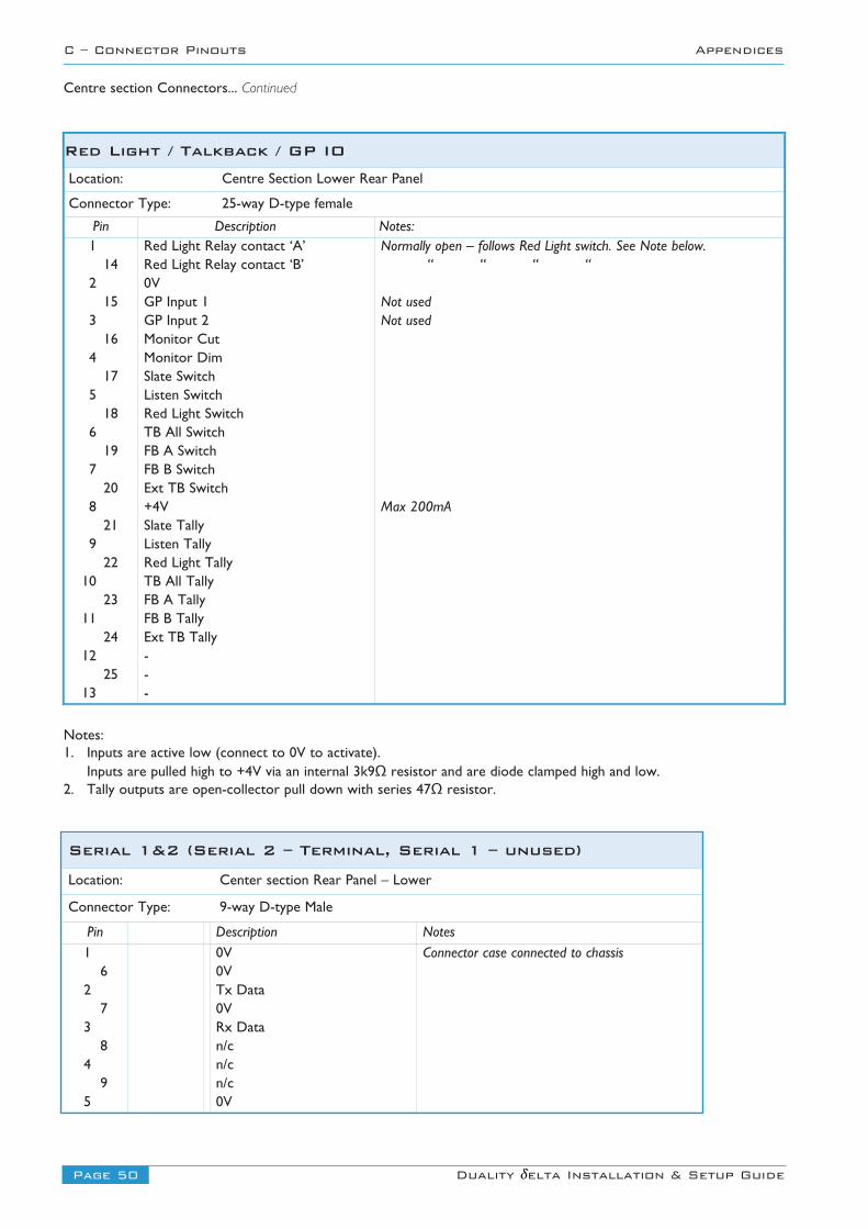
Page 50 Duality δelta Installation & Setup Guide
C – Connector Pinouts Appendices
Centre section Connectors... Continued
Serial 1&2 (Serial 2 – Terminal, Serial 1 – unused)Location: Center section Rear Panel – Lower
Connector Type: 9-way D-type Male
Pin Description Notes
1 0V Connector case connected to chassis6 0V
2 Tx Data7 0V
3 Rx Data8 n/c
4 n/c9 n/c
5 0V
Notes:1. Inputs are active low (connect to 0V to activate).
Inputs are pulled high to +4V via an internal 3k9Ω resistor and are diode clamped high and low.2. Tally outputs are open-collector pull down with series 47Ω resistor.
Red Light / Talkback / GP IOLocation: Centre Section Lower Rear Panel
Connector Type: 25-way D-type female
Pin Description Notes: 1 Red Light Relay contact ‘A’ Normally open – follows Red Light switch. See Note below.14 Red Light Relay contact ‘B’ “ “ “ “
2 0V15 GP Input 1 Not used
3 GP Input 2 Not used16 Monitor Cut
4 Monitor Dim17 Slate Switch
5 Listen Switch18 Red Light Switch
6 TB All Switch19 FB A Switch
7 FB B Switch20 Ext TB Switch
8 +4V Max 200mA21 Slate Tally
9 Listen Tally22 Red Light Tally
10 TB All Tally23 FB A Tally
11 FB B Tally24 Ext TB Tally
12 -25 -
13 -
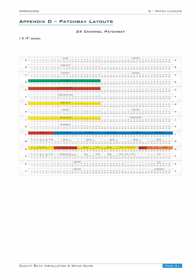
Page 51Duality δelta Installation & Setup Guide
Appendices D – Patch Layouts
Appendix D – Patchbay Layouts
24 Channel Patchbay
1 X 19” section.
17 18 19 20 21 22 23 249 10 11 12 13 14 15 161 2 3 4 5 6 7 8 25 26 27 28 29 30 31 32 33 34 35 36 37 38 39 40 41 42 43 44 45 46 47 48
17 18 19 20 21 22 23 249 10 11 12 13 14 15 161 2 3 4 5 6 7 8 25 26 27 28 29 30 31 32 33 34 35 36 37 38 39 40 41 42 43 44 45 46 47 48
17 18 19 20 21 22 23 249 10 11 12 13 14 15 161 2 3 4 5 6 7 8 25 26 27 28 29 30 31 32 33 34 35 36 37 38 39 40 41 42 43 44 45 46 47 48
17 18 19 20 21 22 23 249 10 11 12 13 14 15 161 2 3 4 5 6 7 8 25 26 27 28 29 30 31 32 33 34 35 36 37 38 39 40 41 42 43 44 45 46 47 48
17 18 19 20 21 22 23 249 10 11 12 13 14 15 161 2 3 4 5 6 7 8 25 26 27 28 29 30 31 32 33 34 35 36 37 38 39 40 41 42 43 44 45 46 47 48
17 18 19 20 21 22 23 249 10 11 12 13 14 15 161 2 3 4 5 6 7 8 25 26 27 28 29 30 31 32 33 34 35 36 37 38 39 40 41 42 43 44 45 46 47 48
17 18 19 20 21 22 23 249 10 11 12 13 14 15 161 2 3 4 5 6 7 8 25 26 27 28 29 30 31 32 33 34 35 36 37 38 39 40 41 42 43 44 45 46 47 48
17 18 19 20 21 22 23 249 10 11 12 13 14 15 161 2 3 4 5 6 7 8 25 26 27 28 29 30 31 32 33 34 35 36 37 38 39 40 41 42 43 44 45 46 47 48
17 18 19 20 21 22 23 249 10 11 12 13 14 15 161 2 3 4 5 6 7 8 25 26 27 28 29 30 31 32 33 34 35 36 37 38 39 40 41 42 43 44 45 46 47 48
17 18 19 20 21 22 23 249 10 11 12 13 14 15 161 2 3 4 5 6 7 8 25 26 27 28 29 30 31 32 33 34 35 36 37 38 39 40 41 42 43 44 45 46 47 48
DAW OUTPUTS USER OPTION9 10 11 12 13 14 15 161 2 3 4 5 6 7 8 17 18 19 20 21 22 23 24 9 10 11 12 13 14 15 161 2 3 4 5 6 7 8 17 18 19 20 21 22 23 24
MONITOR INPUTS9 10 11 12 13 14 15 161 2 3 4 5 6 7 8 17 18 19 20 21 22 23 24 9 10 11 12 13 14 15 161 2 3 4 5 6 7 8 17 18 19 20 21 22 23 24
CHANNEL INSERT SENDS9 10 11 12 13 14 15 161 2 3 4 5 6 7 8 17 18 19 20 21 22 23 24 9 10 11 12 13 14 15 161 2 3 4 5 6 7 8 17 18 19 20 21 22 23 24
CHANNEL OUTPUTS
9 10 11 12 13 14 15 161 2 3 4 5 6 7 8 17 18 19 20 21 22 23 24 9 10 11 12 13 14 15 161 2 3 4 5 6 7 8 17 18 19 20 21 22 23 24
DAW INPUTS USER OPTION
9 10 11 12 13 14 15 161 2 3 4 5 6 7 8 17 18 19 20 21 22 23 24 9 10 11 12 13 14 15 161 2 3 4 5 6 7 8 17 18 19 20 21 22 23 24
9 10 11 12 13 14 15 161 2 3 4 5 6 7 8 17 18 19 20 21 22 23 24 9 10 11 12 13 14 15 161 2 3 4 5 6 7 8 17 18 19 20 21 22 23 24
CHANNEL INSERT RETURNS
TRACK BUS OUTPUTS
RECORDER INPUTS
CHANNEL KEY INPUTS9 10 11 12 13 14 15 161 2 3 4 5 6 7 8 17 18 19 20 21 22 23 24 9 10 11 12 13 14 15 161 2 3 4 5 6 7 8 17 18 19 20 21 22 23 24
9 10 11 12 13 14 15 161 2 3 4 5 6 7 8 17 18 19 20 21 22 23 24 9 10 11 12 13 14 15 161 2 3 4 5 6 7 8 17 18 19 20 21 22 23 24
MIC LINES USER OPTION9 10 11 12 13 14 15 161 2 3 4 5 6 7 8 17 18 19 20 21 22 23 24 9 10 11 12 13 14 15 161 2 3 4 5 6 7 8 17 18 19 20 21 22 23 24
CHANNEL INPUTS9 10 11 12 13 14 15 161 2 3 4 5 6 7 8 17 18 19 20 21 22 23 24 9 10 11 12 13 14 15 161 2 3 4 5 6 7 8 17 18 19 20 21 22 23 24
17 18 19 20 21 22 23 249 10 11 12 13 14 15 161 2 3 4 5 6 7 8 25 26 27 28 29 30 31 32 33 34 35 36 37 38 39 40 41 42 43 44 45 46 47 48
17 18 19 20 21 22 23 249 10 11 12 13 14 15 161 2 3 4 5 6 7 8 25 26 27 28 29 30 31 32 33 34 35 36 37 38 39 40 41 42 43 44 45 46 47 48
17 18 19 20 21 22 23 249 10 11 12 13 14 15 161 2 3 4 5 6 7 8 25 26 27 28 29 30 31 32 33 34 35 36 37 38 39 40 41 42 43 44 45 46 47 48
17 18 19 20 21 22 23 249 10 11 12 13 14 15 161 2 3 4 5 6 7 8 25 26 27 28 29 30 31 32 33 34 35 36 37 38 39 40 41 42 43 44 45 46 47 48
17 18 19 20 21 22 23 249 10 11 12 13 14 15 161 2 3 4 5 6 7 8 25 26 27 28 29 30 31 32 33 34 35 36 37 38 39 40 41 42 43 44 45 46 47 48
17 18 19 20 21 22 23 249 10 11 12 13 14 15 161 2 3 4 5 6 7 8 25 26 27 28 29 30 31 32 33 34 35 36 37 38 39 40 41 42 43 44 45 46 47 48
EXT A3 SOURCE1 2 3 4 5 6 7 8
EXT A2 SOURCE1 2 3 4 5 6 7 8
MIX INSERTAL AR BL BR CL CR L R
EXT A1 SOURCE1 2 3 4 5 6 7 8
EXT A4 SOURCE1 2 3 4 5 6 7 8
EXT B SOURCE1 2 3 4 5 6 7 8
ALL R C LFE LS RS L R
EXT A1 INAR BL BR CL CR ST MIXL R C LFE LS RS
EXT A2 INL R C LFE LS RS
EXT A3 INL R C LFE LS RS
EXT A4 INL R C LFE LS RS
EXT B IN1L 1R 2L 2R 3L 3R 4L 4R
MAIN LS BAL AR BL BR CL CR L R
MINI BMAIN LS AMIX OUTPUTSAL AR BL BR CL CR L R
MONITOR INSERT SEND1 2 3 4L R C LFE LS RS Lt Rt
DECODER AL AR BL BR CL CR L RMINI A
L R L RF/B A OUT F/B B OUT
L RCUE A
L RCUE B FX SENDS
INLSN
OUTLSN
OUTT/B OSC
ALL R C LFE LS RS L R
AR BL BR CL CR ST MIX AMP INL R C LFE LS RS
FX INMONITOR INSERT RTNL R C LFE LS RS Lt Rt
ENCODER L RAMP IN AMP IN
L R C LFE LS RS L RAMP IN
L RAMP A
L RAMP B
1 2 3 4L R L R
USER OPTION9 10 11 12 13 14 15 161 2 3 4 5 6 7 8 17 18 19 20 21 22 23 24 25 26 27 28 29 30 31 32
FX OUT1L 1R 2L 2R 3L 3R 4L 4R
9 10 11 12 13 14 15 161 2 3 4 5 6 7 8 17 18 19 20 21 22 23 24USER OPTION
25 26 27 28 29 30 31 32ECHO RETURN IN
1L 1R 2L 2R 3L 3R 4L 4R
D
E
F
A
B
C
G
H
J
K
L
M
N
P
R
S
D
E
F
A
B
C
G
H
J
K
L
M
N
P
R
S
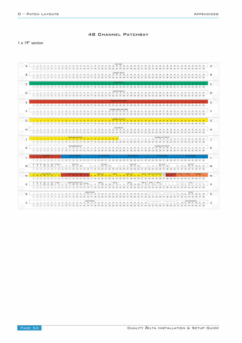
Page 52 Duality δelta Installation & Setup Guide
D – Patch Layouts Appendices
17 18 19 20 21 22 23 249 10 11 12 13 14 15 161 2 3 4 5 6 7 8 25 26 27 28 29 30 31 32 33 34 35 36 37 38 39 40 41 42 43 44 45 46 47 48
17 18 19 20 21 22 23 249 10 11 12 13 14 15 161 2 3 4 5 6 7 8 25 26 27 28 29 30 31 32 33 34 35 36 37 38 39 40 41 42 43 44 45 46 47 48
17 18 19 20 21 22 23 249 10 11 12 13 14 15 161 2 3 4 5 6 7 8 25 26 27 28 29 30 31 32 33 34 35 36 37 38 39 40 41 42 43 44 45 46 47 48
17 18 19 20 21 22 23 249 10 11 12 13 14 15 161 2 3 4 5 6 7 8 25 26 27 28 29 30 31 32 33 34 35 36 37 38 39 40 41 42 43 44 45 46 47 48
17 18 19 20 21 22 23 249 10 11 12 13 14 15 161 2 3 4 5 6 7 8 25 26 27 28 29 30 31 32 33 34 35 36 37 38 39 40 41 42 43 44 45 46 47 48
17 18 19 20 21 22 23 249 10 11 12 13 14 15 161 2 3 4 5 6 7 8 25 26 27 28 29 30 31 32 33 34 35 36 37 38 39 40 41 42 43 44 45 46 47 48
17 18 19 20 21 22 23 249 10 11 12 13 14 15 161 2 3 4 5 6 7 8 25 26 27 28 29 30 31 32 33 34 35 36 37 38 39 40 41 42 43 44 45 46 47 48
17 18 19 20 21 22 23 249 10 11 12 13 14 15 161 2 3 4 5 6 7 8 25 26 27 28 29 30 31 32 33 34 35 36 37 38 39 40 41 42 43 44 45 46 47 48
17 18 19 20 21 22 23 249 10 11 12 13 14 15 161 2 3 4 5 6 7 8 25 26 27 28 29 30 31 32 33 34 35 36 37 38 39 40 41 42 43 44 45 46 47 48
17 18 19 20 21 22 23 249 10 11 12 13 14 15 161 2 3 4 5 6 7 8 25 26 27 28 29 30 31 32 33 34 35 36 37 38 39 40 41 42 43 44 45 46 47 48
17 18 19 20 21 22 23 249 10 11 12 13 14 15 161 2 3 4 5 6 7 8 25 26 27 28 29 30 31 32 33 34 35 36 37 38 39 40 41 42 43 44 45 46 47 48
17 18 19 20 21 22 23 249 10 11 12 13 14 15 161 2 3 4 5 6 7 8 25 26 27 28 29 30 31 32 33 34 35 36 37 38 39 40 41 42 43 44 45 46 47 48
17 18 19 20 21 22 23 249 10 11 12 13 14 15 161 2 3 4 5 6 7 8 25 26 27 28 29 30 31 32 33 34 35 36 37 38 39 40 41 42 43 44 45 46 47 48
17 18 19 20 21 22 23 249 10 11 12 13 14 15 161 2 3 4 5 6 7 8 25 26 27 28 29 30 31 32 33 34 35 36 37 38 39 40 41 42 43 44 45 46 47 48
17 18 19 20 21 22 23 249 10 11 12 13 14 15 161 2 3 4 5 6 7 8 25 26 27 28 29 30 31 32 33 34 35 36 37 38 39 40 41 42 43 44 45 46 47 48
17 18 19 20 21 22 23 249 10 11 12 13 14 15 161 2 3 4 5 6 7 8 25 26 27 28 29 30 31 32 33 34 35 36 37 38 39 40 41 42 43 44 45 46 47 48
EXT A3 SOURCE1 2 3 4 5 6 7 8
EXT A2 SOURCE1 2 3 4 5 6 7 8
MIX INSERTAL AR BL BR CL CR L R
EXT A1 SOURCE1 2 3 4 5 6 7 8
EXT A4 SOURCE1 2 3 4 5 6 7 8
EXT B SOURCE1 2 3 4 5 6 7 8
ALL R C LFE LS RS L R
EXT A1 INAR BL BR CL CR ST MIXL R C LFE LS RS
EXT A2 INL R C LFE LS RS
EXT A3 INL R C LFE LS RS
EXT A4 INL R C LFE LS RS
EXT B IN1L 1R 2L 2R 3L 3R 4L 4R
MAIN LS BAL AR BL BR CL CR L R
MINI BMAIN LS AMIX OUTPUTSAL AR BL BR CL CR L R
MONITOR INSERT SEND1 2 3 4L R C LFE LS RS Lt Rt
DECODER AL AR BL BR CL CR L RMINI A
L R L RF/B A OUT F/B B OUT
L RCUE A
L RCUE B FX SENDS
INLSN
OUTLSN
OUTT/B OSC
ALL R C LFE LS RS L R
AR BL BR CL CR ST MIX AMP INL R C LFE LS RS
FX INMONITOR INSERT RTNL R C LFE LS RS Lt Rt
ENCODER L RAMP IN AMP IN
L R C LFE LS RS L RAMP IN
L RAMP A
L RAMP B
1 2 3 4L R L R
USER OPTION9 10 11 12 13 14 15 161 2 3 4 5 6 7 8 17 18 19 20 21 22 23 24 25 26 27 28 29 30 31 32
FX OUT1L 1R 2L 2R 3L 3R 4L 4R
9 10 11 12 13 14 15 161 2 3 4 5 6 7 8 17 18 19 20 21 22 23 24USER OPTION
25 26 27 28 29 30 31 32ECHO RETURN IN
1L 1R 2L 2R 3L 3R 4L 4R
MIC LINES9 10 11 12 13 14 15 161 2 3 4 5 6 7 8 17 18 19 20 21 22 23 24 33 34 35 36 37 38 39 4025 26 27 28 29 30 31 32 41 42 43 44 45 46 47 48
CHANNEL INPUTS9 10 11 12 13 14 15 161 2 3 4 5 6 7 8 17 18 19 20 21 22 23 24 33 34 35 36 37 38 39 4025 26 27 28 29 30 31 32 41 42 43 44 45 46 47 48
DAW OUTPUTS9 10 11 12 13 14 15 161 2 3 4 5 6 7 8 17 18 19 20 21 22 23 24 33 34 35 36 37 38 39 4025 26 27 28 29 30 31 32 41 42 43 44 45 46 47 48
MONITOR INPUTS9 10 11 12 13 14 15 161 2 3 4 5 6 7 8 17 18 19 20 21 22 23 24 33 34 35 36 37 38 39 4025 26 27 28 29 30 31 32 41 42 43 44 45 46 47 48
CHANNEL INSERT SENDS9 10 11 12 13 14 15 161 2 3 4 5 6 7 8 17 18 19 20 21 22 23 24 33 34 35 36 37 38 39 4025 26 27 28 29 30 31 32 41 42 43 44 45 46 47 48
9 10 11 12 13 14 15 161 2 3 4 5 6 7 8 17 18 19 20 21 22 23 24CHANNEL INSERT RETURNS
33 34 35 36 37 38 39 4025 26 27 28 29 30 31 32 41 42 43 44 45 46 47 48
CHANNEL OUTPUTS9 10 11 12 13 14 15 161 2 3 4 5 6 7 8 17 18 19 20 21 22 23 24 33 34 35 36 37 38 39 4025 26 27 28 29 30 31 32 41 42 43 44 45 46 47 48
DAW INPUTS9 10 11 12 13 14 15 161 2 3 4 5 6 7 8 17 18 19 20 21 22 23 24 33 34 35 36 37 38 39 4025 26 27 28 29 30 31 32 41 42 43 44 45 46 47 48
TRACK BUS OUTPUTS CHANNEL KEY INPUTS9 10 11 12 13 14 15 161 2 3 4 5 6 7 8 17 18 19 20 21 22 23 24 9 10 11 12 13 14 15 161 2 3 4 5 6 7 8 17 18 19 20 21 22 23 24
RECORDER INPUTS9 10 11 12 13 14 15 161 2 3 4 5 6 7 8 17 18 19 20 21 22 23 24 33 34 35 36 37 38 39 4025 26 27 28 29 30 31 32 41 42 43 44 45 46 47 48
CHANNEL KEY INPUTS
D
E
F
A
B
C
G
H
J
K
L
M
N
P
R
S
D
E
F
A
B
C
G
H
J
K
L
M
N
P
R
S
48 Channel Patchbay
1 x 19” section
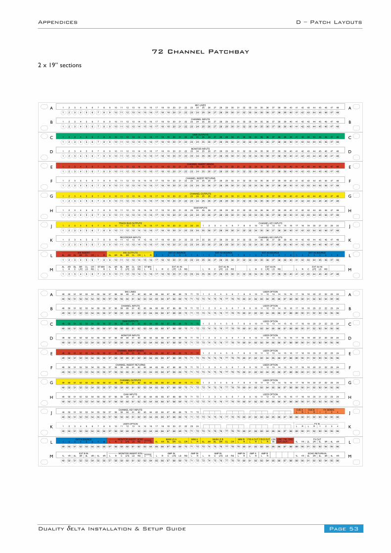
Page 53Duality δelta Installation & Setup Guide
Appendices D – Patch Layouts
17 18 19 20 21 22 23 249 10 11 12 13 14 15 161 2 3 4 5 6 7 8 25 26 27 28 29 30 31 32 33 34 35 36 37 38 39 40 41 42 43 44 45 46 47 48
17 18 19 20 21 22 23 249 10 11 12 13 14 15 161 2 3 4 5 6 7 8 25 26 27 28 29 30 31 32 33 34 35 36 37 38 39 40 41 42 43 44 45 46 47 48
17 18 19 20 21 22 23 249 10 11 12 13 14 15 161 2 3 4 5 6 7 8 25 26 27 28 29 30 31 32 33 34 35 36 37 38 39 40 41 42 43 44 45 46 47 48
17 18 19 20 21 22 23 249 10 11 12 13 14 15 161 2 3 4 5 6 7 8 25 26 27 28 29 30 31 32 33 34 35 36 37 38 39 40 41 42 43 44 45 46 47 48
17 18 19 20 21 22 23 249 10 11 12 13 14 15 161 2 3 4 5 6 7 8 25 26 27 28 29 30 31 32 33 34 35 36 37 38 39 40 41 42 43 44 45 46 47 48
17 18 19 20 21 22 23 249 10 11 12 13 14 15 161 2 3 4 5 6 7 8 25 26 27 28 29 30 31 32 33 34 35 36 37 38 39 40 41 42 43 44 45 46 47 48
17 18 19 20 21 22 23 249 10 11 12 13 14 15 161 2 3 4 5 6 7 8 25 26 27 28 29 30 31 32 33 34 35 36 37 38 39 40 41 42 43 44 45 46 47 48
17 18 19 20 21 22 23 249 10 11 12 13 14 15 161 2 3 4 5 6 7 8 25 26 27 28 29 30 31 32 33 34 35 36 37 38 39 40 41 42 43 44 45 46 47 48
17 18 19 20 21 22 23 249 10 11 12 13 14 15 161 2 3 4 5 6 7 8 25 26 27 28 29 30 31 32 33 34 35 36 37 38 39 40 41 42 43 44 45 46 47 48
17 18 19 20 21 22 23 249 10 11 12 13 14 15 161 2 3 4 5 6 7 8 25 26 27 28 29 30 31 32 33 34 35 36 37 38 39 40 41 42 43 44 45 46 47 48
USER OPTION9 10 11 12 13 14 15 161 2 3 4 5 6 7 8 17 18 19 20 21 22 23 24 33 34 35 36 37 38 39 4025 26 27 28 29 30 31 32 41 42 43 44 45 46 47 48
17 18 19 20 21 22 23 249 10 11 12 13 14 15 161 2 3 4 5 6 7 8 25 26 27 28 29 30 31 32 33 34 35 36 37 38 39 40 41 42 43 44 45 46 47 48
17 18 19 20 21 22 23 249 10 11 12 13 14 15 161 2 3 4 5 6 7 8 25 26 27 28 29 30 31 32 33 34 35 36 37 38 39 40 41 42 43 44 45 46 47 48
EXT A3 SOURCE1 2 3 4 5 6 7 8
EXT A2 SOURCE1 2 3 4 5 6 7 8
MIX INSERTAL AR BL BR CL CR L R
EXT A1 SOURCE1 2 3 4 5 6 7 8
EXT A4 SOURCE1 2 3 4 5 6 7 8
ALL R C LFE LS RS L R
EXT A1 INAR BL BR CL CR ST MIXL R C LFE LS RS
EXT A2 INL R C LFE LS RS
EXT A3 INL R C LFE LS RS
EXT A4 INL R C LFE LS RS
MIX OUTPUTSAL AR BL BR CL CR L R
ALL R C LFE LS RS L R
AR BL BR CL CR ST MIX
MIC LINES9 10 11 12 13 14 15 161 2 3 4 5 6 7 8 17 18 19 20 21 22 23 24 33 34 35 36 37 38 39 4025 26 27 28 29 30 31 32 41 42 43 44 45 46 47 48
CHANNEL INPUTS9 10 11 12 13 14 15 161 2 3 4 5 6 7 8 17 18 19 20 21 22 23 24 33 34 35 36 37 38 39 4025 26 27 28 29 30 31 32 41 42 43 44 45 46 47 48
DAW OUTPUTS9 10 11 12 13 14 15 161 2 3 4 5 6 7 8 17 18 19 20 21 22 23 24 33 34 35 36 37 38 39 4025 26 27 28 29 30 31 32 41 42 43 44 45 46 47 48
MONITOR INPUTS9 10 11 12 13 14 15 161 2 3 4 5 6 7 8 17 18 19 20 21 22 23 24 33 34 35 36 37 38 39 4025 26 27 28 29 30 31 32 41 42 43 44 45 46 47 48
CHANNEL INSERT SENDS9 10 11 12 13 14 15 161 2 3 4 5 6 7 8 17 18 19 20 21 22 23 24 33 34 35 36 37 38 39 4025 26 27 28 29 30 31 32 41 42 43 44 45 46 47 48
9 10 11 12 13 14 15 161 2 3 4 5 6 7 8 17 18 19 20 21 22 23 24CHANNEL INSERT RETURNS
33 34 35 36 37 38 39 4025 26 27 28 29 30 31 32 41 42 43 44 45 46 47 48
CHANNEL OUTPUTS9 10 11 12 13 14 15 161 2 3 4 5 6 7 8 17 18 19 20 21 22 23 24 33 34 35 36 37 38 39 4025 26 27 28 29 30 31 32 41 42 43 44 45 46 47 48
DAW INPUTS9 10 11 12 13 14 15 161 2 3 4 5 6 7 8 17 18 19 20 21 22 23 24 33 34 35 36 37 38 39 4025 26 27 28 29 30 31 32 41 42 43 44 45 46 47 48
TRACK BUS OUTPUTS CHANNEL KEY INPUTS9 10 11 12 13 14 15 161 2 3 4 5 6 7 8 17 18 19 20 21 22 23 24 9 10 11 12 13 14 15 161 2 3 4 5 6 7 8 17 18 19 20 21 22 23 24
RECORDER INPUTS9 10 11 12 13 14 15 161 2 3 4 5 6 7 8 17 18 19 20 21 22 23 24 33 34 35 36 37 38 39 4025 26 27 28 29 30 31 32 41 42 43 44 45 46 47 48
CHANNEL KEY INPUTS
D
E
F
A
B
C
G
H
J
K
L
M
D
E
F
A
B
C
G
H
J
K
L
M
MAIN LS BAL AR BL BR CL CR L R
MINI BMAIN LS AMONITOR INSERT SENDL R C LFE LS RS Lt Rt
DECODER AL AR BL BR CL CR L RMINI A
L R L RF/B A OUT F/B B OUT
INLSN
OUTLSN
OUTT/B OSC
AMP INL R C LFE LS RS
FX IN
MONITOR INSERT RTNL R C LFE LS RS Lt Rt
ENCODER L RAMP IN AMP IN
L R C LFE LS RS L RAMP IN
L RAMP A
L RAMP B
1 2 3 4L R L R
USER OPTION
FX OUT1L 1R 2L 2R 3L 3R 4L 4R
ECHO RETURN IN1L 1R 2L 2R 3L 3R 4L 4R
MIC LINES
CHANNEL INPUTS
DAW OUTPUTS
MONITOR INPUTS
CHANNEL INSERT SENDS
CHANNEL INSERT RETURNS
CHANNEL OUTPUTS
DAW INPUTS
D
E
F
A
B
C
G
H
J
K
L
M
D
E
F
A
B
C
G
H
J
K
L
M
65 66 67 68 69 70 71 7257 58 59 60 61 62 63 6449 50 51 52 53 54 55 56
65 66 67 68 69 70 71 7257 58 59 60 61 62 63 6449 50 51 52 53 54 55 56
65 66 67 68 69 70 71 7257 58 59 60 61 62 63 6449 50 51 52 53 54 55 56
65 66 67 68 69 70 71 7257 58 59 60 61 62 63 6449 50 51 52 53 54 55 56
65 66 67 68 69 70 71 7257 58 59 60 61 62 63 6449 50 51 52 53 54 55 56
65 66 67 68 69 70 71 7257 58 59 60 61 62 63 6449 50 51 52 53 54 55 56
65 66 67 68 69 70 71 7257 58 59 60 61 62 63 6449 50 51 52 53 54 55 56
65 66 67 68 69 70 71 7257 58 59 60 61 62 63 6449 50 51 52 53 54 55 56
65 66 67 68 69 70 71 7257 58 59 60 61 62 63 6449 50 51 52 53 54 55 56
65 66 67 68 69 70 71 7257 58 59 60 61 62 63 6449 50 51 52 53 54 55 56
73 74 75 76 77 78 79 80 81 82 83 84 85 86 87 88 89 90 91 92 93 94 95 96
73 74 75 76 77 78 79 80 81 82 83 84 85 86 87 88 89 90 91 92 93 94 95 96
65 66 67 68 69 70 71 7257 58 59 60 61 62 63 6449 50 51 52 53 54 55 56
65 66 67 68 69 70 71 7257 58 59 60 61 62 63 6449 50 51 52 53 54 55 56
73 74 75 76 77 78 79 80 81 82 83 84 85 86 87 88 89 90 91 92 93 94 95 96
73 74 75 76 77 78 79 80 81 82 83 84 85 86 87 88 89 90 91 92 93 94 95 96
65 66 67 68 69 70 71 7257 58 59 60 61 62 63 6449 50 51 52 53 54 55 56
65 66 67 68 69 70 71 7257 58 59 60 61 62 63 6449 50 51 52 53 54 55 56
73 74 75 76 77 78 79 80 81 82 83 84 85 86 87 88 89 90 91 92 93 94 95 96
73 74 75 76 77 78 79 80 81 82 83 84 85 86 87 88 89 90 91 92 93 94 95 96
65 66 67 68 69 70 71 7257 58 59 60 61 62 63 6449 50 51 52 53 54 55 56
65 66 67 68 69 70 71 7257 58 59 60 61 62 63 6449 50 51 52 53 54 55 56
73 74 75 76 77 78 79 80 81 82 83 84 85 86 87 88 89 90 91 92 93 94 95 96
73 74 75 76 77 78 79 80 81 82 83 84 85 86 87 88 89 90 91 92 93 94 95 96
65 66 67 68 69 70 71 7257 58 59 60 61 62 63 6449 50 51 52 53 54 55 56
65 66 67 68 69 70 71 7257 58 59 60 61 62 63 6449 50 51 52 53 54 55 56
73 74 75 76 77 78 79 80 81 82 83 84 85 86 87 88 89 90 91 92 93 94 95 96
73 74 75 76 77 78 79 80 81 82 83 84 85 86 87 88 89 90 91 92 93 94 95 96
65 66 67 68 69 70 71 7257 58 59 60 61 62 63 6449 50 51 52 53 54 55 56
65 66 67 68 69 70 71 7257 58 59 60 61 62 63 6449 50 51 52 53 54 55 56
73 74 75 76 77 78 79 80 81 82 83 84 85 86 87 88 89 90 91 92 93 94 95 96
73 74 75 76 77 78 79 80 81 82 83 84 85 86 87 88 89 90 91 92 93 94 95 96
9 10 11 12 13 14 15 161 2 3 4 5 6 7 8 17 18 19 20 21 22 23 24
9 10 11 12 13 14 15 161 2 3 4 5 6 7 8 17 18 19 20 21 22 23 24
9 10 11 12 13 14 15 161 2 3 4 5 6 7 8 17 18 19 20 21 22 23 24
9 10 11 12 13 14 15 161 2 3 4 5 6 7 8 17 18 19 20 21 22 23 24
9 10 11 12 13 14 15 161 2 3 4 5 6 7 8 17 18 19 20 21 22 23 24
9 10 11 12 13 14 15 161 2 3 4 5 6 7 8 17 18 19 20 21 22 23 24
9 10 11 12 13 14 15 161 2 3 4 5 6 7 8 17 18 19 20 21 22 23 24
9 10 11 12 13 14 15 161 2 3 4 5 6 7 8 17 18 19 20 21 22 23 24
USER OPTION
USER OPTION
USER OPTION
USER OPTION
USER OPTION
USER OPTION
USER OPTION
CHANNEL KEY INPUTS65 66 67 68 69 70 71 7257 58 59 60 61 62 63 6449 50 51 52 53 54 55 56
9 10 11 12 13 14 15 161 2 3 4 5 6 7 8 17 18 19 20 21 22 23 24USER OPTION
1 2 3 4L RCUE A
L RCUE B FX SENDS
EXT B SOURCE1 2 3 4 5 6 7 8
EXT B IN1L 1R 2L 2R 3L 3R 4L 4R
72 Channel Patchbay
2 x 19” sections
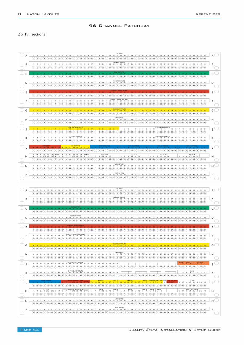
Page 54 Duality δelta Installation & Setup Guide
D – Patch Layouts Appendices
17 18 19 20 21 22 23 249 10 11 12 13 14 15 161 2 3 4 5 6 7 8 25 26 27 28 29 30 31 32 33 34 35 36 37 38 39 40 41 42 43 44 45 46 47 48
17 18 19 20 21 22 23 249 10 11 12 13 14 15 161 2 3 4 5 6 7 8 25 26 27 28 29 30 31 32 33 34 35 36 37 38 39 40 41 42 43 44 45 46 47 48
17 18 19 20 21 22 23 249 10 11 12 13 14 15 161 2 3 4 5 6 7 8 25 26 27 28 29 30 31 32 33 34 35 36 37 38 39 40 41 42 43 44 45 46 47 48
17 18 19 20 21 22 23 249 10 11 12 13 14 15 161 2 3 4 5 6 7 8 25 26 27 28 29 30 31 32 33 34 35 36 37 38 39 40 41 42 43 44 45 46 47 48
17 18 19 20 21 22 23 249 10 11 12 13 14 15 161 2 3 4 5 6 7 8 25 26 27 28 29 30 31 32 33 34 35 36 37 38 39 40 41 42 43 44 45 46 47 48
17 18 19 20 21 22 23 249 10 11 12 13 14 15 161 2 3 4 5 6 7 8 25 26 27 28 29 30 31 32 33 34 35 36 37 38 39 40 41 42 43 44 45 46 47 48
17 18 19 20 21 22 23 249 10 11 12 13 14 15 161 2 3 4 5 6 7 8 25 26 27 28 29 30 31 32 33 34 35 36 37 38 39 40 41 42 43 44 45 46 47 48
17 18 19 20 21 22 23 249 10 11 12 13 14 15 161 2 3 4 5 6 7 8 25 26 27 28 29 30 31 32 33 34 35 36 37 38 39 40 41 42 43 44 45 46 47 48
17 18 19 20 21 22 23 249 10 11 12 13 14 15 161 2 3 4 5 6 7 8 25 26 27 28 29 30 31 32 33 34 35 36 37 38 39 40 41 42 43 44 45 46 47 48
17 18 19 20 21 22 23 249 10 11 12 13 14 15 161 2 3 4 5 6 7 8 25 26 27 28 29 30 31 32 33 34 35 36 37 38 39 40 41 42 43 44 45 46 47 48
17 18 19 20 21 22 23 249 10 11 12 13 14 15 161 2 3 4 5 6 7 8 25 26 27 28 29 30 31 32 33 34 35 36 37 38 39 40 41 42 43 44 45 46 47 48
17 18 19 20 21 22 23 249 10 11 12 13 14 15 161 2 3 4 5 6 7 8 25 26 27 28 29 30 31 32 33 34 35 36 37 38 39 40 41 42 43 44 45 46 47 48
EXT A3 SOURCE1 2 3 4 5 6 7 8
EXT A2 SOURCE1 2 3 4 5 6 7 8
MIX INSERTAL AR BL BR CL CR L R
EXT A1 SOURCE1 2 3 4 5 6 7 8
EXT A4 SOURCE1 2 3 4 5 6 7 8
ALL R C LFE LS RS L R
EXT A1 INAR BL BR CL CR ST MIXL R C LFE LS RS
EXT A2 INL R C LFE LS RS
EXT A3 INL R C LFE LS RS
EXT A4 INL R C LFE LS RS
MIX OUTPUTSAL AR BL BR CL CR L R
ALL R C LFE LS RS L R
AR BL BR CL CR ST MIX
MIC LINES9 10 11 12 13 14 15 161 2 3 4 5 6 7 8 17 18 19 20 21 22 23 24 33 34 35 36 37 38 39 4025 26 27 28 29 30 31 32 41 42 43 44 45 46 47 48
CHANNEL INPUTS9 10 11 12 13 14 15 161 2 3 4 5 6 7 8 17 18 19 20 21 22 23 24 33 34 35 36 37 38 39 4025 26 27 28 29 30 31 32 41 42 43 44 45 46 47 48
DAW OUTPUTS9 10 11 12 13 14 15 161 2 3 4 5 6 7 8 17 18 19 20 21 22 23 24 33 34 35 36 37 38 39 4025 26 27 28 29 30 31 32 41 42 43 44 45 46 47 48
MONITOR INPUTS9 10 11 12 13 14 15 161 2 3 4 5 6 7 8 17 18 19 20 21 22 23 24 33 34 35 36 37 38 39 4025 26 27 28 29 30 31 32 41 42 43 44 45 46 47 48
CHANNEL INSERT SENDS9 10 11 12 13 14 15 161 2 3 4 5 6 7 8 17 18 19 20 21 22 23 24 33 34 35 36 37 38 39 4025 26 27 28 29 30 31 32 41 42 43 44 45 46 47 48
9 10 11 12 13 14 15 161 2 3 4 5 6 7 8 17 18 19 20 21 22 23 24CHANNEL INSERT RETURNS
33 34 35 36 37 38 39 4025 26 27 28 29 30 31 32 41 42 43 44 45 46 47 48
CHANNEL OUTPUTS9 10 11 12 13 14 15 161 2 3 4 5 6 7 8 17 18 19 20 21 22 23 24 33 34 35 36 37 38 39 4025 26 27 28 29 30 31 32 41 42 43 44 45 46 47 48
DAW INPUTS9 10 11 12 13 14 15 161 2 3 4 5 6 7 8 17 18 19 20 21 22 23 24 33 34 35 36 37 38 39 4025 26 27 28 29 30 31 32 41 42 43 44 45 46 47 48
TRACK BUS OUTPUTS CHANNEL KEY INPUTS9 10 11 12 13 14 15 161 2 3 4 5 6 7 8 17 18 19 20 21 22 23 24 9 10 11 12 13 14 15 161 2 3 4 5 6 7 8 17 18 19 20 21 22 23 24
RECORDER INPUTS9 10 11 12 13 14 15 161 2 3 4 5 6 7 8 17 18 19 20 21 22 23 24 33 34 35 36 37 38 39 4025 26 27 28 29 30 31 32 41 42 43 44 45 46 47 48
CHANNEL KEY INPUTS
D
E
F
A
B
C
G
H
J
K
L
M
D
E
F
A
B
C
G
H
J
K
L
M
MAIN LS BAL AR BL BR CL CR L R
MINI BMAIN LS AMONITOR INSERT SENDL R C LFE LS RS Lt Rt
DECODER AL AR BL BR CL CR L RMINI A
L R L RF/B A OUT F/B B OUT
INLSN
OUTLSN
OUTT/B OSC
AMP INL R C LFE LS RS
FX IN
MONITOR INSERT RTNL R C LFE LS RS Lt Rt
ENCODER L RAMP IN AMP IN
L R C LFE LS RS L RAMP IN
L RAMP A
L RAMP B
1 2 3 4L R L R
FX OUT1L 1R 2L 2R 3L 3R 4L 4R
ECHO RETURN IN1L 1R 2L 2R 3L 3R 4L 4R
MIC LINES
CHANNEL INPUTS
DAW OUTPUTS
MONITOR INPUTS
CHANNEL INSERT SENDS
CHANNEL INSERT RETURNS
CHANNEL OUTPUTS
DAW INPUTS
D
E
F
A
B
C
G
H
J
K
L
M
D
E
F
A
B
C
G
H
J
K
L
M
65 66 67 68 69 70 71 7257 58 59 60 61 62 63 6449 50 51 52 53 54 55 56
65 66 67 68 69 70 71 7257 58 59 60 61 62 63 6449 50 51 52 53 54 55 56
65 66 67 68 69 70 71 7257 58 59 60 61 62 63 6449 50 51 52 53 54 55 56
65 66 67 68 69 70 71 7257 58 59 60 61 62 63 6449 50 51 52 53 54 55 56
65 66 67 68 69 70 71 7257 58 59 60 61 62 63 6449 50 51 52 53 54 55 56
65 66 67 68 69 70 71 7257 58 59 60 61 62 63 6449 50 51 52 53 54 55 56
65 66 67 68 69 70 71 7257 58 59 60 61 62 63 6449 50 51 52 53 54 55 56
65 66 67 68 69 70 71 7257 58 59 60 61 62 63 6449 50 51 52 53 54 55 56
65 66 67 68 69 70 71 7257 58 59 60 61 62 63 6449 50 51 52 53 54 55 56
65 66 67 68 69 70 71 7257 58 59 60 61 62 63 6449 50 51 52 53 54 55 56
73 74 75 76 77 78 79 80 81 82 83 84 85 86 87 88 89 90 91 92 93 94 95 96
73 74 75 76 77 78 79 80 81 82 83 84 85 86 87 88 89 90 91 92 93 94 95 96
65 66 67 68 69 70 71 7257 58 59 60 61 62 63 6449 50 51 52 53 54 55 56
65 66 67 68 69 70 71 7257 58 59 60 61 62 63 6449 50 51 52 53 54 55 56
73 74 75 76 77 78 79 80 81 82 83 84 85 86 87 88 89 90 91 92 93 94 95 96
73 74 75 76 77 78 79 80 81 82 83 84 85 86 87 88 89 90 91 92 93 94 95 96
65 66 67 68 69 70 71 7257 58 59 60 61 62 63 6449 50 51 52 53 54 55 56
65 66 67 68 69 70 71 7257 58 59 60 61 62 63 6449 50 51 52 53 54 55 56
73 74 75 76 77 78 79 80 81 82 83 84 85 86 87 88 89 90 91 92 93 94 95 96
73 74 75 76 77 78 79 80 81 82 83 84 85 86 87 88 89 90 91 92 93 94 95 96
65 66 67 68 69 70 71 7257 58 59 60 61 62 63 6449 50 51 52 53 54 55 56
65 66 67 68 69 70 71 7257 58 59 60 61 62 63 6449 50 51 52 53 54 55 56
73 74 75 76 77 78 79 80 81 82 83 84 85 86 87 88 89 90 91 92 93 94 95 96
73 74 75 76 77 78 79 80 81 82 83 84 85 86 87 88 89 90 91 92 93 94 95 96
65 66 67 68 69 70 71 7257 58 59 60 61 62 63 6449 50 51 52 53 54 55 56
65 66 67 68 69 70 71 7257 58 59 60 61 62 63 6449 50 51 52 53 54 55 56
73 74 75 76 77 78 79 80 81 82 83 84 85 86 87 88 89 90 91 92 93 94 95 96
73 74 75 76 77 78 79 80 81 82 83 84 85 86 87 88 89 90 91 92 93 94 95 96
65 66 67 68 69 70 71 7257 58 59 60 61 62 63 6449 50 51 52 53 54 55 56
65 66 67 68 69 70 71 7257 58 59 60 61 62 63 6449 50 51 52 53 54 55 56
73 74 75 76 77 78 79 80 81 82 83 84 85 86 87 88 89 90 91 92 93 94 95 96
73 74 75 76 77 78 79 80 81 82 83 84 85 86 87 88 89 90 91 92 93 94 95 96
CHANNEL KEY INPUTS65 66 67 68 69 70 71 7257 58 59 60 61 62 63 6449 50 51 52 53 54 55 56 1 2 3 4L R
CUE AL RCUE B FX SENDS
EXT B SOURCE1 2 3 4 5 6 7 8
EXT B IN1L 1R 2L 2R 3L 3R 4L 4R
17 18 19 20 21 22 23 249 10 11 12 13 14 15 161 2 3 4 5 6 7 8 25 26 27 28 29 30 31 32 33 34 35 36 37 38 39 40 41 42 43 44 45 46 47 48
17 18 19 20 21 22 23 249 10 11 12 13 14 15 161 2 3 4 5 6 7 8 25 26 27 28 29 30 31 32 33 34 35 36 37 38 39 40 41 42 43 44 45 46 47 48
9 10 11 12 13 14 15 161 2 3 4 5 6 7 8 17 18 19 20 21 22 23 24 33 34 35 36 37 38 39 4025 26 27 28 29 30 31 32 41 42 43 44 45 46 47 48USER OPTION
9 10 11 12 13 14 15 161 2 3 4 5 6 7 8 17 18 19 20 21 22 23 24 33 34 35 36 37 38 39 4025 26 27 28 29 30 31 32 41 42 43 44 45 46 47 48USER OPTION
N
P
N
P
73 74 75 76 77 78 79 80 81 82 83 84 85 86 87 88 89 90 91 92 93 94 95 96
73 74 75 76 77 78 79 80 81 82 83 84 85 86 87 88 89 90 91 92 93 94 95 96
73 74 75 76 77 78 79 80 81 82 83 84 85 86 87 88 89 90 91 92 93 94 95 96
73 74 75 76 77 78 79 80 81 82 83 84 85 86 87 88 89 90 91 92 93 94 95 96
73 74 75 76 77 78 79 80 81 82 83 84 85 86 87 88 89 90 91 92 93 94 95 96
73 74 75 76 77 78 79 80 81 82 83 84 85 86 87 88 89 90 91 92 93 94 95 96
73 74 75 76 77 78 79 80 81 82 83 84 85 86 87 88 89 90 91 92 93 94 95 96
73 74 75 76 77 78 79 80 81 82 83 84 85 86 87 88 89 90 91 92 93 94 95 96
73 74 75 76 77 78 79 80 81 82 83 84 85 86 87 88 89 90 91 92 93 94 95 96CHANNEL KEY INPUTS
9 10 11 12 13 14 15 161 2 3 4 5 6 7 8 17 18 19 20 21 22 23 24 33 34 35 36 37 38 39 4025 26 27 28 29 30 31 32 41 42 43 44 45 46 47 48USER OPTION
9 10 11 12 13 14 15 161 2 3 4 5 6 7 8 17 18 19 20 21 22 23 24 33 34 35 36 37 38 39 4025 26 27 28 29 30 31 32 41 42 43 44 45 46 47 48USER OPTION
N
P
N
P
65 66 67 68 69 70 71 7257 58 59 60 61 62 63 6449 50 51 52 53 54 55 56
65 66 67 68 69 70 71 7257 58 59 60 61 62 63 6449 50 51 52 53 54 55 56
73 74 75 76 77 78 79 80 81 82 83 84 85 86 87 88 89 90 91 92 93 94 95 96
73 74 75 76 77 78 79 80 81 82 83 84 85 86 87 88 89 90 91 92 93 94 95 96
96 Channel Patchbay
2 x 19” sections
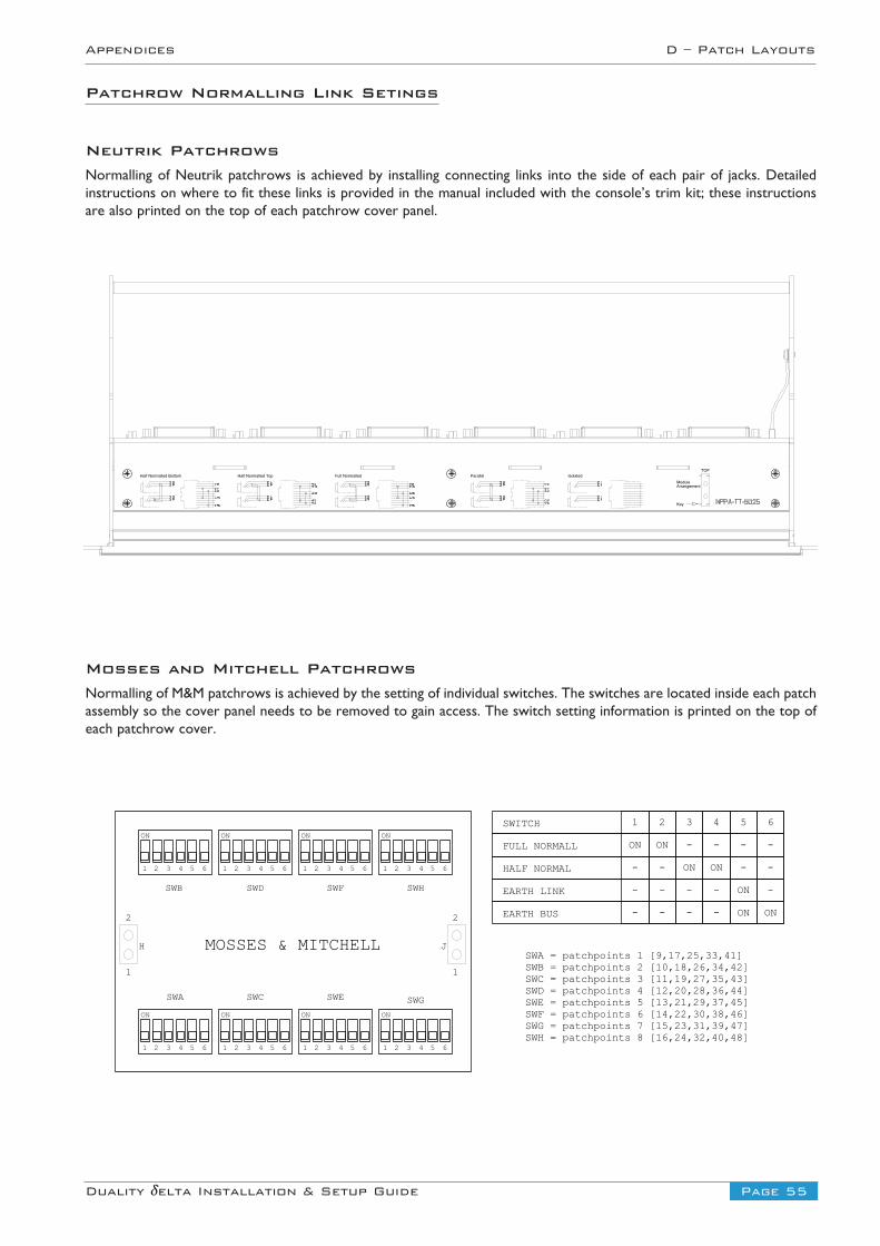
Page 55Duality δelta Installation & Setup Guide
Appendices D – Patch Layouts
Mosses and Mitchell PatchrowsNormalling of M&M patchrows is achieved by the setting of individual switches. The switches are located inside each patchassembly so the cover panel needs to be removed to gain access. The switch setting information is printed on the top ofeach patchrow cover.
SWA = patchpoints 1 [9,17,25,33,41] SWB = patchpoints 2 [10,18,26,34,42] SWC = patchpoints 3 [11,19,27,35,43] SWD = patchpoints 4 [12,20,28,36,44] SWE = patchpoints 5 [13,21,29,37,45] SWF = patchpoints 6 [14,22,30,38,46] SWG = patchpoints 7 [15,23,31,39,47] SWH = patchpoints 8 [16,24,32,40,48]
SWITCH 1
FULL NORMALL ON
HALF NORMAL -
EARTH LINK -
EARTH BUS -
2
ON
-
-
-
3
-
ON
-
-
4
-
ON
-
-
5
-
-
ON
ON
6
-
-
-
ON
SWB SWD SWF SWH
1
H
1
J
SWA SWC SWE SWG
MOSSES & MITCHELL
ON
1 2 3 4 5 6
ON
1 2 3 4 5 6
ON
1 2 3 4 5 6
ON
1 2 3 4 5 6
ON
1 2 3 4 5 6
ON
1 2 3 4 5 6
ON
1 2 3 4 5 6
ON
1 2 3 4 5 6
2 2
Half Normalled Bottom Half Normalled Top Full Normalled Parallel IsolatedModuleArrangement
Key
TOP
Patchrow Normalling Link Setings
Neutrik PatchrowsNormalling of Neutrik patchrows is achieved by installing connecting links into the side of each pair of jacks. Detailedinstructions on where to fit these links is provided in the manual included with the console’s trim kit; these instructionsare also printed on the top of each patchrow cover panel.
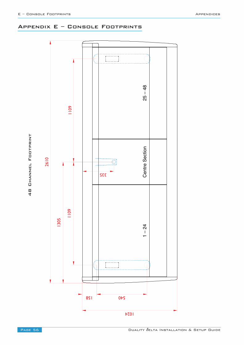
Page 56 Duality δelta Installation & Setup Guide
E – Console Footprints Appendices
Appendix E – Console Footprints
Cent
re S
ectio
n1
– 24
25 –
48
1305
1109
1109
2610
1024
158 540
335
48 Channel Footprint
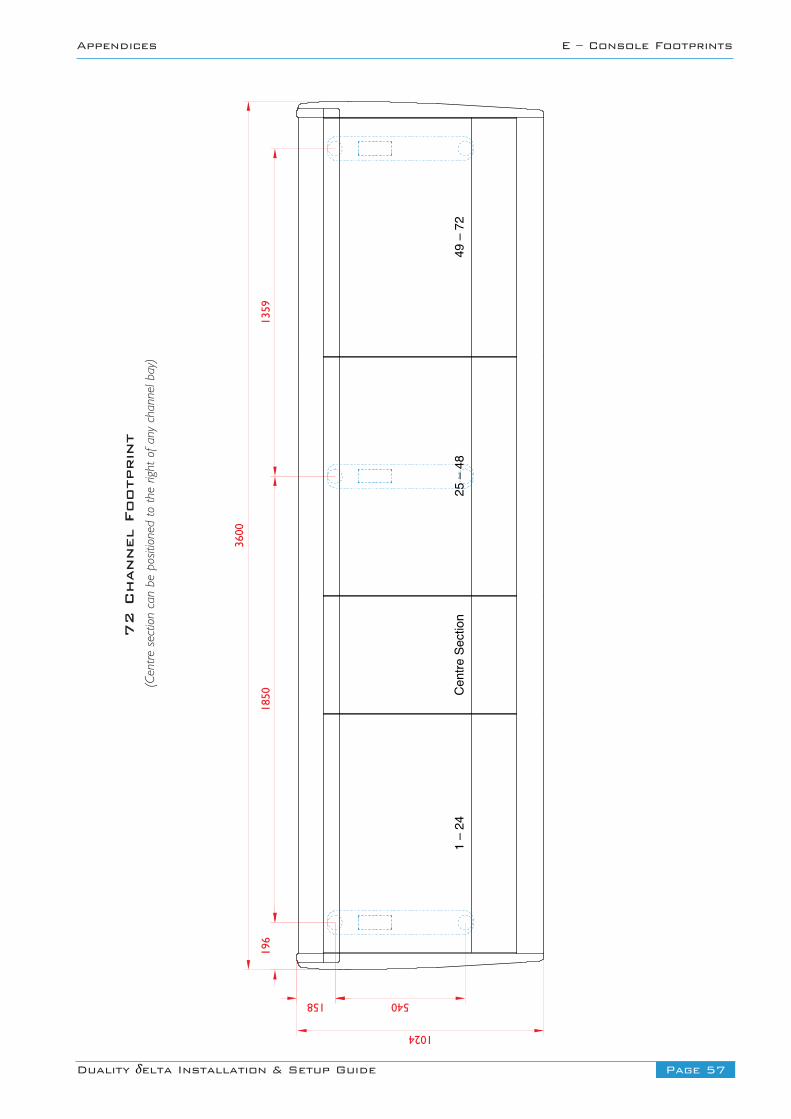
Page 57Duality δelta Installation & Setup Guide
Appendices E – Console Footprints
Cent
re S
ectio
n1
– 24
25 –
48
3600
1024
158 540
49 –
72
1359
1850
196
72 Channel Footprint
(Centre section can be positioned to the right of any channel bay)
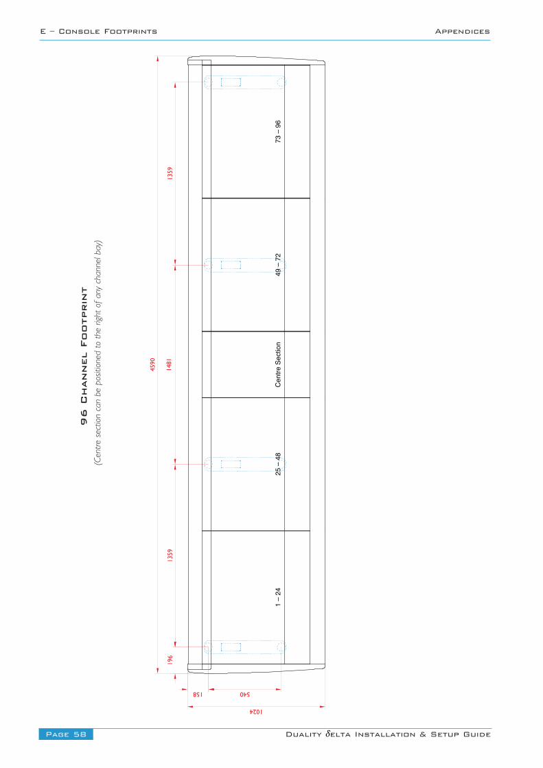
Page 58 Duality δelta Installation & Setup Guide
E – Console Footprints Appendices
Cent
re S
ectio
n1
– 24
25 –
48
1481
1359
4590
1024
158 540
49 –
72
73 –
96
1359
196
96 Channel Footprint
(Centre section can be positioned to the right of any channel bay)
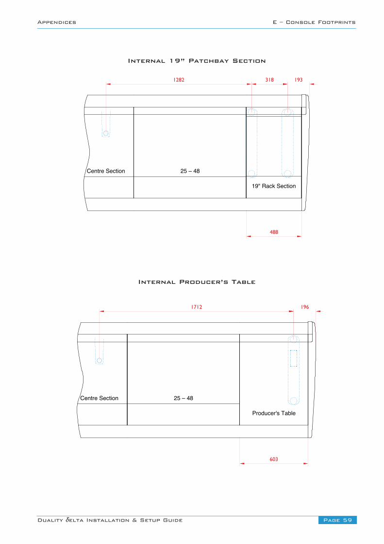
Page 59Duality δelta Installation & Setup Guide
Appendices E – Console Footprints
Internal 19” Patchbay Section
Internal Producer’s Table
Centre Section 25 – 48
1282 318
488
193
19" Rack Section
Centre Section 25 – 48
1712
603
196
Producer's Table
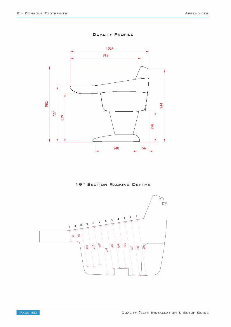
Page 60 Duality δelta Installation & Setup Guide
E – Console Footprints Appendices
62972
7
982
398
944
918
1024
156540
Duality Profile
19” Section Racking Depths
76 83
268
277
268 347
311
313
322 378
387
396
12 11 10 9 8 7 6 5 4 3 2 1
Page 61Duality δelta Installation & Setup Guide
Appendices F – Environmental Specifications
Appendix F – Environmental Specification
Notes Relating to Static and Air Conditioning
• Any item of electronic equipment can be affected by electrostatic discharge. It is considered good practice to avoidusing fully insulating floor coverings in technical areas.
• Air conditioning will usually be required. Note however, that a cool and dry atmosphere can significantly increasethe likelihood of a build-up of static charge. It is recommended that air conditioning systems are designed such thatthe relative humidity does not fall below 30% during periods of operation.
Temperature Operating: 5 to 30 Deg. CNon-operating: -20 to 50 Deg. CMax. Gradient: 15 Deg. C/Hour
Relative Humidity Operating: 30 to 80 %Non-operating: 5 to 90 %Max. Wet bulb: 29 Deg. C (non-condensing)
Vibration Operating: < 0.2 G (3 - 100Hz.)Non-operating, power off: < 0.4 G (3 - 100Hz.)
Shock Operating: < 2 G (10mSec. Max.)Non-operating: < 10 G (10mSec. Max.)
Altitude Operating: 0 to 3,000 m(Above sea level) Non-operating: 0 to 12,000 m